WO2024201711A1 - タッチスクリーン用入力システム - Google Patents
タッチスクリーン用入力システム Download PDFInfo
- Publication number
- WO2024201711A1 WO2024201711A1 PCT/JP2023/012515 JP2023012515W WO2024201711A1 WO 2024201711 A1 WO2024201711 A1 WO 2024201711A1 JP 2023012515 W JP2023012515 W JP 2023012515W WO 2024201711 A1 WO2024201711 A1 WO 2024201711A1
- Authority
- WO
- WIPO (PCT)
- Prior art keywords
- input
- touch screen
- display input
- display
- conductor
- Prior art date
- Legal status (The legal status is an assumption and is not a legal conclusion. Google has not performed a legal analysis and makes no representation as to the accuracy of the status listed.)
- Ceased
Links
Images

















Classifications
-
- G—PHYSICS
- G06—COMPUTING OR CALCULATING; COUNTING
- G06F—ELECTRIC DIGITAL DATA PROCESSING
- G06F3/00—Input arrangements for transferring data to be processed into a form capable of being handled by the computer; Output arrangements for transferring data from processing unit to output unit, e.g. interface arrangements
- G06F3/01—Input arrangements or combined input and output arrangements for interaction between user and computer
- G06F3/03—Arrangements for converting the position or the displacement of a member into a coded form
-
- G—PHYSICS
- G06—COMPUTING OR CALCULATING; COUNTING
- G06F—ELECTRIC DIGITAL DATA PROCESSING
- G06F3/00—Input arrangements for transferring data to be processed into a form capable of being handled by the computer; Output arrangements for transferring data from processing unit to output unit, e.g. interface arrangements
- G06F3/01—Input arrangements or combined input and output arrangements for interaction between user and computer
- G06F3/03—Arrangements for converting the position or the displacement of a member into a coded form
- G06F3/041—Digitisers, e.g. for touch screens or touch pads, characterised by the transducing means
Definitions
- the present invention relates to a technology that presents a physical phenomenon based on magnetic force to a user who inputs information onto a touch screen.
- Patent Documents 1 and 2 disclose technology that allows both input to a touch panel and the presentation of a force sensation.
- a first object which has south and north poles magnetized repeatedly on the same surface
- a second object which has south and north poles magnetized repeatedly on the same surface
- the user can perform input operations on the touch panel by manipulating this second object. At this time, the user perceives a force sensation based on the magnetic force between the first object and the second object.
- the force sense perceived by the user is based on the magnetic force between the first object and the second object. Therefore, the area in which the force sense can be presented to the user is limited to the area in which the first object is placed.
- the first object is placed on the input surface side of the touch panel. Therefore, when the technique of Patent Document 1 is applied to a touch screen, the user cannot see any of the content displayed in the area in which the first object is placed. This problem is common not only when a force sense is presented based on the magnetic force between the first object and the second object, but also when physical phenomena such as force sense, vibration, movement, and sound are presented based on the magnetic force between the first object and the second object.
- the present invention provides technology that can present a physical phenomenon based on magnetic force to a user who has input data onto a touch screen, while also allowing the user to visually recognize the content displayed in the area where this physical phenomenon can be presented.
- a touchscreen input system for inputting to a touchscreen has a first object and a second object.
- the first object includes a first surface, and the first surface is placed in contact with or in close proximity to a surface different from the display input surface of the touchscreen.
- the second object is placed in contact with or in close proximity to the display input surface, and includes at least one ferromagnetic part and a transparent material part.
- the position and/or attitude of the second object is changeable.
- a force in a first direction which is an attractive force or a repulsive force, is generated between a first region of the first surface of the first object that corresponds to a predetermined input position on the display input surface and the ferromagnetic part.
- a force in the first direction is not generated between a second region of the first surface of the first object that is close to the first region and the ferromagnetic part.
- a user of the touchscreen can view the display content of the display input surface through the transparent material part.
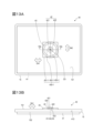
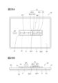
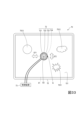
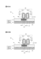
- Fig. 1A is a plan view illustrating the configuration of a touch screen input system according to a first embodiment
- Fig. 1B is a front view illustrating the configuration of the touch screen input system according to the first embodiment
- FIG. 2 is a plan view illustrating an object (first object) according to the first embodiment
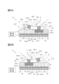
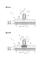
- Fig. 3A is a cross-sectional view taken along line 3A-3A in Fig. 1A
- Fig. 3B is a cross-sectional view showing a change in the portion of Fig. 3A
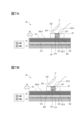
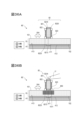
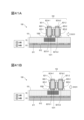
- Fig. 4A is a cross-sectional view taken along line 3A-3A in Fig. 1A
- Fig. 4B is a cross-sectional view showing a change in the portion of Fig. 4A.
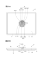
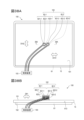
- FIG. 5A and 5B are plan and front views illustrating the configuration of a touch screen input system according to a second embodiment of the present invention
- Fig. 6A is a plan view illustrating an object (first object) according to the second embodiment
- Fig. 6B is a cross-sectional view taken along line 6B-6B of Fig. 5A
- 7A and 7B are cross-sectional views showing changes to the portion of FIG. 6B
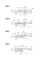
- 8A to 8D are plan views for illustrating the operation of the touch screen input system of the second embodiment.
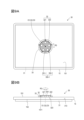
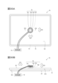
- 9A and 9B are plan and front views illustrating the configuration of a touch screen input system according to a third embodiment
- Fig. 10A is a plan view illustrating an object (first object) of the third embodiment
- FIG. 10B is a plan view illustrating an object (second object) of the third embodiment
- Fig. 10C is a bottom view illustrating the object (second object) of the third embodiment
- 11A to 11C are plan views for illustrating the operation of the touch screen input system of the third embodiment.
- 12A and 12B are plan and front views illustrating the configuration of a touch screen input system according to a modification of the third embodiment
- 13A and 13B are plan and front views illustrating the configuration of a touch screen input system according to a fourth embodiment
- Fig. 14A is a plan view illustrating an object (first object) of the fourth embodiment
- Fig. 14B is a plan view illustrating an object (second object) of the fourth embodiment
- FIG. 14C is a bottom view illustrating the object (second object) of the fourth embodiment.
- Fig. 15A is a cross-sectional view taken along line 15A-15A in Fig. 13A
- Fig. 15B is a cross-sectional view showing a change in the portion in Fig. 15A.
- Fig. 16A is a cross-sectional view showing a change in the portion of Fig. 15A.
- Fig. 16B is a cross-sectional view showing a change in the portion of Fig. 15A.
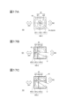
- 17A to 17C are plan views for illustrating the operation of the touch screen input system of the fourth embodiment.
- Fig. 18A is a plan view for illustrating the configuration of a touch screen input system according to a fifth embodiment
- Fig. 18A is a plan view for illustrating the configuration of a touch screen input system according to a fifth embodiment
- FIG. 18B is a front view for illustrating the configuration of the touch screen input system according to the fifth embodiment.
- Fig. 19A is a plan view illustrating an object (second object) according to the fifth embodiment, and Fig. 19B is a bottom view illustrating the object (second object) according to the fifth embodiment.
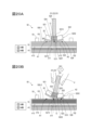
- Fig. 20A is a cross-sectional view taken along line 20A-20A in Fig. 18A, and Fig. 20B is a cross-sectional view showing a change in the portion in Fig. 20A.
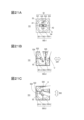
- 21A to 21C are plan views for illustrating the operation of the touch screen input system of the fifth embodiment.
- 22A and 22B are plan and front views illustrating the configuration of a touch screen input system according to a sixth embodiment
- 23A and 23B are plan views illustrating an object (first object) according to the sixth embodiment.
- Fig. 24A is a cross-sectional view taken along line 24A-24A in Fig. 22A
- Fig. 24B is a cross-sectional view showing a change in the portion in Fig. 24A.
- Figure 25A is a cross-sectional view showing a change in the portion of Figure 24A.
- Figure 25B is a cross-sectional view showing a change in the portion of Figure 24A.
- 26A to 26D are plan views illustrating the operation of the touch screen input system of the sixth embodiment.
- FIGS. 27A to 27D are plan views for illustrating the operation of the touch screen input system of the sixth embodiment.
- Fig. 28A is a plan view illustrating the configuration of a touch screen input system according to a first modified example of the sixth embodiment.
- Fig. 28B is a front view illustrating the configuration of the touch screen input system according to the first modified example of the sixth embodiment.
- 29A is a plan view illustrating the configuration of a touch screen input system according to a second modified example of the sixth embodiment.
- FIG. 29B is a front view illustrating the configuration of the touch screen input system according to the second modified example of the sixth embodiment.
- 30A and 30B are plan and front views illustrating the configuration of a touch screen input system according to the seventh embodiment; Fig.
- FIG. 31A is a cross-sectional view taken along line 31A-31A in Fig. 30A
- Fig. 31B is a cross-sectional view showing a change in the portion in Fig. 31A.
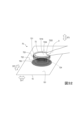
- FIG. 32 is a perspective view illustrating a method of using the touch screen input system of the seventh embodiment.
- FIG. 33 is a plan view for illustrating the configuration of a touch screen input system according to a modified example of the seventh embodiment.
- Fig. 34A is a plan view for illustrating the configuration of the touch screen input system according to the eighth and ninth embodiments.
- Fig. 34B is a front view for illustrating the configuration of the touch screen input system according to the eighth and ninth embodiments.
- 35A is a cross-sectional view taken along line 35A-35A in Fig. 34A
- Fig. 35B is a cross-sectional view showing a change in the portion in Fig. 35A
- Fig. 36A is a cross-sectional view showing a modification of the eighth embodiment
- Fig. 36B is a cross-sectional view showing a change in the portion of Fig. 36A
- Fig. 37A is a cross-sectional view taken along line 35A-35A in Fig. 34A, showing a modification of the ninth embodiment.
- Fig. 37B and Fig. 37C are cross-sectional views showing changes to the portion in Fig. 37A.
- FIG. 38A is a plan view for illustrating the configuration of a touch screen input system according to a tenth embodiment.
- Fig. 38B is a front view for illustrating the configuration of a touch screen input system according to a tenth embodiment.
- Fig. 39A is a cross-sectional view taken along line 39A-39A in Fig. 38A
- Fig. 39B is a cross-sectional view showing a change in the portion in Fig. 39A.
- Figure 40A is a cross-sectional view showing a change in the portion of Figure 39A.
- Figure 40B is a cross-sectional view showing a change in the portion of Figure 39A.
- Figure 41A is a cross-sectional view showing a change in the region of Figure 39A.
- Figure 41B is a cross-sectional view showing a change in the region of Figure 39A.
- FIG. 42 is a plan view for illustrating the configuration of a touch screen input system according to a modified example of the tenth
- an input system for a touch screen for inputting an input to a touch screen and presenting a force sense to a user is illustrated.
- the touch screen may be an electronic device or may be independent of the electronic device.
- the electronic device may be any device, for example, a smartphone terminal device, a tablet terminal device, a notebook type personal computer terminal device equipped with a touch screen, or other devices.
- the touchscreen input system of this embodiment has a first object and a second object.
- the first object includes a first surface, and the first surface is placed in contact with or in close proximity to a surface different from the display input surface of the touchscreen.
- the first object includes a ferromagnetic material such as iron, cobalt, nickel, gadolinium, etc.
- the first object may be magnetized or may not be magnetized.
- the second object is placed in contact with or in close proximity to the display input surface of the touchscreen, and includes at least one ferromagnetic material part and a transparent material part.
- the ferromagnetic material part includes a ferromagnetic material such as iron, cobalt, nickel, gadolinium, etc.
- the ferromagnetic material part may be a magnet or may not be a magnet.
- the touchscreen is interposed between the first object and the second object, and they are placed with a certain gap between them. This makes it possible to prevent the magnetism of the second object from being rewritten by the magnetic force of the first object, or the magnetism of the first object from being rewritten by the magnetic force of the second object.
- the position and/or posture of the second object is changeable. For example, the position and/or orientation of the second object relative to the first object and the touch screen can be changed.
- a force in a first direction which is an attractive force or a repulsive force, is generated between a first region of the first surface of the first object, which corresponds to a predetermined input position on the display input surface of the touch screen, and the ferromagnetic material part of the second object.
- This force is based on the magnetic force between the first surface of the first object and the ferromagnetic material part of the second object.
- a force in the first direction is not generated between a second region of the first surface of the first object, which is adjacent to the first region, and the ferromagnetic material part of the second object.
- a force in the first direction is generated or not generated between the first object and the second object depending on the positional relationship between the first object and the second object. This makes it possible to present a force sensation to the user of the touch screen.
- the user of the touchscreen can view the display content on the display input surface of the touchscreen through the transparent material portion of the second object.
- the first surface of the first object is placed in contact with or close to a surface different from the display input surface of the touchscreen.
- the first surface of the first object corresponds to an area capable of presenting a force sensation to the user.
- this first surface of the first object is not placed on the display input surface of the touchscreen. Therefore, the user can also view the content displayed in the area of the display input surface of the touchscreen capable of presenting a force sensation. Specific examples are shown below.
- FIG. 1A to 3B show an example of a touchscreen input system 10 that functions as a rocker switch (sometimes called a seesaw switch).
- the touchscreen input system 10 of this example is an input interface for inputting to a touchscreen 15 and presenting a force sense, and has an object 11 (first object), an object 12 (second object), and a frame portion 13.
- the object 11 in this example includes a plate surface 113 (first surface), and is configured so that the plate surface 113 is in contact with or in close proximity to a surface 152 different from the display input surface 151 of the touch screen 15.
- the surface 152 in this example is the surface opposite to the display input surface 151.
- the object 11 is, for example, a magnetic sheet including a ferromagnetic material.
- the object 11 does not necessarily have to be sheet-like, and may have other shapes such as a cube or a rectangular parallelepiped. As illustrated in FIG.
- two regions 111-1 and 111-2 (first regions) on the plate surface 113 of the object 11 are magnetized to the N pole, and a region 112 (second region) on the plate surface 113 different from the regions 111-1 and 111-2 is magnetized to the S pole.
- the regions 111-1 and 111-2 and the region 112 are close to each other.
- the regions 111-1 and 111-2 may be separated from the region 112.
- the edges of the regions 111-1 and 111-2 may be of other shapes, such as a rectangle or a triangle.
- the regions 111-1, 111-2, and 112 may be magnetized in advance by tracing the surface of the object 11 with a neodymium magnet or the like, or may be magnetized in advance by other methods (the same applies to the objects in the following embodiments and their modified examples).
- the object 12 in this example includes a seesaw structure (approximately an L-shaped plate structure) including a plate-shaped portion 120-1 (first portion) and a plate-shaped portion 120-2 (second portion) via a fulcrum 123.
- the plate-shaped portions 120-1 and 120-2 in this example are rectangular, and one end of each is connected to each other. However, this does not limit the present invention, and the plate-shaped portions 120-1 and 120-2 may have a shape other than a rectangular plate shape.
- one plate surface 123-1 of the plate-shaped portion 120-1 and one plate surface 123-2 of the plate-shaped portion 120-2 are disposed on the same side.
- the other plate surface 124-1 of the plate-shaped portion 120-1 and the other plate surface 124-2 of the plate-shaped portion 120-2 are both disposed on the opposite side of the plate surfaces 123-1 and 123-2.
- the end of the plate surface 123-1 is connected to the end of the plate surface 123-2
- the end of the plate surface 124-1 is connected to the end of the plate surface 124-2.
- the plate surfaces 123-1 and 123-2 are not arranged on the same plane, and they have a certain angle ⁇ 1 with each other.
- the plate surfaces 124-1 and 124-2 are not arranged on the same plane, and they have a certain angle ⁇ 2 with each other.
- the plate-shaped portion 120-1 and the plate-shaped portion 120-2 are connected to each other so as to be approximately V-shaped when viewed from the front (FIGS. 1B, 3A, and 3B).
- the bending angle of the approximately V-shape is an obtuse angle so that the plate surfaces 124-1 and 124-2 are easy to press. That is, as illustrated in FIG. 3A, 0° ⁇ 1, ⁇ 2 ⁇ 90°, for example, 3° ⁇ 1, ⁇ 2 ⁇ 90°.
- the boundary between the plate surfaces 123-1 and 123-2 is a line segment-like angle (a mountain-shaped corner), and this line segment-like boundary is the fulcrum 123.
- the plate-shaped portion 120-1 includes a ferromagnetic portion 121-1 (first ferromagnetic portion) and a transparent material portion 122-1
- the plate-shaped portion 120-2 includes a ferromagnetic portion 121-2 (second ferromagnetic portion) and a transparent material portion 122-2.
- the portion of the plate-shaped portion 120-1 other than the ferromagnetic portion 121-1 is the transparent material portion 122-1
- the portion of the plate-shaped portion 120-2 other than the ferromagnetic portion 121-2 is the transparent material portion 122-2.
- the plate-shaped portion 120-1 may include other members
- the plate-shaped portion 120-2 may include other members.
- the ferromagnetic material parts 121-1 and 121-2 include a ferromagnetic material.
- the ferromagnetic material parts 121-1 and 121-2 are magnets (permanent magnets, for example, neodymium magnets).
- Surface 1213-1 on the plate surface 123-1 side (touch screen 15 side) of the ferromagnetic material part 121-1 is magnetized to the south pole, and surface 1214-1 on the plate surface 124-1 side (opposite the touch screen 15) is magnetized to the north pole. It is desirable for surface 1213-1 to be arranged on the same plane or approximately on the same plane as plate surface 123-1, but they do not necessarily have to be arranged on the same plane or approximately on the same plane.
- the surface 1213-2 of the ferromagnetic part 121-2 on the plate surface 123-2 side (the touch screen 15 side) is magnetized to the S pole
- the surface 1214-1 on the plate surface 124-1 side is magnetized to the N pole.
- the surface 1213-2 and the plate surface 123-2 are arranged on the same plane or approximately on the same plane, but they do not necessarily have to be arranged on the same plane or approximately on the same plane.
- at least a part of the surface of the ferromagnetic part 121-1 and at least a part of the surface of the ferromagnetic part 121-2 in this embodiment are conductive.
- the ferromagnetic parts 121-1 and 121-2 themselves may be conductive, or a conductive material may be provided on at least a part of the surface of the ferromagnetic parts 121-1 and 121-2 (for example, metal plating, etc.).
- the conductor of the ferromagnetic part 121-1 is located at least on the surfaces of the faces 1213-1 and 1214-1, electrically connecting the faces 1213-1 and 1214-1.
- the conductor of the ferromagnetic part 121-2 is located at least on the surfaces of the faces 1213-2 and 1214-2, electrically connecting the faces 1213-2 and 1214-2.
- the ferromagnetic parts 121-1 and 121-2 are, for example, cylindrical in shape, but this does not limit the present invention, and they may be prismatic or have other shapes.
- the transparent material portions 122-1 and 122-2 include a transparent material or a material having transparency. This allows the user U to view the display content of the display input surface 151 through the transparent material portions 122-1 and 122-2 when the object 12 is placed in contact with or close to the display input surface 151 of the touch screen 15.
- the ferromagnetic parts 121-1 and 121-2 are fixed to the transparent material parts 122-1 and 122-2, respectively.
- an example is shown in which the ferromagnetic parts 121-1 and 121-2 are surrounded by the transparent material parts 122-1 and 122-2, respectively. That is, in this embodiment, an example is shown in which the transparent material parts 122-1 and 122-2 are arranged around the ferromagnetic parts 121-1 and 121-2, respectively.
- the transparent material parts 122-1 and 122-2 are connected to each other, and the boundary between them is the aforementioned fulcrum 123.
- the transparent material parts 122-1 and 122-2 may be integrally formed, or the transparent material parts 122-1 and 122-2 may be formed separately and connected to each other.
- the transparent material parts 122-1 and 122-2 may be separate from each other, and the ferromagnetic material parts 121-1 and 121-2 may be connected to each other.
- the ferromagnetic material parts 121-1 and 121-2 may be integrally formed, or the ferromagnetic material parts 121-1 and 121-2 may be formed separately and connected to each other.
- the transparent material parts 122-1 and 122-2 may be connected to each other, and the ferromagnetic material parts 121-1 and 121-2 may also be connected to each other.
- the frame 13 in this example is a rectangular frame-shaped member, and is configured to have a shape that allows the object 12 to be positioned inside the frame 13. That is, the size of the inside of the frame 13 is slightly larger than the outer shape of the object 12. However, the frame 13 is configured to have a shape that does not interfere with the operation (described later) of the object 12 placed inside the frame 13. It is desirable that the frame 13 includes a transparent material or a material having translucency. There is no limitation on the material of the frame 13, and it is desirable that the opposite side of the frame 13 can be seen through the frame 13. Examples of materials for the frame 13 include plastic, glass, etc.
- the object 11 is placed on the surface 152 side of the touch screen 15. At this time, the plate surface 113 of the object 11 is in contact with or close to the surface 152 of the touch screen 15.
- a frame portion 13 is placed on the display input surface 151 of the touch screen 15, and the object 12 is placed inside the frame portion 13.
- the frame portion 13 positions the object 12 at a predetermined location on the display input surface 151 side. However, these are placed so that the frame portion 13 does not interfere with the operation of the object 12 described later.
- the object 12 is placed, for example, in contact with the display input surface 151 of the touch screen 15.
- the fulcrum 123 of the object 12 is placed in contact with the display input surface 151.
- a member such as a thin sheet may be interposed between the object 12 and the display input surface 151.
- the object 12 may be placed close to the display input surface 151.
- the object 12 may be configured so that the fulcrum 123 of the object 12 is disposed close to the display input surface 151.
- the surface of the plate-like portion 120-1 (first portion) disposed on the display input surface 151 side is the plate surface 123-1 (first portion surface)
- the surface of the plate-like portion 120-2 (second portion) disposed on the display input surface 151 side is the plate surface 123-2 (second portion surface).
- the object 12 can rotate in the R1 rotation direction relative to the display input surface 151 and the object 11 around the fulcrum 123, which allows the attitude of the object 12 relative to the display input surface 151 and the object 11 to be changed.
- attitude A first attitude
- attitude B second attitude
- the surface 1213-1 of the ferromagnetic part 121-1 (first ferromagnetic part) of the plate-like part 120-1 (first part) is in contact with or close to the display input surface 151 ( Figure 3A).
- the surface 1213-1 of the ferromagnetic part 121-1 is located at a position corresponding to one area 111-1 (first area) of the plate surface 113 of the object 11.
- a predetermined input position 1511-1 of the display input surface 151 of the touch screen 15 is sandwiched between the surface 1213-1 of the ferromagnetic part 121-1 and the area 111-1 of the object 11.
- the surface 1213-1 is located directly above the area 111-1 and the input position 1511-1 when viewed from the front.
- the surface 1213-1 of the ferromagnetic part 121-1 is magnetized to the S pole
- the area 111-1 of the plate surface 113 of the object 11 is magnetized to the N pole. Therefore, in the posture A, an attractive force (force in the first direction) is generated between the ferromagnetic part 121-1 and the area 111-1 (first area) of the plate surface 113 (first surface) of the object 11 (first object) that corresponds to the input position 1511-1 of the display input surface 151.
- an attractive force force in the first direction
- the region 111-1 of the object 11 toward which the face 1213-1 of the ferromagnetic part 121-1 faces has a magnetic property that generates an attractive force between the region 111-1 and the face 1213-1.
- the region 122 located on the periphery of the region 111-1 of the object 11 toward which the face 1213-1 of the ferromagnetic part 121-1 faces has a magnetic property that does not generate an attractive force between the region 122 and the face 1213-1.
- the surface 1213-2 of the ferromagnetic part 121-2 (second ferromagnetic part) is in contact with or close to the display input surface 151 ( Figure 3B).
- the surface 1213-2 of the ferromagnetic part 121-2 is located at a position corresponding to the other area 111-2 (first area) of the plate surface 113 of the object 11.
- a predetermined input position 1511-2 of the display input surface 151 of the touch screen 15 is sandwiched between the surface 1213-2 of the ferromagnetic part 121-2 and the area 111-2 of the object 11.
- the surface 1213-1 is located directly above the area 111-2 and the input position 1511-2 when viewed from the front.
- the surface 1213-2 of the ferromagnetic part 121-2 is magnetized to the S pole, and the area 111-2 of the plate surface 113 of the object 11 is magnetized to the N pole. Therefore, in the posture B, an attractive force (force in the first direction) is generated between the ferromagnetic part 121-1 and the area 111-2 (first area) of the plate surface 113 (first surface) of the object 11 (first object) that corresponds to the input position 1511-2 of the display input surface 151.
- an attractive force force in the first direction
- the region 111-1 of the object 11 toward which the face 1213-2 of the ferromagnetic part 121-2 faces has a magnetic property that generates an attractive force between the region 111-1 and the face 1213-2.
- the region 122 located on the periphery of the region 111-2 of the object 11 toward which the face 1213-2 of the ferromagnetic part 121-2 faces has a magnetic property that does not generate an attractive force between the region 111-1 and the face 1213-2.
- a user U of the touch screen 15 presses down either the plate surface 124-1 or the plate surface 124-2 of the object 12 toward the object 11 with a body part such as a finger, thereby rotating the object 12 in the R1 rotation direction around the fulcrum 123, and can select either posture A (FIG. 3A) or posture B (FIG. 3B).
- posture A an attractive force is generated between the area 111-1 and the surface 1213-1. Therefore, when the user U presses down on the plate surface 124-2 in posture A, the user U perceives a reaction force based on the attractive force between the area 111-1 and the surface 1213-1.
- the posture changes to B.
- posture B In posture B, an attractive force is generated between the area 111-2 and the surface 1213-2. Therefore, when the user U presses down on the plate surface 124-1 in the posture B, the user U perceives a reaction force based on the attractive force between the area 111-2 and the surface 1213-2. When the pressing force on the plate surface 124-1 exceeds this reaction force, the posture becomes A.
- the magnetic force between the area 111-1 of the plate surface 113 (first surface) to which the surface 1213-1 of the ferromagnetic part 121-1 faces and the surface 1213-1 does not change the posture of the object 12 when the object 12 is in posture B, but when the object 12 is operated by the user U, the attractive force between the area 111-1 and the surface 1213-1 causes the object 12 to assume the posture A so that the object 12 is moved away from the posture B and closer to the posture A.
- the magnetic force between the area 111-2 of the plate surface 113 (first surface) to which the surface 1213-2 of the ferromagnetic part 121-2 faces and the surface 1213-2 does not change the posture of the object 12 when the object 12 is in posture A, but when the object 12 is operated by the user U, the attractive force between the area 111-2 and the surface 1213-2 causes the object 12 to assume posture B so that the object 12 is moved away from posture A and closer to posture B.
- the two switchable states may be, for example, an ON state and an OFF state, or two different ON states.
- the touch screen input system 10 of this embodiment is configured so that the conductor of the object 12 comes into contact with or approaches the input position 1511-1 by the operation of the user U.
- the touch screen input system 10 can not only present the force sense of the rocker switch as described above to the user U, but also input to the touch screen 15 according to the switching. That is, the above-mentioned pressing operation of the ferromagnetic part 121-1 is performed in a state in which the user U touches the conductor located on the surface 1214-1 of the ferromagnetic part 121-1.
- this conductor is also located on the surface 1213-1, and electrically connects the surface 1213-1 and the surface 1214-1.
- the surface 1213-1 comes into contact with or approaches the display input surface 151 (FIG. 3A).
- input is performed to the input position 1511-1 of the display input surface 151.
- the above-mentioned pressing operation of the ferromagnetic part 121-2 is performed in a state where the user U touches a conductor located on the surface 1214-2 of the ferromagnetic part 121-2.
- this conductor is also located on the surface 1213-2, electrically connecting the surfaces 1213-2 and 1214-2.
- the content displayed around the input positions 1511-1, 1511-2 on the display input surface 151 is different from the content displayed around the positions on the display input surface 151 where the conductor is not in contact with or close to the input positions.
- posture A FIG. 3A
- the surface 1213-1 of the ferromagnetic part 121-1 is in contact with or close to the input position 1511-1.
- the display content 150-1 is displayed around the input position 1511-1.
- display content 150-2 as shown in FIG. 3B is not displayed around input position 1511-2.
- surface 1213-2 of ferromagnetic part 121-2 is in contact with or close to input position 1511-2.
- display content 150-2 is displayed around input position 1511-2.
- User U can see transparent material part 122-1 of object 12, and can visually recognize display content 150-2 through this transparent material part 122-2.
- display content 150-1 as shown in FIG. 3A is not displayed around input position 1511-1. (FIG. 3B).
- the contents displayed around the input positions 1511-1 and 1511-2 on the display input surface 151 when the conductor comes into contact with or close to the input positions 1511-1 and 1511-2 by the operation of the user U may be different from the contents displayed around the input positions 1511-1 and 1511-2 on the display input surface 151 when this trigger does not occur.
- the above-mentioned display contents 150-1 may be displayed not only during the period when the conductor comes into contact with or close to the input position 1511-1, but also for a predetermined time (for example, only for a few seconds immediately after the contact or closeness) when the conductor comes into contact with or close to the input position 1511-1.
- the above-mentioned display contents 150-1 may be displayed for a predetermined time when the conductor comes into contact with or close to the input position 1511-1, regardless of whether the posture of the object 12 is A or B.
- the display content 150-2 may be displayed continuously for a predetermined period of time, not just during the period during which the conductor is in contact with or close to the input position 1511-2, but also when the conductor comes in contact with or close to the input position 1511-2.
- the display content 150-2 may be displayed continuously for a predetermined period of time when the conductor comes in contact with or close to the input position 1511-2, regardless of whether the posture of the object 12 thereafter is A or B.
- ⁇ Button-type touch screen input system 10> 1A, 1B, 2, 4A, and 4B show an example of a touch screen input system 10' that functions as a button.
- the only difference from the touch screen input system 10 that functions as a rocker switch described above is the magnetic pole of the ferromagnetic part 121-1 of the object 12. That is, as shown in FIGS. 4A and 4B, in the case of the touch screen input system 10', the surface 1213-1 of the ferromagnetic part 121-1 on the plate surface 123-1 side is magnetized to the N pole, and the surface 1214-1 on the plate surface 124-1 side is magnetized to the S pole.
- the surface 1213-1 of the ferromagnetic part 121-1 (first ferromagnetic part) of the plate-like part 120-1 (first part) is in contact with or in close proximity to the display input surface 151 ( Figure 4A).
- the surface 1213-1 of the ferromagnetic part 121-1 is magnetized to the north pole, and the area 111-1 of the plate surface 113 of the object 11 is also magnetized to the north pole.
- a repulsive force (force in the first direction) is generated between the area 111-1 (first area) of the plate surface 113 (first surface) of the object 11 (first object) that corresponds to the input position 1511-1 of the display input surface 151 and the ferromagnetic part 121-1.
- no repulsive force (force in the first direction) is generated between the ferromagnetic part 121-1 and the area 112 (second area corresponding to a predetermined second position different from the first position of the display input surface) of the plate surface 113 (first surface) of the object 11 (first object).
- the area 111-1 of the object 11 toward which the surface 1213-1 of the ferromagnetic part 121-1 faces has a magnetism that generates a repulsive force between the surface 1213-1.
- the area 122 located on the periphery of the area 111-1 of the object 11 toward which the surface 1213-1 of the ferromagnetic part 121-1 faces has a magnetism that does not generate a repulsive force between the surface 1213-1.
- the area 122 located on the periphery of the area 111-2 of the object 11 toward which the surface 1213-2 of the ferromagnetic part 121-2 faces has a magnetism that does not generate an attractive force between the surface 1213-2.
- the other configurations are the same as those of the touch screen input system 10.
- the user U perceives a reaction force due to the repulsive force between the surface 1213-1 (north pole) and the area 111-1 (north pole).
- the magnetic force between the surface 1213-1 and the area 111-1 of the plate surface 113 (first surface) to which the surface 1213-1 of the ferromagnetic part 121-1 of the object 12 faces changes the object 12 to posture B when the object 12 is in posture A, and maintains the object 12 in posture B when the object 12 is in posture B.
- the user U perceives a reaction force from the plate surface 124-1 when the user presses down on the plate surface 124-1.
- the south pole and north pole described in the first embodiment may be reversed. That is, all parts that were south poles in the first embodiment (for example, surface 1213-1 in FIG. 3A) may be north poles, and all parts that were north poles in the first embodiment (for example, region 111-1 in FIG. 3A) may be south poles.
- the configuration in the first embodiment in which an attractive force is generated by different magnetic poles may be replaced with a configuration in which an attractive force is generated by one of the magnetic poles of a magnet and a ferromagnetic material that is not a magnet (e.g., iron).
- a magnet e.g., iron
- one of surface 1213-1 and region 111-1 in Figures 3A and 3B may be a ferromagnetic material that is not a magnet
- one of surface 1213-2 and region 111-2 may be a ferromagnetic material that is not a magnet.
- one of surface 1213-2 and region 111-2 in Figure 4B may be a ferromagnetic material that is not a magnet.
- the surface 1213-1 and the surface 1214-1 do not necessarily have to be electrically conductive, and a conductor does not necessarily have to be arranged on the surface 1214-1. Even in such a case, if the conductor on the surface 1213-1 is in contact with or close to two different points on the input position 1511-1 of the display input surface 151, input to the input position 1511-1 can be performed using the technology described in the following references 1 and 2.
- the surface 1213-2 and the surface 1214-2 do not necessarily have to be electrically conductive, and a conductor does not necessarily have to be arranged on the surface 1214-2. Even in such a case, if the conductor on surface 1213-2 is in contact with or close to two different points at input position 1511-2 on display input surface 151, input can be made to input position 1511-2 using the techniques described in References 1, 2, etc.
- At least a part of the surface of the ferromagnetic part 121-1 and at least a part of the surface of the ferromagnetic part 121-2 are conductors. However, if a conductor is located on the plate surface 123-1 and the plate surface 124-1 of the plate-shaped part 120-1 and electrically connects them, the surface of the ferromagnetic part 121-1 does not have to be a conductor. Similarly, if a conductor is located on the plate surface 123-2 and the plate surface 124-2 of the plate-shaped part 120-2 and electrically connects them, the surface of the ferromagnetic part 121-2 does not have to be a conductor. Even in such a case, if the user U performs a push-down operation on the plate surface 124-1 or the plate surface 124-2 while touching the conductor, input can be made to the input position 1511-1 or the input position 1511-2 as described above.
- input to the touch screen 15 may be performed using the techniques described in References 1, 2, etc.
- the plate surfaces 123-1 and 124-1 do not necessarily have to be electrically conductive, and a conductor does not necessarily have to be arranged on the plate surface 124-1.
- the plate surfaces 123-2 and 124-2 do not necessarily have to be electrically conductive, and a conductor does not necessarily have to be arranged on the plate surface 124-2.
- a slider-type touchscreen input system that inputs data to a touchscreen by a slide operation.
- This slider-type touchscreen input system enables input of parameters by a slide operation and presentation of a force sense to a user.
- Such a slider-type touchscreen input system is an input interface used for an operation when a user sets a parameter value that can be freely set within a range between a predetermined minimum value and a maximum value to a desired value.
- a user can operate the volume of a sound output from a speaker, the brightness of a light, etc., by an operation (slide operation) of sliding a slider (moving the slider in a predetermined axial direction).
- the same reference numbers will be used for parts common to the matters described so far, and the description will be simplified.
- ⁇ Slider-type touch screen input system 20> 5A to 8D show examples of a slider-type touch screen input system 20.
- the touch screen input system 20 of this embodiment is an input interface for inputting to the touch screen 15 and presenting a force sense, and has an object 21 (first object), an object 22 (second object), and a frame portion 23.
- the object 21 of this embodiment includes a plate surface 213 (first surface), and is configured so that the plate surface 213 is in contact with or in close proximity to a surface 152 different from the display input surface 151 of the touch screen 15.
- the surface 152 in this example is the surface opposite to the display input surface 151.
- the object 21 is, for example, a magnetic sheet including a ferromagnetic material.
- the object 21 does not necessarily have to be sheet-like, and may have other shapes such as a cube or a rectangular parallelepiped. As illustrated in FIG.
- a repeating area is provided in advance on the plate surface 213 of the object 21, in which an area 211 (first area) and an area 212 (second area) are repeatedly arranged according to a specific line (first line) L1.
- first line first line
- an example is shown in which the area 211 is magnetized in advance to the N pole, and the area 212 is magnetized in advance to the S pole.
- the area 211 and the area 212 are different areas from each other.
- strip-shaped regions 211 and strip-shaped regions 212 are alternately and periodically arranged along a line L1 on the plate surface 213.
- the plate surface 213 is provided with a texture in which the regions 211 and 212 are alternately and repeatedly arranged along the line L1.
- the line L1 is a straight line, but the line L1 may also be a curved line.
- the object 22 in this example is a plate-like member having a plate surface 223 arranged on the touch screen 15 side and a plate surface 224 on the opposite side, and includes a ferromagnetic part 221 and a transparent material part 222.
- the object 22 functions as, for example, the slider described above.
- an example is shown in which the object 22 is in the shape of a rectangular plate, but the object 22 may be in another shape, such as a disk shape.
- the ferromagnetic body part 221 includes a ferromagnetic material.
- the ferromagnetic body part 221 in this embodiment is a magnet (permanent magnet, for example, a neodymium magnet).
- the surface 2213 on the plate surface 223 side (the touch screen 15 side) of the ferromagnetic body part 221 is magnetized to the north pole, and the surface 2214 on the plate surface 224 side (the opposite side to the touch screen 15) is magnetized to the south pole. It is desirable that the surface 2213 is arranged on the same plane or approximately on the same plane as the plate surface 223, but these do not necessarily have to be arranged on the same plane or approximately on the same plane.
- At least a portion of the surface of the ferromagnetic body part 221 in this embodiment is a conductor.
- the conductor of the ferromagnetic body part 221 is located at least on the surfaces of the surfaces 2213 and 2214, and electrically connects the surfaces 2213 and 2214.
- the ferromagnetic part 221 is, for example, cylindrical in shape, but this does not limit the present invention, and it may be prismatic or have some other shape.
- the transparent material section 222 includes a transparent material or a material having transparency. This allows the user U to view the display content of the display input surface 151 through the transparent material section 222 when the object 22 is placed in contact with or in close proximity to the display input surface 151 of the touch screen 15.
- the ferromagnetic part 221 is fixed to the transparent material part 222.
- the part of the object 22 other than the ferromagnetic part 221 is the transparent material part 222.
- the object 22 may include other members.
- an example is shown in which the ferromagnetic part 221 is surrounded by the transparent material part 222.
- an example is shown in which the transparent material part 222 is arranged around the ferromagnetic part 221.
- this does not limit the present invention.
- the frame 23 in this example is a rectangular frame-shaped member, and is configured to have a shape in which the object 22 is placed inside the frame 23 and the placed object 22 can be slid in a predetermined direction D2 (along the axis in the D2 direction). That is, the inner width of the frame 23 is slightly larger than the outer shape of the object 22, and the inner length of the frame 23 is sufficiently larger than the object 22, so that the object 22 can be slid in this length direction D2.
- the frame 23 desirably includes a transparent material or a material having transparency.
- the minimum to maximum values of the parameters input to the touch screen 15 are assigned in ascending or descending order on a certain reference line LR on the display input surface 151 of the touch screen 15 of this embodiment.
- the touch screen input system 20 of this embodiment is an input interface used for an operation when setting a parameter value that can be freely set within a range between a predetermined minimum value and a maximum value to a desired value
- the positions corresponding to the minimum to maximum values of the parameter may be assigned along the reference line LR.
- the reference line LR is a line extending in the horizontal direction of the touch screen 15, for example, the left end of the area accepting the slide input operation may be assigned to the minimum value, and the right end of the area accepting the slide input operation may be assigned to the maximum value.
- the reference line LR is a line extending in the vertical direction of the touch screen 15, for example, the lower end of the area accepting the slide input operation may be assigned to the minimum value, and the upper end of the area accepting the slide input operation may be assigned to the maximum value.
- Display contents 250-1 and 250-2 representing such allocations can be displayed on the display input surface 151.
- the reference line LR is a straight line (line segment) extending in the horizontal direction of the touch screen 15, but this does not limit the present invention.
- the reference line LR may be a straight line (line segment) extending in the vertical direction of the touch screen 15, the reference line LR may be a straight line (line segment) extending in another direction, or the reference line LR may be a curved line.
- Display content 250-1 is displayed when user U is not performing an operation (when user U is not touching the conductor of ferromagnetic material section 221), and display content 250-2 is displayed when user U is performing an operation (when user U is touching the conductor of ferromagnetic material section 221).
- the visual element ⁇ of display content 250-1 is set to ⁇ 1
- the visual element ⁇ of display content 250-2 is set to ⁇ 2.
- visual element ⁇ includes size, shape, color, brightness, pattern, etc. Below, an example is shown in which visual element ⁇ is a pattern.
- the display content 250-1 of this embodiment includes a scale 251-1 corresponding to the parameter value and an axis 253-1 along the reference line LR.
- the visual element ⁇ of the scale 251-1 corresponding to the input parameter value is ⁇ 1
- the visual element ⁇ of the other scales 251-1 is ⁇ 2. It is desirable that the visual element ⁇ is different from the visual element ⁇ .
- the visual element ⁇ includes size, shape, color, brightness, and pattern.
- the visual element ⁇ is size.
- this does not limit the present invention.
- the display content 250-2 of this embodiment includes a scale 251-2 corresponding to the parameter value and an axis 253-2 along the reference line LR.
- the scale 251-2 corresponding to the input parameter value and the other scales 251-1 can be visually distinguished by the difference in visual element ⁇ .
- the visual element ⁇ of the scale 251-1 corresponding to the input parameter value is ⁇ 1
- the visual element ⁇ of the other scales 251-1 is ⁇ 2.
- the object 21 is placed on the surface 152 side of the touch screen 15.
- the plate surface 213 of the object 21 is in contact with or close to the surface 152 of the touch screen 15.
- a frame portion 23 is placed on the display input surface 151 of the touch screen 15, and the object 22 is placed inside the frame portion 23.
- This frame portion 23 positions the object 22 so that it can slide in the D2 direction along the reference line LR on the display input surface 151 side. That is, the object 21 and the object 22 are placed so that the reference line LR on the display input surface 151 is placed along the line L1 of the object 21, and the ferromagnetic part 221 of the object 22 is placed on or near the reference line LR.
- the object 22 is placed, for example, in contact with the display input surface 151 of the touch screen 15.
- the plate surface 223 of the object 22 is placed in contact with the display input surface 151.
- a member such as a thin sheet may be interposed between the object 22 and the display input surface 151.
- the plate surface 223 of the object 22 may be disposed close to the display input surface 151.
- the object 22 thus arranged on the display input surface 151 can be slid in the direction D2 along the reference line LR. This sliding can change the relative position of the object 22 with respect to the object 21 and the display input surface 151.
- the plate surface 213 of the object 21 is magnetized in advance with N-pole regions 211 and S-pole regions 212 repeatedly magnetized along the line L1.
- the surface 2213 of the ferromagnetic part 221 of the object 22 is magnetized to the N-pole.
- a state A e.g., FIG.
- an attractive force is generated between an area 212 (south pole) of the plate surface 213 of the object 21 that corresponds to the input position 1511 of the display input surface 151, and the ferromagnetic part 221 (surface 2213 (north pole)).
- no attractive force is generated between an area 211 (north pole) of the plate surface 213 of the object 21 that is close to the area 212 (south pole) and the ferromagnetic part 221 (surface 2213 (north pole)).
- a repulsive force (force in the first direction) is generated between an area 211 (north pole) of the plate surface 213 of the object 21 that corresponds to the input position 1511 of the display input surface 151, and the ferromagnetic part 221 (surface 2213 (north pole)).
- no repulsive force (force in the first direction) is generated between an area 212 (south pole) of the plate surface 213 of the object 21 that is adjacent to the area 211 (north pole) and the ferromagnetic part 221 (surface 2213 (north pole)), but an attractive force is generated.
- the user U can touch the plate surface 224 of the object 22 with a body part such as a finger and slide the object 22 in the direction D2 along the reference line LR (FIGS. 7A to 8D).
- a body part such as a finger
- the above-mentioned states A and B are repeated depending on the relative position of the object 22 with respect to the object 21. Therefore, this sliding operation causes the state A in which the user U does not receive a repulsive force from the object 22 and the state B in which the user U receives a repulsive force to be repeated.
- the user U perceives a force sensation (a sense of unevenness) associated with the sliding operation.
- the touch screen input system 20 of this embodiment is configured so that the conductor of the object 22 comes into contact with or approaches the input position 1511 of the display input surface 151 of the touch screen 15 when the user U performs a slide operation.
- the touch screen input system 20 not only presents the user U with the force sensation associated with the slide operation as described above, but can also perform an input operation to the touch screen 15 in response to the slide operation (the operation of sliding the slider to set the parameter to a desired value, i.e., a slide input operation). That is, the above-mentioned slide operation of the object 22 is performed in a state where the user U touches the conductor located on the surface 2214 of the ferromagnetic material part 221.
- this conductor is also located on the surface 2213, and electrically connects the surface 2213 and the surface 2214. Therefore, when the user U performs a slide operation while touching this conductor, an input is performed at the input position 1511 of the display input surface 151 facing the surface 2213 of the ferromagnetic material part 221 (FIG. 7B). This input can be in state A, state B, or any state in between.
- the content displayed on the display input surface 151 of the touch screen 15 changes in response to a slide operation by the user U.
- the display content 250-1 (FIGS. 6B and 8A) displayed when the user U is not touching the object 22 (the above-mentioned conductor) and no slide operation is being performed
- the display content 250-2 (FIGS. 7A, 7B, 8B to 8D) displayed when the user U is touching the object 22 (the above-mentioned conductor) can be visually distinguished by the visual element ⁇ (e.g., a pattern).
- the display content 250-2 displayed on the display input surface 151 changes accordingly. That is, the scales 251-1 and 251-2 corresponding to the parameter values input by the slide operation and the scales 251-1 and 251-2 corresponding to the other parameter values can be visually distinguished by the visual element ⁇ (e.g., size) described above.
- the visual element ⁇ e.g., size
- display content 250-1 displayed on display input surface 151 may be, for example, the initial display content having visual element ⁇ 1, or it may be the visual element (for example, pattern) ⁇ 2 of display content 250-2 from the previous slide operation changed to visual element ⁇ 1.
- scale 251-1 corresponds to the current parameter value, and its visual element is ⁇ 1 (for example, large).
- rise 251-2 corresponds to the other parameter value, and its visual element is ⁇ 2 (for example, small).
- display content 250-2 is displayed on display input surface 151, in which visual element ⁇ 1 (e.g., a diagonal line pattern) of display content 250-1 in FIG. 8A is changed to visual element ⁇ 2 (e.g., a checkered pattern).
- visual element ⁇ 1 e.g., a diagonal line pattern
- visual element ⁇ 2 e.g., a checkered pattern
- the visual element ⁇ of the scale mark 251-2 near this input position 1511 is set to ⁇ 1 (e.g., large), and the visual element ⁇ of the other scale marks 251-2 is set to ⁇ 2 (e.g., small).
- the visual element ⁇ of the scale 251-2 on which the object 22 is placed becomes ⁇ 1 (e.g., large), and the visual element ⁇ of the other scales 251-2 becomes ⁇ 2 (e.g., small).
- the visual element ⁇ of the scale 251-2 is maintained and does not change. If the object 22 is slid further and the state of FIG. 8D is reached, this time the visual element ⁇ of another scale 251-2 on which the object 22 is placed becomes ⁇ 1 (e.g., large), and the visual element ⁇ of the other scales 251-2 becomes ⁇ 2 (e.g., small).
- At least a part of the object 22 is a conductor.
- the content (visual element ⁇ 1) displayed around the input position 1511 on the display input surface 151 is different from the content (visual element ⁇ 2) displayed around a position on the display input surface 151 where the conductor is not in contact with or close to the input position 1511 due to the operation of the user U.
- the content (visual element ⁇ 1) displayed around the input position 1511 on the display input surface when the conductor of the object 22 is in contact with or close to the input position 1511 due to the operation of the user U is different from the content (visual element ⁇ 2) displayed around a position on the display input surface 151 where this trigger does not occur.
- User U visually recognizes such display contents 250-1, 250-2 through the transparent material portion 222. In other words, user U can see the display contents 250-1, 250-2 that pass through the transparent material portion 222.
- a dial-type touchscreen input system that performs input to a touchscreen by a rotation operation.
- This dial-type touchscreen input system enables input of parameters by a rotation operation and presentation of a force sensation to a user.
- Such a dial-type touchscreen input system is an input interface used for an operation when a user sets a parameter value that can be freely set to a desired value, for example. For example, by rotating a dial (rotation operation), the user can simultaneously control the volume output from multiple speakers arranged around the user (operator) to control the direction from which sound comes to the user, control the position of a light arranged on the ceiling to control the direction from which light comes to the user, or operate the direction in which a machine is pointed.
- ⁇ Dial-type touch screen input system 30> 9A to 11C show an example of a dial-type touch screen input system 30.
- the touch screen input system 30 of this embodiment is an input interface for inputting to the touch screen 15 and presenting a force sense, and has an object 31 (first object), an object 32 (second object), and a frame portion 33.
- the object 31 of this embodiment includes a plate surface 313 (first surface), and is configured so that the plate surface 313 is in contact with or in close proximity to a surface 152 different from the display input surface 151 of the touch screen 15.
- the surface 152 in this example is the surface opposite to the display input surface 151.
- the object 31 is, for example, a magnetic sheet including a ferromagnetic material.
- the object 31 does not necessarily have to be sheet-shaped, and may have other shapes such as a cube or a rectangular parallelepiped. As illustrated in FIG.
- the plate surface 313 of the object 31 has a repeating area in which the area 311 (first area) and the area 312 (second area) are repeatedly arranged in a rotationally symmetric or approximately rotationally symmetric manner along the axis around the axis O1 (first axis) perpendicular or approximately perpendicular to the plate surface 313.
- the area 311 is magnetized in advance to the N pole
- the area 312 is magnetized in advance to the S pole.
- substantially vertical refers to a vertical or nearly vertical state.
- a nearly vertical state refers to, for example, a state in which the angle difference from the vertical is 5° or less.
- substantially rotationally symmetric refers to a state that is nearly rotationally symmetric.
- a nearly rotationally symmetric state refers to, for example, a state in which the angle difference from a rotationally symmetric arrangement is 5° or less.
- the regions 311 and 312 are different from each other.
- the plate surface 313 has the regions 311 and 312 alternately and periodically arranged along the axial direction R3 of the axis O1.
- the plate surface 313 may be provided with a texture in which the regions 311 and 312 are alternately repeated along the axial direction R3 of the axis O1.
- the edge portion of the region 311 is circular, but this does not limit the present invention, and the edge portion of the region 311 may be of other shapes such as a rectangle or a triangle.
- all regions of the plate surface 313 except the region 311 are the region 312, but this does not limit the present invention.
- Region 311, region 312, and other regions different therefrom may be provided on plate surface 313.
- region 311 having a circular periphery and region 312 having a circular periphery may be alternately and repeatedly arranged along the direction around axis O1, and other regions other than regions 311 and 312 may be provided on plate surface 313.
- the object 32 in this example is a plate-like member having a plate surface 323 (second surface) arranged on the touch screen 15 side and a plate surface 324 on the opposite side, and includes a transparent material portion 322 and a plurality of ferromagnetic material portions 321.
- the ferromagnetic material portion 321 is fixed to the transparent material portion 322.
- the portion of the object 32 other than the ferromagnetic material portion 321 is the transparent material portion 322.
- the object 32 may include other members.
- the object 32 functions as, for example, the above-mentioned dial.
- the ferromagnetic part 321 includes a ferromagnetic material.
- the ferromagnetic part 321 in this embodiment is a plurality of magnets.
- the surface 3214 on the plate surface 324 side (opposite the touch screen 15) of the ferromagnetic part 321 is magnetized to the N pole (FIG. 10B), and the surface 3213 on the plate surface 323 side (touch screen 15 side) is magnetized to the S pole (FIG. 10C).
- the plurality of ferromagnetic parts 321 are arranged rotationally symmetric or approximately rotationally symmetric along the axial direction R3 of the axis O2 (second axis) perpendicular or approximately perpendicular to the plate surface 323.
- the object 32 has a disk-like shape centered on the axis O2, and is rotationally symmetric or approximately rotationally symmetric about the axis O2.
- the positions of the plurality of ferromagnetic parts 321 of the object 32 correspond to the positions of the area 311 of the object 31.
- the surfaces 3213 of the multiple ferromagnetic parts 321 of the object 32 face the multiple regions 311 of the object 31, respectively.
- each of the surfaces 3213 of the multiple ferromagnetic parts 321 faces each of the multiple regions 311 of the object 31 in a one-to-one manner. More preferably, it is desirable that the shape of the surfaces 3213 of the multiple ferromagnetic parts 321 coincide or are close to the shape of the multiple regions 311 of the object 31.
- the ferromagnetic parts 321 are, for example, cylindrical in shape, but this does not limit the present invention, and they may be prismatic or have other shapes.
- the surface 3213 is arranged on the same plane or approximately on the same plane as the plate surface 323, but they do not necessarily have to be arranged on the same plane or approximately on the same plane.
- at least a portion of the surface of the ferromagnetic part 321 of this embodiment is a conductor.
- the conductor of the ferromagnetic part 321 is located at least on the surfaces of the faces 3213 and 3214, and electrically connects the faces 3213 and 3214.
- at least a portion of the object 32 (second object) is a conductor.
- the transparent material section 322 includes a transparent material or a material having transparency. This allows the user U to view the display content of the display input surface 151 through the transparent material section 322 when the object 32 is placed in contact with or in close proximity to the display input surface 151 of the touch screen 15.
- the frame 33 in this example is a circular frame-shaped member, inside which the object 32 is placed, and is configured to have a shape that allows the placed object 32 to rotate around the axis O2. That is, the inner diameter of the frame 33 is slightly larger than the diameter of the object 32. As with the frame 13 in the first embodiment, it is desirable for the frame 33 to include a transparent material or a material having transparency.
- the values of parameters input to the touch screen 15 are assigned according to a predetermined rule to each direction around an axis O3 (third axis) on the display input surface 151 of the touch screen 15 of this embodiment.
- the axis O3 is an axis perpendicular or approximately perpendicular to the display input surface 151.
- the touch screen input system 30 of this embodiment is an example of an input interface used for operations when a user (operator) sets the direction in which sound, light, etc.
- the upper side of the area that accepts rotational input operations of the touch screen 15 can be assigned to the front of the user U (the clockwise angle is 0 degrees relative to the orientation of the user U), the lower side of the area that accepts rotational input operations of the touch screen 15 can be assigned to the rear of the user (the clockwise angle is 180 degrees relative to the orientation of the user), the right side of the area that accepts rotational input operations of the touch screen 15 can be assigned to the right of the user (the clockwise angle is 90 degrees relative to the orientation of the user), and the left side of the area that accepts rotational input operations of the touch screen 15 can be assigned to the left of the user (the clockwise angle is 270 degrees relative to the orientation of the user).
- the touch screen input system 30 of this embodiment is an example of an input interface used for an operation in which a user sets the direction in which a machine is pointed
- the upper side of the area receiving rotation input operations of the touch screen 15 may be assigned to the north direction
- Display contents 350-1 and 350-2 representing the assignments can be displayed on the display input surface 151 of the touch screen 15.
- Display content 350-1 is displayed when user U is not performing an operation (when user U is not touching the conductor of ferromagnetic material section 321), and display content 350-2 is displayed when user U is performing an operation (when user U is touching the conductor of ferromagnetic material section 321).
- the visual element ⁇ of display content 350-1 is ⁇ 1
- the visual element ⁇ of display content 350-2 is ⁇ 2.
- visual element ⁇ is a pattern.
- Display content 350-1 of this embodiment includes circular portion 351-1, which is an area surrounded by a circle centered on axis O3, and scale 352-1 corresponding to the parameter value.
- display content 350-2 of this embodiment includes circular portion 351-2, which is an area surrounded by a circle centered on axis O3, and scale 352-2 corresponding to the parameter value.
- scales 352-1 and 352-2 corresponding to the parameter value are arranged around circular portions 351-1 and 351-2.
- scales 352-1 and 352-2 correspond to multiple ferromagnetic material portions 321 of object 32, and for example, scales 352-1 and 352-2 correspond one-to-one to ferromagnetic material portions 321.
- ⁇ Layout configuration> As illustrated in FIG. 9A and FIG. 9B, the object 31 is placed on the surface 152 side of the touch screen 15. At this time, the plate surface 313 of the object 31 is in contact with or close to the surface 152 of the touch screen 15. A frame portion 33 is placed on the display input surface 151 of the touch screen 15, and the object 32 is placed inside the frame portion 33.
- the touch screen 15 and the objects 31 and 32 are placed so that the above-mentioned axis O1 (first axis), axis O2 (second axis), and axis O3 (third axis) coincide with or are close to each other.
- the central axis of the frame portion 33 is also placed so that it coincides with or is close to at least one of these axes O1, O2, and O3.
- the frame portion 33 positions the object 32 on the display input surface 151 side so that it can rotate in the axial direction R3 centered on the axis O2.
- the object 32 is placed, for example, in contact with the display input surface 151 of the touch screen 15.
- the plate surface 323 of the object 32 is disposed in contact with the display input surface 151.
- a member such as a thin sheet may be interposed between the object 32 and the display input surface 151.
- the plate surface 323 of the object 32 may be disposed close to the display input surface 151.
- the object 32 arranged on the display input surface 151 in this manner can rotate around the axis O2. This rotational motion can change the orientation of the object 32 relative to the object 31 and the display input surface 151.
- the N-pole regions 311 and the S-pole regions 312 are repeatedly arranged along the axial direction R3 of the axis O1 (FIG. 10A).
- the faces 3213 of the multiple ferromagnetic parts 321 of the object 32 arranged along the axial direction R3 of the axis O2 are magnetized to the S-pole.
- the rotation of the object 32 can result in a rotational orientation A in which the face 3213 (S-pole) of the ferromagnetic part 321 of the object 32 is arranged toward the region 311 (N-pole) of the object 31, and a rotational orientation B in which the face 3213 (S-pole) is arranged toward the region 312 (S-pole) of the object 31.
- a repulsive force (force in the first direction) is generated between region 312 (south pole) of plate surface 313 of object 31 that corresponds to input position 1511 on display input surface 151, and ferromagnetic part 321 (surface 3213 (south pole)).
- no repulsive force (force in the first direction) is generated between region 311 (north pole) of plate surface 313 of object 31 that is close to region 312 (south pole) and ferromagnetic part 321 (surface 3213 (south pole)), but an attractive force is generated.
- the user U can touch the plate surface 324 of the object 32 with a body part such as a finger and rotate the object 32 in a direction R3 around the axis O2 (FIGS. 11A to 11C).
- a body part such as a finger
- the above-mentioned rotation posture A and rotation posture B are repeated depending on the posture of the object 32 relative to the object 31. Therefore, this rotation operation causes the user U to repeatedly assume the rotation posture A in which the user U does not receive a repulsive force from the object 32 and the rotation posture B in which the user U receives a repulsive force.
- the user U perceives a force sensation (a sense of unevenness) associated with the rotation operation.
- regions 311 and regions 312 are repeatedly arranged on the plate surface 313 of object 31 in a rotationally symmetric or approximately rotationally symmetric manner along the direction R3 around the axis O1, and a plurality of ferromagnetic material parts 321 are arranged on object 32 in a rotationally symmetric or approximately rotationally symmetric manner along the direction R3 around the axis O2.
- Objects 31 and 32 are arranged so that axes O1 and O2 coincide or are close to each other, thereby enabling smooth rotational operation of object 32.
- the touch screen input system 30 of this embodiment is configured so that the conductor of the object 32 comes into contact with or approaches the input position 1511 of the display input surface 151 of the touch screen 15 when the user U performs a rotation operation.
- the touch screen input system 30 not only presents the user U with the force sensation associated with the rotation operation as described above, but can also perform an input operation to the touch screen 15 in response to the rotation operation (an operation of rotating a dial to set a parameter to a desired value, i.e., a dial input operation, a rotation input operation). That is, the above-mentioned rotation operation of the object 32 is performed in a state where the user U touches the conductor located on the surface 3214 of the ferromagnetic part 321.
- this conductor is also located on the surface 3213, and electrically connects the surface 3213 and the surface 3214. Therefore, when the user U performs a rotation operation while touching this conductor, an input is made to the input position 1511 of the display input surface 151 facing the surface 3213 of the ferromagnetic part 321 (FIG. 9B). This input is possible in rotational position A, rotational position B, or any state between the two.
- the content displayed on the display input surface 151 of the touch screen 15 changes in response to a rotation operation by the user U.
- the display content 350-1 (FIG. 11) displayed when the user U is not touching the object 32 (the above-mentioned conductor) and no rotation operation is being performed, and the display content 350-2 (FIGS. 11B and 11C) displayed when the user U is touching the object 32 (the above-mentioned conductor) can be visually distinguished by the visual element ⁇ (e.g., a pattern).
- the display content 350-2 displayed on the display input surface 151 may change accordingly.
- the display content 350-2 when the attitude of the object 32 relative to the object 31 or the display input surface 151 is a specific rotational attitude e.g., right rotation
- the display content 350-2 when the attitude is a different rotational attitude e.g., left rotation
- the visual element ⁇ of the display content 350-2 when the ferromagnetic part 321 of the object 32 is in a rotational attitude rotating to the right may be ⁇ 1
- the visual element ⁇ of the display content 350-2 when the ferromagnetic part 321 is in a rotational attitude rotating to the left may be ⁇ 2.
- the regions 311 and 312 are repeatedly arranged on the plate surface 313 of the object 31 in a rotationally symmetric or approximately rotationally symmetric manner along the direction R3 around the axis O1
- a plurality of ferromagnetic parts 321 are arranged on the object 32 in a rotationally symmetric or approximately rotationally symmetric manner along the direction R3 around the axis O2
- the objects 31 and 32 are arranged so that the axes O1 and O2 coincide or are close to each other, thereby enabling a smooth rotation operation of the object 32.
- the object 32 may include a conductor that is rotationally asymmetric with respect to the axis O2 (second axis), and the conductor may be brought into contact with or close to the input position 1511 by the operation of the user U.
- the touch screen input system 30' may be a touch screen input system in which the object 32 of the touch screen input system 30 is replaced with an object 32' having such a conductor.
- the touch screen input system 30' of this modified example has an object 31 (first object), an object 32' (second object), and a frame portion 33.
- the object 32' is a plate-shaped member having a plate surface 323 (second surface) arranged on the touch screen 15 side and a plate surface 324 on the opposite side, and includes a transparent material portion 322, a plurality of ferromagnetic material portions 321, and a conductor portion 325.
- the conductor portion 325 is disposed on the plate surface 324 of the object 32' (the surface opposite to the plate surface 323 disposed on the touch screen 15 side).
- conductors are located on at least the surfaces 3213 and 3214 of the ferromagnetic portion 321, electrically connecting the surfaces 3213 and 3214.
- the conductor portion 325 is electrically connected to the conductor on the surface 3214 of any one of the ferromagnetic portions 321.
- the conductor located on the surface of the object 32' is rotationally asymmetric with respect to the axis O2.
- this does not limit the present invention, and any configuration may be used as long as the object 32' includes a conductor that is rotationally asymmetric with respect to the axis O2.
- the conductor portion 325 may be electrically connected to the conductor on the surface 3214 of two or more ferromagnetic portions 321.
- the display content 350-2 displayed on the display input surface 151 may change accordingly.
- the visual element ⁇ of the display content 350-2 when the ferromagnetic part 321 of the object 32' is in a rotational orientation where it is located at the position of the scale 352-2 may be ⁇ 1
- the visual element ⁇ of the display content 350-2 when the object is in any other rotational orientation may be ⁇ 2.
- the content (visual element ⁇ 1) displayed around said input position 1511 on the display input surface 151 is different from the content (visual element ⁇ 2) displayed around a position on the display input surface 151 where the conductor is not in contact with or close to it. It can also be said that the content (visual element ⁇ 1) displayed around input position 1511 on the display input surface when the conductor of object 32' is in contact with or close to input position 1511 due to user U's operation is different from the content (visual element ⁇ 2) displayed around a position on the display input surface 151 where this trigger does not occur.
- the surface of the ferromagnetic part 321 does not necessarily have to be a conductor.
- the plate surfaces 223 and 224 do not necessarily have to be electrically conductive, and a conductor does not necessarily have to be located on the plate surface 224.
- a thumbstick-type touchscreen input system for inputting to a touchscreen is exemplified.
- This thumbstick-type touchscreen input system enables input of parameters by thumbstick operation and presentation of a force sense to a user.
- ⁇ Thumbstick-type touch screen input system 40> 13A to 17C show examples of a thumbstick-type touch screen input system 40.
- the touch screen input system 40 of this embodiment is an input interface for inputting to the touch screen 15 and presenting a force sense, and has an object 41 (first object), an object 42 (second object), and a frame portion 43.
- the object 41 of this embodiment includes a plate surface 413 (first surface), and is configured so that the plate surface 413 is in contact with or in close proximity to a surface 152 different from the display input surface 151 of the touch screen 15.
- the surface 152 in this example is the surface opposite to the display input surface 151.
- the object 41 is, for example, a magnetic sheet including a ferromagnetic material.
- the object 41 does not necessarily have to be sheet-like, and may have other shapes such as a cube or a rectangular parallelepiped. As illustrated in FIG.
- the plate surface 413 of the object 41 is provided in advance with one region 411 (first region) arranged on an axis O1 perpendicular or approximately perpendicular to the plate surface 413 and the other region 412 (second region).
- first region arranged on an axis O1 perpendicular or approximately perpendicular to the plate surface 413 and the other region 412 (second region).
- second region an example is shown in which the region 411 is magnetized in advance to the N pole, and the region 412 is magnetized in advance to the S pole.
- the edge of region 411 is circular, but this does not limit the present invention, and the edge of region 411 may be of other shapes such as a rectangle or a triangle.
- all regions of plate surface 413 except region 411 are region 412, but this does not limit the present invention.
- Plate surface 413 may be provided with region 411, region 412, and other regions different from these.
- the object 42 in this example is a plate-shaped member having a plate surface 423 arranged on the touch screen 15 side and a plate surface 424 on the opposite side, and includes one ferromagnetic part 421 and a transparent material part 422 arranged on an axis O2 perpendicular or approximately perpendicular to the plate surface 423.
- the ferromagnetic part 421 is fixed to the transparent material part 422.
- the object 42 may include other members.
- the ferromagnetic part 421 includes a ferromagnetic material.
- the ferromagnetic part 421 in this embodiment is a magnet.
- the surface 4214 on the plate surface 424 side (opposite the touch screen 15) of the ferromagnetic part 421 is magnetized to the N pole (FIG. 14B), and the surface 4213 on the plate surface 423 side (touch screen 15 side) is magnetized to the S pole (FIG. 14C).
- the ferromagnetic part 421 is, for example, cylindrical in shape, but this does not limit the present invention, and these may be prismatic or of other shapes.
- the surface 4213 is arranged on the same plane or approximately on the same plane as the plate surface 423, but they do not necessarily have to be arranged on the same plane or approximately on the same plane.
- at least a portion of the surface of the ferromagnetic part 421 in this embodiment is a conductor.
- the conductor of the ferromagnetic part 421 is located at least on the surfaces of the faces 4213 and 4214, and electrically connects the faces 4213 and 4214.
- at least a part of the object 42 (second object) is a conductor.
- the transparent material section 422 includes a transparent material or a material having transparency. This allows the user U to view the display content of the display input surface 151 through the transparent material section 422 when the object 42 is placed in contact with or in close proximity to the display input surface 151 of the touch screen 15.
- the frame portion 43 in this example is a circular frame-shaped member, and is configured to have a shape in which an object 42 is arranged inside the frame portion 43 and the arranged object 42 can be moved (slid) in the D41 direction and the D42 direction along the display input surface 151 inside the frame portion 43. That is, the inner diameter of the frame portion 43 is sufficiently larger than the diameter of the object 42.
- the D41 direction is a specific direction parallel to the display input surface 151.
- the D42 direction is a direction perpendicular to the D41 direction and parallel to the display input surface 151.
- the frame portion 43 desirably includes a transparent material or a material having transparency.
- ⁇ Touch screen 15> As illustrated in FIG. 13A and FIG. 17A to FIG. 17C, display contents 450-1 and 450-2 representing the position of the object 42 can be displayed on the display input surface 151.
- a parameter P41 of the axis in the D41 direction and a parameter P42 of the axis in the D42 direction input to the touch screen 15 are assigned to an area centered on the axis O3 on the display input surface 151 of the touch screen 15 of this embodiment.
- the axis O3 is an axis perpendicular or substantially perpendicular to the display input surface 151.
- the reference values (minimum or maximum values) of the parameters P41 and P42 are assigned to the reference position O on the display input surface 151 that intersects with the axis O3.
- the reference value to the maximum value and/or minimum value of the parameter P41 are assigned in ascending or descending order from the reference position O on the display input surface 151 toward the outside in the D41 direction.
- the reference value to the maximum value and/or minimum value of the parameter P42 are assigned in ascending or descending order.
- Display content 450-1 is displayed when user U is not performing an operation (when user U is not touching the conductor of ferromagnetic material section 421), and display content 450-2 is displayed when user U is performing an operation (when user U is touching the conductor of ferromagnetic material section 421).
- the visual element ⁇ of display content 450-1 is ⁇ 1
- the visual element ⁇ of display content 450-2 is ⁇ 2.
- Display content 450-1 in this embodiment has a fixed outer frame 451-1 (e.g., a rectangular outer frame), a line 452-1 (e.g., a horizontal line) extending in the D41 direction that moves according to the position of object 42 in the D42 direction (coordinate of the axis in the D42 direction), and a line 453-1 (e.g., a vertical line) extending in the D42 direction that moves according to the position of object 42 in the D41 direction (coordinate of the axis in the D41 direction).
- the coordinate of the axis in the D42 direction of input position 1511 by object 42 on display input surface 151 and the coordinate of the axis in the D42 direction of line 452-1 are controlled to be the same or approximately the same.
- the coordinate of the axis in the D41 direction of input position 1511 by object 42 on display input surface 151 and the coordinate of the axis in the D41 direction of line 453-1 are controlled to be the same or approximately the same.
- display content 450-2 in this embodiment has a fixed outer frame 451-2 (e.g., a rectangular outer frame), a line 452-2 (e.g., a horizontal line) extending in the D41 direction that moves according to the position of object 42 in the D42 direction, and a line 453-2 (e.g., a vertical line) extending in the D42 direction that moves according to the position of object 42 in the D41 direction.
- the coordinate of the axis in the D42 direction of input position 1511 by object 42 on display input surface 151 and the coordinate of the axis in the D42 direction of line 452-2 are controlled to be the same or approximately the same.
- the coordinate of the axis in the D41 direction of input position 1511 by object 42 on display input surface 151 and the coordinate of the axis in the D41 direction of line 453-2 are controlled to be the same or approximately the same.
- an object 41 is disposed on the surface 152 side of the touch screen 15.
- the object 41 and the touch screen 15 are disposed so that the axis O1 of the object 41 and the axis O3 of the touch screen 15 coincide with or are close to each other, and the plate surface 413 of the object 41 is in contact with or close to the surface 152 of the touch screen 15.
- a frame portion 43 is disposed on the display input surface 151 of the touch screen 15, and an object 42 is disposed inside the frame portion 43.
- the frame portion 43 positions the object 42 so that it can slide in the D41 direction and the D42 direction on the display input surface 151 side.
- the frame portion 43 is disposed so that the axis O1 of the object 41 is located inside the frame portion 43.
- the frame portion 43 is disposed so that the axis O1 is located at the center or near the center inside the frame portion 43.
- the object 42 is disposed, for example, in contact with the display input surface 151 of the touch screen 15.
- the plate surface 423 of the object 42 is disposed in contact with the display input surface 151.
- this does not limit the present invention, and a member such as a thin sheet may be interposed between the object 42 and the display input surface 151.
- the plate surface 423 of the object 42 may be disposed close to the display input surface 151.
- Object 42 thus arranged on display input surface 151 can be slid in directions D41 and D42. This sliding can change the relative position of object 42 with respect to object 41 and display input surface 151.
- one N-pole region 411 and the other S-pole region 412 are pre-magnetized on plate surface 413 of object 41.
- surface 4213 of ferromagnetic part 421 of object 42 is magnetized to the S-pole.
- sliding of object 42 can result in state A (e.g., Figures 15A and 15B) in which surface 4213 (S-pole) of ferromagnetic part 421 of object 42 is arranged toward region 211 (N-pole) of object 41, or state B (e.g., Figures 16A and 16B) in which surface 4213 (S-pole) of ferromagnetic part 421 of object 42 is arranged toward region 412 (S-pole) of object 41.
- state A e.g., Figures 15A and 15B
- state B e.g., Figures 16A and 16B
- state A e.g., FIG. 15B
- an attractive force is generated between an area 411 (north pole) of the plate surface 413 of the object 41 that corresponds to the input position 1511 of the display input surface 151, and the ferromagnetic part 421 (surface 4213 (south pole)).
- no attractive force is generated between an area 412 (south pole) of the plate surface 413 of the object 41 that is close to the area 411 (north pole), and the ferromagnetic part 421 (surface 4213 (south pole)). Therefore, a force that tries to maintain the position of the area 411 of the object 41 is applied to the object 42 having the ferromagnetic part 421. That is, in state A, a force that tries to maintain state A is applied to the object 42.
- a repulsive force is generated between an area 412 (south pole) of the plate surface 413 of the object 41, which corresponds to the input position 1511 of the display input surface 151, and the ferromagnetic part 421 (surface 4213 (south pole)).
- no repulsive force is generated between an area 411 (north pole) of the plate surface 413 of the object 41, which is close to the area 412 (south pole), and the ferromagnetic part 421 (surface 4213 (south pole)).
- the object 42 having the ferromagnetic part 421 is subjected to a force that attracts it to the area 411 of the object 41 along the display input surface 151.
- a force that attracts it to the D411 side left side of Figure 16A.
- FIG. 16B when object 42 is placed on the D411 side (the left side of FIG. 16B) of region 411, object 42 receives a force that pulls it toward D412 (the right side of FIG. 16B). That is, in state B, a force that moves object 42 closer to state A is applied to object 42.
- the user U can touch the plate surface 424 of the object 42 with a body part such as a finger, and slide the object 42 in the D41 direction and the D42 direction on the display input surface 151 (FIGS. 15B, 16A, 16B, 17A, and 17B).
- the above-mentioned state A and state B are generated according to the relative position of the object 42 with respect to the region 411 of the object 41.
- a force that tries to maintain state A is applied to the object 42
- state B a force that tries to move the object 42 closer to state A is applied to the object 42.
- the user U perceives a force that tries to return the object 42 to the region 411 side (for example, the center or near the center) when performing a slide operation of the object 42.
- the touchscreen input system 40 of this embodiment is configured so that the conductor of the object 42 comes into contact with or approaches the input position 1511 of the display input surface 151 of the touchscreen 15 when the user U performs a slide operation.
- the touchscreen input system 40 not only presents the user U with the force sensation associated with the slide operation as described above, but can also perform an input operation to the touchscreen 15 in response to the slide operation (an operation of sliding a slider to set a parameter to a desired value, i.e., a slide input operation). That is, the slide operation of the object 42 described above is performed in a state in which the user U touches the conductor located on the surface 4214 of the ferromagnetic part 421.
- this conductor is also located on the surface 4213, and electrically connects the surfaces 4213 and 4214. Therefore, when the user U performs a slide operation while touching this conductor, input is performed at the input position 1511 of the display input surface 151, which faces the surface 4213 of the ferromagnetic part 421 (FIGS. 15B, 16A, 16B, 17A, and 17B). This input is possible in state A, state B, or any state between them.
- the content displayed on the display input surface 151 of the touch screen 15 changes according to the slide operation by the user U.
- the display content 450-1 (FIGS. 15A and 17A) displayed when the user U is not touching the object 42 (the above-mentioned conductor) and no slide operation is being performed
- the display content 450-2 (FIGS. 15B, 16A, 16B, 17B, 17C) displayed when the user U is touching the object 42 (the above-mentioned conductor) can be visually distinguished by the visual element ⁇ (e.g., a pattern).
- the display content 450-2 displayed on the display input surface 151 changes accordingly. That is, the position of the line 453-1 in the D41 direction changes according to the position of the object 42 in the D41 direction, and the position of the line 452-1 in the D41 direction changes according to the position of the object 42 in the D42 direction (FIGS. 17B and 17C).
- the coordinate of the axis in the D41 direction of the input position 1511 by the object 42 on the display input surface 151 and the coordinate of the axis in the D41 direction of the line 453-2 become the same or approximately the same
- the display content 450-2 changes so that the coordinate of the axis in the D42 direction of the input position 1511 by the object 42 on the display input surface 151 and the coordinate of the axis in the D42 direction of the line 452-2 become the same or approximately the same.
- At least a part of object 42 is a conductor.
- the content (lines 452-2 and 453-2) displayed around said input position 1511 on display input surface 151 is different from the content displayed around a position on display input surface 151 where this conductor is not in contact with or close to it. It can also be said that the content displayed around input position 1511 on the display input surface when the conductor of object 42 is in contact with or close to input position 1511 due to the operation of user U is different from the content displayed around a position on display input surface 1511 where this trigger does not occur.
- User U visually recognizes such display contents 450-1, 450-2 through the transparent material portion 422. In other words, user U can see display contents 450-1, 450-2 that pass through the transparent material portion 422.
- a joystick-type touch screen input system for inputting to a touch screen is illustrated.
- This joystick-type touch screen input system enables input of parameters by joystick operation and presentation of a force sense to a user.
- ⁇ Joystick-type touch screen input system 50> 18A to 21C show examples of a joystick-type touch screen input system 50.
- the touch screen input system 50 of this embodiment is an input interface for inputting to the touch screen 15 and presenting a force sense, and has an object 41 (first object), an object 52 (second object), and a frame portion 53.
- the object 41 is the same as that described in the fourth embodiment.
- the object 52 in this example has a rectangular plate-shaped central portion 5201, four rectangular plate-shaped inclined portions 5202 extending outward from the four sides of the central portion 5201, a rod-shaped conductor 525 extending from one plate surface 524 side of the central portion 5201, and a conductor 526 provided on the other plate surface 523 side of the central portion 5201 and the inclined portions 5202.
- the plate surface arranged on the touch screen 15 side is called the plate surface 523
- the plate surface on the opposite side is called the plate surface 524.
- Each of the inclined portions 5202 is connected to one of the sides of the central portion 5201 and inclined toward the plate surface 524 side.
- the inclined portions 5202 are warped toward the plate surface 524 side with respect to the central portion 5201.
- the plate surfaces 523 of the central portion 5201 and the inclined portion 5202 are connected, but the plate surfaces 523 of the central portion 5201 and the inclined portion 5202 are not arranged on the same plane, and have a certain angle ⁇ 5. Note that 0° ⁇ 5 ⁇ 180°, for example, 1° ⁇ 5 ⁇ 90°.
- the central portion 5201 includes one ferromagnetic portion 521 arranged on an axis O2 perpendicular or approximately perpendicular to the plate surface 523 of the central portion 5201, and the portion of the central portion 5201 other than the ferromagnetic portion 521 and the inclined portion 5202 are transparent material portions 522.
- the ferromagnetic portion 521 is fixed to the transparent material portion 522.
- the ferromagnetic part 521 includes a ferromagnetic material.
- the ferromagnetic part 521 is a magnet.
- the surface 5214 on the plate surface 524 side (opposite the touch screen 15) of the ferromagnetic part 521 is magnetized to the north pole
- the surface 5213 on the plate surface 423 side (touch screen 15 side) is magnetized to the south pole ( Figures 20A and 20B).
- the ferromagnetic part 521 is, for example, cylindrical in shape, but this does not limit the present invention, and the surface 5213 may be prismatic or of another shape. It is desirable that the surface 5213 is arranged on the same plane or approximately on the same plane as the plate surface 523, but they do not necessarily have to be arranged on the same plane or approximately on the same plane.
- the transparent material section 522 includes a transparent material or a material having transparency. This allows the user U to view the display content of the display input surface 151 through the transparent material section 522 when the object 52 is placed in contact with or in close proximity to the display input surface 151 of the touch screen 15.
- the conductor 525 extends parallel or approximately parallel to the axis O2.
- the conductor 525 and the conductor 526 are electrically conductive.
- the conductor 525 is connected to the ferromagnetic part 521
- the surface of the ferromagnetic part 521 is a conductor
- the conductors 525 and 526 are electrically conductive through the conductor of the ferromagnetic part 521.
- the conductors 525 and 526 may be electrically conductive through another conductor not shown. In other words, at least a part of the object 52 (second object) is a conductor.
- the conductor 526 may be provided on the entire plate surface 523, or on only a portion of the plate surface 523. However, the conductor 526 must be provided on the plate surface 523 of the central portion 5201 and on the plate surface 523 of each of the four inclined portions 5202.
- frame 53 in this example is a circular frame-like member, and is configured in a shape that allows object 52 to be placed inside.
- Frame 53 positions object 52 within a certain range, but is shaped so as not to interfere with the movement of object 52 based on the operation of user U.
- frame 53 desirably includes a transparent material or a material having transparency.
- ⁇ Touch screen 15> As illustrated in FIG. 18A and FIG. 21A to FIG. 21C, display contents 550-1 and 550-2 representing the tilt attitude of the object 52 can be displayed on the display input surface 151.
- a parameter P51 of the tilt in the D51 direction and a parameter P52 of the tilt in the D52 direction input to the touch screen 15 are assigned to an area centered on the axis O3 on the display input surface 151 of the touch screen 15 of this embodiment.
- the axis O3 is an axis perpendicular or substantially perpendicular to the display input surface 151.
- the D51 direction is a specific direction parallel to the display input surface 151.
- the D52 direction is a direction perpendicular to the D51 direction and parallel to the display input surface 151.
- the D51 direction is the left-right direction in FIG. 18A and the D52 direction is the up-down direction in FIG. 18A.
- the value of the parameter P51 representing the tilt attitude in one direction is assigned to the assigned area A1 on one side (e.g., the left side in FIG. 18A) in the D51 direction of the reference position O on the display input surface 151 intersecting with the axis O3, and the value of the parameter P51 representing the tilt attitude in this direction is assigned to the assigned area A2 on the other side (e.g., the right side in FIG.
- the value of the parameter P52 representing the tilt attitude in this direction is assigned to the assigned area A3 on one side (e.g., the upper side in FIG. 18A) in the D52 direction of the reference position O on the display input surface 151, and the value of the parameter P52 representing the tilt attitude in this direction is assigned to the assigned area A4 on the other side (e.g., the lower side in FIG. 18A) in the D52 direction of the reference position O on the display input surface 151.
- Display content 550-1 is displayed when user U is not performing an operation (when user U is not touching conductor 525), and display content 550-2 is displayed when user U is performing an operation (when user U is touching conductor 525).
- the visual element ⁇ of display content 550-1 is ⁇ 1
- the visual element ⁇ of display content 550-2 is ⁇ 2.
- Display content 550-1 in this embodiment has a fixed outer frame 551-1 (e.g., a rectangular outer frame), a line 552-1 (e.g., a horizontal line) extending in the D51 direction that moves in the D52 direction depending on the tilt orientation of object 52 in the D52 direction, and a line 553-1 (e.g., a vertical line) extending in the D52 direction that moves in the D51 direction depending on the tilt orientation of object 52 in the D51 direction.
- a fixed outer frame 551-1 e.g., a rectangular outer frame
- a line 552-1 e.g., a horizontal line
- a line 553-1 e.g., a vertical line
- display content 550-2 in this embodiment has a fixed outer frame 551-2 (e.g., a rectangular outer frame), a line 552-2 (e.g., a horizontal line) extending in the D51 direction that moves in the D52 direction depending on the tilt orientation of object 52 in the D52 direction, and a line 553-2 (e.g., a vertical line) extending in the D52 direction that moves in the D51 direction depending on the tilt orientation of object 52 in the D51 direction.
- a fixed outer frame 551-2 e.g., a rectangular outer frame
- a line 552-2 e.g., a horizontal line
- a line 553-2 e.g., a vertical line
- an object 41 is disposed on the surface 152 side of the touch screen 15.
- the object 41 and the touch screen 15 are disposed so that the axis O1 of the object 41 and the axis O3 of the touch screen 15 coincide with or are close to each other, and the plate surface 513 of the object 41 is in contact with or close to the surface 152 of the touch screen 15.
- a frame portion 53 is disposed on the display input surface 151 of the touch screen 15.
- the frame portion 53 is disposed so that the axis O1 of the object 41 is located inside the frame portion 53.
- the frame portion 53 is disposed so that the axis O1 is located at or near the center inside the frame portion 53.
- An object 52 is disposed inside the frame portion 53 on the display input surface 151.
- the frame portion 53 positions the object 52 on the display input surface 151 side so that the object 52 can be tilted in the D51 direction and the D52 direction.
- the object 52 arranged inside the frame portion 53 is arranged so that the plate surface 523 side is located on the display input surface 151 side.
- the object 52 is arranged so that the surface 5213 of the ferromagnetic part 521 faces the area 411 of the plate surface 413 of the object 41. That is, when the object 52 is not tilted, the objects 41 and 52, the frame portion 53, and the touch screen 15 are arranged so that the axis O2 coincides with or is close to the axes O1 and O3 (FIG.
- the object 52 is arranged, for example, in contact with the display input surface 151 of the touch screen 15.
- this does not limit the present invention, and a member such as a thin sheet may be interposed between the object 52 and the display input surface 151. That is, the object 52 may be arranged close to the display input surface 151 of the touch screen 15.
- the object 52 thus arranged on the display input surface 151 can be tilted in the D51 direction and the D52 direction with respect to the object 41 and the touch screen 15. That is, the axis O2 of the object 52 can be tilted in the D51 direction or the D52 direction with respect to the axis O1 of the object 41 and the axis O3 of the touch screen 15.
- one N-pole region 411 and the other S-pole region 412 are provided in advance on the plate surface 413 of the object 41.
- the surface 5213 of the ferromagnetic part 521 of the object 52 is magnetized to the S-pole. Therefore, in both the upright state A (FIG. 20A) and the tilted state B, an attractive force is generated between the region 411 (N-pole) of the plate surface 413 of the object 41 that corresponds to the input position 1511 of the display input surface 151 and the ferromagnetic part 521 (surface 5213 (S-pole)). This attractive force is maximum in the upright state A.
- the user U touches the conductor 525 of the object 52 with a body part such as a finger, and tilts the object 52 in the D51 direction and/or the D52 direction. That is, the axis O2 of the object 52 is tilted in the D51 direction and/or the D52 direction with respect to the axes O1 and O3 (FIGS. 20A to 21C).
- a force that tries to maintain the upright state A is applied to the object 52.
- a tilted state B where the object 52 is tilted
- a force that tries to return the object 52 to the upright state A is applied to the object 52.
- the user U perceives a force that tries to return the object 52 to the upright state A when tilting the object 52.
- the conductor 526 provided on the plate surface 523 of the central portion 5201 of the object 52 contacts or is close to the input position 1511 (reference position O) of the display input surface 151 of the touchscreen 15.
- the plate surface 523 of the inclined portion 5202 and/or the conductor 526 provided on the plate surface 523 of the inclined portion 5202 are away from the display input surface 151 (assigned areas A1 to A4) (FIG. 20A).
- the conductor 526 provided on the plate surface 523 of the inclined portion 5202 contacts or is close to the input position 1511 (assigned areas A1 to A4 in the inclination direction of the axis O2) of the display input surface 151 of the touchscreen 15.
- the conductor 526 provided on the plate surface 523 of the central portion 5201 is away from the display input surface 151 (reference position O) (FIG. 20B).
- the touch screen input system 50 not only presents the user U with a force sensation associated with the tilt operation as described above, but also allows the user U to perform an input operation to the touch screen 15 in response to the tilt operation.
- the tilt operation of the object 62 described above is performed when the user U touches the conductor 525.
- the conductor 525 is electrically conductive with the conductor 526. Therefore, when the user U performs a tilt operation while touching the conductor 525, an input is performed at the input position 1511 of the display input surface 151 where the conductor 526 is in contact or in close proximity (FIGS. 20A to 21C). This input is possible in both the upright state A and the tilted state B.
- the content displayed on the display input surface 151 of the touch screen 15 changes according to the tilt operation by the user U.
- the display content 550-1 (FIGS. 20A and 21A) displayed when the user U is not touching the object 52 (conductor 525) and no tilt operation is being performed
- the display content 450-2 (FIGS. 20B, 21B, and 21C) displayed when the user U is touching the object 52 (conductor 525) can be visually distinguished by the visual element ⁇ (e.g., a pattern).
- the conductor 526 provided on the plate surface 523 portion of the center portion 5201 of the object 52 contacts or is close to the input position 1511 (reference position O).
- the conductor 526 provided on the plate surface 523 portion of the inclined portion 5202 contacts or is close to the input position 1511 (assigned areas A1 to A4 in the tilt direction of the axis O2).
- the display contents 550-1 and 550-2 displayed on the display input surface 151 change. That is, when the user U is not touching the object 52 (conductor 525) and is in the upright state A, the conductor 526 provided on the plate surface 523 of the center portion 5201 is in contact with or close to the input position 1511 (reference position O).
- the display contents 550-1 including the lines 552-1 and 553-1 passing near the input position 1511 (reference position O) are displayed (FIG. 21A).
- the display contents 550-1 change to the display contents 550-2 in this state. Furthermore, when the object 52 tilts and enters the tilted state B, the conductor 526 provided on the plate surface 523 of the tilted portion 5202 is in contact with or close to the input position 1511 (allocated areas A1 to A4 in the tilt direction of the axis O2 of the object 52). In this case, the positions of the lines 552-2 and 553-2 of the display content 550-2 change depending on the input position 1511 (the allocation areas A1 to A4 in the tilt direction of the axis O2 of the object 52).
- the line 553-2 is displayed at a position passing through the allocation area A1
- the line 553-2 is displayed at a position passing through the allocation area A2
- the line 552-2 is displayed at a position passing through the allocation area A3
- the line 552-2 is displayed at a position passing through the allocation area A4 (FIGS. 21B and 21C).
- At least a part of object 52 is a conductor.
- the content (lines 552-2 and 553-2) displayed around said input position 1511 on display input surface 151 is different from the content displayed around a position on display input surface 151 where conductor 526 is not in contact with or close to it. It can also be said that the content displayed around input position 1511 on the display input surface when conductor 526 of object 52 is in contact with or close to input position 1511 due to the operation of user U is different from the content displayed around a position on display input surface 1511 where this trigger does not occur.
- User U visually recognizes such display contents 550-1, 550-2 through the transparent material portion 522. In other words, user U can see the display contents 550-1, 550-2 that pass through the transparent material portion 522.
- a flap-type touch screen input system 60 for inputting to a touch screen and presenting physical phenomena such as force sensation, vibration, movement, and sound to a user will be exemplified.
- ⁇ Flap-type touch screen input system 60> 22A to 27D show examples of a flap-type touch screen input system 60.
- the touch screen input system 60 of this embodiment is an input interface for inputting to the touch screen 15 and presenting physical phenomena such as force sense, vibration, movement, and sound, and has an object 61 (first object) and an object 62 (second object).
- the object 61 of this embodiment includes a plate surface 613 (first surface), and is configured so that the plate surface 613 is in contact with or in close proximity to a surface 152 different from the display input surface 151 of the touch screen 15.
- the surface 152 in this example is the surface opposite to the display input surface 151.
- the object 61 is, for example, a magnetic sheet including a ferromagnetic material.
- the object 61 does not necessarily have to be sheet-like, and may have other shapes such as a cube or a rectangular parallelepiped. As illustrated in FIGS.
- a repeating area in which a region 611 (first region) and a region 612 (second region) are repeatedly arranged is provided in advance on the plate surface 613 of the object 61.
- the region 611 is magnetized in advance to the N pole
- the region 612 is magnetized in advance to the S pole.
- the region 611 and the region 612 are different from each other.
- strip-shaped regions 611 and strip-shaped regions 612 may be repeatedly arranged along line L1 on plate surface 213, or as illustrated in FIG. 23B, rectangular regions 611 and rectangular regions 612 may be repeatedly arranged in a lattice pattern.
- the object 62 in this example has a plate-shaped base part 620-1, a movable part 620-2 that rotates relative to the base part 620-1, and a flexible tape-shaped conductor 625.
- the base part 620-1 and the movable part 620-2 in this example are rectangular plate-shaped. However, this does not limit the present invention, and the base part 620-1 and the movable part 620-2 may have a shape other than a rectangular plate-shaped shape.
- one plate surface 623-1 of the base part 620-1 and one plate surface 623-2 of the movable part 620-2 are arranged on the same side.
- the other plate surface 624-1 of the base part 620-1 and the other plate surface 624-2 of the movable part 620-2 are both arranged on the opposite side of the plate surfaces 623-1 and 623-2.
- the plate surface 624-1 of the base part 620-1 and the other plate surface 624-2 of the movable part 620-2 are connected via a conductor 625.
- the conductor 625 is made of a flexible material such as a conductive tape, and the movable part 620-2 is configured to be rotatable in the R6 rotation direction around an axis 626 between the plate surfaces 624-1 and 624-2.
- the plate surfaces 624-1 and 624-2 may be connected only by the conductor 625, or the plate surfaces 624-1 and 624-2 may be further rotatably connected by a hinge.
- the plate surfaces 623-1 and 623-2 are plate surfaces arranged on the touch screen 15 side, and the plate surfaces 624-1 and 624-2 are plate surfaces arranged on the opposite side of the touch screen 15.
- the movable portion 620-2 is rotatable about an axis 626 toward the plate surface 624-2 side (the opposite side to the touch screen 15) relative to the base portion 620-1.
- the movable part 620-2 includes a ferromagnetic part 621-2 and a transparent material part 622-2.
- the ferromagnetic part 621-2 is fixed to the transparent material part 622-2.
- the part of the movable part 620-2 other than the ferromagnetic part 621-2 is the transparent material part 622-2.
- the movable part 620-2 may include other members.
- an example is shown in which the ferromagnetic part 621-2 is surrounded by the transparent material part 622-2.
- the transparent material part 622-2 is arranged around the ferromagnetic part 621-2.
- the ferromagnetic material part 621-2 includes a ferromagnetic material.
- the ferromagnetic material part 621-2 in this embodiment is a magnet.
- the surface 6213-2 on the plate surface 623-2 side (touch screen 15 side) of the ferromagnetic material part 621-2 is magnetized to the north pole, and the surface 6214-2 on the plate surface 624-2 side (opposite the touch screen 15) is magnetized to the south pole. It is desirable that the surface 6213-2 is arranged on the same plane or approximately on the same plane as the plate surface 223-2, but these do not necessarily have to be arranged on the same plane or approximately on the same plane.
- At least a portion of the surface of the ferromagnetic material part 621-2 in this embodiment is a conductor.
- the conductor of the ferromagnetic part 621-2 is located at least on the surfaces of the faces 6213-2 and 6214-2, and electrically connects the faces 6213-2 and 6214-2. Furthermore, the conductor located on the surface of the face 6214-2 is in contact with the conductor 625, and is electrically connected.
- the ferromagnetic part 621-2 is, for example, cylindrical, but this does not limit the present invention, and it may be a prismatic shape or another shape.
- the transparent material section 622-2 includes a transparent material or a material having transparency. This allows the user U to view the display content of the display input surface 151 through the transparent material section 622-2 when the object 62 is placed in contact with or in close proximity to the display input surface 151 of the touch screen 15.
- the base portion 620-1 is, for example, a transparent material portion that includes a transparent material or a material having transparency. This allows the user U to view the display content of the display input surface 151 through the base portion 620-1 (transparent material portion) when the object 62 is placed in contact with or close to the display input surface 151 of the touch screen 15.
- the entire base portion 620-1 may be made of a transparent material or a material having transparency, or a portion of the base portion 620-1 may be made of a transparent material or a material having transparency. However, this does not limit the present invention, and the base portion 620-1 does not have to be transparent.
- an object 61 is placed on the surface 152 side of the touch screen 15. At this time, a plate surface 613 of the object 61 is in contact with or close to the surface 152 of the touch screen 15.
- An object 62 is placed on the display input surface 151 of the touch screen 15. The object 62 is placed, for example, in contact with the display input surface 151 of the touch screen 15. In this embodiment, the plate surfaces 623-1 and 623-2 of the object 62 are placed in contact with the display input surface 151. However, this does not limit the present invention, and a member such as a thin sheet may be interposed between the object 62 and the display input surface 151.
- the plate surfaces 623-1 and 623-2 of the object 62 may be placed close to the display input surface 151. That is, the surface of the base part 620-1 arranged on the display input surface 151 side is a plate surface 623-1 (third partial surface), and the surface of the movable part 620-2 arranged on the display input surface 151 side is a plate surface 623-2 (fourth partial surface).
- the object 62 arranged on the display input surface 151 in this manner can slide in the D61 and D62 directions (FIG. 22A).
- the D61 direction is a specific direction parallel to the display input surface 151.
- the D62 direction is a direction perpendicular to the D61 direction and parallel to the display input surface 151.
- an example is shown in which the D61 direction is the left-right direction in FIG. 22A and the D62 direction is the up-down direction in FIG. 22A.
- This sliding can change the relative position of the object 62 with respect to the object 61 and the display input surface 151.
- the plate surface 613 of the object 61 is magnetized in advance with the N-pole region 611 and the S-pole region 612 repeatedly.
- the surface 6213-2 of the ferromagnetic part 621-2 of the movable part 620-2 is magnetized to the N-pole.
- a reference state A e.g., FIG. 24B
- the surface 6213-2 (north pole) of the ferromagnetic part 621-2 of the movable part 620-2 is positioned toward the region 612 (south pole) of the object 61
- there is also a rotation state B e.g., FIGS. 25A and 25B
- an attractive force force in the first direction
- an area 612 spaced apart from the plate surface 613 that corresponds to the input position 1511 of the display input surface 151 and the ferromagnetic part 621-2 (surface 6213-2 (north pole)) of the movable part 620-2. Therefore, the plate surface 623-1 of the base part 620-1 and the plate surface 623-2 of the movable part 620-2 are in contact with or close to the display input surface 151.
- a repulsive force (force in the first direction) is generated between an area 611 (N pole) of the plate surface 613 of the object 61 that corresponds to the input position 1511 of the display input surface 151, and the ferromagnetic part 621-2 (surface 6213-2 (N pole)) of the movable part 620-2. Therefore, the movable part 620-2 rotates (rotates in the R6 rotation direction) relative to the base part 620-1, and the plate surface 623-2 is farther away from the display input surface 151 than in the reference state A.
- the user U can touch the plate surface 624-1 side (conductor 625) of the base part 620-1 of the object 62 with a body part such as a finger, and slide the object 62 in the D61 direction and the D62 direction (FIGS. 24B to 27D).
- the above-mentioned reference state A and rotation state B are repeated depending on the relative position of the object 62 with respect to the object 61.
- the reference state A in which the movable part 620-2 receives an attractive force from the object 61 and the rotation state B in which the movable part 620-2 receives a repulsive force are repeated.
- the user U who is touching the base part 620-1 connected to the movable part 620-2, perceives a force sense and vibration associated with this sliding operation.
- the user U visually perceives the movement in which the movable part 620-2 repeats the reference state A in which it is not rotating and the rotation state B in which it is rotating.
- the plate surface 623-2 of the movable part 620-2 hits the display input surface 151, generating a sound.
- the user U also perceives this sound. In this way, the user U can perceive physical phenomena such as force sensation, vibration, movement, and sound caused by the repetition of the reference state A and the rotation state B.
- the touchscreen input system 60 of this embodiment is configured so that when the object 62 is brought into the reference state A by the slide operation of the user U, the conductor of the movable part 620-2 (the conductor of the ferromagnetic part 621-2) comes into contact with or approaches the input position 1511.
- the touchscreen input system 60 not only presents the physical phenomenon accompanying the slide operation as described above to the user U, but can also perform an input operation to the touchscreen 15 in response to the slide operation. That is, the slide operation of the object 62 described above is performed in a state in which the user U touches the conductor 625 of the plate surface 624-1 of the base part 620-1.
- the conductor 625 is electrically connected to the conductor on the surface of the face 6214-2 of the ferromagnetic part 621-2, and further, the conductor on the surface of the face 6214-2 is also electrically connected to the conductor on the surface of the face 6213-2. Therefore, when the user U performs a slide operation while touching the conductor 625, an input is made to the input position 1511 of the display input surface 151 facing the surface 6213-2 of the ferromagnetic part 621-2 in the reference state A (FIG. 24B).
- the conductor of the movable part 620-2 (the conductor of the ferromagnetic part 621-2) is farther away from the input position 1511 than when it is in the reference state A. Therefore, no input is made to the display input surface 151 in the rotation state B (FIGS. 25A and 25B). Therefore, the reference state A in which an input is made to the display input surface 151 and the rotation state B in which no input is made are repeated by the slide operation, and it is possible to make a discrete input in time. This input interval can be adjusted by the sliding speed of the object 62 relative to the display input surface 151.
- the content displayed on the display input surface 151 of the touch screen 15 changes according to the slide operation by the user U.
- the user U is not touching the object 62 (conductor 625) and no slide operation is being performed, no display is performed on the display input surface 151 (FIGS. 25A, 26A, 27A).
- this does not limit the present invention, and when no slide operation is being performed, the display content displayed in the initial state or the display content displayed during the previous slide operation may be displayed on the display input surface 151.
- display content 650 displayed on display input surface 151 changes accordingly. That is, in reference state A, input is made to input position 1511 on display input surface 151 facing surface 6213-2 of ferromagnetic part 621-2. At this time, display content 650 is displayed at input position 1511 on display input surface 151 and around it. Input position 151 changes according to the relative position of object 62 with respect to display input surface 151. Therefore, the display position of display content 650 also changes according to the slide operation (FIG. 26B to FIG. 26D, FIG. 27B to FIG. 27D).
- At least a part of the movable part 620-2 of the object 62 is a conductor.
- the content displayed around said input position 1511 on the display input surface 151 is different from the content displayed around a position on the display input surface 151 where this conductor is not in contact with or close to it.
- the content displayed around the input position 1511 on the display input surface when the conductor of the object 22 is in contact with or close to the input position 1511 due to the operation of the user U is different from the content displayed around a position on the display input surface 1511 where this trigger does not occur.
- the touch screen input system 60 according to the sixth embodiment or its first to third modifications may be implemented as a slider-type touch screen input system 60' as described in the second embodiment.
- the touch screen input system 60' of the fourth variant of the sixth embodiment has an object 21 (first object), an object 62 (second object), and a frame portion 23.
- ⁇ Layout configuration> As illustrated in FIGS. 28A and 28B, the object 21 is placed on the surface 152 side of the touch screen 15. At this time, the plate surface 213 of the object 21 is in contact with or close to the surface 152 of the touch screen 15. A frame portion 23 is placed on the display input surface 151 of the touch screen 15, and an object 62 is placed inside the frame portion 23. This frame portion 23 positions the object 62 so that it can slide in the D2 direction along the reference line LR on the display input surface 151 side.
- the object 21 and the object 62 are placed such that the reference line LR on the display input surface 151 is placed along the line L1 of the object 21, and in the reference state A, the plate surface 623-1 (third partial surface) and the plate surface 623-2 (fourth partial surface) are located on or near the reference line LR, and in the rotation state B, the plate surface 623-1 is located on or near the reference line LR. 25A and 25B, in rotation state B, plate surface 623-1 is farther away from display input surface 151 than in reference state A.
- a member such as a thin sheet may be interposed between object 62 and display input surface 151.
- the object 62 thus arranged on the display input surface 151 can slide in the direction D61 along the reference line LR. This sliding can change the relative position of the object 62 with respect to the object 21 and the display input surface 151.
- the plate surface 213 of the object 21 is magnetized in advance with N-pole regions 211 and S-pole regions 212 repeatedly magnetized along the line L1 (FIG. 6A).
- the surface 6213-2 of the ferromagnetic part 621-2 of the movable part 620-2 is magnetized to the N-pole.
- User U can touch the plate surface 624-1 side (conductor 625) of the base portion 620-1 of the object 62 with a body part such as a finger, and slide the object 62 in the direction D61.
- the above-mentioned reference state A and rotation state B are repeated depending on the relative position of the object 62 with respect to the object 21.
- This causes the reference state A, in which the movable portion 620-2 receives an attractive force from the object 21, and the rotation state B, in which it receives a repulsive force, to be repeated.
- the user U can touch the plate surface 624-1 side (conductor 625) of the base portion 620-1 of the object 62 with a body part such as a finger, and slide the object 62 in the direction D61.
- the above-mentioned reference state A and rotation state B are repeated depending on the relative position of the object 62 with respect to the object 21.
- the reference state A in which the movable portion 620-2 receives an attractive force from the object 21 and the rotation state B in which the movable portion 620-2 receives a repulsive force are repeated.
- the user U can perceive physical phenomena such as force sensation, vibration, movement, and sound.
- the touch screen input system 60' not only presents the user U with the physical phenomenon associated with the slide operation as described above, but can also perform an input operation to the touch screen 15 in response to the slide operation (the operation of sliding a slider to set a parameter to a desired value, i.e., a slide input operation). That is, when the user U performs a slide operation while touching the conductor 625, an input is made to the input position 1511 of the display input surface 151 facing the surface 6213-2 of the ferromagnetic part 621-2 in the reference state A. On the other hand, in the rotation state B, no input is made to the display input surface 151.
- the content displayed on the display input surface 151 of the touch screen 15 changes in response to a slide operation by the user U.
- the display content 250-1 displayed when the user U is not touching the object 62 (conductor 625) and no slide operation is being performed can be visually distinguished from the display content 250-2 displayed when the user U is touching the object 62 (conductor 625) by the visual element ⁇ (e.g., a pattern).
- the visual element ⁇ e.g., a pattern
- the scales 251-1 and 251-2 corresponding to the parameter values input by the slide operation and the scales 251-1 and 251-2 corresponding to the other parameter values can be visually distinguished by the visual element ⁇ (e.g., size) described above (see the second embodiment).
- the touch screen input system 60 according to the sixth embodiment or its first to third modifications may be implemented as a dial-type touch screen input system 60 ′′ as described in the third embodiment.
- this embodiment of the touch screen input system 60" has an object 31 (first object), an object 62 (second object), a frame portion 33, and a central portion 63.
- the central portion 63 is a disk-shaped plate. It is desirable that the central portion 63 has a transparent material or a material having transparency.
- the outer diameter of the central portion 63 is sufficiently smaller than the inner diameter of the frame portion 33, and is configured to be disposed in the center inside the frame portion 33. Furthermore, when the central portion 63 is disposed inside the frame portion 33 and an object 62 is disposed between the frame portion 33 and the central portion 63, the object 62 can be moved around the central portion 63.
- an object 31 is placed on the surface 152 side of the touch screen 15. At this time, the plate surface 313 of the object 31 is in contact with or close to the surface 152 of the touch screen 15.
- a frame portion 33 is placed on the display input surface 151 of the touch screen 15.
- a central portion 63 is placed at the center of the inside of the frame portion 33. Furthermore, an object 62 is placed between the inside of the frame portion 33 and the central portion 63.
- the object 31 and the touch screen 15 are placed so that the axis O1 (first axis) of the object 31 and the axis O3 (third axis) of the touch screen 15 coincide with or are close to each other.
- the central axes of the frame portion 33 and the central portion 63 are also placed so that they coincide with or are close to at least one of these axes O1 and O3.
- the frame portion 33 and the central portion 63 thus arranged position the object 62 on the display input surface 151 side in the direction R3 around the axis O1, O3 so that the object 62 can move around the central portion 63.
- the object 31 and the object 62 are arranged so that the axis O1 and the axis O3 coincide with or are close to each other, and in the reference state A, the plate surface 623-1 (third partial surface) and the plate surface 623-2 (fourth partial surface) are positioned around the axis O3 (third axis) on the display input surface 151, and in the rotation state B, the plate surface 623-1 is positioned around the axis O3 on the display input surface 151. As illustrated in FIG. 25A and FIG. 25B, in the rotation state B, the plate surface 623-1 is farther away from the display input surface 151 than in the reference state A. A member such as a thin sheet may be interposed between the object 62 and the display input surface 151.
- the object 62 thus arranged on the display input surface 151 can move in the direction R3 around the axes O1 and O3. This movement can change the relative position of the object 62 with respect to the object 31 and the display input surface 151.
- the plate surface 313 of the object 31 has the regions 311 and 312 repeatedly magnetized along the direction R3 around the axis O1 (FIG. 10A). Note that in the third embodiment, the regions 311 and 312 were arranged rotationally symmetrically or approximately rotationally symmetrically with respect to the axis O1, but in this modified example, the regions 311 and 312 may or may not be rotationally symmetrical or approximately rotationally symmetrical.
- the surface 6213-2 of the ferromagnetic part 621-2 of the movable part 620-2 is magnetized to the north pole.
- a reference state A in which the surface 6213-2 (north pole) of the ferromagnetic part 621-2 of the movable part 620-2 is positioned toward the region 312 (south pole) of the object 31, and there is also a rotation state B in which it is positioned toward the region 311 (north pole) of the object 31.
- User U can touch the plate surface 624-1 side (conductor 625) of the base portion 620-1 of the object 62 with a body part such as a finger, and move the object 62 in the direction around the axis R3 around the central portion 63 on the display input surface 151 side.
- a body part such as a finger
- the above-mentioned reference state A and rotation state B are repeated depending on the relative position of the object 62 with respect to the object 31.
- This causes the reference state A in which the movable portion 620-2 receives an attractive force from the object 31, and the rotation state B in which it receives a repulsive force, to be repeated.
- the user U can touch the plate surface 624-1 side (conductor 625) of the base portion 620-1 of the object 62 with a body part such as a finger, and move the object 62 around the central portion 63.
- This movement causes the above-mentioned reference state A and rotation state B to be repeated depending on the relative position of the object 62 with respect to the object 31.
- This causes the reference state A in which the movable portion 620-2 receives an attractive force from the object 31, and the rotation state B in which the movable portion 620-2 receives a repulsive force to be repeated.
- the user U can perceive physical phenomena such as force sensation, vibration, movement, and sound.
- the touch screen input system 60" not only presents the user U with the physical phenomena accompanying the above-mentioned operations, but can also perform input operations (operations to set parameters to desired values) on the touch screen 15 in response to those operations. That is, when the user U performs the above-mentioned operations while touching the conductor 625, input is made to the input position 1511 on the display input surface 151 that faces the surface 6213-2 of the ferromagnetic part 621-2 in the reference state A. On the other hand, in the rotated state B, no input is made to the display input surface 151.
- the content displayed on the display input surface 151 of the touch screen 15 changes in response to an operation by the user U.
- the display content 350-1 displayed when the user U is not touching the object 62 (conductor 625) and no operation is being performed, and the display content 350-2 displayed when the user U is touching the object 62 (conductor 625) can be visually distinguished by the visual element ⁇ (e.g., a pattern).
- display content 350-2 displayed on display input surface 151 may change accordingly.
- the circular frame 33 and the disk-shaped central portion 63 are used, but other shapes may be used.
- a rectangular frame may be used instead of the frame 33, or a rectangular plate-shaped central portion may be used instead of the central portion 63.
- the object 62 may be arranged inside the frame 33 without providing the central portion 63
- the base portion 620-1 may be arranged at the center
- the movable portion 620-2 may be arranged around the base portion 620-1
- the user U may perform an operation to rotate the object 62 around the axis O3. Even in this way, it is possible to input to the touch screen 15 and present physical phenomena such as force sense, vibration, movement, and sound to the user U.
- the base portion 620-1 and the movable portion 620-2 of the object 62 may not be rectangular plate-shaped.
- the base portion 620-1 and the movable portion 620-2 may be semi-disk-shaped plates, and the base portion 620-1 and the movable portion 620-2 may be connected via a conductor 625 so that the overall shape of the object 62 is disk-shaped.
- the seventh embodiment illustrates an example of a vibration-type touchscreen input system that can input data to a touchscreen and present a force sensation based on magnetic force as in the first to sixth embodiments and their variations, and can also present a force sensation by vibrating a magnet with an alternating current.
- the touch screen input system of this embodiment has a first object and a second object.
- the first object includes a first surface, and the first surface is arranged in contact with or in close proximity to a surface different from the display input surface of the touch screen.
- the second object includes a housing having a magnet insertion hole configured to be arranged perpendicular or approximately perpendicular to the display input surface and arranged in contact with or in close proximity to the display input surface, a coil fixed to the housing, wound around the outer periphery of the magnet insertion hole, and to which an alternating current is applied, and a movable part inserted in the magnet insertion hole.
- the movable part includes a magnet and an elastic body provided on the display input surface side of the magnet.
- the end of the movable part on the display input surface side and the end of the movable part opposite the display input surface are electrically conductive.
- the position and/or posture of the second object is changeable.
- a repulsive force is generated between the magnet and a first region of the first surface of the first object that corresponds to a predetermined first position of the display input surface.
- no repulsive force is generated between the magnet and a second area of the first surface of the first object, the second area corresponding to a predetermined second position different from the first position on the display input surface. Specific examples are shown below.
- ⁇ Vibration-type touch screen input system 70> 30A to 32 show an example of a touch screen input system 70 according to this embodiment.
- the touch screen input system 70 in this example is an input interface for inputting to the touch screen 15 and presenting physical phenomena such as a force sense, and has an object 61 (first object) and an object 72 (second object).
- an object 72 in this embodiment has a magnet 721 , a housing 722 , a coil 723 , and an elastic body 724 .
- the housing 722 is configured to be placed in contact with or close to the display input surface 151.
- the plate surface 7223 of the housing 722 is configured to be placed in contact with or close to the display input surface 151.
- the housing 722 is a hollow member with one end (open end 7224) open.
- the hollow portion with the one end open is called the magnet insertion hole 7220.
- the housing 722 has a cylindrical shape with one end open, but this does not limit the present invention.
- the housing 722 may have a hollow rectangular parallelepiped shape with one end open.
- the magnet insertion hole 7220 is configured to be placed perpendicular or approximately perpendicular to the display input surface 151 when the plate surface 7223 of the housing 722 is placed in contact with or close to the display input surface 151 of the touch screen 15.
- the magnet insertion hole 7220 is a hole that is perpendicular or approximately perpendicular to the plate surface 7223 of the housing 722. That is, for example, the axis of the magnet insertion hole 7220 in the depth direction is perpendicular or approximately perpendicular to the plate surface 7223 of the housing 722.
- the open end 7224 of the magnet insertion hole 7220 is parallel or approximately parallel to the plate surface 7223.
- a magnet 721 e.g., a neodymium magnet
- an elastic body 724 e.g., a coil spring
- the magnet 721 and the elastic body 724 are collectively referred to as movable parts.
- the magnet 721 is disposed on the open end 7224 side of the magnet insertion hole 7220, and the elastic body 724 is provided on the plate surface 7223 side of the magnet 721.
- the elastic body 724 is provided so as to be disposed on the display input surface 151 side of the magnet 721 when the plate surface 7223 of the housing 722 is disposed in contact with or in close proximity to the display input surface 151.
- one end 7241 of the elastic body 724 is attached to the inside of the plate surface 7223 of the magnet insertion hole 7220, and the other end 7242 of the elastic body 724 is attached to one surface 7213 side of the magnet 721.
- one surface 7213 of the magnet 721 arranged in the magnet insertion hole 7220 is arranged on the plate surface 7223 side, and the other surface 7214 is arranged on the open end 7224 side.
- the surface 7213 of the magnet 721 is an N pole and the surface 7214 is an S pole.
- the plate surface 7223 of the housing 722 is arranged in contact with or close to the display input surface 151, one surface 7213 of the magnet 721 is arranged on the display input surface 151 side, and the other surface 7214 is arranged on the open end 7224 side opposite the display input surface 151.
- the magnet 721 arranged in the magnet insertion hole 7220 in this way can vibrate in the depth direction of the magnet insertion hole 7220 with the surface 7213 supported by the elastic body 724.
- the surface 7214 of the magnet 721 and the end 7222 (FIG. 31B) on the open end 7224 side of the housing 722 are arranged on the same plane or approximately on the same plane.
- the ends of the movable parts, which are magnet 721 and elastic body 724, arranged on the side of display input surface 151 are electrically conductive to the ends of the movable parts arranged on the opposite side of display input surface 151.
- surface 7214 and surface 7213 of magnet 721 are electrically conductive
- surface 7213 of magnet 721 and other end 7242 of elastic body 724 are electrically conductive
- other end 7242 and one end 7241 of elastic body 724 are electrically conductive.
- the surface of magnet 721 may be a conductor (for example, the surface of magnet 721 itself may be a conductor or metal plated), and the surface of elastic body 724 may be a conductor (for example, elastic body 724 may be made of metal and the surface of elastic body 724 itself may be a conductor or metal plated), and these may be electrically conductive. It is preferable that the ends of the movable parts, which are the magnet 721 and the elastic body 724, arranged on the display input surface 151 side are electrically conductive to the plate surface 7223 of the housing 722.
- the housing 722 itself is a conductor, or the plate surface 7223 of the housing 722 is a conductor, and one end 7241 of the elastic body 724 is electrically conductive to the conductor of the plate surface 7223 of the housing 722.
- the surface of the end 722 on the open end 7224 side of the housing 722 may be a conductor, and the plate surface 7223 of the housing 722 may be a conductor, and these conductors may be electrically conductive.
- a coil 723 is wound around the outer periphery of the magnet insertion hole 7220.
- This coil 723 is fixed to the housing 722, and an alternating current supplied from the control device 73 is applied (passed) through it.
- an example is shown in which the coil 723 is wound around the outer periphery of the side surface 7221 of the housing 722 and fixed thereto.
- the coil 723 may be disposed inside the housing 722 (the outer periphery of the magnet insertion hole 7220). It is preferable that the coils 723 are wound in the same direction.
- the control device 73 is a device that supplies (applies) an alternating current to the coil 723.
- the control device 73 can change, for example, the presence or absence of an alternating current applied to the coil 723 and/or the magnitude of the alternating current.
- the control device 73 may change the presence or absence of an alternating current applied to the coil 723 and/or the magnitude of the alternating current based on a predetermined criterion.
- the control device 73 may change the presence or absence of an alternating current applied to the coil 723 and/or the magnitude of the alternating current based on at least one of the input contents, time, time of day, etc., on the touch screen 15.
- control device 73 may be a device that controls a current or a device that controls a voltage.
- the frequency of the alternating current supplied to the coil 723 by the control device 73 varies depending on the force sense to be perceived by the user U.
- the frequency of the alternating current is, for example, about 15 Hz to 40 kHz. However, this does not limit the present invention.
- ⁇ Layout configuration> As illustrated in Fig. 30A to Fig. 31B, an object 61 is placed on the surface 152 side of the touch screen 15. At this time, a plate surface 613 of the object 61 is in contact with or close to the surface 152 of the touch screen 15.
- An object 72 is placed on the display input surface 151 of the touch screen 15.
- the object 72 is placed, for example, in contact with the display input surface 151 of the touch screen 15.
- a plate surface 7223 of a housing 722 of the object 72 is placed in contact with the display input surface 151.
- a member such as a thin sheet may be interposed between the object 72 and the display input surface 151.
- the plate surface 7223 of the object 72 may be placed close to the display input surface 151.
- the position and posture of the object 72 arranged on the display input surface 151 can be changed. That is, the object 72 can slide in the D71 direction and D72. The object 72 can also be rotated on the display input surface 151 to change the orientation of the object 72 or to change its direction of rotation.
- the D71 direction is a specific direction parallel to the display input surface 151.
- the D72 direction is a direction perpendicular to the D71 direction and parallel to the display input surface 151.
- the D71 direction is the left-right direction in FIG. 30A and the D72 direction is the up-down direction in FIG. 30A.
- This sliding can change the relative position of the object 72 with respect to the object 61 and the display input surface 151.
- the plate surface 613 of the object 61 has N-pole regions 611 and S-pole regions 612 repeatedly magnetized in advance (FIGS. 23A and 23B). Furthermore, surface 7213 of magnet 721 of object 72 is magnetized to the north pole.
- surface 7213 (north pole) of magnet 721 of object 72 is positioned toward region 612 (south pole) of object 61
- surface 7213 is positioned toward region 611 (north pole) of object 61.
- an attractive force is generated between an area 612 (south pole) of the plate surface 613 of the object 61 that corresponds to the input position 1511 of the display input surface 151 and the magnet 721 (surface 7213 (north pole)).
- no attractive force is generated between an area 611 (north pole) of the plate surface 613 of the object 61 that is close to the area 612 (south pole) and the magnet 721 (surface 7213 (north pole)), but a repulsive force is generated instead.
- the control device 73 can apply an alternating current to the coil 723.
- the alternating current applied to the coil 723 can be changed, for example, whether or not there is an alternating current and/or the magnitude of the alternating current.
- a force in the direction D73 is applied to the magnet 721 due to the reaction of the Lorentz force described by Fleming's left-hand rule (FIGS. 31B and 32).
- the D73 direction is the depth direction of the magnet insertion hole 7220 around which the coil 723 is wound.
- the D73 direction is a direction perpendicular or approximately perpendicular to the display input surface 151 when the object 72 is placed on the display input surface 151.
- a force may be applied in the direction D73 in which the magnet 721 moves away from the plate surface 7223, or a force may be applied in which the magnet 721 moves closer to the plate surface 7223. That is, when an alternating current is applied to the coil 723, the magnet 721 vibrates in the direction D73 relative to the coil 723 and the housing 722 to which it is fixed. The presence or absence and magnitude of this vibration can be controlled by the presence or absence and magnitude of the alternating current applied to the coil 723.
- the user U can touch the surface 7214 of the magnet 721 of the object 72 with a body part such as a finger, and slide the object 72 in the D71 direction and the D72 direction (FIGS. 30A to 32). At this time, it is preferable that the user U slides the object 72 in a state where the user U touches not only the surface 7214 of the magnet 721 but also the end 7222 on the opening end 7224 side of the housing 722 (FIG. 31B). If the body part touches only the magnet 721, there is a risk that the above-mentioned vibration of the magnet 721 will be suppressed or stopped when a force is applied to the magnet 721 to slide the object 72. In other words, the user U can sufficiently vibrate the magnet 721 by sliding the object 72 in a state where the user U touches the magnet 721 and the housing 722.
- the magnet 721 vibrates in the direction D73 by applying an alternating current to the coil 723 by the control device 73.
- the user U touching the magnet 721 perceives a force sense (tactile stimulation) based on this vibration.
- the object 72 is stationary relative to the object 61
- the user U can be made to perceive this force sense. That is, in this embodiment, even if the user U who has input to the touch screen 15 does not change the position or orientation of the object 72 (second object) relative to the object (first object), the user U can be presented with a force sense based on magnetic force.
- the magnitude and manner of the force sense (e.g., continuous force sense, intermittent force sense, striking force sense, etc.) that the user U perceives based on the vibration of the magnet 721 can be controlled by the presence or absence and/or magnitude of the alternating current applied to the coil 723.
- the magnitude of the force sense that the user U perceives based on the vibration of the magnet 721 is greater than the magnitude of the force sense that the user U perceives based on the magnetic force between the object 72 and the object 61.
- the touch screen input system 70 of this embodiment is configured so that the conductor of the object 72 comes into contact with or approaches the input position 1511 of the display input surface 151 of the touch screen 15 when the user U operates it.
- the touch screen input system 20 can not only present the force sensation associated with the slide operation to the user U as described above, but also perform an input operation to the touch screen 15 in response to the slide operation. That is, the slide operation of the object 72 described above is performed in a state in which the user U touches the conductor located on the surface 7214 of the magnet 721.
- the ends of the movable parts, which are the magnet 721 and the elastic body 724, that are located on the display input surface 151 side are electrically conductive to the ends of the movable parts that are located on the opposite side to the display input surface 151.
- the conductor located on the surface 7214 of the magnet 721 is electrically conductive to the conductor at one end 7241 of the elastic body 724.
- the ends of the movable parts, which are the magnet 721 and the elastic body 724, arranged on the display input surface 151 side are electrically connected to the plate surface 7223 of the housing 722.
- one end 7241 of the elastic body 724 is electrically connected to the conductor on the plate surface 7223 of the housing 722.
- the content displayed on the display input surface 151 of the touch screen 15 changes according to the slide operation by the user U. For example, when the user U is not touching the object 72 (the above-mentioned conductor) and no operation is being performed, no display is performed on the display input surface 151 (FIG. 31A). On the other hand, when the user U touches the object 72 (the above-mentioned conductor), the display content 750 is displayed at the input position 1511 of the display input surface 151 and around it (FIGS. 31B and 32).
- the object 72 is a conductor, and when a conductor is in contact with or close to the input position 151 of the display input surface 151, the content displayed around the input position 1511 is different from the content displayed around the position of the display input surface 151 where the conductor is not in contact or close.
- the content displayed around the input position 151 triggered by the conductor coming into contact with or close to the input position 151 of the display input surface 151 may be different from the content displayed around the position of the display input surface 151 where the conductor is not in contact or close.
- the display content displayed when the user U is not touching the object 72 may be visually distinguishable from the display content displayed when the user U is touching the object 72 (the above-mentioned conductor) by a visual element ⁇ (e.g., a pattern).
- the display content may be visually distinguishable depending on the input position 1511 or the movement or posture of the object 72.
- the control device 73 may also control the presence or absence and/or magnitude of the alternating current applied to the coil 723 depending on at least one of the position, orientation, and movement of the object 72.
- the magnitude of the alternating current applied to coil 723 when object 72 (second object) is present at a predetermined position (third position) on display input surface 151 may be different from the magnitude of the alternating current applied to coil 723 when object 72 is present at another position (fourth position different from the third position) on display input surface 151.
- images 7511, 7512, and 7513 may be displayed on display input surface 151.
- the magnitude of the alternating current applied to coil 723 may be different when display input surface 151 facing plate surface 7223 of housing 722 of object 72 touched by user U is present in the area of image 7511, when it is present in the area of image 7512, when it is present in the area of image 7513, and when it is present in any other area.
- an alternating current is applied to coil 723, but when object 72 is present at another position on display input surface 151 (fourth position different from the third position), an alternating current does not have to be applied to coil 723.
- display input surface 151 facing plate surface 7223 of housing 722 of object 72 touched by user U is present in the area of images 7511, 7512, and 7513, an alternating current is applied to coil 723, but otherwise, an alternating current does not have to be applied to coil 723. This allows user U to perceive a different sense of force depending on the position of object 72.
- the magnitude of the alternating current applied to the coil 723 when the object 72 (second object) is in a predetermined posture A71 (first posture) on the display input surface 151 may be different from the magnitude of the alternating current applied to the coil 723 when the object 72 is in another posture A72 (second posture different from the first posture) on the display input surface 151.
- an alternating current is applied to the coil 723 when the object 72 (second object) is in a predetermined posture A71 (first posture) on the display input surface 151, but an alternating current does not have to be applied to the coil 723 when the object 72 is in another posture A72 (second posture different from the first posture) on the display input surface 151.
- orientation A71 may be an orientation in which the reference point Q of the object 72 is on the right side of an axis O2 that is perpendicular or approximately perpendicular to the surface 7214 of the object 72
- orientation A71 may be an orientation in which the reference point Q is on the left side of the axis O2.
- the magnitude of the alternating current applied to the coil 723 when the object 72 (second object) performs a predetermined motion A71' (first motion) may be different from the magnitude of the alternating current applied to the coil 723 when the object 72 performs another motion A72' (second motion different from the first motion).
- an alternating current is applied to the coil 723 when the object 72 (second object) performs a predetermined motion A71' (first motion), but an alternating current does not have to be applied to the coil 723 when the object 72 performs another motion A72' (second motion different from the first motion).
- the motions A71' and A72' may be any motions as long as they are different from each other.
- the motion A71' may be a motion of moving leftward, and the motion A72' may be a motion of moving leftward.
- the motion A71' may be a motion of stopping, and the motion A72' may be a motion of moving.
- object 61 may be replaced with another object (e.g., any of objects 11 to 41) having a south pole and a north pole magnetized on a surface (first surface) that is placed in contact with or in close proximity to a surface other than the display input surface 151 of the touch screen 15.
- another object e.g., any of objects 11 to 41
- object 61 having a south pole and a north pole magnetized on a surface (first surface) that is placed in contact with or in close proximity to a surface other than the display input surface 151 of the touch screen 15.
- the object 72 may further include a transparent material portion, so that when the object 72 is placed in contact with or in close proximity to the display input surface 151 of the touch screen, the user U of the touch screen 15 can see the display content of the display input surface 151 through the transparent material.
- a touchscreen input system in which the ferromagnetic material part of at least any one of the touchscreen input systems of the first embodiment to the sixth embodiment or the modified examples thereof is replaced with the object 72 of the seventh embodiment may be used.
- a touchscreen input system in which the ferromagnetic material parts 121-1, 121-2, 221, 321, 421, 521, and 621-2 are replaced with the object 72 of the seventh embodiment for example, a rocker switch type, button type, slider type, dial type, thumbstick type, joystick type, or flap type touchscreen input system
- This provides the effects described in the seventh embodiment in addition to the effects provided by the first embodiment to the sixth embodiment or the modified examples thereof.
- the user U can be presented with physical phenomena such as force sensation, vibration, movement, and sound based on magnetic force.
- an electromagnet-type touch screen input system for performing input to a touch screen and presenting a physical phenomenon such as a force sense based on the magnetic force between an electromagnet and an object will be exemplified.
- the touchscreen input system of this embodiment has a first object and a second object.
- the first object includes a first surface, and the first surface is placed in contact with or in close proximity to a surface different from a display input surface of the touchscreen.
- the second object is placed in contact with or in close proximity to the display input surface, and includes at least one electromagnet.
- a conductive path is formed between a portion of the second object that is in contact with or in close proximity to the display input surface of the touchscreen and a portion of the second object that is in contact with the user.
- the position and/or orientation of the second object is changeable.
- a force in a first direction which is an attractive force or a repulsive force, is generated between a first region of the first surface of the first object, which corresponds to a predetermined input position on the display input surface, and an electromagnet in a state where a current is applied in a certain direction. Also, a force in the first direction is not generated between a second region of the first surface of the first object, which is close to the first region, and an electromagnet in a state where a current is applied in a certain direction. Specific examples are shown below.
- ⁇ Electromagnetic Touch Screen Input System 80> 34A to 35B show an example of a touch screen input system 80 according to this embodiment.
- the touch screen input system 80 in this example is an input interface for inputting to the touch screen 15 and presenting physical phenomena such as a force sense, and has an object 61 (first object) and an object 82 (second object).
- an object 82 of this embodiment has a ferromagnetic part 821, a housing 822, and a coil 823. These function as an electromagnet.
- the housing 722 is configured to be placed in contact with or close to the display input surface 151.
- the end 8223 of the housing 822 is configured to be placed in contact with or close to the display input surface 151.
- the housing 822 is a cylindrical hollow member with both ends open. In this embodiment, an example in which the housing 822 is cylindrical is shown, but this does not limit the present invention.
- the housing 822 may be a hollow rectangular parallelepiped with both ends open.
- the hollow portion of the housing 822 with both ends open is referred to as a ferromagnetic material insertion hole 8220.
- the ferromagnetic material insertion hole 8220 is configured to be placed perpendicular or approximately perpendicular to the display input surface 151 when the end 8223 of the housing 822 is placed in contact with or close to the display input surface 151 of the touch screen 15.
- the ferromagnetic material insertion hole 8220 is a hole that is perpendicular or approximately perpendicular to the open end of the housing 822.
- a ferromagnetic part 821 (e.g., an iron core, etc.) is disposed in the ferromagnetic insertion hole 8220 of the housing 822.
- a conductive path is formed between the part of the object 82 that contacts or is close to the display input surface 151 and the part of the object 82 that is in contact with the user U.
- the surface of the face 8213 of the ferromagnetic part 821 that is placed on the display input surface 151 and the surface of the face 8214 of the ferromagnetic part 821 that is placed on the opposite side of the display input surface 151 are conductors, and are electrically conductive.
- the face 8213 of the ferromagnetic part 821 is the part that contacts or is close to the display input surface 151 when the object 82 is placed on the display input surface 151, and the face 8214 is the part that is in contact with the user U (FIG. 35B).
- a coil 823 is wound around the outer periphery of the ferromagnetic material insertion hole 8220.
- This coil 823 is fixed to the housing 822, and a direct current supplied from the control device 83 is applied (passed) through it.
- the coil 823 is wound around the outer periphery of the side of the housing 822 and fixed.
- the coil 823 may be disposed inside the housing 822 (the outer periphery of the ferromagnetic material insertion hole 8220). It is preferable that the coils 823 are wound in the same direction.
- the control device 83 is a device that supplies (applies) a direct current to the coil 823.
- the control device 83 can change, for example, the presence or absence of a current to be applied to the coil 823, and/or the magnitude and/or direction of the current.
- the control device 83 may change the presence or absence of a current to be applied to the coil 823, and/or the magnitude and/or direction of the current based on a predetermined criterion.
- the control device 83 may change the presence or absence of a current to be applied to the coil 823, and/or the magnitude and/or direction of the current based on at least one of the input contents, time, time of day, etc., input to the touch screen 15.
- the control device 83 may be a device that controls a current, or may be a device that controls a voltage.
- an object 61 is placed on the surface 152 side of the touch screen 15. At this time, the plate surface 613 of the object 61 is in contact with or close to the surface 152 of the touch screen 15.
- An object 82 is placed on the display input surface 151 of the touch screen 15. Here, the object 82 is placed, for example, in contact with the display input surface 151 of the touch screen 15.
- an end 8223 of the housing 822 of the object 82 and a surface 8213 of the ferromagnetic part 821 are placed in contact with the display input surface 151.
- a member such as a thin sheet may be interposed between the object 82 and the display input surface 151.
- the end 8223 and the surface 8213 of the object 82 may be placed close to the display input surface 151.
- the position and orientation of the object 82 arranged on the display input surface 151 can be changed. That is, the object 82 can slide in the D81 direction and D82. The object 82 can also be rotated on the display input surface 151 to change the orientation of the object 82 or the direction of rotation.
- the D81 direction is a specific direction parallel to the display input surface 151.
- the D82 direction is perpendicular to the D81 direction and parallel to the display input surface 151.
- the D81 direction is the left-right direction in FIG. 34A and the D82 direction is the up-down direction in FIG. 34A.
- This sliding can change the relative position of the object 82 with respect to the object 61 and the display input surface 151.
- the plate surface 613 of the object 61 has N-pole regions 611 and S-pole regions 612 repeatedly magnetized in advance (FIGS. 23A and 23B).
- a current (DC) in a certain direction is passed through coil 823
- surfaces 8213 and 8214 of ferromagnetic part 821 are magnetized to different magnetic poles depending on the direction.
- surface 8213 of ferromagnetic part 821 is magnetized to the S pole
- surface 8214 is magnetized to the N pole.
- a repulsive force (force in the first direction) is generated between an area 612 (south pole) of the plate surface 613 of the object 61 that corresponds to the input position 1511 on the display input surface 151, and a surface 8213 (south pole) of the ferromagnetic part 821 (an electromagnet with a current applied in a certain direction C1).
- no repulsive force (force in the first direction) is generated between an area 611 (north pole) of the plate surface 613 of the object 61 that is close to the area 612 (south pole) and the surface 8213 (south pole) of the ferromagnetic part 821, but an attractive force is generated.
- an attractive force (force in the first direction) is generated between an area 611 (north pole) of the plate surface 613 of the object 61 that corresponds to the input position 1511 on the display input surface 151 and a surface 8213 (south pole) of the ferromagnetic part 821 (an electromagnet with a current applied in a certain direction C1) (FIGS. 35A and 35B).
- no attractive force (force in the first direction) is generated between an area 612 (south pole) of the plate surface 613 of the object 61 that is adjacent to the area 611 (north pole) and the surface 8213 (south pole) of the ferromagnetic part 821, but a repulsive force is generated.
- the force that object 82 receives from object 61 changes depending on the direction of the current flowing through coil 823. That is, by reversing the direction of the current flowing through coil 823, it is possible to reverse the direction (phase) of the force that object 82 receives from object 61. Similarly, even if the positional relationship between objects 61 and 82 remains the same, changing the magnitude of the current flowing through coil 823 changes the magnitude of the force that object 82 receives from object 61. In this way, the force that object 82 receives from object 61 can be dynamically controlled by controlling the current flowing through coil 823.
- a user U can touch the surface 8214 of the ferromagnetic part 821 of the object 82 with a body part such as a finger, and slide the object 82 in the directions D81 and D82 (FIGS. 34A to 35B).
- the touchscreen input system 80 of this embodiment is configured such that the conductor of the object 82 comes into contact with or is close to the input position 1511 of the display input surface 151 of the touchscreen 15 when the user U operates it.
- the touchscreen input system 20 can not only present the force sensation associated with the slide operation as described above to the user U, but also perform an input operation to the touchscreen 15 in response to the slide operation. That is, the slide operation of the object 82 described above is performed in a state in which the user U touches the conductor located on the surface 8214 of the ferromagnetic material part 821.
- a conductive path is formed between the part of the object 82 that comes into contact with or is close to the display input surface 151 and the part of the object 82 that the user U touches.
- the surface of the surface 8213 of the ferromagnetic material part 821 and the surface of the surface 8214 of the ferromagnetic material part 821 arranged on the opposite side of the display input surface 151 are conductors, and they are electrically conductive. Therefore, when user U performs a slide operation while touching the conductor located on surface 8214 of ferromagnetic part 821, input is made to input position 1511 of display input surface 151 facing surface 8213 of ferromagnetic part 821 (FIG. 35B).
- This input is possible in state A, state B, or any state between them. This input is also possible regardless of the direction or magnitude of the current applied to coil 823. Furthermore, if the conductor on the surface of surface 8213 of ferromagnetic part 821 is rotationally asymmetric, input can also be made according to the posture (orientation or direction of rotation) of object 82.
- the content displayed on the display input surface 151 of the touch screen 15 changes according to the slide operation by the user U. For example, when the user U is not touching the object 82 (the above-mentioned conductor) and no operation is being performed, no display is performed on the display input surface 151 (FIG. 35A). On the other hand, when the user U touches the object 82 (the above-mentioned conductor), the display content 850 is displayed at the input position 1511 of the display input surface 151 and around it (FIG. 35B).
- the object 82 is a conductor, and when the conductor is in contact with or close to the input position 151 of the display input surface 151, the content displayed around the input position 1511 is different from the content displayed around the position of the display input surface 151 where the conductor is not in contact with or close to it.
- the content displayed around the input position 151 triggered by the conductor coming into contact with or close to the input position 151 of the display input surface 151 may be different from the content displayed around the position of the display input surface 151 where the conductor is not in contact with or close to it.
- the display content displayed when the user U is not touching the object 82 may be visually distinguishable from the display content displayed when the user U is touching the object 82 (the above-mentioned conductor) by a visual element ⁇ (e.g., a pattern).
- the display content may be visually distinguishable depending on the input position 1511 or the movement or posture of the object 82.
- the control device 83 may also control the presence and/or magnitude of the current applied to the coil 823 depending on at least one of the position, orientation, and movement of the object 82.
- the magnitude of the current applied to coil 823 when object 82 (second object) is present at a predetermined position (third position) on display input surface 151 may be different from the magnitude of the current applied to coil 823 when object 82 is present at another position (fourth position different from the third position) on display input surface 151.
- a current is applied to coil 823 when object 82 (second object) is present at a predetermined position (third position) on display input surface 151, but no current may be applied to coil 823 when object 82 is present at another position (fourth position different from the third position) on display input surface 151.
- the magnitude of the current applied to the coil 823 when the object 82 (second object) is in a predetermined orientation A81 (first orientation) on the display input surface 151 may be different from the magnitude of the current applied to the coil 823 when the object 82 is in another orientation A82 (second orientation different from the first orientation) on the display input surface 151.
- a current is applied to the coil 823 when the object 82 (second object) is in a predetermined orientation A81 (first orientation) on the display input surface 151, but no current may be applied to the coil 823 when the object 82 is in another orientation A82 (second orientation different from the first orientation) on the display input surface 151.
- the orientation A81 and the orientation A82 are different from each other, they may be any orientations.
- the magnitude of the current applied to the coil 823 when the object 82 (second object) performs a predetermined action A81' (first action) may be different from the magnitude of the current applied to the coil 823 when the object 82 performs another action A82' (second action different from the first action).
- a current is applied to the coil 823 when the object 82 (second object) performs a predetermined action A81' (first action), but no current may be applied to the coil 823 when the object 82 performs another action A82' (second action different from the first action).
- Action A81' and action A82' may be any action as long as they are different from each other.
- the object 61 may be replaced with another object (e.g., any of the objects 11 to 41) having a south pole and a north pole magnetized on a surface (first surface) that is placed in contact with or in close proximity to a surface different from the display input surface 151 of the touch screen 15.
- another object e.g., any of the objects 11 to 41
- a touch screen input system 80' in which the object 61 is replaced with the object 41 may be used.
- one N-pole region 411 and the other S-pole regions 412 are pre-magnetized on plate surface 413 of object 41 (FIG. 14A). Also, when a current in a certain direction C1 is passed through coil 823, surface 8213 of ferromagnetic part 821 is magnetized to a S-pole and surface 8214 is magnetized to a N-pole.
- States A and B are the same as those described in the eighth embodiment, except that object 61, plate surface 613, region 611, and region 612 are replaced by object 41, plate surface 413, region 411, and region 412, respectively. That is, when a current in direction C1 is passed through coil 823, state A is not stable, and when surface 8213 (south pole) of ferromagnetic part 821 of object 82 approaches region 411 (north pole), a force that tries to move to state B (a force that tries to move object 82 to a position corresponding to region 411) is applied to object 82 from object 41. On the other hand, when in state B, a force that tries to maintain state B (a force that tries to maintain object 82 in a position corresponding to region 411) is applied to object 82 from object 41.
- state A or state B when a current is passed through coil 823 in direction C2, opposite direction C1, the magnetic pole of surface 8213 of ferromagnetic part 821 is reversed to the north pole, and the attractive and repulsive forces are also reversed.
- a force that tries to maintain state A (a force that tries to keep object 82 in a position corresponding to region 411) is applied to object 82 from object 41.
- a force that tries to move to unstable state A (a force that tries to move object 82 to a position corresponding to region 411) is applied to object 82 from object 41.
- the rest is the same as in the sixth embodiment.
- the object 82 may further include a transparent material portion, so that when the object 82 is placed in contact with or in close proximity to the display input surface 151 of the touch screen, the user U of the touch screen 15 can view the display content of the display input surface 151 through the transparent material.
- a touchscreen input system in which the ferromagnetic body parts of at least any of the touchscreen input systems of the first embodiment to the sixth embodiment or their modified examples are replaced with the object 82 of the eighth embodiment may be used.
- a touchscreen input system in which the ferromagnetic body parts 121-1, 121-2, 221, 321, 421, 521, and 621-2 are replaced with the object 82 of the eighth embodiment for example, a rocker switch type, button type, slider type, dial type, thumbstick type, joystick type, or flap type touchscreen input system
- This provides the effects described in the eighth embodiment in addition to the effects provided by the first embodiment to the sixth embodiment or their modified examples. That is, in this modified example, the physical phenomenon based on magnetic force presented to the user U who has input to the touchscreen 15 can be dynamically changed.
- an autonomous touch screen input system that autonomously moves on the touch screen and inputs data to the touch screen is exemplified. That is, in this embodiment, a user U can input data to the touch screen without touching an object.
- the touchscreen input system of this embodiment moves a second object on the touchscreen, inputs data to the touchscreen, and displays data on the touchscreen.
- This touchscreen input system includes a first object and a second object.
- the first object includes a first surface magnetized with a predetermined magnetic pattern, and the first surface is placed in contact with or in close proximity to a surface different from the display input surface of the touchscreen.
- the second object is placed in contact with or in close proximity to the display input surface, and includes at least one electromagnet, so that input to the touchscreen is performed by a portion of the second object in contact with or in close proximity to the display input surface.
- the second object moves while in contact with or in close proximity to the display input surface due to a magnetic force generated between the electromagnet generated by the application of a current to the electromagnet and the first surface magnetized with a magnetic pattern, and the position where the second object performs input to the display input surface is displaced based on the movement, and the display content of the display input surface changes based on the displacement.
- a specific example is shown below.
- ⁇ Autonomous touch screen input system 90> 34A, 34B, 37A to 37C show an example of a touch screen input system 90 according to this embodiment.
- the touch screen input system 90 in this example is an input interface for autonomously moving and inputting to the touch screen 15, and has an object 41 (first object) and an object 82 (second object).
- an object 41 is placed on the surface 152 side of the touch screen 15. At this time, the plate surface 413 of the object 41 is in contact with or close to the surface 152 of the touch screen 15.
- An object 82 is placed on the display input surface 151 of the touch screen 15. Here, the object 82 is placed, for example, in contact with the display input surface 151 of the touch screen 15.
- an end 8223 of the housing 822 of the object 82 and a surface 8213 of the ferromagnetic part 821 are placed in contact with the display input surface 151.
- a member such as a thin sheet may be interposed between the object 82 and the display input surface 151.
- the end 8223 and the surface 8213 of the object 82 may be placed close to the display input surface 151.
- Input to the touch screen 15 is performed by a portion of the object 82 that is in contact with or in close proximity to the display input surface 151. That is, a conductor is disposed on the surface 8213 of the ferromagnetic portion 821 of the object 82, and input is performed to the input position 1511 of the display input surface 1511 that is in contact with or in close proximity to the conductor. In this embodiment, input is performed to the input position 1511 using the technology described in References 1 and 2, etc. At this time, display content 850 is displayed at the input position 1511 of the display input surface 1511 and its surroundings.
- the object 82 is a conductor, and when the conductor is in contact with or in close proximity to the input position 151 of the display input surface 151, the content displayed around the input position 1511 is different from the content displayed around the position of the display input surface 151 where the conductor is not in contact with or in close proximity.
- the content displayed around input position 151 on display input surface 151 when the conductor comes into contact with or into close proximity to the input position 151 may be different from the content displayed around a position on display input surface 151 when no such trigger occurs.
- state A is not stable, and a force that tries to move to state B (a force that tries to move object 82 to a position corresponding to region 411) is applied from object 41 to object 82.
- This force is a force in the direction D911 along display input surface 151, from region 412 to region 411 ( Figure 37A).
- This force causes the object 82 to move autonomously in the direction D911, resulting in a state B in which the surface 8213 (south pole) of the ferromagnetic part 821 is disposed toward the region 411 (north pole) of the object 41 (FIG. 37B).
- the object 82 (second object) moves while in contact with or close to the display input surface 151 due to the magnetic force generated between the ferromagnetic part 821 (electromagnet generated by application of a current to the electromagnet) generated by the application of this current and the plate surface 413 (first surface) on which the magnetic pattern is magnetized. Based on this movement, the input position 1511 at which the object 82 (second object) inputs to the display input surface 151 is displaced (FIGS. 37A and 37B). In this way, the object 82 moves autonomously and inputs to the touch screen 15.
- Whether or not the object 82 moves can be controlled by whether or not to pass a current (direct current) through the coil 823.
- a current direct current
- the movement speed of the object 82 can be controlled by the magnitude of the current passed through the coil 823.
- the larger the current passed through the coil 823 the larger the above-mentioned force becomes and the faster the object 82 moves.
- the direction of movement of the object 82 can be controlled by the direction of the current passed through the coil 823.
- the display content 850 displayed at and around the input position 1511 is also displaced.
- the visual element ⁇ (pattern, etc.) of the display content 850 may change according to the input position 1511.
- state B is not stable, and a force that tries to move to state A (a force that tries to move object 82 to a position corresponding to region 412) is applied from object 41 to object 82.
- This force is a force in the D911 direction or D912 direction from the region 411 side to the region 412 side along the display input surface 151.
- This force causes the object 82 to move autonomously in the D911 direction or D912 direction, resulting in state A in which the surface 8213 (N pole) of the ferromagnetic part 821 is disposed toward the region 412 (S pole) of the object 41.
- the object 82 (second object) moves while being in contact with or close to the display input surface 151 due to a magnetic force generated between the ferromagnetic part 821 (electromagnet generated by application of a current to the electromagnet) generated by the application of this current and the plate surface 413 (first surface) on which the magnetic pattern is magnetized. Based on this movement, the input position 1511 at which the object 82 (second object) performs input to the display input surface 151 is displaced. In this way, the object 82 moves autonomously and inputs to the touch screen 15.
- the movement of the object 82 can be controlled by whether or not a current (DC) is passed through the coil 823. In other words, when no current is passed through the coil 823, the above-mentioned force is not generated and the object 82 does not move.
- the movement speed of the object 82 can be controlled by the magnitude of the current passed through the coil 823. In other words, the larger the current passed through the coil 823, the larger the above-mentioned force becomes and the faster the movement speed of the object 82 becomes.
- the direction of movement of the object 82 can be controlled by the direction of the current passed through the coil 823.
- the display content 850 displayed at and around the input position 1511 is also displaced.
- the visual element ⁇ (pattern, etc.) of the display content 850 may change according to the input position 1511.
- the object 82 may further include a transparent material portion (an object made of a transparent material or a material having transparency), and when the object 82 is placed in contact with or in close proximity to the display input surface 151 of the touch screen, the user U of the touch screen 15 may be able to view the display content of the display input surface 151 through the transparent material portion.
- a transparent material portion an object made of a transparent material or a material having transparency
- the touchscreen input system of this embodiment also moves a second object on the touchscreen, inputs data to the touchscreen, and displays data on the touchscreen.
- This touchscreen input system includes a first object and a second object.
- the first object includes a first surface magnetized with a predetermined magnetic pattern, and the first surface is placed in contact with or in close proximity to a surface different from the display input surface of the touchscreen.
- the second object is placed in contact with or in close proximity to the display input surface, and includes at least one electromagnet, so that input to the touchscreen is performed by a portion of the second object in contact with or in close proximity to the display input surface.
- the second object moves while in contact with or in close proximity to the display input surface due to a magnetic force generated between the electromagnet generated by the application of a current to the electromagnet and the first surface magnetized with a magnetic pattern, and the position where the second object performs input to the display input surface is displaced based on the movement, and the display content of the display input surface changes based on the displacement.
- the magnetic pattern on the first surface of the first object is a periodic pattern
- the second object includes a plurality of electromagnets.
- each electromagnet is arranged so that one pole of each electromagnet is in contact with or close to the display input surface, and a current can be applied independently to each electromagnet so that the pole of each electromagnet is either a north pole, a south pole, or neither. Specific examples are shown below.
- ⁇ Linear motor type touch screen input system 100> 38A to 41B show an example of the touch screen input system 100 of this embodiment.
- the touch screen input system 100 of this example is an input interface for autonomously and continuously moving to input to the touch screen 15, and has an object 61 (first object) and an object 102 (second object).
- the magnetic pattern on the plate surface 613 (first surface) of the object 61 (first object) is a periodic pattern in which the regions 611 and 612 are arranged repeatedly.
- the object 102 of this embodiment includes, for example, two objects 82 (plurality of electromagnets). That is, the object 102 of this embodiment is, for example, two objects 82 described in the eighth embodiment that are connected (fixed). These two objects 82 are denoted as objects 82-1 and 82-2.
- the magnetic material part 821, the housing 822, and the coil 823 of the object 82-1 are denoted as the magnetic material part 821-1, the housing 822-1, and the coil 823-1, respectively.
- the magnetic material part 821, the housing 822, and the coil 823 of the object 82-2 are denoted as the magnetic material part 821-2, the housing 822-2, and the coil 823-2, respectively.
- the denotations of the other parts constituting the objects 82-1 and 82-2 are similar.
- These objects 82-1, 82-2 (multiple electromagnets) are arranged so that one pole of each of the objects 82-1, 82-2 (electromagnets) is in contact with or close to the display input surface 151.
- the objects 82-1, 82-2 are connected so that the ferromagnetic material insertion holes 8220-1, 8220-2 are arranged parallel or approximately parallel, the ferromagnetic material parts 821-1, 821-2 are also arranged parallel or approximately parallel, and the surfaces 8213-1, 8213-2 of the ferromagnetic material parts 821-1, 821-2 are arranged on the same plane or approximately the same plane. These surfaces 8213-1, 8213-2 are arranged so that they are in contact with or close to the display input surface 151.
- a current can be applied independently to the poles of each of the objects 82-1, 82-2 (electromagnets) so that they become either an N pole, an S pole, or neither.
- the coils 823-1 and 823-2 are configured to be applied with currents independently controlled by the control device 103.
- the control device 103 can independently control whether or not to apply currents to the coils 823-1 and 823-2, and the direction and magnitude of the currents to be applied for the coils 823-1 and 823-2.
- the distance between the surfaces 8213-1 and 8213-2 of the ferromagnetic parts 821-1 and 821-2 of the object 102 is different from the distance between the regions 611 and 612 of the object 61. This is because, even if the object 102 is stationary relative to the object 61, the moving direction of the object 102 can be controlled simply by controlling the currents to be applied to the coils 823-1 and 823-2.
- an object 61 is placed on the surface 152 side of the touch screen 15. At this time, the plate surface 613 of the object 61 is in contact with or close to the surface 152 of the touch screen 15.
- An object 102 is placed on the display input surface 151 of the touch screen 15. Here, the object 102 is placed in contact with the display input surface 151 of the touch screen 15, for example.
- the ends 8223-1, 8223-2 of the housings 822-1, 822-2 included in the object 102 and the surfaces 8213-1, 8213-2 of the ferromagnetic parts 821-1, 821-2 are placed in contact with the display input surface 151.
- a member such as a thin sheet may be interposed between the object 102 and the display input surface 151.
- the ends 8223 - 1 and 8223 - 2 and the faces 8213 - 1 and 8213 - 2 of the object 102 may be disposed close to the display input surface 151 .
- Input to the touch screen 15 is performed by a portion of the object 102 that is in contact with or in close proximity to the display input surface 151. That is, a conductor is disposed on the surface 8213-1 of the ferromagnetic part 821-1 of the object 102, and input is performed to the input position 1511 of the display input surface 1511 that is in contact with or in close proximity to the conductor. In this embodiment, input is performed to the input position 1511 using the technology described in References 1, 2, etc. At this time, the display content 1050 is displayed at the input position 1511 of the display input surface 1511 and its surroundings.
- the object 102 is a conductor, and when the conductor is in contact with or in close proximity to the input position 151 of the display input surface 151, the content displayed around the input position 1511 is different from the content displayed around the position of the display input surface 151 where the conductor is not in contact with or in close proximity.
- the content displayed around input position 151 on display input surface 151 when the conductor comes into contact with or into close proximity to the input position 151 may be different from the content displayed around a position on display input surface 151 when this trigger does not occur.
- a magnetic pattern in which N-pole regions 611 and S-pole regions 612 are repeatedly arranged is pre-magnetized on the plate surface 613 of the object 61 ( Figures 23A and 23B). Furthermore, when a current is passed in a certain direction through the coil 823-1 of the object 102, the surfaces 8213-1 and 8214-1 of the ferromagnetic part 821-1 are magnetized to different magnetic poles according to the direction. Furthermore, independently of this, when a current is passed in a certain direction through the coil 823-2 of the object 102, the surfaces 8213-1 and 8214-2 of the ferromagnetic part 821-2 are magnetized to different magnetic poles according to the direction.
- the control device 103 passes a current in a direction C1 through coils 823-1 and 823-2, so that faces 8213-1 and 8213-2 of ferromagnetic parts 821-1 and 821-2 are magnetized to north poles, and faces 8214-1 and 8214-2 are magnetized to south poles.
- a repulsive force is generated between faces 8213-1 and 8213-2 (north poles) of ferromagnetic parts 821-1 and 821-2 and region 611 (north pole) of object 61, and an attractive force is generated between these faces 8213-1 and 8213-2 (north poles) and region 612 (south pole) adjacent to region 611.
- the surface 8213-1 (N pole) is arranged facing the area 611 (N pole) and the area 612 (S pole), and the surface 8213-2 (N pole) is arranged facing the area 611 (N pole) (Fig. 39A). Therefore, due to the magnetic force between the object 102 and the object 61 described above, the object 102 moves autonomously in the direction D1011 on the display input surface 151. As a result, the surface 8213-1 (N pole) is arranged facing the area 612 (S pole), and the surface 8213-2 (N pole) is arranged facing the area 611 (N pole) and the area 612 (S pole) (Fig. 39B).
- the object 102 moves while in contact with or close to the display input surface 151 due to the magnetic force generated between the ferromagnetic parts 821-1 and 821-2 (electromagnets generated by applying a current to the electromagnets) generated by the application of the current and the plate surface 613 (first surface) on which the magnetic pattern is magnetized.
- the input position 1511 at which the object 102 (second object) inputs to the display input surface 151 is displaced (FIGS. 39A and 39B).
- the object 102 moves autonomously and inputs to the touch screen 15.
- the display content 1050 displayed at the input position 1511 and around it is also displaced.
- the visual element ⁇ (pattern, etc.) of the display content 1050 may change according to the input position 1511.
- the surface 8213-1 (S pole) is arranged toward the area 611 (N pole) and the area 612 (S pole), and the surface 8213-2 (N pole) is arranged toward the area 612 (S pole) (FIG. 40B).
- the object 102 second object moves while in contact with or close to the display input surface 151 due to the magnetic force generated between the ferromagnetic parts 821-1 and 821-2 (electromagnets generated by applying a current to the electromagnets) generated by the application of a current and the plate surface 613 (first surface) on which the magnetic pattern is magnetized.
- the input position 1511 at which the object 102 (second object) performs input to the display input surface 151 is displaced (FIGS. 40A and 40B).
- the object 102 moves autonomously and performs input to the touch screen 15.
- the display content 1050 displayed at and around the input position 1511 is also displaced.
- the visual element ⁇ (pattern, etc.) of the display content 1050 may change according to the input position 1511.
- the surface 8213-1 (south pole) is arranged toward the region 611 (north pole), and the surface 8213-2 (south pole) is arranged toward the region 611 (north pole) and the region 612 (south pole) (FIG. 41B).
- the object 102 second object moves while in contact with or close to the display input surface 151 due to the magnetic force generated between the ferromagnetic parts 821-1 and 821-2 (electromagnets generated by application of current to electromagnets) generated by application of current and the plate surface 613 (first surface) on which the magnetic pattern is magnetized.
- the input position 1511 at which the object 102 (second object) inputs to the display input surface 151 is displaced (FIGS. 41A and 41B).
- the object 102 moves autonomously and performs input to the touch screen 15.
- the input position 1511 and the display content 1050 displayed around it are also displaced.
- the visual element ⁇ (pattern, etc.) of the display content 1050 may change depending on the input position 1511.
- the object 102 (second object) can be continuously moved in the D1011 direction while in contact with or close to the display input surface 151, displacing the input position on the display input surface 151 and displacing the display content accordingly.
- the object 102 (second object) can be moved in the opposite direction to the D1011 direction while in contact with or close to the display input surface 151, displacing the input position on the display input surface 151 and displacing the display content accordingly. That is, in this embodiment, the object 102 can be moved in the D1011 direction and the opposite direction (collectively referred to as the D101 direction).
- whether or not the object 102 moves can be controlled by whether or not to pass a current through the coils 823-1 and 823-2. That is, when no current is passed through the coil 823, the above-mentioned force is not generated and the object 102 does not move.
- the moving speed of the object 102 can be controlled by the switching period of the direction of the current applied to the coils 823-1 and 823-2 as described above and the magnitude of the current. In other words, the shorter the switching period of the current direction and the greater the magnitude of the current, the faster the moving speed of the object 102.
- the object 102 may further include a transparent material portion (an object made of a transparent material or a material having transparency), and when the object 102 is placed in contact with or in close proximity to the display input surface 151 of the touch screen, the user U of the touch screen 15 may be able to see the display content of the display input surface 151 through the transparent material portion.
- a transparent material portion an object made of a transparent material or a material having transparency
- the second object may include three or more objects 82.
- a linear motor type touch screen input system 100' may have an object 102' (second object) including three objects 82, and an object 61 (first object). These three objects 82 are denoted as objects 82-1, 82-2, and 82-3. As in the tenth embodiment, these objects 82-1, 82-2, and 82-3 are arranged such that one pole of each of the objects 82-1, 82-2, and 82-3 is in contact with or close to the display input surface 151.
- surfaces 8213-1, 8213-2, and 8213-3 arranged on the display input surface 151 side of the ferromagnetic parts 821-1, 821-2, and 821-3 of the objects 82-1, 82-2, and 82-3 are arranged to be located at the vertices of a triangle (for example, an equilateral triangle), and the objects 82-1, 82-2, and 82-3 are fixed to each other.
- the poles of the objects 82-1, 82-2, and 82-3 are configured to be capable of being applied with current independently so that they become either a north pole, a south pole, or neither.
- the coils 823-1, 823-2, and 823-3 are configured to be capable of being applied with currents independently controlled by the control device 103.
- the control device 103 can control whether or not to apply a current to the coils 823-1, 823-2, and 823-3, and the direction and magnitude of the current to be applied, independently for the coils 823-1, 823-2, and 823-3. This allows the object 102' to be autonomously moved on the display input surface 151 not only in the direction D101, but also in the direction D102 perpendicular thereto, by the magnetic force between the object 102' and the object 61.
- 10 to 100 Input system for touch screen 11, 21, 31, 41, 61: Object (first object) 12, 22, 32, 42, 52, 62, 72, 82, 102 object (second object) 15 Touch screen 151 Display input surface 121, 221, 321, 421, 521, 621, 821 Ferromagnetic part 122, 222, 322, 422, 522, 622 Transparent material part 150, 250, 350, 650, 750, 850, 1050 Display content
Landscapes
- Engineering & Computer Science (AREA)
- General Engineering & Computer Science (AREA)
- Theoretical Computer Science (AREA)
- Human Computer Interaction (AREA)
- Physics & Mathematics (AREA)
- General Physics & Mathematics (AREA)
- Position Input By Displaying (AREA)
Abstract
Description
[第1実施形態]
第1実施形態では、タッチスクリーンへの入力とその利用者(操作者)への力覚の呈示とを行うためのタッチスクリーン用入力システムを例示する。タッチスクリーンは電子機器のものであってもよいし、電子機器から独立したものであってもよい。また電子機器は、どのようなものでもよく、例えば、スマートフォン端末装置であってもよいし、タブレット端末装置であってもよいし、タッチスクリーンを備えたノート型パーソナルコンピュータ端末装置であってもよいし、その他の装置であってもよい。
図1Aから図3Bに、ロッカースイッチ(シーソースイッチと呼ばれることもある)として機能するタッチスクリーン用入力システム10を例示する。図1Aおよび図1Bに例示するように、この例のタッチスクリーン用入力システム10は、タッチスクリーン15への入力と力覚の呈示とを行うための入力インタフェースであり、オブジェクト11(第1オブジェクト)とオブジェクト12(第2オブジェクト)と枠部13とを有する。
図1B、図3Aおよび図3Bに例示するように、この例のオブジェクト11は、板面113(第1面)を含み、板面113がタッチスクリーン15の表示入力面151とは異なる面152に接触または近接して配置されるように構成されている。この例の面152は、表示入力面151の反対側の面である。オブジェクト11は、例えば、強磁性体を含む磁性シートである。しかし、必ずしもオブジェクト11がシート状である必要はなく、立方体や直方体等のその他の形状であってもよい。図2に例示するように、オブジェクト11の板面113の2つの領域111-1,領域111-2(第1領域)はN極に着磁されており、この領域111-1,111-2と異なる板面113の領域112(第2領域)はS極に着磁されている。この例では、領域111-1,111-2と領域112とは互いに近接している。しかし、領域111-1,111-2と領域112とが互いに離れていてもよい。また、ここでは領域111-1,111-2の辺縁部が円形である例を示すが、これは本発明を限定するものではなく、領域111-1,111-2の辺縁部が四角形や三角形等のその他の形状であってもよい。また領域111-1,111-2,112は、例えば、ネオジム磁石等でオブジェクト11の表面をなぞることで予め着磁されたものであってもよいし、その他の手法で予め着磁されたものであってもよい(以降の実施形態およびその変形例のオブジェクトも同様)。
図1B、図3Aおよび図3Bに例示するように、この例のオブジェクト12は、支点123を介した板状部分120-1(第1部分)と板状部分120-2(第2部分)とを含むシーソー構造(略L字板構造)を含む。この例の板状部分120-1,120-2は四角板状であり、それぞれの一端が互いにつながっている。ただし、これは本発明を限定するものではなく、板状部分120-1,120-2が四角板状以外の形状であってもよい。ここで、板状部分120-1の一方の板面123-1と板状部分120-2の一方の板面123-2とは互いに同じ側に配置されている。また、板状部分120-1の他方の板面124-1と板状部分120-2の他方の板面124-2とは、ともに板面123-1および板面123-2の反対側に配置されている。また、板面123-1の端部が板面123-2の端部とつながり、板面124-1の端部が板面124-2の端部とつながっている。ただし、板面123-1と板面123-2とは同一平面上に配置されておらず、これらは互いに一定の角度θ1を持っている。同様に、板面124-1と板面124-2とは同一平面上に配置されておらず、これらは一定の角度θ2を持っている。すなわち、板状部分120-1と板状部分120-2とが正面視で略V字型となるようにつながっている(図1B、図3Aおよび図3B)。なお、板面124-1と板面124-2が押しやすいよう略V字型の折れ角は鈍角であることが望ましい。すなわち、図3Aに例示するように0°<θ1,θ2≦90°であり、例えば、3°<θ1,θ2≦90°である。板面123-1と板面123-2との境界は線分状の角(山型のコーナー)であり、この線分状の境界が支点123である。
図1B、図3Aおよび図3Bに例示するように、この例の枠部13は矩形枠状の部材であり、その内側にオブジェクト12を位置決め可能な形状に構成されている。すなわち、枠部13の内側の大きさはオブジェクト12の外形よりも若干大きい。ただし、枠部13は、その内側に配置されたオブジェクト12の動作(後述)を妨げない形状に構成されている。枠部13は、透明素材または透過性を持つ素材を含むことが望ましい。枠部13の材質に限定はなく、枠部13を介して当該枠部13の反対側が視認可能であることが望ましい。枠部13の材質の例は、プラスチック、ガラス等である。
図1A等に例示するように、タッチスクリーン15の面152側にオブジェクト11が配置される。この際、オブジェクト11の板面113が、タッチスクリーン15の面152に接触または近接する。タッチスクリーン15の表示入力面151には枠部13が配置され、枠部13の内側にはオブジェクト12が配置される。この枠部13によって、オブジェクト12が表示入力面151側の所定の場所に位置決めされる。ただし、これらは、枠部13が後述するオブジェクト12の動作を妨げないよう配置される。オブジェクト12は、例えば、タッチスクリーン15の表示入力面151に接触して配置される。本形態の場合、オブジェクト12の支点123が、表示入力面151に接触して配置される。ただし、これは本発明を限定するものではなく、オブジェクト12と表示入力面151との間に薄いシート等の部材が介在してもよい。すなわち、オブジェクト12が、表示入力面151に近接して配置されてもよい。例えば、オブジェクト12の支点123が表示入力面151に近接して配置されるよう構成されていてもよい。このようにオブジェクト12の支点123が表示入力面151に接触または近接して配置された際、板状部分120-1(第1部分)の表示入力面151側に配置される面が板面123-1(第1部分面)であり、板状部分120-2(第2部分)の表示入力面151側に配置される面が板面123-2(第2部分面)である。
タッチスクリーン15の利用者Uは、オブジェクト12の板面124-1または板面124-2の何れかを指等の身体部位でオブジェクト11側へ押し下げ、これによってオブジェクト12を、支点123を中心にR1回転方向に回動させ、姿勢A(図3A)または姿勢B(図3B)の何れか一方を選択できる。姿勢Aでは領域111-1と面1213-1との間で吸引力が発生している。そのため、姿勢Aで利用者Uが板面124-2を押し下げると、利用者Uは領域111-1と面1213-1との間の吸引力に基づく反力を知覚する。板面124-2への押し下げ力がこの反力を超えると姿勢Bになる。姿勢Bでは領域111-2と面1213-2との間で吸引力が発生している。そのため、姿勢Bで利用者Uが板面124-1を押し下げると、利用者Uは領域111-2と面1213-2との間の吸引力に基づく反力を知覚する。板面124-1への押し下げ力がこの反力を超えると姿勢Aになる。言い換えると、オブジェクト12が姿勢Aのときに強磁性体部121-1の面1213-1が向いている板面113(第1面)の領域111-1と、面1213-1との間の磁力は、オブジェクト12が姿勢Bのときにはオブジェクト12の姿勢を変化させないが、オブジェクト12が姿勢Bから遠ざけられて姿勢Aに近づけられるように、オブジェクト12が利用者Uによって操作されたとき、領域111-1と面1213-1との間の吸引力でオブジェクト12が姿勢Aとなる関係にある。また、オブジェクト12が姿勢Bのときに強磁性体部121-2の面1213-2が向いている板面113(第1面)の領域111-2と、面1213-2との間の磁力は、オブジェクト12が姿勢Aのときにはオブジェクト12の姿勢を変化させないが、オブジェクト12が姿勢Aから遠ざけられて姿勢Bに近づけられるように、オブジェクト12が利用者Uによって操作されたとき、領域111-2と面1213-2との間の吸引力でオブジェクト12が姿勢Bとなる関係にある。これにより、姿勢Aと姿勢Bの2つの状態に切り替え可能なロッカースイッチの力覚を利用者Uに呈示できる。切り替えられる2つの状態は、例えば、ON状態とOFF状態であってもよいし、2つの異なるON状態であってもよい。
次に、図1A,図1B,図2,図4A,図4Bに、ボタンとして機能するタッチスクリーン用入力システム10’を例示する。前述のロッカースイッチとして機能するタッチスクリーン用入力システム10との相違点は、オブジェクト12の強磁性体部121-1の磁極のみである。すなわち、図4Aおよび図4Bに例示するように、タッチスクリーン用入力システム10’の場合、強磁性体部121-1の板面123-1側の面1213-1はN極に着磁されており、板面124-1側の面1214-1はS極に着磁されている。
利用者Uがオブジェクト12に触れていないとき、オブジェクト12は姿勢Bとなる(図4B)。これは、オブジェクト12の強磁性体部121-2の面1213-2(S極)とオブジェクト11の領域111-2(N極)との間では吸引力が生じているが、オブジェクト12の強磁性体部121-1の面1213-1(N極)とオブジェクト11の領域111-2(N極)との間では反発力が生じているからである。
第1実施形態で説明したS極とN極とが反転していてもよい。すなわち、第1実施形態でS極であったすべての部分(例えば、図3Aの面1213-1)がN極であり、第1実施形態でN極であったすべての部分(例えば、図3Aの領域111-1)がS極であってもよい。
第1実施形態およびその変形例1では、強磁性体部121-1の導電体が面1213-1と面1214-1に位置し、これらが電気的に導通しており、強磁性体部121-2の導電体が面1213-2と面1214-2に位置し、これらが電気的に導通している例を示した。
参考文献1:Simon Voelker, Kosuke Nakajima, Christian Thoresen, Yuichi Itoh, Kjell Ivar Overgard, Jan Borchers, "PUCs: detecting transparent, passive untouched capacitive widgets on unmodified multi-touch displays", ITS '13: Proceedings of the 2013 ACM international conference on Interactive tabletops and surfaces, October 2013, Pages 101-104.
参考文献2:Liwei Chan, Stefanie Muller, Anne Roudaut, and Patrick Baudisch, "CapStones and ZebraWidgets: sensing stacks of building blocks, dials and sliders on capacitive touch screens", CHI '12: Proceedings of the SIGCHI Conference on Human Factors in Computing Systems, May 2012, Pages 2189-2192.
また、第1実施形態およびその変形例1,2では、強磁性体部121-1の表面の少なくとも一部および強磁性体部121-2の表面の少なくとも一部が導電体であった。しかし、導電体が板状部分120-1の板面123-1と板面124-1に位置し、これらを電気的に導通させているのであれば、強磁性体部121-1の表面が導電体でなくてもよい。同様に、板状部分120-2の板面123-2と板面124-2に導電体が位置し、これらを電気的に導通させているのであれば、強磁性体部121-2の表面が導電体でなくてもよい。このような場合であっても、利用者Uがその導電体にふれた状態で板面124-1または板面124-2への押し下げ操作を行えば、前述したように入力位置1511-1または入力位置1511-2への入力を行うことができる。
第1実施形態およびその変形例1から3では、オブジェクト12が支点123を中心に2つの回転方向の何れかに回動し、姿勢Aと姿勢Bの何れかとなる例を示した。しかしながら、これは本発明を限定するものではない。例えば、第2オブジェクトが支点を中心に3つ以上の回転方向の何れかに回動し、第2オブジェクトが、第1オブジェクトおよびタッチスクリーン15に対して、3以上の姿勢に変化可能であってもよい。これにより、3以上の状態に切り替え可能なロッカースイッチやボタンの入力と力覚の呈示とを実現できる。
第2実施形態では、スライド操作によってタッチスクリーンへの入力を行うスライダー型のタッチスクリーン用入力システムを例示する。このスライダー型のタッチスクリーン用入力システムは、スライド操作によるパラメータの入力と、利用者への力覚の呈示を可能にする。このようなスライダー型のタッチスクリーン用入力システムは、例えば、所定の最小値と最大値の間の範囲内で自由に設定可能とされているパラメータ値を利用者が所望の値に設定する際の操作に用いられる入力インタフェースである。利用者は、例えば、スライダーをスライドする(所定の軸方向に動かす)操作(スライド操作)によって、スピーカから出力する音のボリュームや照明の明るさ等を操作できる。以降、これまで説明した事項と共通する部分については、同じ参照番号を引用し、説明を簡略化する。
図5Aから図8Dに、スライダー型のタッチスクリーン用入力システム20を例示する。図4Aおよび図4Bに例示するように、本形態のタッチスクリーン用入力システム20は、タッチスクリーン15への入力と力覚の呈示とを行うための入力インタフェースであり、オブジェクト21(第1オブジェクト)とオブジェクト22(第2オブジェクト)と枠部23とを有する。
図5B、図6Aから図7Bに例示するように、本形態のオブジェクト21は、板面213(第1面)を含み、板面213がタッチスクリーン15の表示入力面151とは異なる面152に接触または近接して配置されるように構成されている。この例の面152は、表示入力面151の反対側の面である。オブジェクト21は、例えば、強磁性体を含む磁性シートである。しかし、必ずしもオブジェクト21がシート状である必要はなく、立方体や直方体等のその他の形状であってもよい。図6Aに例示するように、オブジェクト21の板面213には、特定の線(第1線)L1に従って、領域211(第1領域)と領域212(第2領域)とが繰り返し配置された繰り返し領域が予め設けられている。本形態では、領域211がN極に予め着磁されており、領域212がS極に予め着磁されている例を示す。なお、領域211と領域212とは互いに異なる領域である。例えば、板面213には、帯状の領域211と帯状の領域212とが線L1に沿って交互に周期的に配置されている。例えば、板面213には、領域211と領域212とが線L1に沿って交互に繰り返されたテクスチャが設けられているといってもよい。図6Aでは、線L1は直線であるが、線L1が曲線であってもよい。
図5Aから図7Bに例示するように、この例のオブジェクト22は、タッチスクリーン15側に配置される板面223と、その反対側の板面224とを持つ板状の部材であり、強磁性体部221と透明素材部222とを含む。オブジェクト22は、例えば、前述のスライダーとして機能する。本形態では、オブジェクト22が四角板状である例を示すが、オブジェクト22が円盤状等その他の形状であってもよい。
図5A、図5B、図8Aから図8Dに例示するように、この例の枠部23は矩形枠状の部材であり、その内側にオブジェクト22を配置し、配置されたオブジェクト22を所定のD2方向に(D2方向の軸に沿って)スライド移動可能な形状に構成されている。すなわち、枠部23の内側の幅はオブジェクト22の外形よりも若干大きく、枠部23の内側の長さはオブジェクト22よりも十分大きく、この長さ方向D2にオブジェクト22をスライドさせることができる。第1実施形態の枠部13と同様、枠部23は、透明素材または透過性を持つ素材を含むことが望ましい。
図5A、図8Aから図8Dに例示するように、本形態のタッチスクリーン15の表示入力面151上のある基準線LR上には、タッチスクリーン15に入力されるパラメータの最小値から最大値までが昇順または降順に割り当てられている。例えば、本形態のタッチスクリーン用入力システム20が、所定の最小値と最大値の間の範囲内で自由に設定可能なパラメータ値を所望の値に設定する際の操作に用いられる入力インタフェースである場合、そのパラメータの最小値から最大値に対応する位置が基準線LRに沿って割り当てられていればよい。例えば、基準線LRがタッチスクリーン15の横方向に延びる線である場合、例えば、スライド入力操作を受け付ける領域の左端を最小値に割り当て、スライド入力操作を受け付ける領域の右端を最大値に割り当てればよい。例えば、基準線LRがタッチスクリーン15の縦方向に延びる線である場合、例えば、スライド入力操作を受け付ける領域の下端を最小値に割り当て、スライド入力操作を受け付ける領域の上端を最大値に割り当てればよい。表示入力面151には、このような割り当てを表す表示内容250-1,250-2が表示可能である。本形態では、基準線LRがタッチスクリーン15の横方向に延びる直線(線分)である例を示すが、これは本発明を限定するものではない。すなわち、基準線LRがタッチスクリーン15の縦方向に延びる直線(線分)であってもよいし、基準線LRがその他の方向に延びる直線(線分)であってもよいし、基準線LRが曲線であってもよい。
図5Aおよび図5B等に例示するように、タッチスクリーン15の面152側にオブジェクト21が配置される。この際、オブジェクト21の板面213が、タッチスクリーン15の面152に接触または近接する。タッチスクリーン15の表示入力面151には枠部23が配置され、枠部23の内側にはオブジェクト22が配置される。この枠部23によって、オブジェクト22が表示入力面151側で基準線LRに沿ってD2方向にスライド可能なように位置決めされる。すなわち、オブジェクト21とオブジェクト22は、表示入力面151上の基準線LRがオブジェクト21の線L1に沿って配置され、かつ、オブジェクト22の強磁性体部221が基準線LR上または基準線LRの近傍となるように配置される。オブジェクト22は、例えば、タッチスクリーン15の表示入力面151に接触して配置される。本形態の場合、オブジェクト22の板面223が、表示入力面151に接触して配置される。ただし、これは本発明を限定するものではなく、オブジェクト22と表示入力面151との間に薄いシート等の部材が介在してもよい。つまり、オブジェクト22の板面223が、表示入力面151に近接して配置されてもよい。
利用者Uは、指等の身体部位でオブジェクト22の板面224に触れ、オブジェクト22を基準線LRに沿ったD2方向にスライドさせることができる(図7Aから図8D)。オブジェクト22をD2方向にスライドさせた場合、オブジェクト22のオブジェクト21に対する相対位置に応じて、上述した状態Aと状態Bが繰り返される。そのため、このスライド操作により、利用者Uがオブジェクト22から反発力を受けない状態Aと、反発力を受ける状態Bと、が繰り返される。その結果、利用者Uは、スライド操作に伴う力覚(凹凸感)を知覚する。
第2実施形態で説明したS極とN極とが反転していてもよい。また、第2実施形態で異なる磁極(S極とN極)によって吸引力が発生する構成が、磁石の何れかの磁極と磁石ではない強磁性体(例えば、鉄)とによって吸引力が発生する構成に置換されてもよい。
強磁性体部221の面2213に導電体が配置されていれば、必ずしも面2213と面2214が電気的に導通していなくてもよいし、必ずしも面2214に導電体が配置されていなくてもよい。このような場合でも、参考文献1,2等に記載された技術を用いることで、入力位置1511への入力を行うことができる。
導電体がオブジェクト22の板面223と板面224に位置し、これらを電気的に導通させているのであれば、強磁性体部221の表面が導電体でなくてもよい。また、参考文献1,2等に記載された技術を用いる場合には、導電体がオブジェクト22の板面223に位置しているのであれば、必ずしも板面223と板面224が電気的に導通していなくてもよいし、必ずしも板面224に導電体が配置されていなくてもよい。
第3実施形態では、回転操作によってタッチスクリーンへの入力を行うダイヤル型のタッチスクリーン用入力システムを例示する。このダイヤル型のタッチスクリーン用入力システムは、回転操作によるパラメータの入力と、利用者への力覚の呈示を可能にする。このようなダイヤル型のタッチスクリーン用入力システムは、例えば、自由に設定可能とされているパラメータ値を利用者が所望の値に設定する際の操作に用いられる入力インタフェースである。利用者は、例えば、ダイヤルを回転させる操作(回転操作)によって、利用者(操作者)の周囲に配置された複数のスピーカから出力する音量を同時に制御することで利用者に対する音の到来方向を操作したり、天井に配置された照明の位置を制御することで利用者に対する光の到来方向を操作したり、機械を向ける方向を操作したりできる。
図9Aから図11Cに、ダイヤル型のタッチスクリーン用入力システム30を例示する。図9Aおよび図9Bに例示するように、本形態のタッチスクリーン用入力システム30は、タッチスクリーン15への入力と力覚の呈示とを行うための入力インタフェースであり、オブジェクト31(第1オブジェクト)とオブジェクト32(第2オブジェクト)と枠部33とを有する。
図9Bおよび図10Aに例示するように、本形態のオブジェクト31は、板面313(第1面)を含み、板面313がタッチスクリーン15の表示入力面151とは異なる面152に接触または近接して配置されるように構成されている。この例の面152は、表示入力面151の反対側の面である。オブジェクト31は、例えば、強磁性体を含む磁性シートである。しかし、必ずしもオブジェクト31がシート状である必要はなく、立方体や直方体等のその他の形状であってもよい。図10A例示するように、オブジェクト31の板面313には、板面313と垂直または略垂直な軸O1(第1軸)の軸周り方向R3に沿って回転対称または略回転対称に領域311(第1領域)と領域312(第2領域)とが繰り返し配置された繰り返し領域が予め設けられている。本形態では、領域311がN極に予め着磁されており、領域312がS極に予め着磁されている例を示す。なお、略垂直とは、垂直または垂直に近い状態を表す。垂直に近い状態とは、例えば、垂直との角度差が5°以下の状態を表す。また、略回転対称とは回転対称に近い状態を表す。回転対称に近い状態とは、例えば、回転対称な配置との角度差が5°以下の状態を表す。領域311と領域312とは互いに異なる領域である。例えば、板面313には、領域311と領域312とが、軸O1の軸周り方向R3に沿って交互に周期的に配置されている。例えば、板面313には、領域311と領域312とが、軸O1の軸周り方向R3に沿って交互に繰り返されたテクスチャが設けられているといってもよい。ここでは、領域311の辺縁部が円形である例を示すが、これは本発明を限定するものではなく、領域311の辺縁部が四角形や三角形等のその他の形状であってもよい。また、ここでは、板面313のうち、領域311を除くすべての領域が領域312である例を示すが、これは本発明を限定するものではない。板面313に、領域311と領域312とそれらと異なる領域とが設けられていてもよい。例えば、辺縁部が円形である領域311と辺縁部が円形である領域312とが軸O1の軸周り方向に沿って交互に繰り返し配置され、板面313のうち領域311,312以外の領域がさらに設けられていてもよい。
図9A,図9B,図10B,図10Cに例示するように、この例のオブジェクト32は、タッチスクリーン15側に配置される板面323(第2面)と、その反対側の板面324とを持つ板状の部材であり、透明素材部322と複数の強磁性体部321とを含む。強磁性体部321は透明素材部322に対して固定されている。本形態では、オブジェクト32のうち、強磁性体部321以外の部分が透明素材部322である例を示す。しかし、オブジェクト32がその他の部材を含んでいてもよい。なお、オブジェクト32は、例えば、前述のダイヤルとして機能する。
図9A、図9B、図11Aから図11Cに例示するように、この例の枠部33は円形枠状の部材であり、その内側にオブジェクト32を配置し、配置されたオブジェクト32を、軸O2を中心に回転可能な形状に構成されている。すなわち、枠部33の内側の直径はオブジェクト32の直径よりも若干大きい。第1実施形態の枠部13と同様、枠部33は、透明素材または透過性を持つ素材を含むことが望ましい。
図9A、図11Aから図11Cに例示するように、本形態のタッチスクリーン15の表示入力面151上の軸O3(第3軸)の軸周りの各方向には、タッチスクリーン15に入力されるパラメータの値が所定の規則に従って割り当てられている。ここで、軸O3は、表示入力面151と垂直または略垂直な軸である。例えば、本形態のタッチスクリーン用入力システム30が、音や光などの利用者への到来方向を利用者(操作者)が設定する際の操作に用いられる入力インタフェースである例であるならば、タッチスクリーン15の回転入力操作を受け付ける領域の上側を利用者Uの前方向(利用者Uの向きに対する右回りの角度が0度)に割り当て、タッチスクリーン15の回転入力操作を受け付ける領域の下側を利用者の後方向(利用者の向きに対する右回りの角度が180度)に割り当て、タッチスクリーン15の回転入力操作を受け付ける領域の右側を利用者の右方向(利用者の向きに対する右回りの角度が90度)に割り当て、タッチスクリーン15の回転入力操作を受け付ける領域の左側を利用者の左方向(利用者の向きに対する右回りの角度が270度)に割り当てればよい。例えば、本形態のタッチスクリーン用入力システム30が、機械を向ける方位を利用者が設定する操作に用いられる入力インタフェースである例であるならば、タッチスクリーン15の回転入力操作を受け付ける領域の上側を北方向に割り当て、タッチスクリーン15の回転入力操作を受け付ける領域の下側を南方向に割り当て、タッチスクリーン15の回転入力操作を受け付ける領域の右側を東方向に割り当て、タッチスクリーン15の回転入力操作を受け付ける領域の左側を西方向に割り当てればよい。タッチスクリーン15の表示入力面151には、その割り当てを表す表示内容350-1,350-2が表示可能である。
図9Aおよび図9B等に例示するように、タッチスクリーン15の面152側にオブジェクト31が配置される。この際、オブジェクト31の板面313が、タッチスクリーン15の面152に接触または近接する。タッチスクリーン15の表示入力面151には枠部33が配置され、枠部33の内側にはオブジェクト32が配置される。ここで、タッチスクリーン15とオブジェクト31,32は、前述の軸O1(第1軸)と軸O2(第2軸)と軸O3(第3軸)とが一致または近接するように配置される。また、枠部33の中心軸もこれらの軸O1,O2,O3の少なくとも何れかと一致または近接するように配置される。この枠部33によって、オブジェクト32が、表示入力面151側で、軸O2を中心とした軸周り方向R3に回転可能なように位置決めされる。オブジェクト32は、例えば、タッチスクリーン15の表示入力面151に接触して配置される。本形態の場合、オブジェクト32の板面323が、表示入力面151に接触して配置される。ただし、これは本発明を限定するものではなく、オブジェクト32と表示入力面151との間に薄いシート等の部材が介在してもよい。つまり、オブジェクト32の板面323が、表示入力面151に近接して配置されてもよい。
利用者Uは、指等の身体部位でオブジェクト32の板面324に触れ、オブジェクト32を、軸O2を中心に軸O2の軸周り方向R3に回転させることができる(図11Aから図11C)。オブジェクト32を軸周り方向R3に回転させた場合、オブジェクト32のオブジェクト31に対する姿勢に応じて、上述した回転姿勢Aと回転姿勢Bが繰り返される。そのため、この回転操作により、利用者Uがオブジェクト32から反発力を受けない回転姿勢Aと、反発力を受ける回転姿勢Bと、が繰り返される。その結果、利用者Uは、回転操作に伴う力覚(凹凸感)を知覚する。また、オブジェクト31の板面313に軸O1の軸周り方向R3に沿って回転対称または略回転対称に領域311と領域312とを繰り返し配置し、オブジェクト32に軸O2の軸周り方向R3に沿って回転対称または略回転対称に複数の強磁性体部321を配置し、軸O1,O2が一致または近接するようにオブジェクト31,32を配置したため、オブジェクト32のスムーズな回転操作が可能となっている。
第3実施形態で説明したS極とN極とが反転していてもよい。また、第3実施形態で異なる磁極(S極とN極)によって吸引力が発生する構成が、磁石の何れかの磁極と磁石ではない強磁性体(例えば、鉄)とによって吸引力が発生する構成に置換されてもよい。
強磁性体部321の面3213に導電体が配置されていれば、必ずしも面3213と面3214が電気的に導通していなくてもよいし、し、必ずしも面3214に導電体が配置されていなくてもよい。このような場合でも、参考文献1,2等に記載された技術を用いることで、入力位置1511への入力を行うことができる。
導電体がオブジェクト32の板面323と板面324に位置し、これらを電気的に導通させているのであれば、強磁性体部321の表面が導電体でなくてもよい。また、参考文献1,2等に記載された技術を用いてもよい。この場合には、導電体がオブジェクト32の板面323に位置しているのであれば、必ずしも板面323と板面324が電気的に導通していなくてもよいし、必ずしも板面324に導電体が配置されていなくてもよい。
第3実施形態では、オブジェクト31の板面313に軸O1の軸周り方向R3に沿って回転対称または略回転対称に領域311と領域312とを繰り返し配置し、オブジェクト32に軸O2の軸周り方向R3に沿って回転対称または略回転対称に複数の強磁性体部321を配置し、軸O1,O2が一致または近接するようにオブジェクト31,32を配置したため、オブジェクト32のスムーズな回転操作が可能となっている。しかし、これによって表示入力面151への入力に必要なオブジェクト32の導電体も軸O2の軸周り方向R3に沿って回転対称または略回転対称となると、オブジェクト32のオブジェクト31に対する回転方向(例えば、ロータリーエンコーダの回転方向)をタッチスクリーン15に入力することはできても、オブジェクト32のオブジェクト31に対する姿勢(回転角度)をタッチスクリーン15に入力することはできない。
第4実施形態では、タッチスクリーンへの入力を行うサムスティック型のタッチスクリーン用入力システムを例示する。このサムスティック型のタッチスクリーン用入力システムは、サムスティック操作によるパラメータの入力と、利用者への力覚の呈示を可能にする。
図13Aから図17Cに、サムスティック型のタッチスクリーン用入力システム40を例示する。図13Aおよび図13Bに例示するように、本形態のタッチスクリーン用入力システム40は、タッチスクリーン15への入力と力覚の呈示とを行うための入力インタフェースであり、オブジェクト41(第1オブジェクト)とオブジェクト42(第2オブジェクト)と枠部43とを有する。
図13Bおよび図15Aから図16Bに例示するように、本形態のオブジェクト41は、板面413(第1面)を含み、板面413がタッチスクリーン15の表示入力面151とは異なる面152に接触または近接して配置されるように構成されている。この例の面152は、表示入力面151の反対側の面である。オブジェクト41は、例えば、強磁性体を含む磁性シートである。しかし、必ずしもオブジェクト41がシート状である必要はなく、立方体や直方体等のその他の形状であってもよい。図14A等に例示するように、オブジェクト41の板面413には、板面413と垂直または略垂直な軸O1上に配置された1つの領域411(第1領域)とそれ以外の領域412(第2領域)とが予め設けられている。本形態では、領域411がN極に予め着磁されており、領域412がS極に予め着磁されている例を示す。ここでは、領域411の辺縁部が円形である例を示すが、これは本発明を限定するものではなく、領域411の辺縁部が四角形や三角形等のその他の形状であってもよい。また、ここでは、板面413のうち、領域411を除くすべての領域が領域412である例を示すが、これは本発明を限定するものではない。板面413に、領域411と領域412とそれらと異なる領域とが設けられていてもよい。
図13A,図13B,図14B,図14Cに例示するように、この例のオブジェクト42は、タッチスクリーン15側に配置される板面423と、その反対側の板面424とを持つ板状の部材であり、板面423と垂直または略垂直な軸O2上に配置された1個の強磁性体部421と透明素材部422とを含む。強磁性体部421は透明素材部422に対して固定されている。本形態では、オブジェクト42のうち、強磁性体部421以外の部分が透明素材部422である例を示す。しかし、オブジェクト42がその他の部材を含んでいてもよい。本形態では、強磁性体部421が、透明素材部422に囲まれている例を示す。すなわち、本形態では、透明素材部422が、強磁性体部421の周囲に配置されている例を示す。しかし、これは本発明を限定するものではない。
図13A、図13B、図15Aから図17Cに例示するように、この例の枠部43は、円形枠状の部材であり、その内側にオブジェクト42を配置し、配置されたオブジェクト42を枠部43の内側で表示入力面151に沿ったD41方向およびD42方向に移動可能(スライド操作が可能)な形状に構成されている。すなわち、枠部43の内側の直径はオブジェクト42の直径よりも十分に大きい。ここで、D41方向は、表示入力面151と平行な特定の方向である。D42方向は、D41方向と垂直かつ表示入力面151と平行な方向である。ここでは、D41方向が図13Aにおける左右方向であり、D42方向が図13Aにおける上下方向である例を示す。しかし、これは本発明を限定するものではない。第1実施形態の枠部13と同様、枠部43は、透明素材または透過性を持つ素材を含むことが望ましい。
図13A、図17Aから図17Cに例示するように、表示入力面151には、オブジェクト42の位置を表す表示内容450-1,450-2が表示可能である。例えば、本形態のタッチスクリーン15の表示入力面151上の軸O3を中心とした領域には、タッチスクリーン15に入力されるD41方向の軸のパラメータP41とD42方向の軸のパラメータP42が割り当てられている。軸O3は表示入力面151と垂直または略垂直な軸である。例えば、軸O3と交差する表示入力面151上の基準位置Oには、パラメータP41,P42の基準値(最小値または最大値)が割り当てられている。例えば、表示入力面151上の基準位置OからD41方向の外側に向かってパラメータP41の基準値から最大値および/または最小値までが昇順または降順に割り当てられている。例えば、表示入力面151上の基準位置OからD42方向の外側に向かってパラメータP42の基準値から最大値および/または最小値までが昇順または降順に割り当てられている。
図13A,図13B,図15Aから図16B等に例示するように、タッチスクリーン15の面152側にオブジェクト41が配置される。オブジェクト41およびタッチスクリーン15は、オブジェクト41の軸O1とタッチスクリーン15の軸O3とが一致または近接し、オブジェクト41の板面413が、タッチスクリーン15の面152に接触または近接するように配置される。タッチスクリーン15の表示入力面151には枠部43が配置され、枠部43の内側にはオブジェクト42が配置される。この枠部43によって、オブジェクト42が表示入力面151側でD41方向およびD42方向にスライド可能なように位置決めされる。枠部43は、枠部43の内側にオブジェクト41の軸O1が位置するように配置される。例えば、枠部43は、枠部43の内側の中央または中央の近傍に軸O1が位置するように配置される。オブジェクト42は、例えば、タッチスクリーン15の表示入力面151に接触して配置される。本形態の場合、例えば、オブジェクト42の板面423が、表示入力面151に接触して配置される。ただし、これは本発明を限定するものではなく、オブジェクト42と表示入力面151との間に薄いシート等の部材が介在してもよい。つまり、オブジェクト42の板面423が、表示入力面151に近接して配置されてもよい。
利用者Uは、指等の身体部位でオブジェクト42の板面424に触れ、オブジェクト42を、表示入力面151上で、D41方向およびD42方向にスライドさせることができる(図15B,図16A,図16B,図17A,図17B)。オブジェクト42をD41方向およびD42方向にスライドさせた場合、オブジェクト42のオブジェクト41の領域411に対する相対位置に応じて、上述した状態Aと状態Bが生じる。上述のように、状態Aでは、状態Aを維持しようとする力がオブジェクト42に加わり、状態Bでは、状態Aに近づけようとする力がオブジェクト42に加わる。これにより、利用者Uは、オブジェクト42のスライド操作の際に、オブジェクト42を領域411側(例えば、中央または中央付近)に復帰させようとする力覚を知覚する。
第4実施形態で説明したS極とN極とが反転していてもよい。
強磁性体部421の面4213に導電体が配置されていれば、必ずしも面4213と面4214が電気的に導通していなくてもよいし、必ずしも面4214に導電体が配置されていなくてもよい。このような場合でも、参考文献1,2等に記載された技術を用いることで、入力位置1511への入力を行うことができる。
導電体がオブジェクト42の板面423と板面424に位置し、これらを電気的に導通させているのであれば、強磁性体部421の表面が導電体でなくてもよい。また、参考文献1,2等に記載された技術を用いる場合には、導電体がオブジェクト42の板面423に位置しているのであれば、必ずしも板面423と板面424が電気的に導通していなくてもよいし、必ずしも板面424に導電体が配置されていなくてもよい。
第5実施形態では、タッチスクリーンへの入力を行うジョイスティック型のタッチスクリーン用入力システムを例示する。このジョイスティック型のタッチスクリーン用入力システムは、ジョイスティック操作によるパラメータの入力と、利用者への力覚の呈示を可能にする。
図18Aから図21Cに、ジョイスティック型のタッチスクリーン用入力システム50を例示する。図18Aおよび図18Bに例示するように、本形態のタッチスクリーン用入力システム50は、タッチスクリーン15への入力と力覚の呈示とを行うための入力インタフェースであり、オブジェクト41(第1オブジェクト)とオブジェクト52(第2オブジェクト)と枠部53とを有する。
オブジェクト41は、第4実施形態で説明したものと同じである。
図18Aから図20Bに例示するように、この例のオブジェクト52は、矩形板状の中央部5201と、中央部5201の4辺から外方に延びる4個の矩形板状の傾斜部5202と、中央部5201の一方の板面524側から延びる棒状の導電体525と、中央部5201および傾斜部5202の他方の板面523側に設けられた導電体526とを有する。ここで、中央部5201および傾斜部5202の板面のうち、タッチスクリーン15側に配置される板面を板面523と呼び、その反対側の板面を板面524と呼ぶ。傾斜部5202は、それぞれ、中央部5201の何れかの辺につながり、板面524側に傾斜している。言い換えると、傾斜部5202は、中央部5201に対して板面524側に反っている。例えば、中央部5201と傾斜部5202の板面523はつながっているが、中央部5201の板面523と傾斜部5202の板面523とは同一平面上に配置されておらず、これらは一定の角度θ5を持っている。なお、0°<θ5<180°であり、例えば、1°<θ5≦90°である。また、中央部5201は、中央部5201の板面523と垂直または略垂直な軸O2上に配置された1個の強磁性体部521を含み、中央部5201の強磁性体部521以外の部分および傾斜部5202は、透明素材部522である。強磁性体部521は、透明素材部522に対して固定されている。
図18A、図18B、図20Aから図21Cに例示するように、この例の枠部53は、円形枠状の部材であり、その内側にオブジェクト52を配置可能な形状に構成されている。枠部53は、オブジェクト52を一定の範囲に位置決めするが、利用者Uの操作に基づくオブジェクト52の動きを妨げない形状とされている。第1実施形態の枠部13と同様、枠部53は、透明素材または透過性を持つ素材を含むことが望ましい。
図18A、図21Aから図21Cに例示するように、表示入力面151には、オブジェクト52の傾き姿勢を表す表示内容550-1,550-2が表示可能である。例えば、本形態のタッチスクリーン15の表示入力面151上の軸O3を中心とした領域には、タッチスクリーン15に入力されるD51方向の傾きのパラメータP51とD52方向の傾きのパラメータP52が割り当てられている。軸O3は表示入力面151と垂直または略垂直な軸である。ここで、D51方向は、表示入力面151と平行な特定の方向である。D52方向は、D51方向と垂直かつ表示入力面151と平行な方向である。ここでは、D51方向が図18Aにおける左右方向であり、D52方向が図18Aにおける上下方向である例を示す。例えば、軸O3と交差する表示入力面151上の基準位置OのD51方向の一方(例えば、図18Aの左側)側の割り当て領域A1には、この方向への傾き姿勢を表すパラメータP51の値が割り当てられ、表示入力面151上の基準位置OのD51方向の他方(例えば、図18Aの右側)側の割り当て領域A2には、この方向への傾き姿勢を表すパラメータP51の値が割り当てられている。例えば、表示入力面151上の基準位置OのD52方向の一方(例えば、図18Aの上側)側の割り当て領域A3には、この方向への傾き姿勢を表すパラメータP52の値が割り当てられ、表示入力面151上の基準位置OのD52方向の他方(例えば、図18Aの下側)側の割り当て領域A4には、この方向への傾き姿勢を表すパラメータP52の値が割り当てられている。
図18A,図18B,図20Aおよび図20Bに例示するように、タッチスクリーン15の面152側にオブジェクト41が配置される。オブジェクト41およびタッチスクリーン15は、オブジェクト41の軸O1とタッチスクリーン15の軸O3とが一致または近接し、オブジェクト41の板面513が、タッチスクリーン15の面152に接触または近接するように配置される。タッチスクリーン15の表示入力面151には枠部53が配置される。枠部53は、枠部53の内側にオブジェクト41の軸O1が位置するように配置される。例えば、枠部53は、枠部53の内側の中央または中央の近傍に軸O1が位置するように配置される。表示入力面151上の枠部53の内側には、オブジェクト52が配置される。この枠部53によって、オブジェクト52がD51方向およびD52方向に傾斜可能なように表示入力面151側で位置決めされる。ここで、枠部53の内側に配置されたオブジェクト52は、板面523側が表示入力面151側に位置するように配置される。さらにオブジェクト52は、強磁性体部521の面5213が、オブジェクト41の板面413の領域411を向くように配置される。すなわち、オブジェクト52が傾斜していないときに、軸O2が軸O1,O3と一致または近接するように、オブジェクト41,52、枠部53、およびタッチスクリーン15が配置される(図20A)。また、オブジェクト52は、例えば、タッチスクリーン15の表示入力面151に接触して配置される。ただし、これは本発明を限定するものではなく、オブジェクト52と表示入力面151との間に薄いシート等の部材が介在してもよい。つまり、オブジェクト52が、タッチスクリーン15の表示入力面151に近接して配置されていてもよい。
利用者Uは、指等の身体部位でオブジェクト52の導電体525に触れ、オブジェクト52を、D51方向および/またはD52方向に傾斜させる。すなわち、オブジェクト52の軸O2を軸O1,O3に対してD51方向および/またはD52方向に傾斜させる(図20Aから図21C)。オブジェクト52を傾斜させていない直立状態Aでは、直立状態Aを維持しようとする力がオブジェクト52に加わる。一方、オブジェクト52を傾斜させた傾斜状態Bでは、直立状態Aに復帰させようとする力がオブジェクト52に加わる。これにより、利用者Uは、オブジェクト52の傾斜操作の際に、オブジェクト52を直立状態Aに復帰させようとする力覚を知覚する。
第5実施形態で説明したS極とN極とが反転していてもよい。
参考文献1,2等に記載された技術を用いる場合には、必ずしも導電体525と導電体526が電気的に導通していなくてもよいし、必ずしも導電体525が設けられていなくてもよい。
第6実施形態では、タッチスクリーンへの入力とその利用者への力覚、振動、動き、音等の物理現象の呈示とを行うためのフラップ型のタッチスクリーン用入力システム60を例示する。
図22Aから図27Dに、フラップ型のタッチスクリーン用入力システム60を例示する。図22Aおよび図22Bに例示するように、本形態のタッチスクリーン用入力システム60は、タッチスクリーン15への入力と力覚、振動、動き、音等の物理現象の呈示とを行うための入力インタフェースであり、オブジェクト61(第1オブジェクト)とオブジェクト62(第2オブジェクト)とを有する。
図22Bから25Bに例示するように、本形態のオブジェクト61は、板面613(第1面)を含み、板面613がタッチスクリーン15の表示入力面151とは異なる面152に接触または近接して配置されるように構成されている。この例の面152は、表示入力面151の反対側の面である。オブジェクト61は、例えば、強磁性体を含む磁性シートである。しかし、必ずしもオブジェクト61がシート状である必要はなく、立方体や直方体等のその他の形状であってもよい。図23Aおよび図23Bに例示するように、オブジェクト61の板面613には、領域611(第1領域)と領域612(第2領域)とが繰り返し配置された繰り返し領域が予め設けられている。本形態では、領域611がN極に予め着磁されており、領域612がS極に予め着磁されている例を示す。なお、領域611と領域612とは互いに異なる領域である。例えば、図23Aに例示するように、板面213に、帯状の領域611と帯状の領域612とが線L1に沿って繰り返し配置されていてもよいし、図23Bに例示するように、矩形状の領域611と矩形状の領域612とが繰り返し格子状に繰り返し配置されていてもよい。
図22Aから図25Bに例示するように、この例のオブジェクト62は、板状のベース部分620-1と、ベース部分620-1に対して回動する可動部分620-2と、可撓性があるテープ状の導電体625とを有する。この例のベース部分620-1および可動部分620-2は四角板状である。ただし、これは本発明を限定するものではなく、ベース部分620-1および可動部分620-2が四角板状以外の形状であってもよい。ここで、ベース部分620-1の一方の板面623-1と可動部分620-2の一方の板面623-2とは互いに同じ側に配置されている。また、ベース部分620-1の他方の板面624-1と可動部分620-2の他方の板面624-2とは、ともに板面623-1および板面623-2の反対側に配置されている。ベース部分620-1の板面624-1と可動部分620-2の他方の板面624-2とは、導電体625を介して接続されている。導電体625は、導電性テープ等の可撓性を持つ素材で構成されており、可動部分620-2は、板面624-1と板面624-2との間の軸626を中心に、R6回転方向に回動可能に構成されている。板面624-1と板面624-2は、導電体625のみによって接続されていてもよいし、板面624-1と板面624-2とがさらに蝶番によって回動可能に接続されていてもよい。板面623-1と板面623-2は、タッチスクリーン15側に配置される板面であり、板面624-1と板面624-2は、タッチスクリーン15の反対側に配置される板面である。可動部分620-2は、軸626を中心に、ベース部分620-1に対して板面624-2側(タッチスクリーン15の反対側)に回動可能である。
図22Aおよび図22B等に例示するように、タッチスクリーン15の面152側にオブジェクト61が配置される。この際、オブジェクト61の板面613が、タッチスクリーン15の面152に接触または近接する。タッチスクリーン15の表示入力面151にはオブジェクト62が配置される。オブジェクト62は、例えば、タッチスクリーン15の表示入力面151に接触して配置される。本形態の場合、オブジェクト62の板面623-1,623-2が、表示入力面151に接触して配置される。ただし、これは本発明を限定するものではなく、オブジェクト62と表示入力面151との間に薄いシート等の部材が介在してもよい。つまり、オブジェクト62の板面623-1,623-2が、表示入力面151に近接して配置されてもよい。すなわち、ベース部分620-1の表示入力面151側に配置される面が板面623-1(第3部分面)であり、可動部分620-2の表示入力面151側に配置される面が板面623-2(第4部分面)である。
利用者Uは、指等の身体部位でオブジェクト62のベース部分620-1の板面624-1側(導電体625)に触れ、オブジェクト62をD61方向およびD62方向にスライドさせることができる(図24Bから図27D)。オブジェクト62をスライドさせた場合、オブジェクト62のオブジェクト61に対する相対位置に応じて、上述した基準状態Aと回動状態Bが繰り返される。これにより、可動部分620-2がオブジェクト61から吸引力を受ける基準状態Aと、反発力を受ける回動状態Bと、が繰り返される。可動部分620-2に接続されたベース部分620-1に触れている利用者Uは、このスライド操作に伴う力覚や振動を知覚する。また、利用者Uは、可動部分620-2が回動していない基準状態Aと、回動している回動状態Bとを繰り返す動きを視覚的に知覚する。また、回動状態Bから基準状態Aに移ると、可動部分620-2の板面623-2が表示入力面151にぶつかり、音が発生する。利用者Uは、この音も知覚する。このように、利用者Uは、基準状態Aと回動状態Bが繰り返されることによる力覚、振動、動き、音等の物理現象を知覚できる。
第6実施形態で説明したS極とN極とが反転していてもよい。また、第6実施形態で異なる磁極(S極とN極)によって吸引力が発生する構成が、磁石の何れかの磁極と磁石ではない強磁性体(例えば、鉄)とによって吸引力が発生する構成に置換されてもよい。
強磁性体部621-2の面6213-2に導電体が配置されていれば、必ずしも面6213-2と面6214-2が電気的に導通していなくてもよいし、必ずしも面6214-2に導電体が配置されていなくてもよいし、導電体625が絶縁体に置換されてもよい。このような場合でも、参考文献1,2等に記載された技術を用いることで、入力位置1511への入力を行うことができる。
導電体がオブジェクト62の板面623-2と板面624-2に位置し、これらを電気的に導通させているのであれば、強磁性体部621-2の表面が導電体でなくてもよい。また、参考文献1,2等に記載された技術を用いる場合には、導電体がオブジェクト62の板面623-2に位置しているのであれば、必ずしも板面623-2と板面624-2が電気的に導通していなくてもよいし、必ずしも板面624-2に導電体が配置されていなくてもよい。
第6実施形態またはその変形例1から3のタッチスクリーン用入力システム60を、第2実施形態で説明したようなスライダー型のタッチスクリーン用入力システム60’として実装してもよい。
第2実施形態で説明した通りである。
第6実施形態およびその変形例1から3で説明した通りである。
第2実施形態で説明した通りである。
第2実施形態で説明した通りである。
図28Aおよび図28Bに例示するように、タッチスクリーン15の面152側にオブジェクト21が配置される。この際、オブジェクト21の板面213が、タッチスクリーン15の面152に接触または近接する。タッチスクリーン15の表示入力面151には枠部23が配置され、枠部23の内側にはオブジェクト62が配置される。この枠部23によって、オブジェクト62が表示入力面151側で基準線LRに沿ってD2方向にスライド可能なように位置決めされる。すなわち、オブジェクト21とオブジェクト62は、表示入力面151上の基準線LRがオブジェクト21の線L1に沿って配置され、かつ、基準状態Aでは、板面623-1(第3部分面)および板面623-2(第4部分面)が基準線LR上または基準線LRの近傍に位置し、回動状態Bでは、板面623-1が基準線LR上または基準線LRの近傍に位置するように配置される。図25Aおよび図25Bに例示したように、回動状態Bでは、板面623-1は、基準状態Aよりも表示入力面151から離れる。オブジェクト62と表示入力面151との間に薄いシート等の部材が介在してもよい。
利用者Uは、指等の身体部位でオブジェクト62のベース部分620-1の板面624-1側(導電体625)に触れ、オブジェクト62をD61方向にスライドさせることができる。オブジェクト62をスライドさせた場合、オブジェクト62のオブジェクト21に対する相対位置に応じて、上述した基準状態Aと回動状態Bが繰り返される。これにより、可動部分620-2がオブジェクト21から吸引力を受ける基準状態Aと、反発力を受ける回動状態Bと、が繰り返される。その結果、利用者Uは、力覚、振動、動き、音等の物理現象を知覚できる。
第6実施形態またはその変形例1から3のタッチスクリーン用入力システム60を、第3実施形態で説明したようなダイヤル型のタッチスクリーン用入力システム60”として実装してもよい。
第3実施形態で説明した通りである。
第6実施形態およびその変形例1から3で説明した通りである。
第3実施形態で説明した通りである。
<中央部63>
中央部63は、円盤状の板である。中央部63は、透明素材または透過性を持つ素材を有することが望ましい。中央部63の外形は枠部33の内径よりも十分に小さく、枠部33の内側の中央に配置されるように構成されている。さらに、枠部33の内側に中央部63を配置し、枠部33と中央部63との間にオブジェクト62を配置した場合に、中央部63の周りでオブジェクト62を移動させることができるように構成されている。
第3実施形態で説明した通りである。
図29Aおよび図29Bに例示するように、タッチスクリーン15の面152側にオブジェクト31が配置される。この際、オブジェクト31の板面313が、タッチスクリーン15の面152に接触または近接する。タッチスクリーン15の表示入力面151には枠部33が配置される。枠部33の内側の中央には中央部63が配置される。さらに、枠部33の内側と中央部63との間にオブジェクト62が配置される。ここで、オブジェクト31とタッチスクリーン15とは、前述のオブジェクト31の軸O1(第1軸)とタッチスクリーン15の軸O3(第3軸)とが一致または近接するように配置される。また、枠部33および中央部63の中心軸もこれらの軸O1,O3の少なくとも何れかと一致または近接するように配置される。このように配置された枠部33と中央部63とによって、オブジェクト62が、表示入力面151側で、軸O1,O3を中心とした軸周り方向R3に、中央部63の周囲を移動可能なように位置決めされる。すなわち、オブジェクト31とオブジェクト62は、軸O1と軸O3とが一致または近接し、かつ、基準状態Aでは、板面623-1(第3部分面)および板面623-2(第4部分面)が表示入力面151上の軸O3(第3軸)の軸周りに位置し、回動状態Bでは、板面623-1が表示入力面151上の軸O3の軸周りに位置するように配置される。図25Aおよび図25Bに例示したように、回動状態Bでは、板面623-1は、基準状態Aよりも表示入力面151から離れる。オブジェクト62と表示入力面151との間に薄いシート等の部材が介在してもよい。
利用者Uは、指等の身体部位でオブジェクト62のベース部分620-1の板面624-1側(導電体625)に触れ、オブジェクト62を中央部63の周囲で移動させることができる。この移動により、オブジェクト62のオブジェクト31に対する相対位置に応じて、上述した基準状態Aと回動状態Bが繰り返される。これにより、可動部分620-2がオブジェクト31から吸引力を受ける基準状態Aと、反発力を受ける回動状態Bと、が繰り返される。その結果、利用者Uは、力覚、振動、動き、音等の物理現象を知覚できる。
第6実施形態の変形例6では、円形枠状の枠部33および円盤状の中央部63を用いたが、その他の形状であってもよい。例えば、枠部33に代えて矩形枠状の枠部が用いられてもよいし、中央部63に変えて矩形板状の中央部が用いられてもよい。また、中央部63を設けずに、枠部33の内側にオブジェクト62を配置し、ベース部分620-1を中心に配置し、可動部分620-2をその周囲に配置した状態で、利用者Uがオブジェクト62を軸O3の軸周りに回転させる操作を行ってもよい。このようにしても、タッチスクリーン15への入力と、利用者Uへの力覚、振動、動き、音等の物理現象の呈示とを行うことができる。この際に、前述のように、利用者Uによる操作に応じて、タッチスクリーン15の表示入力面151に表示される内容が変化してもよい。その他、第6実施形態およびその変形例において、オブジェクト62のベース部分620-1および可動部分620-2が矩形板状でなくてもよい。例えば、ベース部分620-1および可動部分620-2が半円盤状の板であり、ベース部分620-1と可動部分620-2とが導電体625を介して接続されることで、オブジェクト62全体の形状が円盤状となるように構成されていてもよい。
第7実施形態は、タッチスクリーンへの入力を行うとともに、第1から第6実施形態およびその変形例と同様に磁力に基づく力覚を呈示でき、さらに交流電流で磁石を振動させることによっても力覚を呈示できる振動型のタッチスクリーン用入力システムを例示する。
図30Aから図32に、本形態のタッチスクリーン用入力システム70を例示する。この例のタッチスクリーン用入力システム70は、タッチスクリーン15への入力と力覚等の物理現象の呈示とを行うための入力インタフェースであり、オブジェクト61(第1オブジェクト)とオブジェクト72(第2オブジェクト)とを有する。
第6実施形態で説明した通りである。
図30Aから図32に例示するように、本形態のオブジェクト72は、磁石721、筐体722、コイル723、および弾性体724を有する。
制御装置73は、コイル723に交流電流を供給(印加)する装置である。制御装置73は、例えば、コイル723に印加する交流電流の有無、および/または交流電流の大きさを変更可能である。例えば、制御装置73は、所定の基準に基づいてコイル723に印加する交流電流の有無、および/または交流電流の大きさを変更してもよい。例えば、制御装置73は、タッチスクリーン15への入力内容、時間、時刻等の少なくともいずれかに基づいて、コイル723に印加する交流電流の有無、および/または交流電流の大きさを変更してもよい。なお、制御装置73は、電流を制御する装置であってもよいし、電圧を制御する装置であってもよい。制御装置73がコイル723供給する交流電流の周波数は、利用者Uに知覚させる力覚に応じて異なる。交流電流の周波数は、例えば、15Hzから40kHz程度である。しかし、これは本発明を限定するものではない。
図30Aから図31Bに例示するように、タッチスクリーン15の面152側にオブジェクト61が配置される。この際、オブジェクト61の板面613が、タッチスクリーン15の面152に接触または近接する。タッチスクリーン15の表示入力面151にはオブジェクト72が配置される。ここで、オブジェクト72は、例えば、タッチスクリーン15の表示入力面151に接触して配置される。本形態の場合、オブジェクト72の筐体722の板面7223が、表示入力面151に接触して配置される。ただし、これは本発明を限定するものではなく、オブジェクト72と表示入力面151との間に薄いシート等の部材が介在してもよい。つまり、オブジェクト72の板面7223が、表示入力面151に近接して配置されてもよい。
利用者Uは、指等の身体部位でオブジェクト72の磁石721の面7214に触れ、オブジェクト72をD71方向およびD72方向にスライドさせることができる(図30Aから図32)。この際、好ましくは、利用者Uは、磁石721の面7214のみならず、筐体722の開口端7224側の端部7222に触れた状態で、オブジェクト72をスライドさせることが好ましい(図31B)。身体部位が磁石721のみに触れていると、オブジェクト72をスライドさせるために磁石721に力を加えた際に、上述した磁石721の振動を抑制または静止してしまうおそれがあるからである。つまり、利用者Uが磁石721と筐体722とに触れた状態でオブジェクト72をスライドさせることで、磁石721を十分に振動させることができる。
第7実施形態で説明したS極とN極とが反転していてもよい。
磁石721および弾性体724である可動部品の表示入力面151側に配置される端(例えば、弾性体724の一端7241)が導電体であるか、筐体722の板面7223が導電体であれば、必ずしも可動部品の表示入力面151とは反対側の端(例えば、磁石721の面7214)とこれらの導電体とが電気的に導通していなくてもよいし、可動部品の表示入力面151とは反対側の端に導電体が配置されていなくてもよい。このような場合でも、参考文献1,2等に記載された技術を用いることで、入力位置1511への入力を行うことができる。
第7実施形態およびその変形例1,2において、オブジェクト61が、タッチスクリーン15の表示入力面151とは異なる面に接触または近接して配置される面(第1面)にS極とN極が着磁されたその他のオブジェクト(例えば、オブジェクト11からオブジェクト41の何れか)に置き換えられてもよい。
オブジェクト72がさらに透明素材部を含み、オブジェクト72がタッチスクリーンの表示入力面151に接触または近接して配置されたときに、タッチスクリーン15の利用者Uが、表示入力面151の表示内容を、当該透明素材を介して視認可能となるようにされていてもよい。
第1実施形態から第6実施形態またはそれらの変形例の少なくとも何れかのタッチスクリーン用入力システムの強磁性体部を、第7実施形態のオブジェクト72に置き換えたタッチスクリーン用入力システムを用いてもよい。例えば、強磁性体部121-1,121-2,221,321,421,521,621-2を、第7実施形態のオブジェクト72に置き換えたタッチスクリーン用入力システム(例えば、ロッカースイッチ型、ボタン型、スライダー型、ダイヤル型、サムスティック型、ジョイスティック型、フラップ型のタッチスクリーン用入力システム)を用いてもよい。これにより、第1実施形態から第6実施形態またはそれらの変形例で得られる効果に加え、さらに第7実施形態で説明した効果が得られる。すなわち、この変形例では、タッチスクリーン15への入力を行った利用者Uがオブジェクト72(第2オブジェクト)の位置または姿勢をオブジェクト(第1オブジェクト)に対して変化させない場合においても、この利用者Uに磁力に基づく力覚、振動、動き、音等の物理現象を呈示することができる。
第8実施形態では、タッチスクリーンへの入力と、電磁石の磁力とオブジェクトとの間の磁力に基づく力覚等の物理現象の呈示とを行うための電磁石型のタッチスクリーン用入力システムを例示する。
第1オブジェクトの第1面のうちの、表示入力面の所定の入力位置に対応する第1領域と、ある方向に電流を印加した状態の電磁石と、の間では吸引力または反発力である第1方向の力が発生するようにされている。また、第1オブジェクトの第1面のうちの第1領域に近接する第2領域と、ある方向に電流を印加した状態の電磁石と、の間では、第1方向の力が発生しないようにされている。以下、具体例を示す。
図34Aから図35Bに、本形態のタッチスクリーン用入力システム80を例示する。この例のタッチスクリーン用入力システム80は、タッチスクリーン15への入力と力覚等の物理現象の呈示とを行うための入力インタフェースであり、オブジェクト61(第1オブジェクト)とオブジェクト82(第2オブジェクト)とを有する。
第6実施形態で説明した通りである。
図34Aから図35Bに例示するように、本形態のオブジェクト82は、強磁性体部821、筐体822、およびコイル823を有する。これらは電磁石として機能する。
制御装置83は、コイル823に直流電流を供給(印加)する装置である。制御装置83は、例えば、コイル823に印加する電流の有無、および/または電流の大きさ、および/または電流の向きを変更可能である。例えば、制御装置83は、所定の基準に基づいてコイル823に印加する電流の有無、および/または電流の大きさ、および/または電流の向きを変更してもよい。例えば、制御装置83は、タッチスクリーン15への入力内容、時間、時刻等の少なくともいずれかに基づいて、コイル823に印加する電流の有無、および/または電流の大きさ、および/または電流の向きを変更してもよい。なお、制御装置83は、電流を制御する装置であってもよいし、電圧を制御する装置であってもよい。
図34Aから図35Bに例示するように、タッチスクリーン15の面152側にオブジェクト61が配置される。この際、オブジェクト61の板面613が、タッチスクリーン15の面152に接触または近接する。タッチスクリーン15の表示入力面151にはオブジェクト82が配置される。ここで、オブジェクト82は、例えば、タッチスクリーン15の表示入力面151に接触して配置される。本形態の場合、オブジェクト82の筐体822の端部8223および強磁性体部821の面8213が、表示入力面151に接触して配置される。ただし、これは本発明を限定するものではなく、オブジェクト82と表示入力面151との間に薄いシート等の部材が介在してもよい。つまり、オブジェクト82の端部8223および面8213が、表示入力面151に近接して配置されてもよい。
利用者Uは、指等の身体部位でオブジェクト82の強磁性体部821の面8214に触れ、オブジェクト82をD81方向およびD82方向にスライドさせることができる(図34Aから図35B)。
オブジェクト82の表示入力面151側に配置される端の表面(例えば、強磁性体部821の面8213)が導電体であれば、必ずしも強磁性体部821の面8214と面8213とが電気的に導通していなくてもよいし、面8214に導電体が配置されていなくてもよい。このような場合でも、参考文献1,2等に記載された技術を用いることで、入力位置1511への入力を行うことができる。
第8実施形態において、オブジェクト61が、タッチスクリーン15の表示入力面151とは異なる面に接触または近接して配置される面(第1面)にS極とN極が着磁されたその他のオブジェクト(例えば、オブジェクト11からオブジェクト41の何れか)に置き換えられてもよい。例えば、図36Aおよび図36Bに例示するように、オブジェクト61がオブジェクト41に置き換えられたタッチスクリーン用入力システム80’を用いてもよい。
オブジェクト82がさらに透明素材部を含み、オブジェクト82がタッチスクリーンの表示入力面151に接触または近接して配置されたときに、タッチスクリーン15の利用者Uが、表示入力面151の表示内容を、当該透明素材を介して視認可能となるようにされていてもよい。
第1実施形態から第6実施形態またはそれらの変形例の少なくとも何れかのタッチスクリーン用入力システムの強磁性体部を、第8実施形態のオブジェクト82に置き換えたタッチスクリーン用入力システムが用いられてもよい。例えば、強磁性体部121-1,121-2,221,321,421,521,621-2を、第8実施形態のオブジェクト82に置換したタッチスクリーン用入力システム(例えば、ロッカースイッチ型、ボタン型、スライダー型、ダイヤル型、サムスティック型、ジョイスティック型、フラップ型のタッチスクリーン用入力システム)が用いられてもよい。これにより、第1実施形態から第6実施形態またはそれらの変形例で得られる効果に加え、さらに第8実施形態で説明した効果が得られる。すなわち、この変形例では、タッチスクリーン15への入力を行った利用者Uに呈示する、磁力に基づく物理現象を、動的に変化させることができる。
第9実施形態では、タッチスクリーン上を自律的に移動し、タッチスクリーンへの入力を行う自律型のタッチスクリーン用入力システムを例示する。すなわち、本形態では、利用者Uがオブジェクトに触れることなく、タッチスクリーンへの入力を行うことができる。
図34A、図34B、図37Aから図37Cに、本形態のタッチスクリーン用入力システム90を例示する。この例のタッチスクリーン用入力システム90は、自律的に移動してタッチスクリーン15への入力を行うための入力インタフェースであり、オブジェクト41(第1オブジェクト)とオブジェクト82(第2オブジェクト)とを有する。
第4実施形態で説明した通りである。
第8実施形態で説明した通りである。
図34A、図34B、図37Aから図37Cに例示するように、タッチスクリーン15の面152側にオブジェクト41が配置される。この際、オブジェクト41の板面413が、タッチスクリーン15の面152に接触または近接する。タッチスクリーン15の表示入力面151にはオブジェクト82が配置される。ここで、オブジェクト82は、例えば、タッチスクリーン15の表示入力面151に接触して配置される。本形態の場合、オブジェクト82の筐体822の端部8223および強磁性体部821の面8213が、表示入力面151に接触して配置される。ただし、これは本発明を限定するものではなく、オブジェクト82と表示入力面151との間に薄いシート等の部材が介在してもよい。つまり、オブジェクト82の端部8223および面8213が、表示入力面151に近接して配置されてもよい。
オブジェクト82の表示入力面151側に配置される端の表面(例えば、強磁性体部821の面8213)が導電体であれば、必ずしも強磁性体部821の面8214と面8213とが電気的に導通していなくてもよいし、面8214に導電体が配置されていなくてもよい。
オブジェクト82がさらに透明素材部(透明素材または透過性を持つ素材で構成された物)を含み、オブジェクト82がタッチスクリーンの表示入力面151に接触または近接して配置されたときに、タッチスクリーン15の利用者Uが、表示入力面151の表示内容を、当該透明素材部を介して視認可能となるようにされていてもよい。
第10実施形態では、タッチスクリーン上を自律的かつ連続的に移動し、タッチスクリーンへの入力を行うリニアモータ型のタッチスクリーン用入力システムを例示する。
図38Aから図41Bに、本形態のタッチスクリーン用入力システム100を例示する。この例のタッチスクリーン用入力システム100は、自律的かつ連続的に移動してタッチスクリーン15への入力を行うための入力インタフェースであり、オブジェクト61(第1オブジェクト)とオブジェクト102(第2オブジェクト)とを有する。
第6実施形態で説明した通りである。すなわち、オブジェクト61(第1オブジェクト)の板面613(第1面)の磁気パタンは、領域611と領域612とが繰り返し配置された周期的なパタンである。
本形態のオブジェクト102は、例えば、2個のオブジェクト82(複数個の電磁石)を含んでいる。すなわち、本形態のオブジェクト102は、例えば、第8実施形態で説明したオブジェクト82を2個連結(固定)したものである。これらの2個のオブジェクト82を、オブジェクト82-1,82-2と表記する。また、オブジェクト82-1が有する磁性体部821、筐体822、およびコイル823を、それぞれ磁性体部821-1、筐体822-1、およびコイル823-1と表記する。同様に、オブジェクト82-2が有する磁性体部821、筐体822、およびコイル823を、それぞれ磁性体部821-2、筐体822-2、およびコイル823-2と表記する。オブジェクト82-1,82-2を構成するその他の部位の表記も同様である。これらのオブジェクト82-1,82-2(複数個の電磁石)は、各オブジェクト82-1,82-2(電磁石)の一方の極が表示入力面151と接触または近接するように配置されている。例えば、オブジェクト82-1,82-2は、それぞれの強磁性体挿入穴8220-1,8220-2が平行または略平行に配置され、強磁性体部821-1,821-2も平行または略平行に配置され、強磁性体部821-1,821-2の面8213-1,8213-2が同一平面または略同一平面上に配置されるように連結されている。これらの面8213-1,8213-2は、表示入力面151と接触または近接するように配置されている。また、各オブジェクト82-1,82-2(電磁石)の極は、N極、S極、どちらでもない、の何れかとなるように、独立して電流を印加可能とされている。例えば、コイル823-1,823-2には、制御装置103で独立に制御された電流が印加できるよう構成されている。例えば、制御装置103は、コイル823-1,823-2に電流を印加するか否か、印加する電流の向きおよび大きさを、コイル823-1とコイル823-2とで独立に制御できる。なお、オブジェクト102の強磁性体部821-1,821-2の面8213-1,8213-2の間の間隔は、オブジェクト61の領域611と領域612との間隔と異なることが好ましい。これにより、オブジェクト102がオブジェクト61に対して静止している状態であっても、コイル823-1,823-2に印加する電流を制御するだけで、オブジェクト102の移動方向を制御できるからである。
図38Aから図41Bに例示するように、タッチスクリーン15の面152側にオブジェクト61が配置される。この際、オブジェクト61の板面613が、タッチスクリーン15の面152に接触または近接する。タッチスクリーン15の表示入力面151にはオブジェクト102が配置される。ここで、オブジェクト102は、例えば、タッチスクリーン15の表示入力面151に接触して配置される。本形態の場合、オブジェクト102が含む筐体822-1,822-2の端部8223-1,8223-2および強磁性体部821-1,821-2の面8213-1,8213-2が、表示入力面151に接触して配置される。ただし、これは本発明を限定するものではなく、オブジェクト102と表示入力面151との間に薄いシート等の部材が介在してもよい。つまり、オブジェクト102の端部8223-1,8223-2および面8213-1,8213-2が、表示入力面151に近接して配置されてもよい。
オブジェクト102の表示入力面151側に配置される端の表面(例えば、強磁性体部821-1の面8213-1)が導電体であれば、必ずしもオブジェクト102のその他の部位の表面に導電体が配置されていなくてもよい。
オブジェクト102がさらに透明素材部(透明素材または透過性を持つ素材で構成された物)を含み、オブジェクト102がタッチスクリーンの表示入力面151に接触または近接して配置されたときに、タッチスクリーン15の利用者Uが、表示入力面151の表示内容を、当該透明素材部を介して視認可能となるようにされていてもよい。
第10実施形態およびその変形例1,2では、オブジェクト102(第2オブジェクト)が2個のオブジェクト82を含む例を示した。しかし、第2オブジェクトが3個以上のオブジェクト82を含んでいてもよい。例えば、図42に例示するように、リニアモータ型のタッチスクリーン用入力システム100’が、3個のオブジェクト82を含むオブジェクト102’(第2オブジェクト)と、オブジェクト61(第1オブジェクト)と、を有していてもよい。これらの3個のオブジェクト82を、オブジェクト82-1,82-2,82-3と表記する。第10実施形態と同様、これらのオブジェクト82-1,82-2,82-3は、各オブジェクト82-1,82-2,82-3の一方の極が表示入力面151と接触または近接するように配置されている。また、オブジェクト82-1,82-2,82-3の強磁性体部821-1,821-2,821-3の表示入力面151側に配置される面8213-1,8213-2,8213-3が、三角形(例えば、正三角形)の頂点に位置するように配置され、オブジェクト82-1,82-2,82-3が互いに固定されている。また、各オブジェクト82-1,82-2,82-3(電磁石)の極は、N極、S極、どちらでもない、の何れかとなるように、独立して電流を印加可能とされている。例えば、コイル823-1,823-2,823-3には、制御装置103で独立に制御された電流が印加できるよう構成されている。例えば、制御装置103は、コイル823-1,823-2,823-3に電流を印加するか否か、印加する電流の向きおよび大きさを、コイル823-1とコイル823-2とコイル823-3とで独立に制御できる。これにより、オブジェクト102’とオブジェクト61との間の磁力により、オブジェクト102’を、表示入力面151上をD101方向だけではなく、それに直交するD102方向にも自律的に移動させることもできる。
なお、本発明は上述の実施形態に限定されるものではない。その他、請求項に記載された発明を逸脱しない範囲で適宜変更が可能であることはいうまでもない。
11,21,31,41,61 オブジェクト(第1オブジェクト)
12,22,32,42,52,62,72,82,102 オブジェクト(第2オブジェクト)
15 タッチスクリーン
151 表示入力面
121,221,321,421,521,621,821 強磁性体部
122,222,322,422,522,622 透明素材部
150,250,350,650,750,850,1050 表示内容
Claims (11)
- タッチスクリーンへの入力を行うための、第1オブジェクトと第2オブジェクトを有するタッチスクリーン用入力システムであって、
前記第1オブジェクトは、第1面を含み、前記第1面が前記タッチスクリーンの表示入力面とは異なる面に接触または近接して配置されるものであり、
前記第2オブジェクトは、前記表示入力面に接触または近接して配置されるものであり、少なくとも1つの強磁性体部と透明素材部とを含み、
前記第2オブジェクトの位置および/または姿勢は変更可能とされており、
前記第1オブジェクトの前記第1面のうちの、前記表示入力面の所定の入力位置に対応する第1領域と、前記強磁性体部と、の間では、吸引力または反発力である第1方向の力が発生するようにされており、
前記第1オブジェクトの前記第1面のうちの、前記第1領域に近接する第2領域と、前記強磁性体部と、の間では、前記第1方向の力が発生しないようにされており、
前記第2オブジェクトが前記タッチスクリーンの前記表示入力面に接触または近接して配置されたときに、前記タッチスクリーンの利用者が、前記表示入力面の表示内容を、前記透明素材部を介して視認可能となるようにされている、
タッチスクリーン用入力システム。 - 請求項1のタッチスクリーン用入力システムであって、
前記第2オブジェクトの少なくとも一部が導電体であり、
前記利用者の操作により前記入力位置に前記導電体が接触または近接しているときに前記表示入力面の前記入力位置の周辺に表示される内容と、
前記導電体が接触または近接していない前記表示入力面の位置の周辺に表示される内容と、
が異なるようにされている、
タッチスクリーン用入力システム。 - 請求項1のタッチスクリーン用入力システムであって、
前記第2オブジェクトの少なくとも一部が導電体であり、
前記利用者の操作により前記入力位置に前記導電体が接触または近接したのを契機に前記表示入力面の前記入力位置の周辺に表示される内容と、
前記契機がない前記表示入力面の位置の周辺に表示される内容と、
が異なるようにされている、
タッチスクリーン用入力システム。 - 請求項1から3の何れかのタッチスクリーン用入力システムであって、
前記強磁性体部の表面の少なくとも一部が導電体であり、
前記利用者の操作により前記入力位置に前記導電体が接触または近接するように構成されている、タッチスクリーン用入力システム。 - 請求項1から3の何れかのタッチスクリーン用入力システムであって、
前記第2オブジェクトは、支点を介した第1部分と第2部分とを含むシーソー構造を含み、
前記支点が、前記表示入力面に接触または近接して配置されるものであり、
前記第1部分の前記表示入力面側に配置される面が第1部分面であり、
前記第2部分の前記表示入力面側に配置される面が第2部分面であり、
前記第1部分面が前記表示入力面に接触または近接したときの前記第2オブジェクトの姿勢が第1姿勢であり、
前記第2部分面が前記表示入力面に接触または近接したときの前記第2オブジェクトの姿勢が第2姿勢であり、
前記強磁性体部は、第1強磁性体部と第2強磁性体部とを含み、
前記第1部分は、前記第2オブジェクトが前記第1姿勢であるときに、前記表示入力面に接触または近接する前記第1強磁性体部を含み、
前記第2部分は、前記第2オブジェクトが前記第2姿勢であるときに、前記表示入力面に接触または近接する前記第2強磁性体部を含む、
タッチスクリーン用入力システム。 - 請求項1から3の何れかのタッチスクリーン用入力システムであって、
前記表示入力面上のある基準線上には、前記タッチスクリーンに入力されるパラメータの最小値から最大値までが昇順または降順に割り当てられており、
前記第1オブジェクトの前記第1面には、特定の第1線に従って前記第1領域と前記第2領域とが繰り返し配置された繰り返し領域が予め設けられており、
前記強磁性体部は磁石であり、
前記第1領域と、前記強磁性体部と、の間では反発力が発生するようにされており、
前記第2領域と、前記強磁性体部と、の間では反発力が発生しないようにされており、
前記第1オブジェクトと前記第2オブジェクトは、前記表示入力面上の前記基準線が前記第1オブジェクトの前記第1線に沿って配置され、かつ、前記第2オブジェクトの前記強磁性体部が前記基準線上または前記基準線の近傍となるように配置される、タッチスクリーン用入力システム。 - 請求項1から3の何れかのタッチスクリーン用入力システムであって、
前記第1オブジェクトの前記第1面には、前記第1面と垂直または略垂直な第1軸の軸周り方向に沿って回転対称または略回転対称に前記第1領域と前記第2領域とが繰り返し配置された繰り返し領域が予め設けられており、
前記第2オブジェクトは、第2面を含み、
前記強磁性体部は、前記第2面と垂直または略垂直な第2軸の軸周り方向に沿って回転対称または略回転対称に配置されている複数の磁石を含み、
前記第2領域と、前記磁石と、の間では反発力が発生するようにされており、
前記第1領域と、前記磁石と、の間では反発力が発生しないようにされており、
前記表示入力面上の、前記表示入力面と垂直または略垂直な第3軸の軸周りの各方向には、前記タッチスクリーンに入力されるパラメータの値が所定の規則に従って割り当てられており、
前記第1オブジェクトと前記第2オブジェクトは、前記第1軸と前記第2軸と前記第3軸とが一致または近接するように配置される、タッチスクリーン用入力システム。 - 請求項7のタッチスクリーン用入力システムであって、
前記第2オブジェクトが前記第2軸に対して回転非対称な導電体を含み、
前記利用者の操作により前記入力位置に前記導電体が接触または近接するように構成されている、タッチスクリーン用入力システム。 - 請求項1から3の何れかのタッチスクリーン用入力システムであって、
前記第1オブジェクトの前記第1面には、前記第1領域と前記第2領域とが繰り返し配置された繰り返し領域が予め設けられており、
前記第2オブジェクトは、ベース部分と前記ベース部分に対して回動する可動部分とを含み、
前記ベース部分の前記表示入力面側に配置される面が第3部分面であり、
前記可動部分の前記表示入力面側に配置される面が第4部分面であり、
前記第3部分面および前記第4部分面が前記表示入力面に接触または近接したときの前記第2オブジェクトの状態が基準状態であり、
前記可動部分が前記ベース部分に対して回動し、前記第4部分面が前記基準状態よりも前記表示入力面から離れたときの前記第2オブジェクトの状態が回動状態であり、
前記可動部分は前記強磁性体部を含み、
前記可動部分の少なくとも一部が導電体であり、
前記利用者の操作によって前記第2オブジェクトが前記基準状態となったときに前記導電体が前記入力位置に接触または近接し、
前記利用者の操作によって前記第2オブジェクトが前記回動状態となったときに前記基準状態となったときよりも前記導電体が前記入力位置から離れる、タッチスクリーン用入力システム。 - 請求項9のタッチスクリーン用入力システムであって、
前記表示入力面上のある基準線上には、前記タッチスクリーンに入力されるパラメータの最小値から最大値までが昇順または降順に割り当てられており、
前記繰り返し領域は、特定の第1線に従って前記第1領域と前記第2領域とが繰り返し配置された領域であり、
前記第1オブジェクトと前記第2オブジェクトは、前記表示入力面上の前記基準線が前記第1オブジェクトの前記第1線に沿って配置され、かつ、前記基準状態では、前記第3部分面および前記第4部分面が前記基準線上または前記基準線の近傍に位置し、前記回動状態では、前記第3部分面が前記基準線上または前記基準線の近傍に位置するように配置される、タッチスクリーン用入力システム。 - 請求項9のタッチスクリーン用入力システムであって、
前記繰り返し領域は、前記第1面と垂直または略垂直な第1軸の軸周り方向に沿って前記第1領域と前記第2領域とが繰り返し配置された領域であり、
前記表示入力面上の、前記表示入力面と垂直または略垂直な第3軸の軸周りの各方向には、前記タッチスクリーンに入力されるパラメータの値が所定の規則に従って割り当てられており、
前記第1オブジェクトと前記第2オブジェクトは、前記第1軸と前記第3軸とが一致または近接し、かつ、前記基準状態では、前記第3部分面および前記第4部分面が前記表示入力面上の前記第3軸の軸周りに位置し、前記回動状態では、前記第3部分面が前記表示入力面上の前記第3軸の軸周りに位置するように配置される、タッチスクリーン用入力システム。
Priority Applications (2)
| Application Number | Priority Date | Filing Date | Title |
|---|---|---|---|
| PCT/JP2023/012515 WO2024201711A1 (ja) | 2023-03-28 | 2023-03-28 | タッチスクリーン用入力システム |
| JP2025509333A JPWO2024201711A1 (ja) | 2023-03-28 | 2023-03-28 |
Applications Claiming Priority (1)
| Application Number | Priority Date | Filing Date | Title |
|---|---|---|---|
| PCT/JP2023/012515 WO2024201711A1 (ja) | 2023-03-28 | 2023-03-28 | タッチスクリーン用入力システム |
Publications (1)
| Publication Number | Publication Date |
|---|---|
| WO2024201711A1 true WO2024201711A1 (ja) | 2024-10-03 |
Family
ID=92903542
Family Applications (1)
| Application Number | Title | Priority Date | Filing Date |
|---|---|---|---|
| PCT/JP2023/012515 Ceased WO2024201711A1 (ja) | 2023-03-28 | 2023-03-28 | タッチスクリーン用入力システム |
Country Status (2)
| Country | Link |
|---|---|
| JP (1) | JPWO2024201711A1 (ja) |
| WO (1) | WO2024201711A1 (ja) |
Citations (3)
| Publication number | Priority date | Publication date | Assignee | Title |
|---|---|---|---|---|
| JP2011122865A (ja) * | 2009-12-09 | 2011-06-23 | Seiko Epson Corp | 表示装置および電子機器 |
| JP2020030630A (ja) * | 2018-08-23 | 2020-02-27 | 日本電信電話株式会社 | タッチパネル用入力装置 |
| JP2021077258A (ja) * | 2019-11-13 | 2021-05-20 | 株式会社東海理化電機製作所 | 操作装置及び算出方法 |
-
2023
- 2023-03-28 JP JP2025509333A patent/JPWO2024201711A1/ja active Pending
- 2023-03-28 WO PCT/JP2023/012515 patent/WO2024201711A1/ja not_active Ceased
Patent Citations (3)
| Publication number | Priority date | Publication date | Assignee | Title |
|---|---|---|---|---|
| JP2011122865A (ja) * | 2009-12-09 | 2011-06-23 | Seiko Epson Corp | 表示装置および電子機器 |
| JP2020030630A (ja) * | 2018-08-23 | 2020-02-27 | 日本電信電話株式会社 | タッチパネル用入力装置 |
| JP2021077258A (ja) * | 2019-11-13 | 2021-05-20 | 株式会社東海理化電機製作所 | 操作装置及び算出方法 |
Non-Patent Citations (1)
| Title |
|---|
| OGATA MASA: "Magneto-Haptics Embedding Magnetic Force Feedback for Physical Interactions", PROCEEDINGS OF THE 2018 ACM INTERNATIONAL CONFERENCE ON INTERACTIVE SURFACES AND SPACES, 11 October 2018 (2018-10-11), New York, NY, USA , pages 737 - 743, XP058545135, ISBN: 978-1-4503-5694-7, DOI: 10.1145/3242587.3242615 * |
Also Published As
| Publication number | Publication date |
|---|---|
| JPWO2024201711A1 (ja) | 2024-10-03 |
Similar Documents
| Publication | Publication Date | Title |
|---|---|---|
| CN108027659B (zh) | 电子设备的力反馈表面 | |
| US9632582B2 (en) | Magnetic suspension system for touch screens and touch surfaces | |
| US12073710B2 (en) | Portable electronic device having a haptic button assembly | |
| US10345905B2 (en) | Electronic devices with deformable displays | |
| JP4213539B2 (ja) | 座標入力装置 | |
| JP6066427B2 (ja) | 垂直移動に対する平面平行移動応答性を有するレベリングタッチサーフェス | |
| US20060109254A1 (en) | Haptic panel apparatus | |
| US20110043474A1 (en) | Method And Apparatus For Providing Haptic Effects To A Touch Panel | |
| US20120306790A1 (en) | Film type apparatus for providing haptic feedback and touch screen including the same | |
| US20140125471A1 (en) | Haptic feedback systems and methods | |
| CN107890978A (zh) | 包含有电永磁体的触觉致动器 | |
| JP2005275632A (ja) | 入力パネル及び入力装置 | |
| JP2017111825A (ja) | 多機能触覚出力装置のためのシステム及び方法 | |
| WO2006022140A1 (ja) | 入力装置 | |
| TW201826083A (zh) | 包括觸感致動器之基於感測位置之驅動的電子裝置及相關方法 | |
| WO2024201713A1 (ja) | タッチスクリーン用入力システム | |
| WO2024201714A1 (ja) | タッチスクリーン用入力システム | |
| WO2024201712A1 (ja) | タッチスクリーン用入力システム | |
| US10990182B2 (en) | Force sense presenting object | |
| US20180164930A1 (en) | Input device, operation method of input device, and electronic device corresponding to input device | |
| WO2020039949A1 (ja) | タッチパネル用入力装置 | |
| CN102207778A (zh) | 输入装置 | |
| TW202447395A (zh) | 互動式控制裝置 | |
| Yamashita et al. | Interaction with real objects and visual images on a flat panel display using three-dof transparent electrostatic induction actuators | |
| JP2005063150A (ja) | 座標入力装置 |
Legal Events
| Date | Code | Title | Description |
|---|---|---|---|
| 121 | Ep: the epo has been informed by wipo that ep was designated in this application |
Ref document number: 23930351 Country of ref document: EP Kind code of ref document: A1 |
|
| ENP | Entry into the national phase |
Ref document number: 2025509333 Country of ref document: JP Kind code of ref document: A |
|
| WWE | Wipo information: entry into national phase |
Ref document number: 2025509333 Country of ref document: JP |
|
| NENP | Non-entry into the national phase |
Ref country code: DE |
|
| 122 | Ep: pct application non-entry in european phase |
Ref document number: 23930351 Country of ref document: EP Kind code of ref document: A1 |