WO2024201709A1 - 制御装置 - Google Patents
制御装置 Download PDFInfo
- Publication number
- WO2024201709A1 WO2024201709A1 PCT/JP2023/012500 JP2023012500W WO2024201709A1 WO 2024201709 A1 WO2024201709 A1 WO 2024201709A1 JP 2023012500 W JP2023012500 W JP 2023012500W WO 2024201709 A1 WO2024201709 A1 WO 2024201709A1
- Authority
- WO
- WIPO (PCT)
- Prior art keywords
- timing
- catalyst
- state
- value
- control device
- Prior art date
- Legal status (The legal status is an assumption and is not a legal conclusion. Google has not performed a legal analysis and makes no representation as to the accuracy of the status listed.)
- Ceased
Links
Images








Classifications
-
- F—MECHANICAL ENGINEERING; LIGHTING; HEATING; WEAPONS; BLASTING
- F02—COMBUSTION ENGINES; HOT-GAS OR COMBUSTION-PRODUCT ENGINE PLANTS
- F02D—CONTROLLING COMBUSTION ENGINES
- F02D41/00—Electrical control of supply of combustible mixture or its constituents
- F02D41/02—Circuit arrangements for generating control signals
- F02D41/14—Introducing closed-loop corrections
- F02D41/1401—Introducing closed-loop corrections characterised by the control or regulation method
- F02D41/1405—Neural network control
-
- F—MECHANICAL ENGINEERING; LIGHTING; HEATING; WEAPONS; BLASTING
- F02—COMBUSTION ENGINES; HOT-GAS OR COMBUSTION-PRODUCT ENGINE PLANTS
- F02D—CONTROLLING COMBUSTION ENGINES
- F02D41/00—Electrical control of supply of combustible mixture or its constituents
- F02D41/0002—Controlling intake air
- F02D41/0007—Controlling intake air for control of turbo-charged or super-charged engines
-
- F—MECHANICAL ENGINEERING; LIGHTING; HEATING; WEAPONS; BLASTING
- F02—COMBUSTION ENGINES; HOT-GAS OR COMBUSTION-PRODUCT ENGINE PLANTS
- F02D—CONTROLLING COMBUSTION ENGINES
- F02D41/00—Electrical control of supply of combustible mixture or its constituents
- F02D41/02—Circuit arrangements for generating control signals
- F02D41/14—Introducing closed-loop corrections
- F02D41/1438—Introducing closed-loop corrections using means for determining characteristics of the combustion gases; Sensors therefor
- F02D41/1439—Introducing closed-loop corrections using means for determining characteristics of the combustion gases; Sensors therefor characterised by the position of the sensor
- F02D41/1441—Plural sensors
-
- F—MECHANICAL ENGINEERING; LIGHTING; HEATING; WEAPONS; BLASTING
- F02—COMBUSTION ENGINES; HOT-GAS OR COMBUSTION-PRODUCT ENGINE PLANTS
- F02D—CONTROLLING COMBUSTION ENGINES
- F02D41/00—Electrical control of supply of combustible mixture or its constituents
- F02D41/02—Circuit arrangements for generating control signals
- F02D41/14—Introducing closed-loop corrections
- F02D41/1438—Introducing closed-loop corrections using means for determining characteristics of the combustion gases; Sensors therefor
- F02D41/1444—Introducing closed-loop corrections using means for determining characteristics of the combustion gases; Sensors therefor characterised by the characteristics of the combustion gases
- F02D41/1446—Introducing closed-loop corrections using means for determining characteristics of the combustion gases; Sensors therefor characterised by the characteristics of the combustion gases the characteristics being exhaust temperatures
-
- F—MECHANICAL ENGINEERING; LIGHTING; HEATING; WEAPONS; BLASTING
- F02—COMBUSTION ENGINES; HOT-GAS OR COMBUSTION-PRODUCT ENGINE PLANTS
- F02D—CONTROLLING COMBUSTION ENGINES
- F02D41/00—Electrical control of supply of combustible mixture or its constituents
- F02D41/02—Circuit arrangements for generating control signals
- F02D41/14—Introducing closed-loop corrections
- F02D41/1438—Introducing closed-loop corrections using means for determining characteristics of the combustion gases; Sensors therefor
- F02D41/1444—Introducing closed-loop corrections using means for determining characteristics of the combustion gases; Sensors therefor characterised by the characteristics of the combustion gases
- F02D41/1454—Introducing closed-loop corrections using means for determining characteristics of the combustion gases; Sensors therefor characterised by the characteristics of the combustion gases the characteristics being an oxygen content or concentration or the air-fuel ratio
-
- F—MECHANICAL ENGINEERING; LIGHTING; HEATING; WEAPONS; BLASTING
- F02—COMBUSTION ENGINES; HOT-GAS OR COMBUSTION-PRODUCT ENGINE PLANTS
- F02D—CONTROLLING COMBUSTION ENGINES
- F02D41/00—Electrical control of supply of combustible mixture or its constituents
- F02D41/02—Circuit arrangements for generating control signals
- F02D41/14—Introducing closed-loop corrections
- F02D41/1401—Introducing closed-loop corrections characterised by the control or regulation method
- F02D2041/1413—Controller structures or design
- F02D2041/1415—Controller structures or design using a state feedback or a state space representation
- F02D2041/1417—Kalman filter
-
- F—MECHANICAL ENGINEERING; LIGHTING; HEATING; WEAPONS; BLASTING
- F02—COMBUSTION ENGINES; HOT-GAS OR COMBUSTION-PRODUCT ENGINE PLANTS
- F02D—CONTROLLING COMBUSTION ENGINES
- F02D2200/00—Input parameters for engine control
- F02D2200/02—Input parameters for engine control the parameters being related to the engine
- F02D2200/04—Engine intake system parameters
- F02D2200/0414—Air temperature
-
- F—MECHANICAL ENGINEERING; LIGHTING; HEATING; WEAPONS; BLASTING
- F02—COMBUSTION ENGINES; HOT-GAS OR COMBUSTION-PRODUCT ENGINE PLANTS
- F02D—CONTROLLING COMBUSTION ENGINES
- F02D2200/00—Input parameters for engine control
- F02D2200/02—Input parameters for engine control the parameters being related to the engine
- F02D2200/08—Exhaust gas treatment apparatus parameters
- F02D2200/0802—Temperature of the exhaust gas treatment apparatus
- F02D2200/0804—Estimation of the temperature of the exhaust gas treatment apparatus
Definitions
- the present invention relates to a control device.
- a neural network model is a mathematical model that mimics the mechanism of the neural circuits in the human brain.
- Control using a neural network model requires learning using teacher data, and the neural network model operates within the learned domain, thereby guaranteeing the accuracy of the calculation results. However, if the neural network model operates outside the learning domain, there is a risk of the accuracy deteriorating.
- Patent Document 1 the feasibility of learning the model is determined based on the reliability of the teacher data, but Patent Document 1 does not disclose determining the reliability of the calculation results of a trained model.
- the object of the present invention is to provide a control device that can evaluate the reliability of calculated values of vehicle state variables that are not detected by sensors.
- the control device of the present invention includes a processor that calculates the state variables of the vehicle at a first timing from the state variables of the vehicle at a second timing after the first timing, the control input of the vehicle at a second timing after the first timing, and the observation value at the second timing detected by a sensor of the vehicle, approximates a state space model consisting of a state equation for the state variables and an observation equation for the observation value with a neural network model, and determines the reliability of the state variables at the second timing from an index based on the control input at the second timing and the observation value at the second timing.
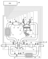
- FIG. 1 is an overall schematic configuration diagram of an internal combustion engine control system according to first and second embodiments of the present invention
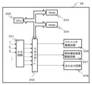
- FIG. 2 is a block diagram showing an example of a hardware configuration of an ECU according to the first and second embodiments of the present invention.
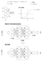
- FIG. 2 is a diagram illustrating an example of a neural network model according to the first embodiment of the present invention.
- 4 is a flowchart showing an example of an algorithm of an extended Kalman filter according to the first embodiment of the present invention.
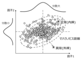
- FIG. 2 is a diagram showing an overview of Mahalanobis distance according to the first embodiment of the present invention.
- 5 is a diagram showing an example of actual behavior of the Mahalanobis distance according to the first embodiment of the present invention;
- FIG. 2 is a block diagram of state quantity estimation and Mahalanobis distance calculation according to the first embodiment of the present invention.
- 4 is a flowchart showing state quantity estimation and Mahalanobis distance calculation according to the first embodiment of the present invention.
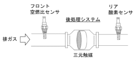
- FIG. 11 is a schematic diagram showing an example of the configuration of a post-processing system according to a second embodiment of the present invention.
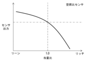
- FIG. 11 is a diagram illustrating the relationship between the equivalence ratio of exhaust gas and the output of an air-fuel ratio sensor according to a second embodiment of the present invention.
- FIG. 10 is a diagram illustrating the relationship between the equivalence ratio of exhaust gas and the output of a rear oxygen sensor according to a second embodiment of the present invention.
- FIG. 11 is a diagram illustrating the tendency of the equivalence ratio of H 2 O (water), CO (carbon monoxide), CO 2 (carbon dioxide), H 2 (hydrogen), and O 2 (oxygen) according to a second embodiment of the present invention.
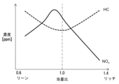
- FIG. 11 is a diagram illustrating the tendency of HC (hydrocarbon) and NOx (nitrogen oxides) with respect to the equivalence ratio according to a second embodiment of the present invention.
- FIG. 5 is a diagram illustrating a main reaction process of a three-way catalyst (ceria-based) used in a post-treatment system according to a second embodiment of the present invention.
- FIG. 11 is a diagram for explaining the tendency of the purification rate of a three-way catalyst with respect to the exhaust gas equivalence ratio at a temperature equal to or higher than the catalyst activation temperature according to a second embodiment of the present invention.
- 10A and 10B are diagrams illustrating the catalyst upstream equivalence ratio, the catalyst downstream equivalence ratio, and the output behavior of the rear oxygen sensor 22 according to the second embodiment of the present invention.
- FIG. 11 is a diagram illustrating the hysteresis of the output characteristic of a rear oxygen sensor according to a second embodiment of the present invention.
- FIG. 11 is a diagram illustrating the output of a rear oxygen sensor and the changes over time in the NOx concentration and HC concentration downstream of a catalyst according to a second embodiment of the present invention.
- FIG. 11 is a diagram illustrating the relationship between the degree of catalyst deterioration and the oxygen storage capacity of a three-way catalyst according to a second embodiment of the present invention.
- FIG. 11 is a diagram illustrating the relationship between the oxygen storage ratio of a three-way catalyst according to a second embodiment of the present invention and the NOx purification rate of the three-way catalyst.
- FIG. 11 is a diagram illustrating the results of a comparison of the catalyst upstream equivalence ratio, the catalyst downstream equivalence ratio, the oxygen storage ratio, and the output behavior of the rear oxygen sensor when a new catalyst and a degraded catalyst according to a second embodiment of the present invention are used.
- FIG. 11 is a block diagram of catalyst temperature estimation and Mahalanobis distance calculation according to a second embodiment of the present invention.
- 10 is a flowchart showing catalyst temperature estimation and Mahalanobis distance calculation according to a second embodiment of the present invention.
- FIG. 11 is a diagram illustrating an example of a neural network model according to a second embodiment of the present invention.
- FIG. 1 is a schematic diagram of an internal combustion engine control system 100 .
- the internal combustion engine control system 100 includes an internal combustion engine 1 and an ECU (Electronic Control Unit) 28 attached to the internal combustion engine 1.
- the ECU 28 is electrically connected to various sensors, actuators, etc. that constitute the internal combustion engine 1, and is an example of an internal combustion engine control device that controls the internal combustion engine 1.
- the internal combustion engine 1 is equipped with a flow sensor 2 (air flow sensor), turbocharger 3, air bypass valve 4, intercooler 5, boost temperature sensor 6, throttle valve 7, intake manifold 8, boost pressure sensor 9, flow enhancement valve 10, intake valve 11, valve opening/closing phase sensor 12, exhaust valve 13, valve opening/closing phase sensor 14, fuel injection valve 15, spark plug 16, knock sensor 17, crank angle sensor 18, wastegate valve 19, catalyst upstream air-fuel ratio sensor 20, exhaust purification catalyst (three-way catalyst) 21, rear oxygen sensor (catalyst downstream oxygen sensor) 22, EGR (Exhaust Gas Recirculation) pipe 23, EGR cooler 24, EGR valve 25, exhaust gas temperature sensor 26, differential pressure sensor 27, and catalyst downstream NOx sensor 29.
- the rear oxygen sensor 22 can be replaced with a catalyst downstream (rear) air-fuel ratio sensor (not shown).
- An intake air temperature sensor (not shown) is attached to the flow sensor 2 provided in the intake air flow path of the internal combustion engine 1.
- the intake air temperature sensor measures the intake air temperature.
- the turbocharger 3 is composed of a compressor 3a with compressor blades facing the intake passage, and a turbine 3b connected to the compressor 3a so as to rotate integrally with it and equipped with turbine blades facing the exhaust passage.
- the compressor 3a and turbine 3b are rotatably supported inside the turbocharger 3.
- the turbine 3b converts the energy of the exhaust gas from the internal combustion engine 1 into rotational energy.
- the compressor 3a connected to the turbine 3b compresses the intake air flowing in from the intake passage using the rotational energy of the turbine 3b.
- the intercooler 5 is provided downstream of the compressor 3a of the turbocharger 3, and cools the intake air temperature that has been increased by adiabatic compression by the compressor 3a.
- the supercharged temperature sensor 6 is installed downstream of the intercooler 5, and measures the temperature of the intake air cooled by the intercooler 5 (supercharged temperature).
- the throttle valve 7 is provided downstream of the intercooler 5 and narrows the intake flow path to control the amount of intake air flowing into the cylinder of the internal combustion engine 1.
- the throttle valve 7 is an electronically controlled butterfly valve whose valve opening can be controlled by the ECU 28. Downstream of the throttle valve 7 is connected to an intake manifold 8 to which a boost pressure sensor 9 is attached.
- the intake manifold 8 located downstream of the throttle valve 7 may be integrated with the intercooler 5. In this case, the volume from downstream of the compressor 3a to the cylinder can be reduced, improving acceleration/deceleration responsiveness and controllability.
- the air bypass valve 4 is disposed in the intake bypass flow passage that connects the upstream and downstream of the compressor 3a in the intake flow passage to prevent an excessive increase in pressure from the downstream of the compressor 3a to the upstream of the throttle valve 7. For example, if the throttle valve 7 is suddenly closed in a supercharged state, the air bypass valve 4 is opened under the control of the ECU 28, and the compressed intake air downstream of the compressor 3a is reversed through the bypass flow passage to the upstream of the compressor 3a. As a result, the phenomenon known as surging can be prevented by immediately lowering the supercharging pressure, and damage to the compressor 3a is appropriately prevented.
- the flow enhancing valve 10 is located downstream of the intake manifold 8, and enhances the turbulence of the flow inside the cylinder by creating a bias in the intake air drawn into the cylinder.
- the ECU 28 can close the flow enhancing valve 10 to promote turbulent combustion and stabilize the combustion that occurs in the combustion chamber.
- the intake valve 11 and exhaust valve 13 each have a variable valve mechanism for continuously varying the valve opening and closing phase.
- Valve opening and closing phase sensors 12, 14 for detecting the valve opening and closing phase are respectively attached to the variable valve mechanisms of the intake valve 11 and exhaust valve 13.
- Each cylinder of the internal combustion engine 1 is provided with a direct injection type fuel injection valve 15 that injects fuel pressurized by a fuel pump (not shown) into the combustion chamber of the cylinder.
- the fuel injection valve 15 may be of a port injection type that injects fuel into the intake flow path. Alternatively, multiple direct injection type and port injection type fuel injection valves 15 may be used in combination for each cylinder.
- the cylinders of the internal combustion engine 1 are fitted with spark plugs 16 that expose their electrodes inside the cylinders and ignite the combustible mixture with a spark.
- a knock sensor 17 is provided in the cylinder block and detects the presence or absence of knock by detecting cylinder block vibrations caused by combustion pressure vibrations that occur in the combustion chamber.
- a crank angle sensor 18 is fitted near the crankshaft and outputs a signal to the ECU 28 according to the rotation angle of the crankshaft.
- the upstream air-fuel ratio sensor (catalyst upstream air-fuel ratio sensor 20) is disposed downstream of the turbine 3b of the turbocharger 3 and upstream of a three-way catalyst (exhaust purification catalyst 21) that has oxygen storage capacity and is provided in the exhaust pipe.
- the upstream air-fuel ratio sensor detects the exhaust gas composition detected from the exhaust gas, i.e., the catalyst upstream air-fuel ratio of the exhaust gas, and outputs a signal indicating the catalyst upstream air-fuel ratio to the ECU 28.
- the exhaust purification catalyst 21 is an example of a three-way catalyst and is provided downstream of the catalyst upstream air-fuel ratio sensor 20.
- the exhaust purification catalyst 21 purifies harmful exhaust gas components such as carbon monoxide, nitrogen compounds, and unburned hydrocarbons in the exhaust gas by catalytic reaction.
- the rear oxygen sensor 22 is disposed downstream of the exhaust purification catalyst 21.
- the rear oxygen sensor 22 detects the amount of oxygen contained in the exhaust gas after purification by the exhaust purification catalyst 21.
- the exhaust purification catalyst 21 is also called a three-way catalyst or a catalyst.
- the turbocharger 3 is equipped with an air bypass valve 4 and a wastegate valve 19.
- the air bypass valve 4 is arranged on the bypass flow path connecting the upstream and downstream of the compressor 3a to prevent an excessive increase in pressure from the downstream of the compressor 3a to the upstream of the throttle valve 7. If the throttle valve 7 is suddenly closed in a supercharged state, the air bypass valve 4 is opened under the control of the ECU 28, and the compressed intake air downstream of the compressor 3a is reversed through the bypass flow path to the upstream of the compressor 3a. As a result, the phenomenon known as surging can be prevented by immediately lowering the supercharging pressure, and damage to the compressor 3a is appropriately prevented.
- the wastegate valve 19 is disposed in the exhaust bypass flow passage that connects the upstream and downstream of the turbine 3b in the exhaust flow passage.
- the wastegate valve 19 is an electrically operated valve whose valve opening can be freely controlled according to the boost pressure under the control of the ECU 28.
- the opening of the wastegate valve 19 is adjusted by the ECU 28 based on the boost pressure detected by the boost pressure sensor 9, part of the exhaust gas passes through the bypass flow passage, thereby reducing the energy that the exhaust gas imparts to the turbine 3b.
- the wastegate valve 19 can adjust the boost pressure to the target pressure.
- the EGR pipe 23 connects the exhaust flow path downstream of the exhaust purification catalyst 21 with the intake flow path upstream of the compressor 3a, and diverts exhaust gas from downstream of the exhaust purification catalyst 21 and returns it to the upstream of the compressor 3a.
- the EGR cooler 24 provided in the EGR pipe 23 cools the diverted exhaust gas.
- the EGR valve 25 is provided in the EGR pipe 23 between the EGR cooler 24 and the upstream of the compressor 3a, and controls the flow rate of exhaust gas returned to the upstream of the compressor 3a.
- the EGR pipe 23 is also provided with an exhaust gas temperature sensor 26 that detects the exhaust gas temperature of the exhaust gas upstream of the EGR valve 25, and a differential pressure sensor 27 that detects the differential pressure between the upstream and downstream of the EGR valve 25.
- the ECU 28 is a control device that includes a CPU (Central Processing Unit) 205, a ROM (Read Only Memory) 204, a RAM (Random Access Memory) 203, as well as an A/D (Analog-to-Digital) converter and a driver circuit (not shown) shown in FIG. 2 (described later), and controls each component of the internal combustion engine 1 and executes various data processing.
- the ECU 28 controls the operation of actuators such as the throttle valve 7, the fuel injection valve 15, the variable valve mechanisms of the intake valve 11 and the exhaust valve 13, and the EGR valve 25.
- the ECU 28 also detects the operating state of the internal combustion engine 1 based on signals input from various sensors, and ignites the spark plug 16 at a timing determined according to the operating state.
- FIG. 2 is a block diagram showing an example of the hardware configuration of the ECU 28.
- the ECU 28 includes an input circuit 201, an input/output port 202, a RAM 203, a ROM 204, a CPU 205, a throttle valve drive circuit 206, a fuel injection valve drive circuit 207, and an ignition output circuit 208.
- Output signals from various sensors are input to the input circuit 201.
- FIG. 2 an example is shown in which output signals from the throttle sensor of the throttle valve 7, the flow sensor 2, the boost temperature sensor 6, the boost pressure sensor 9, the valve opening/closing phase sensors 12, 14, the knock sensor 17, the crank angle sensor 18, the catalyst upstream air-fuel ratio sensor 20, and the rear oxygen sensor 22 are input to the input circuit 201 of the ECU 28.
- the signals input to the input circuit 201 are sent to the input/output port 202.
- the signal sent to the input/output port 202 is stored in the RAM 203 and processed by the CPU 205.
- a control program describing the contents of the processing is written in advance in the ROM 204 and executed by the CPU 205.
- the ROM 204 records programs and data necessary for the operation of the CPU 205, and is used as an example of a computer-readable non-transitory storage medium that stores a program executed by the ECU 28.
- the control signals calculated by the CPU 205 according to the control program are output to each device such as the throttle valve drive circuit 206, the fuel injection valve drive circuit 207, and the ignition output circuit 208.
- the throttle valve drive circuit 206 outputs a drive signal to the throttle valve 7 to control the opening and closing drive of the throttle valve 7.
- the fuel injection valve drive circuit 207 outputs a drive signal to the fuel injection valve 15 to control the opening and closing of the fuel injection valve 15 at the fuel injection timing.
- the ignition output circuit 208 outputs a drive signal to the ignition output circuit 208 to control the ignition of the spark plug 16 at the ignition timing.
- a neural network model is a mathematical model that mimics the structure of the neural circuits in the human brain, and each neuron that makes up the model has a weight and bias set.
- activation functions are also defined for neurons. Activation functions can be set appropriately, such as logistic functions or ramp functions. A layer is formed from multiple neurons, and an intermediate layer is set between the input layer and the output layer. By increasing the number of neurons and the number of intermediate layers, it is possible to approximate more complex input-output relationships. There is a trade-off between approximation accuracy and model size, and a balance point that satisfies both requirements is selected. For example, the frequency of the exhaust gas sensor signal is set in the input layer, and catalyst deterioration diagnosis is set in the output layer, and the input-output relationship can be approximated by machine learning (with a teacher) of the weights and biases of each neuron. The backpropagation method can be applied as a machine learning algorithm.
- Fig. 4 is a flowchart showing an example of an extended Kalman filter algorithm.
- the algorithm and the method of application to the present control of the extended Kalman filter which is one of the components of the present invention, are described below.
- the algorithm and the method of application to the present control of the extended Kalman filter are described below.
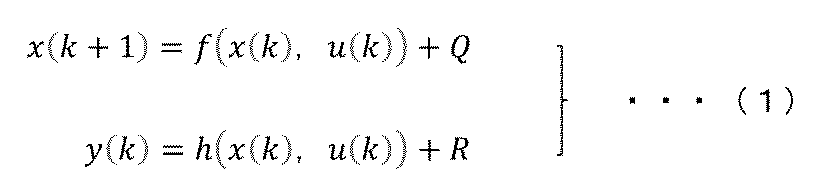
- the extended Kalman filter is based on the assumption that the state-output equations include the system noise Q and the observation noise R defined in equations (1) and (2).
- F k (k) and H k (k) are the Jacobian matrices with respect to the state variables of f and h, respectively.
- the extended Kalman filter algorithm consists of a prediction step and a filtering step.
- the prediction step the internal state variable vector and covariance matrix are updated based on the input variables and system noise using the following equation:
- FIG. 5 shows an overview of Mahalanobis distance.
- the Mahalanobis distance has the advantage that it is easy to determine whether a value is normal or abnormal, even if the distance from the center point is similar, due to the combination of multidimensional variance. Mahalanobis distance is calculated using the following formula.
- x represents the input data vector as shown in formula (7).
- ⁇ represents the average value vector as shown in formula (8).
- Equation (9) shows the variance-covariance matrix.
- E is the expected value.
- Equation (10) calculates the Mahalanobis distance D M.
- Figure 6 shows an example of the actual behavior of the Mahalanobis distance.
- the control input u is in the interpolation region, and in interval (b), it is in the extrapolation region.
- interval (c) the sensor used in the extended Kalman filter is abnormal, and an abnormal sensor value is input.
- the behavior of the Mahalanobis distance for each interval will be explained.
- the control input u is in the interpolation region and the sensor is operating normally, so the Mahalanobis distance is small and the estimation accuracy is good.
- interval (b) the control input u is in the extrapolation region, so the Mahalanobis distance increases and the estimation accuracy is worse than in interval (a).
- interval (c) the control input u is in the interpolation region, but the sensor used in the extended Kalman filter is outputting an abnormal value, so the Mahalanobis distance increases and the estimation accuracy is worse than in interval (a). In this way, when the control input or sensor is operating abnormally, the Mahalanobis distance increases, and the estimation accuracy is worse than in interval (a). In this way, the reliability of the estimate of the state observer can be judged by the increase in the Mahalanobis distance.
- an arbitrary input value input from the ECU is input to the extended Kalman filter 701.
- the input value includes a control value and a sensor value.
- the state quantity is estimated using the input value.
- the state quantity is a differential value, an integral calculation is performed using a specified time interval value and a previous value state quantity to obtain a current state quantity.
- the same type of input value as that of the extended Kalman filter 701 is also input to the Mahalanobis distance calculation unit 702.
- the Mahalanobis distance for the current input is calculated using the input value.
- a comparison unit 703 compares the calculated Mahalanobis distance with a specified threshold value.
- the current Mahalanobis distance is greater than the threshold value, 0 is output and it is deemed to be outside the learning range or the sensor is broken. If the current Mahalanobis distance is smaller than the threshold value, 1 is output and it is determined to be within the learning range or the sensor is normal. Then, the result of the extrapolation is recorded.
- 0 is input to the switching unit 704, it is assumed that the extended Kalman filter 701 is operating outside the learning range or the sensor is broken and normal estimation calculation is not possible, and a specified steady value is output.
- 1 is input, it is assumed that the extended Kalman filter 701 is operating within the learning range or the sensor is operating normally and normal estimation calculation is possible, and an estimated state quantity is output.
- step 801 a control input and a sensor input value are received from the ECU.
- step 802 a Mahalanobis distance is calculated using the control input and the sensor input value from the ECU.
- step 803 the threshold value specified in step 802 is compared with the calculated Mahalanobis distance. If it is smaller than the threshold value, the process proceeds to step 804, and if it is larger than the threshold value, the process proceeds to step 805.
- step 804 the extended Kalman filter is operating within the learning range or the sensor is operating normally, so the state quantity (differential value) is estimated by the extended Kalman filter using the control input and the sensor input value from the ECU, and an integral calculation is performed using the specified time step value and the previous value state quantity to obtain the current state quantity.
- step 805 the extended Kalman filter is operating outside the learning range or the sensor is malfunctioning, so the diagnosis result is recorded and used as sensor malfunction or re-learning data.
- step 806 an estimated value calculated using a physical formula or a substitute value such as the output value of the MAP defined at the operating point is output.
- FIG. 9A is a schematic diagram showing an example configuration of the post-processing system 110.
- a three-way catalyst is used as the exhaust gas purification catalyst (exhaust purification catalyst 21).
- a catalyst upstream air-fuel ratio sensor 20 is provided upstream of the three-way catalyst, and a rear oxygen sensor 22 is provided downstream, with the catalyst upstream air-fuel ratio sensor 20 and the rear oxygen sensor 22 being connected to a control device such as an ECU 28.
- the ECU 28 measures the catalyst upstream air-fuel ratio of the exhaust gas flowing into the three-way catalyst via the catalyst upstream air-fuel ratio sensor 20, and can detect the amount of oxygen contained in the exhaust gas after catalytic purification via the rear oxygen sensor 22.
- the horizontal axis of FIG. 9B represents the equivalence ratio, and the vertical axis represents the output of the catalyst upstream air-fuel ratio sensor 20.
- the output of the catalyst upstream air-fuel ratio sensor 20 (air-fuel ratio sensor output) tends to decrease as the equivalence ratio increases (in other words, as the exhaust gas becomes richer).
- the ECU 28 converts the catalyst upstream air-fuel ratio sensor signal into the catalyst upstream air-fuel ratio based on the relationship between the equivalence ratio of the exhaust gas and the output of the catalyst upstream air-fuel ratio sensor 20. This enables the ECU 28 to accurately detect the catalyst upstream air-fuel ratio over a wide range, from lean to rich exhaust gas conditions.
- FIG. 9C is a diagram illustrating the relationship between the equivalence ratio of exhaust gas and the output of the rear oxygen sensor 22.
- the horizontal axis of FIG. 9C represents the equivalence ratio, and the vertical axis represents the rear oxygen sensor output.
- the rear oxygen sensor output which can also be interpreted as the rear oxygen sensor voltage, changes depending on the electromotive force caused by the difference in concentration between the oxygen concentration in the exhaust gas and the oxygen concentration in the air.
- the rear oxygen sensor output generally exhibits a minimum electromotive force under lean conditions and a maximum electromotive force under rich conditions. Therefore, in catalyst control, the rear oxygen sensor output has the characteristic of suddenly changing at the theoretical air-fuel ratio (equivalence ratio 1.0). By capturing the timing of this change in the rear oxygen sensor output, the ECU 28 can detect the amount of oxygen in the exhaust gas released downstream of the three-way catalyst.
- 10A and 10B are diagrams illustrating the tendency of the concentration of chemical species in the exhaust gas relative to the equivalence ratio.
- FIG. 10A is a diagram illustrating the trend for the equivalence ratio of H 2 O (water), CO (carbon monoxide), CO 2 (carbon dioxide), H 2 (hydrogen), and O 2 (oxygen).
- Figure 10B is a diagram that explains the tendency of HC (hydrocarbons) and NOx (nitrogen oxides) with respect to the equivalence ratio.
- the horizontal axis of Figures 10A and 10B is the equivalence ratio, and the vertical axis is the concentration of the chemical species in the exhaust gas.
- the combustion gas composition of a hydrocarbon fuel shows a tendency that CO (carbon monoxide) and H2 (hydrogen) increase on the rich side of the stoichiometric air-fuel ratio, and O2 (oxygen) increases on the lean side.
- NOx nitrogen oxides
- NOx shows a maximum value on the slightly lean side of the stoichiometric air-fuel ratio, and shows a tendency to decrease on the lean side and rich side.
- HC unburned hydrocarbons
- the air-fuel ratio becomes excessively lean or rich beyond the stoichiometric air-fuel ratio, the amount of HC discharged due to incomplete combustion of the fuel tends to increase.
- Fig. 11 is a diagram for explaining the main reaction process of the three-way catalyst (ceria-based) used in the aftertreatment system 110. In the reaction process shown in Fig. 11, coefficients are omitted.
- the three-way catalytic reaction process mainly consists of oxidation reaction, NOx reduction reaction, and oxygen storage and release reaction.
- oxidation reaction CO, H2 , and HC produced under rich or high temperature conditions react with oxygen to produce harmless CO2 and H2O .
- Unburned hydrocarbons (HC) include components such as methane, propane, ethylene, and butane, and each reaction proceeds at a different speed.
- the NOx reduction reaction is mainly represented by the reaction of CO with NO, and CO2 and N2 are produced.
- the storage/release of oxygen (O 2 ) and the oxidation/reduction reactions of HC, CO, and NO proceed via the catalytic material Ce (cerium). That is, CO 2 and H 2 O are generated by the reaction of cerium dioxide (CeO 2 ) with CO and HC, and N2 is generated by the reaction of cerium trioxide (Ce 2 O 3 ) with NO.
- the oxygen storage ratio ⁇ of the three-way catalyst is determined by the balance between CeO 2 and Ce 2 O 3 that are generated at the same time. That is, if all Ce 2 O 3 in the catalyst becomes CeO 2 , it cannot react with NO, and NO cannot be purified.
- the ECU 28 needs to properly manage the catalyst temperature so that the catalyst temperature reaches or exceeds the activation temperature as soon as possible after the internal combustion engine 1 is started.
- the system shown in this embodiment is configured to use a ceria-based three-way catalyst, but the present invention is not limited to this. Even with catalysts using other materials that exhibit similar effects, the same effects can be achieved without changing the configuration of the invention by adjusting the constants of the control model.
- the catalytic reaction may involve water-gas shift reactions and the like.
- the ECU 28 can also accommodate these reaction mechanisms by adjusting the control model constants.
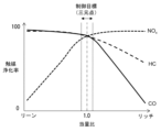
- Figure 12 is a diagram that explains the tendency of the purification rate of a three-way catalyst versus the exhaust gas equivalence ratio at or above the catalyst activation temperature.
- the horizontal axis of Figure 12 is the equivalence ratio, and the vertical axis is the catalyst purification rate.
- Figure 12 also shows the catalyst purification rates for NOx, HC, and CO when the equivalence ratio changes from lean to rich. Also, the closer the catalyst purification rate is to 100%, the more the components in the exhaust gas are purified and the less the components in the exhaust gas are emitted.
- This graph shows that the purification rate characteristics of the three-way catalyst change at the boundary of the theoretical air-fuel ratio (the "control target" in the diagram).
- the purification rates of CO and HC are maintained at approximately 90% or more, while the NOx purification rate decreases as the equivalence ratio decreases.
- the purification rates of HC and CO are maintained at approximately 90% or more, while the NOx purification rate decreases as the equivalence ratio decreases.
- the purification rates of HC and CO In the vicinity of the theoretical air-fuel ratio, purification rates of 90% or more for NOx, HC, and CO can all be achieved.
- the ECU 28 controls the purification rate of the three-way catalyst to be high by maintaining the equivalence ratio at the theoretical air-fuel ratio, which is the three-way point.
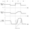
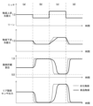
- FIG. 13 is a diagram for explaining the catalyst upstream equivalence ratio, catalyst downstream equivalence ratio, and output behavior of the rear oxygen sensor 22.
- the horizontal axis of FIG. 13 is time, and the vertical axis is the catalyst upstream equivalence ratio, catalyst downstream equivalence ratio, and rear oxygen sensor output.
- the equivalence ratio downstream of the catalyst (catalyst downstream air-fuel ratio) and the output behavior of the rear oxygen sensor 22 installed downstream of the catalyst are shown when the catalyst upstream equivalence ratio (catalyst upstream air-fuel ratio) is suddenly changed in a stepwise manner (step-like manner) to the lean side or rich side with the equivalence ratio at 1.0 as the center.
- the rear oxygen sensor output after a relaxation time required for the catalyst downstream equivalence ratio to be gradually increased, changes to a predetermined maximum electromotive force value side under rich conditions.
- time period (d) in FIG. 13 when the catalyst upstream equivalence ratio is decreased again from an equivalence ratio of 1.0 to be changed to the lean side in a stepwise manner, the catalyst downstream equivalence ratio gradually decreases again to the lean side.
- the rear oxygen sensor output which responds to the change in the catalyst upstream equivalence ratio, changes again to the predetermined minimum electromotive force value under lean conditions after the relaxation time required for the catalyst downstream equivalence ratio to gradually decrease has passed.
- the time required for the catalyst downstream equivalence ratio to change from rich to lean during this time period (d) is shorter than the time required for it to change from lean to rich during time period (c), and is characterized by a so-called hysteresis characteristic.
- the delay time of the catalyst downstream equivalence ratio and the delay time of the output of the rear oxygen sensor 22 tend to differ when changing from lean to rich and when changing from rich to lean.
- This tendency is due to the fact that the reaction speed of the oxygen storage and release reaction of CeO2 and Ce2O3 in the three-way catalyst (ceria-based) described in Figure 11 differs when changing from rich to lean and when changing from lean to rich.
- the reaction speed of the three-way catalyst also depends on the catalyst temperature and exhaust gas flow rate, so the above-mentioned hysteresis changes depending on the catalyst temperature and exhaust gas flow rate.
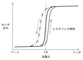
- FIG. 14 is a diagram for explaining the hysteresis of the output characteristics of the oxygen sensor.
- the equivalence ratio is plotted on the horizontal axis
- the oxygen sensor output is plotted on the vertical axis.
- the static characteristics of the oxygen sensor are as explained with reference to FIG. 9C.
- the oxygen sensor also uses the above-mentioned catalytic material. Therefore, the dynamic characteristics of the oxygen sensor have a hysteresis characteristic in which the change from rich to lean differs from the change from lean to rich.
- the relaxation time required for the oxygen sensor signal to change from the predetermined maximum electromotive force value side under rich conditions to the predetermined minimum electromotive force value side under lean conditions is shorter than the relaxation time required for the oxygen sensor signal to change from the predetermined minimum electromotive force value side under lean conditions to the predetermined maximum electromotive force value side under rich conditions.
- the behavior of the oxygen sensor signal described above is affected by changes in the material properties constituting the oxygen sensor during use and by the temperature of the oxygen sensor.
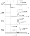
- FIG. 15 is a diagram for explaining the output of the rear oxygen sensor 22 and the time change of the NOx concentration and HC concentration downstream of the catalyst.
- the vertical axis is the catalyst upstream equivalence ratio, the rear oxygen sensor output, the catalyst downstream NOx concentration, and the catalyst downstream HC concentration.
- the change (relaxation time) of the rear oxygen sensor output from the intermediate state of the catalyst upstream equivalence ratio of 1.0 to the lean side is different from the change from the lean side to the intermediate state of the catalyst upstream equivalence ratio of 1.0. That is, the relaxation time required for the oxygen sensor signal to change from the predetermined minimum electromotive force value side under the lean condition due to fuel cut to the intermediate state under the stoichiometry control condition (see time period (a) in Fig. 15) is longer than the relaxation time required for the oxygen sensor signal to change from the intermediate state under the stoichiometry control condition to the predetermined minimum electromotive force value side under the lean condition.
- the air-fuel ratio control of the internal combustion engine 1 it is necessary to perform rich correction control with an appropriate correction amount and period, taking into account the state inside the catalyst.
- the rear oxygen sensor signal that detects the oxygen state of the exhaust gas downstream of the catalyst can be used as a judgment criterion.
- Fig. 15 the output of the rear oxygen sensor 22 and the changes over time in the NOx concentration and HC concentration downstream of the catalyst when stoichiometry control is performed are shown by solid lines.
- the output of the rear oxygen sensor 22 increases with a delay when the mixture changes from a lean state to a rich state.
- the NOx concentration downstream of the catalyst exhibits a behavior in which NOx that momentarily increases is discharged during the delay period until the output of the rear oxygen sensor 22 returns to normal.
- the HC concentration downstream of the catalyst remains almost unchanged, so HC emissions are prevented.
- FIG. 15 the output of the rear oxygen sensor 22 and the changes over time in the NOx concentration and HC concentration downstream of the catalyst when appropriate rich correction is performed are shown by dashed lines.
- the equivalence ratio upstream of the catalyst becomes rich.
- the output of the rear oxygen sensor 22 reaches the equivalence ratio earlier than stoichiometry control. Furthermore, since the NOx concentration and HC concentration downstream of the catalyst are almost unchanged, the emission of NOx and HC is prevented.
- Figure 16 is a diagram that explains the relationship between the degree of catalyst deterioration and the oxygen storage capacity (OSC: Oxygen Storage Capacity) of a three-way catalyst.
- the horizontal axis of Figure 16 is the degree of catalyst deterioration, and the vertical axis is the oxygen storage capacity.
- Catalyst deterioration refers to a state in which the catalytic action of a three-way catalyst is reduced due to thermal effects and poisoning from sulfur contained in the fuel.
- the oxygen storage capacity of a three-way catalyst is roughly proportional to the degree of catalyst deterioration in the left-right direction in Figure 16. In other words, as catalyst deterioration progresses, the oxygen storage capacity of the three-way catalyst tends to decrease.
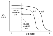
- FIG. 17 is a diagram for explaining the relationship between the oxygen storage ratio of the three-way catalyst, that is, the value obtained by dividing the current oxygen storage amount of the three-way catalyst by the above-mentioned oxygen storage capacity, and the NOx purification rate.
- the horizontal axis of FIG. 17 is the oxygen storage ratio, and the vertical axis is the NOx purification rate.
- the change in the NOx purification rate of a new three-way catalyst is represented by a solid line
- the change in the NOx purification rate of a deteriorated three-way catalyst is represented by a dashed line.
- the new three-way catalyst has a higher NOx purification rate than the deteriorated three-way catalyst.
- the NOx purification rate of both the new three-way catalyst and the deteriorated three-way catalyst tends to deteriorate rapidly. This is because, as explained with reference to Fig. 11, Ce2O3 in the catalyst is important for purifying NOx , and if all Ce2O3 reacts and turns into CeO2 , Ce2O3 cannot react with NO and cannot purify NOx .
- the oxygen storage ratio for the same oxygen storage amount increases as a result.
- the NOx purification rate value for the oxygen storage amount is lower for a deteriorated three-way catalyst, shown by the dashed line in FIG. 18, than for a new three-way catalyst, shown by the solid line in FIG. 18. Therefore, in order to maintain a high NOx purification rate, it is necessary not only to maintain the exhaust gas air-fuel ratio at the catalyst inlet at the three-way point, but also to appropriately correct and control the exhaust gas air-fuel ratio at the catalyst inlet so that the oxygen storage rate is within a range in which a predetermined NOx purification rate can be obtained, taking into account the state inside the catalyst, which cannot be directly observed from the outside, that is, the current oxygen storage capacity and oxygen storage rate of the three-way catalyst.
- the predetermined range of oxygen storage rate is represented by the deteriorated control range 36 when the catalyst is deteriorated, and the new control range 35 when the catalyst is new, as shown in FIG. 17, and the new control range 35 is wider than the deteriorated control range 36.
- the extended Kalman filter 1901 receives control inputs such as exhaust gas flow rate and equivalence ratio from the ECU, and sensor inputs such as an exhaust gas temperature sensor that detects the exhaust gas temperature downstream of the catalyst, and based on these inputs, the extended Kalman filter 1901 calculates the time differential value of the catalyst temperature. After that, an integral calculation is performed using a specified time interval value and a previous value state quantity to calculate the current catalyst temperature. At the same time, the same type of input value as that of the extended Kalman filter 1901 is also input to the Mahalanobis distance calculation unit 1902. The Mahalanobis distance for the current input is calculated using the input value.
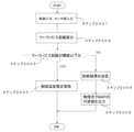
- step 2001 the control input and sensor input value are received from the ECU.
- step 2002 the Mahalanobis distance is calculated using the control input and sensor input value from the ECU.
- step 2003 the Mahalanobis distance calculated is compared with the threshold value specified in step 2002. If it is smaller than the threshold value, proceed to step 2004, and if it is larger than the threshold value, proceed to step 2005.
- step 2004 the extended Kalman filter is operating within the learning range or the sensor is operating normally, so the catalyst temperature (differential value) is estimated by the extended Kalman filter using the control input and sensor input value from the ECU, and an integral calculation is performed using the specified time step value and the previous value state quantity to calculate the current catalyst temperature.
- step 2005 the extended Kalman filter is operating outside the learning range or the sensor is malfunctioning, so the diagnosis result is recorded and used as sensor malfunction or re-learning data.
- step 2006 alternative values such as estimated values calculated using physical formulas and MAP output values defined at the operating point are output.
- the processor (CPU 205, Figure 2) of the control device (ECU 28, Figure 1) calculates the state variable (e.g., catalyst temperature) at the second timing from the vehicle's state variable at the first timing (e.g., previous value of catalyst temperature, Figure 19), the vehicle's control input at the second timing after the first timing (e.g., exhaust gas flow rate, equivalence ratio, Figure 19), and the observation value at the second timing detected by the vehicle's sensor (sensor input: e.g., exhaust gas temperature downstream of the catalyst, Figure 19).
- state variable e.g., catalyst temperature
- the processor approximates a state space model consisting of a state equation (first equation in Equation (1)) for the state variable (e.g., catalyst temperature) and an observation equation (second equation in Equation (1)) for the observation value (e.g., exhaust gas temperature downstream of the catalyst) using a neural network model.
- the processor determines the reliability (accuracy) of the state variable (e.g., catalyst temperature) at the second timing from an index (e.g., Mahalanobis distance) based on the control input (e.g., exhaust gas flow rate, equivalence ratio) at the second timing and the observation value (e.g., exhaust gas temperature downstream of the catalyst) at the second timing.
- the observation value is a sensor value that is correlated with the state variable (the second equation in equation (1)).
- the processor determines that the reliability of the state variable at the second timing (e.g., catalyst temperature) is low (comparison unit 1903, FIG. 19). Note that in the second embodiment, if the Mahalanobis distance is greater than a threshold value, the reliability of the state variable at the second timing (e.g., catalyst temperature) is determined to be low, and 0 is output from comparison unit 1903.
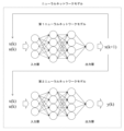
- the neural network model is composed of a first neural network model having an input layer to which the state variable x(k) at the first timing and the control input u(k) at the first timing are input, and an output layer to which the state variable x(k+1) at the second timing is output, and a second neural network model having an input layer to which the state variable x(k) at the first timing and the control input u(k) at the first timing are input, and an output layer to which the observation value y(k) at the first timing is output.
- the processor (CPU 205) inputs the state variable of the first timing (e.g., the previous value of the catalyst temperature), the control input of the second timing (e.g., exhaust gas flow rate, equivalence ratio), and the observation value of the second timing (sensor input: e.g., exhaust gas temperature downstream of the catalyst) to the extended Kalman filter 1901, and obtains the time derivative value (state quantity) of the state variable from the extended Kalman filter 1901.
- the processor (CPU 205) integrates the time derivative value (state quantity) of the state variable, and adds the integrated value to the state variable of the first timing (e.g., the previous value of the catalyst temperature), thereby calculating the state variable of the second timing (e.g., catalyst temperature).
- the processor (CPU 205) If the Mahalanobis distance is equal to or less than the threshold, the processor (CPU 205) outputs the state variable (e.g., catalyst temperature) at the second timing calculated using the extended Kalman filter 1901. If the Mahalanobis distance is greater than the threshold, the processor (CPU 205) does not output the state variable (e.g., catalyst temperature) at the second timing calculated using the extended Kalman filter 1901, but outputs an alternative value derived from a physical formula or a map as the state variable (e.g., catalyst temperature) (step 2006, FIG. 20).
- the state variable e.g., catalyst temperature
- the processor performs machine learning using the state variables at the first timing (e.g., the previous value of the catalyst temperature) calculated using the extended Kalman filter 1901, the control inputs at the first timing (e.g., exhaust gas flow rate, equivalence ratio), and the state variables at the second timing (e.g., catalyst temperature) calculated using the extended Kalman filter 1901 as training data for a first neural network model.
- the first timing e.g., the previous value of the catalyst temperature
- the control inputs at the first timing e.g., exhaust gas flow rate, equivalence ratio
- the state variables at the second timing e.g., catalyst temperature
- the processor (CPU 205) also performs machine learning using the state variables at the first timing (e.g., the previous value of the catalyst temperature) calculated using the extended Kalman filter 1901, the control inputs at the first timing (e.g., exhaust gas flow rate, equivalence ratio), and the observation values at the first timing (e.g., exhaust gas temperature downstream of the catalyst) as training data for a second neural network model.
- the state variables at the first timing e.g., the previous value of the catalyst temperature
- the extended Kalman filter 1901 e.g., the control inputs at the first timing (e.g., exhaust gas flow rate, equivalence ratio)
- the observation values at the first timing e.g., exhaust gas temperature downstream of the catalyst
- the processor (CPU 205) performs machine learning if the Mahalanobis distance is equal to or less than the threshold, and does not perform machine learning if the Mahalanobis distance is greater than the threshold.
- the above-mentioned embodiment describes the system configuration in detail and specifically in order to explain the present invention in an easy-to-understand manner, and is not necessarily limited to having all of the configurations described.
- control lines and information lines shown are those considered necessary for the explanation, and do not necessarily show all control lines and information lines on the product. In reality, it can be assumed that almost all components are interconnected.
- each of the above configurations, functions, etc. may be realized in hardware, for example by designing some or all of them as an integrated circuit. Furthermore, each of the above configurations, functions, etc. may be realized in software by a processor interpreting and executing a program that realizes each function. Information such as the programs, tables, files, etc. that realize each function can be stored in a memory, a recording device such as a hard disk or SSD (Solid State Drive), or a recording medium such as an IC card, SD card, or DVD.
- a recording device such as a hard disk or SSD (Solid State Drive)
- a recording medium such as an IC card, SD card, or DVD.
- the present invention may take the following forms:
- a powertrain system control device for an automobile equipped with a sensor for detecting a current state having an index value setting unit that determines an abnormality diagnosis index based on the control input and the sensor detection value as an index for determining the validity of the state estimation amount and a judgment threshold based on the state variables related to the automobile detected by the sensor, a control input for controlling the automobile, and a state estimation amount estimated by a state observer, the state observer having a neural network model that approximates a state space model having the sensor detection target as one of the output variables, and a means for determining the validity of the state quantity estimation result using the state observer based on the abnormality diagnosis index defined by the input of the neural network model and the sensor detection value.
- a powertrain system control device having a means for using a Mahalanobis distance as the abnormality diagnosis index defined by the control input and the sensor detection value.
- the powertrain system control device includes a means for determining the validity of the state quantity estimation result of the state observer based on the Mahalanobis distance.
- the powertrain system control device is provided with a means for performing state quantity estimation using an extended Kalman filter capable of considering nonlinearity as the state observer.
- a powertrain system control device as described in (1) that includes a means for stopping state quantity estimation using the extended Kalman filter when the Mahalanobis distance is equal to or greater than a predetermined value, diagnosing that the state quantity estimation or the sensor is abnormal, and notifying or recording the diagnosis result to the outside.
- the neural network model that approximates the state space model includes a transient neural network model that approximates a state space model that uses a previous value as one of the inputs.
- the powertrain system control device described in (1) is provided in which the extended Kalman filter calculates a time derivative value of the state quantity, adds it to the previous value, and estimates the current state quantity.
- the powertrain system control device further comprising: outputting an alternative value calculated from a physical formula or a map after terminating state quantity estimation using the extended Kalman filter when the Mahalanobis distance is equal to or greater than a predetermined value.
- the validity/invalidity of the transient neural network model and the sensor can be diagnosed with a minimum of information and calculations, making it possible to guarantee the reliability of the control software.
- 1...internal combustion engine 20...catalyst upstream air-fuel ratio sensor, 21...exhaust gas purification catalyst, 22...rear oxygen sensor, 28...ECU, 51...exhaust gas flow rate calculation section, 52...catalyst upstream state quantity estimation section, 53...catalyst downstream state quantity estimation section, 54...correction section, 55...NOx sensor diagnosis section, 56...fuel injection amount correction section, 56a...fuel injection amount correction map, 57...fuel composition discrimination section, 100...internal combustion engine control system, 110...aftertreatment system
Landscapes
- Engineering & Computer Science (AREA)
- Chemical & Material Sciences (AREA)
- Combustion & Propulsion (AREA)
- Mechanical Engineering (AREA)
- General Engineering & Computer Science (AREA)
- Artificial Intelligence (AREA)
- Evolutionary Computation (AREA)
- Electrical Control Of Air Or Fuel Supplied To Internal-Combustion Engine (AREA)
- Combined Controls Of Internal Combustion Engines (AREA)
Abstract
Description
図1は、内燃機関制御システム100の全体概略構成図である。
図2は、ECU28のハードウェア構成例を示すブロック図である。
図3にニューラルネットワークの概要を示す。ニューラルネットワークモデルとは、人間の脳神経回路の仕組みを模した数学モデルであり、モデルを構成する各ニューロンには、重みとバイアスが設定されている。
図4は、拡張カルマンフィルタアルゴリズムの例を示すフローチャートである。本発明の構成要素の一つである拡張カルマンフィルタについて、アルゴリズムおよび本制御への適用方法を述べる。拡張カルマンフィルタについて、アルゴリズムおよび本制御への適用方法を述べる。拡張カルマンフィルタでは、式(1)、(2)で定義したシステムノイズQおよび観測ノイズRを含む状態・出力方程式を前提に考える。





基づき、直接測定困難な内部状態変数を推定することができる。
図5にマハラノビス距離の概要図を示す。マハラノビス距離は多次元の分散の組み合わせにより、中心点からの距離が同様であっても、正常値または異常値の判定をし易いという特徴がある。マハラノビス距離は次式で算出する。x は式(7)のように入力データベクトルを示す。またμ は式(8)のように平均値ベクトルを示す。




次に図8を用いて本実施例のフローチャートについて説明する。ステップ801にて、ECUから制御入力及びセンサ入力値を受信する。ステップ802にて、ECUから制御入力及びセンサ入力値を用いてマハラノビス距離を求める。ステップ803にて、ステップ802にて規定した閾値と算出したマハラノビス距離の比較を行う。閾値よりも小さい場合は、ステップ804に進み、閾値よりも大きい場合は、ステップ805に進む。ステップ804に進んだ場合、拡張カルマンフィルタが学習範囲内で動作しているまたはセンサ正常動作中であるため、ECUから制御入力及びセンサ入力値を用いて拡張カルマンフィルタにより状態量(微分値)を推定し、規定された時間刻み値と前回値状態量を用いて積分計算を実施し、現在の状態量を求める。
第2の実施例では、触媒の温度推定を例題に説明する。
次に、内燃機関の排ガスを浄化する後処理システム110の構成例について、図9A~図9Cを参照して説明する。
図10Aと図10Bは、排ガスの化学種濃度の当量比に対する傾向を説明する図である。
図11は、後処理システム110で使用される三元触媒(セリア系)の主な反応過程を説明する図である。図11に示す反応過程では、係数の記載を省略する。
図15においてストイキメトリ制御がされた時のリア酸素センサ22の出力と触媒下流のNOx濃度及びHC濃度の時間的変化は実線で示される。図13に示したように、リーン状態からリッチ状態への変化に対して、リア酸素センサ22の出力は遅れを伴って増加する。触媒下流のNOx濃度は、リア酸素センサ22の出力が復帰するまでの遅れ期間に瞬間的に増加したNOxが排出される挙動を示す。一方、触媒下流のHC濃度は、ほぼ変化していないため、HCの排出が防止される。
図15において適正なリッチ補正がされた時のリア酸素センサ22の出力と触媒下流のNOx濃度及びHC濃度の時間的変化は破線で示される。燃料カット後、再度ファイアリング運転を開始する際に、一旦リッチ補正が実施されると、触媒上流当量比がリッチ状態となる。リア酸素センサ22の出力は、ストイキメトリ制御よりも早く当量比に到達する。また、触媒下流のNOx濃度とHC濃度は、ほぼ変化していないため、NOxとHCの排出が防止される。
図15において過剰なリッチ補正がされた時のリア酸素センサ22の出力と触媒下流のNOx濃度及びHC濃度の時間的変化は粗い破線で示される。リア酸素センサ22は触媒の下流ガスの酸素状態を検出している。このため、過剰なリッチ補正がされると、リア酸素センサ22の出力が反応する時点において、既に触媒の内部状態は、酸素貯蔵状態が最大又は最小状態にまで変化している。また、過剰なリッチ補正がされると、図10Bに示したようにNOx濃度が低くなり、図12に示したようにNOxの触媒浄化率が増加するので、NOxの排出が防止される。
Claims (10)
- 第1タイミングの車両の状態変数と、前記第1タイミングの後の第2タイミングの前記車両の制御入力と、前記車両のセンサで検出される前記第2タイミングの観測値とから、前記第2タイミングの前記状態変数を計算し、
前記状態変数に関する状態方程式と前記観測値に関する観測方程式から構成される状態空間モデルをニューラルネットワークモデルで近似し、
前記第2タイミングの前記制御入力と前記第2タイミングの前記観測値に基づく指標から前記第2タイミングの前記状態変数の信頼性を判定する
プロセッサを備える制御装置。 - 請求項1に記載の制御装置であって、
前記指標は、前記第2タイミングの前記制御入力と前記第2タイミングの前記観測値に基づくマハラノビス距離である
ことを特徴とする制御装置。 - 請求項2に記載の制御装置であって、
前記プロセッサは、前記マハラノビス距離が閾値より大きい場合、前記第2タイミングの前記状態変数の信頼性が低いと判定する
ことを特徴とする制御装置。 - 請求項1に記載の制御装置であって、
前記状態方程式と前記観測方程式は非線形であり、
前記プロセッサは、
拡張カルマンフィルタを用いて前記状態変数を計算する
ことを特徴とする制御装置。 - 請求項2に記載の制御装置であって、
前記プロセッサは、
前記マハラノビス距離が閾値以下である場合、拡張カルマンフィルタを用いて計算される前記第2タイミングの前記状態変数を出力し、
前記マハラノビス距離が閾値より大きい場合、前記拡張カルマンフィルタを用いて計算される前記第2タイミングの前記状態変数を出力しないで、前記第2タイミングの前記状態変数の信頼性が低い又は前記センサが故障していることを示す診断結果を出力する
ことを特徴とする制御装置。 - 請求項4に記載の制御装置であって、
前記ニューラルネットワークモデルは、
前記第1タイミングの前記状態変数及び前記第1タイミングの前記制御入力が入力される入力層と、前記第2タイミングの前記状態変数が出力される出力層を備える第1ニューラルネットワークモデルと、
前記第1タイミングの前記状態変数及び前記第1タイミングの制御入力が入力される入力層と、前記第1タイミングの前記観測値が出力される出力層を備える第2ニューラルネットワークモデルと、
から構成されることを特徴とする制御装置。 - 請求項4に記載の制御装置であって、
前記プロセッサは、
前記拡張カルマンフィルタに、前記第1タイミングの前記状態変数、前記第2タイミングの前記制御入力、及び前記第2タイミングの前記観測値を入力し、前記拡張カルマンフィルタから前記状態変数の時間微分値を取得し、
前記状態変数の時間微分値を積分し、積分値を前記第1タイミングの前記状態変数と加算することで、前記第2タイミングの前記状態変数を計算する
ことを特徴とする制御装置。 - 請求項2に記載の制御装置であって、
前記プロセッサは、
前記マハラノビス距離が閾値以下である場合、拡張カルマンフィルタを用いて計算される第2タイミングの前記状態変数を出力し、
前記マハラノビス距離が閾値より大きい場合、前記拡張カルマンフィルタを用いて計算される第2タイミングの前記状態変数を出力しないで、物理式又はマップから導かれる代替値を前記状態変数として出力する
ことを特徴とする制御装置。 - 請求項6に記載の制御装置であって、
前記プロセッサは、
前記拡張カルマンフィルタを用いて計算された前記第1タイミングの前記状態変数と、前記第1タイミングの前記制御入力と、前記拡張カルマンフィルタを用いて計算された前記第2タイミングの前記状態変数と、を前記第1ニューラルネットワークモデルの教師データとし、
前記拡張カルマンフィルタを用いて計算された前記第1タイミングの前記状態変数と、前記第1タイミングの前記制御入力と、前記第1タイミングの前記観測値と、を前記第2ニューラルネットワークモデルの教師データとし、機械学習を行う
ことを特徴とする制御装置。 - 請求項9に記載の制御装置であって、
前記指標は、前記第2タイミングの前記制御入力と前記第2タイミングの前記観測値に基づくマハラノビス距離であり、
前記プロセッサは、
前記マハラノビス距離が閾値以下の場合、前記機械学習を行い、
前記マハラノビス距離が閾値より大きい場合、前記機械学習を行わない
ことを特徴とする制御装置。
Priority Applications (4)
| Application Number | Priority Date | Filing Date | Title |
|---|---|---|---|
| PCT/JP2023/012500 WO2024201709A1 (ja) | 2023-03-28 | 2023-03-28 | 制御装置 |
| CN202380095362.0A CN120835955A (zh) | 2023-03-28 | 2023-03-28 | 控制装置 |
| JP2025509331A JP7903066B2 (ja) | 2023-03-28 | 2023-03-28 | 制御装置 |
| DE112023005556.4T DE112023005556T5 (de) | 2023-03-28 | 2023-03-28 | Steuervorrichtung |
Applications Claiming Priority (1)
| Application Number | Priority Date | Filing Date | Title |
|---|---|---|---|
| PCT/JP2023/012500 WO2024201709A1 (ja) | 2023-03-28 | 2023-03-28 | 制御装置 |
Publications (1)
| Publication Number | Publication Date |
|---|---|
| WO2024201709A1 true WO2024201709A1 (ja) | 2024-10-03 |
Family
ID=92904303
Family Applications (1)
| Application Number | Title | Priority Date | Filing Date |
|---|---|---|---|
| PCT/JP2023/012500 Ceased WO2024201709A1 (ja) | 2023-03-28 | 2023-03-28 | 制御装置 |
Country Status (4)
| Country | Link |
|---|---|
| JP (1) | JP7903066B2 (ja) |
| CN (1) | CN120835955A (ja) |
| DE (1) | DE112023005556T5 (ja) |
| WO (1) | WO2024201709A1 (ja) |
Citations (3)
| Publication number | Priority date | Publication date | Assignee | Title |
|---|---|---|---|---|
| JP2014013560A (ja) * | 2012-06-04 | 2014-01-23 | Jfe Steel Corp | 結果予測装置および結果予測方法 |
| CN111950629A (zh) * | 2020-08-11 | 2020-11-17 | 精英数智科技股份有限公司 | 对抗样本的检测方法、装置及设备 |
| JP2021124419A (ja) * | 2020-02-06 | 2021-08-30 | トヨタ自動車株式会社 | バッテリ劣化判定装置、バッテリ劣化判定方法、及びバッテリ劣化判定プログラム |
-
2023
- 2023-03-28 DE DE112023005556.4T patent/DE112023005556T5/de active Pending
- 2023-03-28 JP JP2025509331A patent/JP7903066B2/ja active Active
- 2023-03-28 CN CN202380095362.0A patent/CN120835955A/zh active Pending
- 2023-03-28 WO PCT/JP2023/012500 patent/WO2024201709A1/ja not_active Ceased
Patent Citations (3)
| Publication number | Priority date | Publication date | Assignee | Title |
|---|---|---|---|---|
| JP2014013560A (ja) * | 2012-06-04 | 2014-01-23 | Jfe Steel Corp | 結果予測装置および結果予測方法 |
| JP2021124419A (ja) * | 2020-02-06 | 2021-08-30 | トヨタ自動車株式会社 | バッテリ劣化判定装置、バッテリ劣化判定方法、及びバッテリ劣化判定プログラム |
| CN111950629A (zh) * | 2020-08-11 | 2020-11-17 | 精英数智科技股份有限公司 | 对抗样本的检测方法、装置及设备 |
Also Published As
| Publication number | Publication date |
|---|---|
| JPWO2024201709A1 (ja) | 2024-10-03 |
| DE112023005556T5 (de) | 2025-11-06 |
| JP7903066B2 (ja) | 2026-08-10 |
| CN120835955A (zh) | 2025-10-24 |
Similar Documents
| Publication | Publication Date | Title |
|---|---|---|
| JP7191199B2 (ja) | 内燃機関制御装置 | |
| JP4952847B2 (ja) | 内燃機関の制御装置 | |
| JP4120524B2 (ja) | エンジンの制御装置 | |
| US7620490B2 (en) | Fuel injection control device for internal combustion engine | |
| US9151207B2 (en) | Distinguishing between EGR valve and oxygen sensor degradation | |
| JP4453394B2 (ja) | 触媒の劣化診断装置 | |
| GB2501703A (en) | Method of estimating a variation of a quantity of soot accumulated in a particulate filter | |
| US8240129B2 (en) | System and method for diagnosing operation of a NOx adsorber catalyst | |
| RU2642710C1 (ru) | Устройство управления для двигателя внутреннего сгорания, подавляющее выбросы белого дыма | |
| KR20140135110A (ko) | 특히 자동차의 자연 점화 내연기관의 배기가스 재순환을 작동하기 위한 방법 및 장치 | |
| JP7449377B2 (ja) | 内燃機関制御装置 | |
| JP4341456B2 (ja) | 内燃機関の排気浄化触媒劣化判定方法及び劣化判定装置 | |
| JP7719978B2 (ja) | 内燃機関制御装置及び状態量推定方法 | |
| GB2502366A (en) | Method of biodiesel blending detection in an i.c. engine | |
| JP4380354B2 (ja) | 内燃機関の添加弁異常診断装置 | |
| JP7751653B2 (ja) | 内燃機関の制御装置及び制御方法 | |
| CN120835955A (zh) | 控制装置 | |
| JP7727834B2 (ja) | 内燃機関制御装置及び内燃機関制御方法 | |
| JP4148072B2 (ja) | 内燃機関の触媒制御方法及び触媒制御装置 | |
| JP2008169790A (ja) | 内燃機関のスワール制御装置 | |
| JP4544215B2 (ja) | 内燃機関の制御装置 |
Legal Events
| Date | Code | Title | Description |
|---|---|---|---|
| 121 | Ep: the epo has been informed by wipo that ep was designated in this application |
Ref document number: 23930349 Country of ref document: EP Kind code of ref document: A1 |
|
| ENP | Entry into the national phase |
Ref document number: 2025509331 Country of ref document: JP Kind code of ref document: A |
|
| WWE | Wipo information: entry into national phase |
Ref document number: 2025509331 Country of ref document: JP |
|
| WWE | Wipo information: entry into national phase |
Ref document number: 202380095362.0 Country of ref document: CN |
|
| WWE | Wipo information: entry into national phase |
Ref document number: 112023005556 Country of ref document: DE |
|
| WWP | Wipo information: published in national office |
Ref document number: 202380095362.0 Country of ref document: CN |
|
| WWP | Wipo information: published in national office |
Ref document number: 112023005556 Country of ref document: DE |
|
| 122 | Ep: pct application non-entry in european phase |
Ref document number: 23930349 Country of ref document: EP Kind code of ref document: A1 |