WO2024201650A1 - 光ファイバ及び光増幅器 - Google Patents
光ファイバ及び光増幅器 Download PDFInfo
- Publication number
- WO2024201650A1 WO2024201650A1 PCT/JP2023/012185 JP2023012185W WO2024201650A1 WO 2024201650 A1 WO2024201650 A1 WO 2024201650A1 JP 2023012185 W JP2023012185 W JP 2023012185W WO 2024201650 A1 WO2024201650 A1 WO 2024201650A1
- Authority
- WO
- WIPO (PCT)
- Prior art keywords
- optical fiber
- core region
- region
- light
- holes
- Prior art date
- Legal status (The legal status is an assumption and is not a legal conclusion. Google has not performed a legal analysis and makes no representation as to the accuracy of the status listed.)
- Ceased
Links
Images


Classifications
-
- G—PHYSICS
- G02—OPTICS
- G02B—OPTICAL ELEMENTS, SYSTEMS OR APPARATUS
- G02B6/00—Light guides; Structural details of arrangements comprising light guides and other optical elements, e.g. couplings
- G02B6/02—Optical fibres with cladding with or without a coating
- G02B6/032—Optical fibres with cladding with or without a coating with non solid core or cladding
-
- H—ELECTRICITY
- H01—ELECTRIC ELEMENTS
- H01S—DEVICES USING THE PROCESS OF LIGHT AMPLIFICATION BY STIMULATED EMISSION OF RADIATION [LASER] TO AMPLIFY OR GENERATE LIGHT; DEVICES USING STIMULATED EMISSION OF ELECTROMAGNETIC RADIATION IN WAVE RANGES OTHER THAN OPTICAL
- H01S3/00—Lasers, i.e. devices using stimulated emission of electromagnetic radiation in the infrared, visible or ultraviolet wave range
- H01S3/05—Construction or shape of optical resonators; Accommodation of active medium therein; Shape of active medium
- H01S3/06—Construction or shape of active medium
- H01S3/063—Waveguide lasers, i.e. whereby the dimensions of the waveguide are of the order of the light wavelength
- H01S3/067—Fibre lasers
Definitions
- This disclosure relates to optical fibers and optical amplifiers.
- Non-Patent Document 1 discloses a rare-earth doped fiber in which a rare-earth element is added to the core region in order to amplify the signal light propagating through the core region.
- pumping light is introduced into the cladding region and excites rare-earth ions in all core regions contained in the rare-earth doped fiber. Therefore, multiple signal lights can be amplified simultaneously with a single pumping light source.
- the pumping light has a uniform light intensity distribution in the cladding region, and there is pumping light that does not overlap with the core region. Since the pumping light that does not overlap with the core region does not contribute to the amplification of the signal light propagating through the core region, there is a problem in that the pumping efficiency decreases.
- the present disclosure has been made in consideration of the above problems. Its purpose is to provide an optical fiber and an optical amplifier that can reduce the pumping light that does not overlap the core region and improve the pumping efficiency so that the pumping light contributes to the amplification of the signal light propagating through the core region.
- an optical fiber comprises a core region doped with rare earth ions, a plurality of holes having a central axis parallel to the central axis of the core region and arranged to surround the core region, and a cladding region arranged to contain the core region and the plurality of holes therein and having a refractive index lower than that of the core region.
- An optical amplifier includes the optical fiber described above, an excitation light source that emits excitation light that excites rare earth ions, an optical coupler that introduces the signal light and excitation light into one end of the optical fiber, and an optical splitter that splits the signal light from the light output from the other end of the optical fiber.
- the present disclosure it is possible to reduce the amount of pump light that does not overlap the core region, thereby improving pump efficiency, so that the pump light contributes to the amplification of the signal light propagating through the core region.
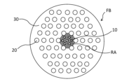
- FIG. 1 is a cross-sectional view illustrating the structure of an optical fiber according to an embodiment of the present disclosure.
- FIG. 2 is a cross-sectional view showing the structure of an optical fiber according to a modified example of the present disclosure.
- FIG. 3 is a schematic diagram showing the intensity distribution of pump light in an optical fiber that does not include holes.
- FIG. 4 is a schematic diagram illustrating the intensity distribution of excitation light in an optical fiber according to an embodiment of the present disclosure.
- FIG. 5 is a schematic diagram showing the intensity distribution of excitation light when the contribution of the photonic crystal structure is taken into account in an optical fiber according to an embodiment of the present disclosure.
- FIG. 6 is a schematic diagram illustrating a configuration of an optical amplifier according to an embodiment of the present disclosure.
- FIG. 1 is a cross-sectional view showing the structure of an optical fiber according to an embodiment of the present disclosure.
- Fig. 2 is a cross-sectional view showing the structure of an optical fiber according to a modified example of the present disclosure.
- Figs. 1 and 2 show cross-sectional views of a cross section perpendicular to the extending direction (direction of the central axis) of the optical fiber FB.
- the optical fiber FB includes a core region 10, holes 20, and a cladding region 30.
- the core region 10 is doped with rare earth ions.
- rare earth ions that may be doped into the core region 10 of the optical fiber FB include, but are not limited to, Er 3+ , Pr 3+ , Tm 3+ , Yb 3+ , Nd 3+ , and Dy 3+ .
- the rare earth ions are selected according to the band of the signal light to be amplified. Multiple types of rare earth ions may be doped.
- the number and arrangement of the core regions 10 in the optical fiber FB are not limited to the examples shown in Figs. 1 and 2.
- the optical fiber FB may have any number of core regions 10.
- the multiple core regions 10 may be arranged in a circular ring shape, or in a square or hexagonal close-packed arrangement.
- the air holes 20 have a central axis parallel to the central axis of the core region 10 and are arranged to surround the core region 10.
- a plurality of air holes 20 are arranged in the optical fiber FB.
- a photonic crystal structure can be obtained by regularly arranging the air holes 20 in the cladding region 30.
- FIG. 1 shows a 54-hole structure as the photonic crystal structure, in which seven holes near the center of a row of hexagonally close-packed holes 20 are missing.
- FIG. 2 shows a 54-hole structure as the photonic crystal structure, in which one hole near the center of a row of hexagonally close-packed holes 20 is missing.
- the photonic crystal structure is not limited to the examples given here, and may be a hexagonally close-packed or square arrangement.
- an excitation light guide region RA is formed near the core region 10.
- the excitation light guide region RA is a part of the cladding region 30, and is a region surrounded by the air holes 20.
- the photonic crystal structure limits the mode of the excitation light propagating in the excitation light guide region RA.
- rare earth ions can be excited in all of the core regions 10 arranged in the excitation light guide region RA.
- the pumping light can be concentrated in the pumping light guide region RA so that the pumping light contributes to the amplification of the signal light propagating through the core region 10.
- the pumping light that does not overlap the core region 10 can be reduced, and the pumping efficiency by the optical fiber FB can be improved.
- the diameter of each air hole 20 may be 2 ⁇ m or more. This is because if the diameter of the air hole 20 were shorter than the wavelength of the light passing through the optical fiber FB, the air hole 20 itself would scatter the light passing through the optical fiber FB, increasing the scattering loss. Furthermore, the diameter of the air hole 20 is set to 2 ⁇ m or more in consideration of the controllability of the air hole 20 when forming the optical fiber FB by performing the drawing process (drawing) in which the base material is heated and stretched.
- the refractive index of the holes 20 may be lower than the refractive index of the cladding region 30. This prevents a decrease in the coupling efficiency (optical amplification efficiency) between the excitation light and the signal light.
- the cladding region 30 is arranged so as to include the core region 10 and the multiple holes 20 therein, and has a lower refractive index than the core region 10.
- the core region 10 and the above-mentioned excitation light guide region RA are arranged near the center of the cladding region 30.
- Fig. 3 is a schematic diagram showing the intensity distribution of pump light in an optical fiber without holes.
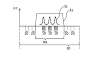
- Fig. 4 is a schematic diagram showing the intensity distribution of pump light in an optical fiber according to an embodiment of the present disclosure.
- the intensity distribution of the excitation light EL is shown on a straight line along the radial direction of the optical fiber FB.
- the intensity distribution of the signal light SL is also shown.
- the pumping light EL spreads throughout the cladding region 30, resulting in pumping light EL that does not overlap with the core region.
- the pumping light EL that does not overlap with the core region does not contribute to the amplification of the signal light SL propagating through the core region, resulting in reduced pumping efficiency.
- the pumping light EL is concentrated in the pumping light guide region RA. Therefore, the pumping light EL that does not overlap with the core region 10 is reduced. As a result, the pumping light EL contributes to the amplification of the signal light SL propagating through the core region 10, and the pumping efficiency by the optical fiber FB is improved.
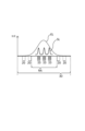
- FIG. 5 is a schematic diagram showing the intensity distribution of the excitation light EL when the contribution of the photonic crystal structure is taken into account in an optical fiber according to an embodiment of the present disclosure.
- the photonic crystal structure limits the number of modes of the excitation light EL, making it possible to increase the intensity of the excitation light EL in the core region.
- the pump light EL propagates in the fundamental mode, but the number of modes of the pump light EL may be two or more, i.e., a multimode state.
- the signal light SL is coupled between the cores.
- the gain deviation between the cores caused by the non-uniform intensity distribution of the pump light EL can be averaged.
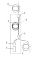
- FIG. 6 is a schematic diagram showing the configuration of an optical amplifier according to an embodiment of the present disclosure.
- the optical amplifier AP includes a pumping light source LD, an isolator TS1, an optical coupler PC, the optical fiber FB described in the above embodiment, and an isolator TS2.
- the excitation light source LD emits excitation light.
- the excitation light is light that excites the rare earth ions added to the optical fiber FB.
- the isolator TS1 introduces the excitation light from the excitation light source LD to the optical coupler PC.
- the isolator TS1 blocks the light traveling from the optical coupler PC to the excitation light source LD.
- the optical coupler PC introduces the signal light and the pumping light into one end of the optical fiber FB.
- the optical coupler PC introduces the signal light into the core region 10 of the optical fiber FB, and introduces the pumping light into the pumping light guide region RA of the cladding region 30, which is surrounded by holes 20.
- the optical coupler PC may be provided with a position adjustment mechanism (not shown) that adjusts the position at which the excitation light is introduced into the excitation light guide region RA.
- the position adjustment mechanism may control the position in the cross section of the excitation light guide region RA where the excitation light is coupled, and excite a predetermined number of modes of the excitation light.
- the signal light input to one end of the optical fiber FB together with the pump light is amplified while traveling through the optical fiber FB and is output from the other end of the optical fiber FB.
- the isolator TS2 (optical splitter) splits the signal light from the light output from the other end of the optical fiber FB.
- the split signal light is introduced into the output optical fiber B2.
- the isolator TS2 blocks the pump light traveling from the optical fiber FB to the output optical fiber B2.
- the optical fiber according to this embodiment comprises a core region doped with rare earth ions, a plurality of holes having a central axis parallel to the central axis of the core region and arranged so as to surround the core region, and a cladding region arranged so as to contain the core region and the plurality of holes therein, and having a refractive index lower than that of the core region.
- the optical fiber according to this embodiment may have a photonic crystal structure in which a plurality of holes are regularly arranged in a cross section perpendicular to the central axis of the core region.
- the photonic crystal structure limits the mode of the excitation light propagating in the excitation light waveguide region. In particular, since the excitation light propagates in a limited mode in the excitation light waveguide region, rare earth ions can be excited in all of the core regions arranged in the excitation light waveguide region.
- the pump light can be concentrated in the pump light guide region so that the pump light contributes to the amplification of the signal light propagating through the core region. As a result, the amount of pump light that does not overlap the core region can be reduced, improving the pumping efficiency of the optical fiber.
- the optical fiber according to this embodiment may have a plurality of holes arranged in a square or hexagonal close-packed arrangement in a cross section perpendicular to the central axis of the core region. This makes it possible to effectively concentrate the excitation light in the excitation light guide region. As a result, the excitation light that does not overlap the core region can be reduced, and the excitation efficiency of the optical fiber can be improved.
- the diameter of each air hole may be 2 ⁇ m or more. This suppresses the air holes themselves from scattering the light passing through the optical fiber, and prevents the installation of air holes from increasing scattering loss. Furthermore, the controllability of the air holes can be maintained during the elongation process in which the base material is heated and elongated.
- the refractive index of the air holes may be lower than the refractive index of the cladding region. This prevents a decrease in the coupling efficiency (optical amplification efficiency) with the signal light in the optical fiber having air holes.
- the optical amplifier according to this embodiment includes the optical fiber described above, an excitation light source that emits excitation light that excites rare earth ions, an optical coupler that introduces signal light and excitation light into one end of the optical fiber, and an optical splitter that splits the signal light from the light output from the other end of the optical fiber. This makes it possible to amplify with high efficiency the signal light input to one end of the optical fiber together with the excitation light.
- the optical coupler may introduce the signal light into the core region and introduce the pump light into a pump light guide region in the cladding region that is surrounded by holes. This makes it possible to increase the intensity of the pump light in the core region. Furthermore, the position in the cross section of the pump light guide region where the pump light is coupled can be controlled, making it possible to excite a predetermined number of modes of the pump light. Furthermore, it is possible to average out the gain deviation between cores caused by the non-uniform intensity distribution of the pump light.
Landscapes
- Physics & Mathematics (AREA)
- Electromagnetism (AREA)
- Optics & Photonics (AREA)
- Engineering & Computer Science (AREA)
- Plasma & Fusion (AREA)
- General Physics & Mathematics (AREA)
- Lasers (AREA)
Abstract
Description
図1は、本開示の実施形態に係る光ファイバの構造を示す断面図である。図2は、本開示の変形例に係る光ファイバの構造を示す断面図である。図1,2では、光ファイバFBの延在する方向(中心軸の方向)に直交する断面での断面図が示されている。光ファイバFBは、コア領域10と、空孔20と、クラッド領域30と、を備える。
次に、クラッド領域30における空孔20の配置の有無に起因する励起光の分布の変化を説明する。図3は、空孔を含まない場合における、光ファイバ内の励起光の強度分布を示す模式図である。図4は、本開示の実施形態に係る光ファイバ内の励起光の強度分布を示す模式図である。
次に、上述した実施形態で説明した光ファイバFBを用いた光増幅器APを説明する。図6は、本開示の実施形態に係る光増幅器の構成を示す模式図である。光増幅器APは、励起光源LDと、アイソレータTS1と、光結合器PCと、上述した実施形態で説明した光ファイバFBと、アイソレータTS2と、を備える。
以上詳細に説明したように、本実施形態に係る光ファイバは、希土類イオンを添加したコア領域と、コア領域の中心軸に対して平行な中心軸を有し、コア領域を囲むように配置された複数の空孔と、コア領域及び複数の空孔を内部に含むように配置され、コア領域よりも低い屈折率を有するクラッド領域と、を備える。
20 空孔
30 クラッド領域
RA 励起光導波領域
AP 光増幅器
B1 入力側光ファイバ
B2 出力側光ファイバ
FB 光ファイバ
LD 励起光源
PC 光結合器
TS1,TS2 アイソレータ(光分波器)
Claims (7)
- 希土類イオンを添加したコア領域と、
前記コア領域の中心軸に対して平行な中心軸を有し、前記コア領域を囲むように配置された複数の空孔と、
前記コア領域及び複数の前記空孔を内部に含むように配置され、前記コア領域よりも低い屈折率を有するクラッド領域と、
を備える光ファイバ。 - 前記コア領域の中心軸に垂直な断面において、複数の前記空孔は、規則的に配置されてフォトニッククリスタル構造を形成している、請求項1に記載の光ファイバ。
- 前記断面において、複数の前記空孔は、正方配置又は六方最密配置されている、請求項2に記載の光ファイバ。
- 1つの前記空孔の直径は2μm以上である、請求項1に記載の光ファイバ。
- 前記空孔の屈折率は前記クラッド領域の屈折率よりも低い、請求項1に記載の光ファイバ。
- 請求項1~5のいずれか一項に記載の光ファイバと、
前記希土類イオンを励起させる励起光を出射する励起光源と、
信号光及び前記励起光を前記光ファイバの一端に導入する光結合器と、
前記光ファイバの他端から出力される光から前記信号光を分波する光分波器と、
を備える光増幅器。 - 前記光結合器は、
前記信号光を前記コア領域に導入し、
前記励起光を、前記クラッド領域のうち、前記空孔によって囲まれた励起光導波領域に導入する、請求項6に記載の光増幅器。
Priority Applications (2)
| Application Number | Priority Date | Filing Date | Title |
|---|---|---|---|
| JP2025509281A JPWO2024201650A1 (ja) | 2023-03-27 | 2023-03-27 | |
| PCT/JP2023/012185 WO2024201650A1 (ja) | 2023-03-27 | 2023-03-27 | 光ファイバ及び光増幅器 |
Applications Claiming Priority (1)
| Application Number | Priority Date | Filing Date | Title |
|---|---|---|---|
| PCT/JP2023/012185 WO2024201650A1 (ja) | 2023-03-27 | 2023-03-27 | 光ファイバ及び光増幅器 |
Publications (1)
| Publication Number | Publication Date |
|---|---|
| WO2024201650A1 true WO2024201650A1 (ja) | 2024-10-03 |
Family
ID=92904038
Family Applications (1)
| Application Number | Title | Priority Date | Filing Date |
|---|---|---|---|
| PCT/JP2023/012185 Ceased WO2024201650A1 (ja) | 2023-03-27 | 2023-03-27 | 光ファイバ及び光増幅器 |
Country Status (2)
| Country | Link |
|---|---|
| JP (1) | JPWO2024201650A1 (ja) |
| WO (1) | WO2024201650A1 (ja) |
Citations (14)
| Publication number | Priority date | Publication date | Assignee | Title |
|---|---|---|---|---|
| JP2004077891A (ja) * | 2002-08-20 | 2004-03-11 | Mitsubishi Cable Ind Ltd | フォトニッククリスタルファイバ及びその設計方法 |
| JP2005500583A (ja) * | 2001-08-30 | 2005-01-06 | クリスタル ファイバー アクティーゼルスカブ | 高開口数の光ファイバー、その製造方法並びにその使用法 |
| WO2005017582A1 (ja) * | 2003-08-13 | 2005-02-24 | Nippon Telegraph And Telephone Corporation | 光ファイバおよびその製造方法 |
| US7340140B1 (en) * | 2005-06-07 | 2008-03-04 | The Boeing Company | Er/Yb double clad photonic crystal fiber |
| JP2008130686A (ja) * | 2006-11-17 | 2008-06-05 | Rohm Co Ltd | ファイバーレーザ |
| JP2008141066A (ja) * | 2006-12-04 | 2008-06-19 | Hitachi Cable Ltd | ファイバレーザ装置用光ファイバ及びファイバレーザ装置 |
| JP2009060097A (ja) * | 2007-08-07 | 2009-03-19 | Hitachi Cable Ltd | ファイバレーザ用光ファイバ及びその製造方法、並びにファイバレーザ |
| WO2009107414A1 (ja) * | 2008-02-27 | 2009-09-03 | 古河電気工業株式会社 | 光伝送システムおよびマルチコア光ファイバ |
| JP2010517112A (ja) * | 2007-01-31 | 2010-05-20 | コーニング インコーポレイテッド | 大開口数ファイバ |
| WO2012172997A1 (ja) * | 2011-06-16 | 2012-12-20 | 古河電気工業株式会社 | マルチコア増幅光ファイバ |
| WO2013145142A1 (ja) * | 2012-03-27 | 2013-10-03 | 富士通株式会社 | 分散補償器 |
| WO2014141766A1 (ja) * | 2013-03-14 | 2014-09-18 | 株式会社フジクラ | フォトニックバンドギャップファイバ、及び、それを用いたファイバレーザ装置 |
| CN104215367A (zh) * | 2014-08-28 | 2014-12-17 | 天津大学 | 多维应力光子晶体光纤测试装置及方法 |
| KR20160130021A (ko) * | 2015-04-30 | 2016-11-10 | 한국광기술원 | 이중 클래딩형 광섬유 및 이를 적용한 광섬유 레이저 |
-
2023
- 2023-03-27 JP JP2025509281A patent/JPWO2024201650A1/ja active Pending
- 2023-03-27 WO PCT/JP2023/012185 patent/WO2024201650A1/ja not_active Ceased
Patent Citations (14)
| Publication number | Priority date | Publication date | Assignee | Title |
|---|---|---|---|---|
| JP2005500583A (ja) * | 2001-08-30 | 2005-01-06 | クリスタル ファイバー アクティーゼルスカブ | 高開口数の光ファイバー、その製造方法並びにその使用法 |
| JP2004077891A (ja) * | 2002-08-20 | 2004-03-11 | Mitsubishi Cable Ind Ltd | フォトニッククリスタルファイバ及びその設計方法 |
| WO2005017582A1 (ja) * | 2003-08-13 | 2005-02-24 | Nippon Telegraph And Telephone Corporation | 光ファイバおよびその製造方法 |
| US7340140B1 (en) * | 2005-06-07 | 2008-03-04 | The Boeing Company | Er/Yb double clad photonic crystal fiber |
| JP2008130686A (ja) * | 2006-11-17 | 2008-06-05 | Rohm Co Ltd | ファイバーレーザ |
| JP2008141066A (ja) * | 2006-12-04 | 2008-06-19 | Hitachi Cable Ltd | ファイバレーザ装置用光ファイバ及びファイバレーザ装置 |
| JP2010517112A (ja) * | 2007-01-31 | 2010-05-20 | コーニング インコーポレイテッド | 大開口数ファイバ |
| JP2009060097A (ja) * | 2007-08-07 | 2009-03-19 | Hitachi Cable Ltd | ファイバレーザ用光ファイバ及びその製造方法、並びにファイバレーザ |
| WO2009107414A1 (ja) * | 2008-02-27 | 2009-09-03 | 古河電気工業株式会社 | 光伝送システムおよびマルチコア光ファイバ |
| WO2012172997A1 (ja) * | 2011-06-16 | 2012-12-20 | 古河電気工業株式会社 | マルチコア増幅光ファイバ |
| WO2013145142A1 (ja) * | 2012-03-27 | 2013-10-03 | 富士通株式会社 | 分散補償器 |
| WO2014141766A1 (ja) * | 2013-03-14 | 2014-09-18 | 株式会社フジクラ | フォトニックバンドギャップファイバ、及び、それを用いたファイバレーザ装置 |
| CN104215367A (zh) * | 2014-08-28 | 2014-12-17 | 天津大学 | 多维应力光子晶体光纤测试装置及方法 |
| KR20160130021A (ko) * | 2015-04-30 | 2016-11-10 | 한국광기술원 | 이중 클래딩형 광섬유 및 이를 적용한 광섬유 레이저 |
Also Published As
| Publication number | Publication date |
|---|---|
| JPWO2024201650A1 (ja) | 2024-10-03 |
Similar Documents
| Publication | Publication Date | Title |
|---|---|---|
| JP6794310B2 (ja) | マルチコアエルビウムドープファイバアンプ | |
| US6990282B2 (en) | Photonic crystal fibers | |
| JP6097778B2 (ja) | マルチモード・ファイバ | |
| US8564877B2 (en) | Photonic bandgap fiber and fiber amplifier | |
| US6826335B1 (en) | Multi-fibre arrangements for high power fibre lasers and amplifiers | |
| US8947768B2 (en) | Master oscillator—power amplifier systems | |
| US8498044B2 (en) | Amplification optical fiber, and optical fiber amplifier and resonator using the same | |
| US7280730B2 (en) | Large core holey fibers | |
| US20080219299A1 (en) | Optical fibre laser | |
| US20050207455A1 (en) | Method and apparatus for efficient coupling of pump light into fiber amplifiers | |
| JP2014135508A (ja) | 伝送、および増幅用マルチコアファイバ、および増幅器コアにポンプ光を発射するための仕組み | |
| Abedin et al. | State-of-the-art multicore fiber amplifiers for space division multiplexing | |
| JP6294486B2 (ja) | 超高出力単一モードファイバーレーザーシステム | |
| EP2625753B1 (en) | High power neodymium fiber lasers and amplifiers | |
| US9716365B2 (en) | High power neodymium fiber lasers and amplifiers | |
| US9673589B2 (en) | Amplification optical fiber and optical fiber amplifier | |
| JP2009129989A (ja) | ファイバレーザ用光ファイバ及びその製造方法、並びにファイバレーザ | |
| CN110663146B (zh) | 大功率包层泵浦单模光纤拉曼激光器 | |
| WO2024195031A1 (ja) | 光ファイバ及び光増幅器 | |
| JP2014099453A (ja) | 増幅用マルチコア光ファイバおよびマルチコア光ファイバ増幅器 | |
| US20250105578A1 (en) | Optical fiber for amplification, optical amplifier, and method for controlling optical amplifier | |
| WO2013002787A1 (en) | High power raman-based fiber laser system and method of operating the same | |
| US20260045754A1 (en) | Optical fiber for amplification and cladding-pumped optical fiber amplifier | |
| Vakhrushev et al. | Double-Clad Bismuth-Doped Fiber with a Rectangular Inner Cladding for Laser Application. Photonics 2022, 9, 788 | |
| WO2026028430A1 (ja) | 光分岐デバイス及び光増幅器 |
Legal Events
| Date | Code | Title | Description |
|---|---|---|---|
| 121 | Ep: the epo has been informed by wipo that ep was designated in this application |
Ref document number: 23930290 Country of ref document: EP Kind code of ref document: A1 |
|
| ENP | Entry into the national phase |
Ref document number: 2025509281 Country of ref document: JP Kind code of ref document: A |
|
| WWE | Wipo information: entry into national phase |
Ref document number: 2025509281 Country of ref document: JP |
|
| NENP | Non-entry into the national phase |
Ref country code: DE |
|
| 122 | Ep: pct application non-entry in european phase |
Ref document number: 23930290 Country of ref document: EP Kind code of ref document: A1 |