WO2024201615A1 - 車両用駆動装置 - Google Patents
車両用駆動装置 Download PDFInfo
- Publication number
- WO2024201615A1 WO2024201615A1 PCT/JP2023/012021 JP2023012021W WO2024201615A1 WO 2024201615 A1 WO2024201615 A1 WO 2024201615A1 JP 2023012021 W JP2023012021 W JP 2023012021W WO 2024201615 A1 WO2024201615 A1 WO 2024201615A1
- Authority
- WO
- WIPO (PCT)
- Prior art keywords
- viscosity
- engine
- energy
- control system
- vehicle
- Prior art date
- Legal status (The legal status is an assumption and is not a legal conclusion. Google has not performed a legal analysis and makes no representation as to the accuracy of the status listed.)
- Ceased
Links
Images






Classifications
-
- F—MECHANICAL ENGINEERING; LIGHTING; HEATING; WEAPONS; BLASTING
- F02—COMBUSTION ENGINES; HOT-GAS OR COMBUSTION-PRODUCT ENGINE PLANTS
- F02N—STARTING OF COMBUSTION ENGINES; STARTING AIDS FOR SUCH ENGINES, NOT OTHERWISE PROVIDED FOR
- F02N11/00—Starting of engines by means of electric motors
- F02N11/08—Circuits specially adapted for starting of engines
-
- B—PERFORMING OPERATIONS; TRANSPORTING
- B60—VEHICLES IN GENERAL
- B60K—ARRANGEMENT OR MOUNTING OF PROPULSION UNITS OR OF TRANSMISSIONS IN VEHICLES; ARRANGEMENT OR MOUNTING OF PLURAL DIVERSE PRIME-MOVERS IN VEHICLES; AUXILIARY DRIVES FOR VEHICLES; INSTRUMENTATION OR DASHBOARDS FOR VEHICLES; ARRANGEMENTS IN CONNECTION WITH COOLING, AIR INTAKE, GAS EXHAUST OR FUEL SUPPLY OF PROPULSION UNITS IN VEHICLES
- B60K6/00—Arrangement or mounting of plural diverse prime-movers for mutual or common propulsion, e.g. hybrid propulsion systems comprising electric motors and internal combustion engines
- B60K6/20—Arrangement or mounting of plural diverse prime-movers for mutual or common propulsion, e.g. hybrid propulsion systems comprising electric motors and internal combustion engines the prime-movers consisting of electric motors and internal combustion engines, e.g. HEVs
- B60K6/42—Arrangement or mounting of plural diverse prime-movers for mutual or common propulsion, e.g. hybrid propulsion systems comprising electric motors and internal combustion engines the prime-movers consisting of electric motors and internal combustion engines, e.g. HEVs characterised by the architecture of the hybrid electric vehicle
- B60K6/46—Series type
-
- B—PERFORMING OPERATIONS; TRANSPORTING
- B60—VEHICLES IN GENERAL
- B60W—CONJOINT CONTROL OF VEHICLE SUB-UNITS OF DIFFERENT TYPE OR DIFFERENT FUNCTION; CONTROL SYSTEMS SPECIALLY ADAPTED FOR HYBRID VEHICLES; ROAD VEHICLE DRIVE CONTROL SYSTEMS FOR PURPOSES NOT RELATED TO THE CONTROL OF A PARTICULAR SUB-UNIT
- B60W10/00—Conjoint control of vehicle sub-units of different type or different function
- B60W10/04—Conjoint control of vehicle sub-units of different type or different function including control of propulsion units
- B60W10/06—Conjoint control of vehicle sub-units of different type or different function including control of propulsion units including control of combustion engines
-
- B—PERFORMING OPERATIONS; TRANSPORTING
- B60—VEHICLES IN GENERAL
- B60W—CONJOINT CONTROL OF VEHICLE SUB-UNITS OF DIFFERENT TYPE OR DIFFERENT FUNCTION; CONTROL SYSTEMS SPECIALLY ADAPTED FOR HYBRID VEHICLES; ROAD VEHICLE DRIVE CONTROL SYSTEMS FOR PURPOSES NOT RELATED TO THE CONTROL OF A PARTICULAR SUB-UNIT
- B60W10/00—Conjoint control of vehicle sub-units of different type or different function
- B60W10/30—Conjoint control of vehicle sub-units of different type or different function including control of auxiliary equipment, e.g. air-conditioning compressors or oil pumps
-
- B—PERFORMING OPERATIONS; TRANSPORTING
- B60—VEHICLES IN GENERAL
- B60W—CONJOINT CONTROL OF VEHICLE SUB-UNITS OF DIFFERENT TYPE OR DIFFERENT FUNCTION; CONTROL SYSTEMS SPECIALLY ADAPTED FOR HYBRID VEHICLES; ROAD VEHICLE DRIVE CONTROL SYSTEMS FOR PURPOSES NOT RELATED TO THE CONTROL OF A PARTICULAR SUB-UNIT
- B60W30/00—Purposes of road vehicle drive control systems not related to the control of a particular sub-unit, e.g. of systems using conjoint control of vehicle sub-units
- B60W30/18—Propelling the vehicle
- B60W30/192—Mitigating problems related to power-up or power-down of the driveline, e.g. start-up of a cold engine
- B60W30/194—Mitigating problems related to power-up or power-down of the driveline, e.g. start-up of a cold engine related to low temperature conditions, e.g. high viscosity of hydraulic fluid
-
- F—MECHANICAL ENGINEERING; LIGHTING; HEATING; WEAPONS; BLASTING
- F01—MACHINES OR ENGINES IN GENERAL; ENGINE PLANTS IN GENERAL; STEAM ENGINES
- F01M—LUBRICATING OF MACHINES OR ENGINES IN GENERAL; LUBRICATING INTERNAL COMBUSTION ENGINES; CRANKCASE VENTILATING
- F01M1/00—Pressure lubrication
- F01M1/02—Pressure lubrication using lubricating pumps
-
- F—MECHANICAL ENGINEERING; LIGHTING; HEATING; WEAPONS; BLASTING
- F01—MACHINES OR ENGINES IN GENERAL; ENGINE PLANTS IN GENERAL; STEAM ENGINES
- F01M—LUBRICATING OF MACHINES OR ENGINES IN GENERAL; LUBRICATING INTERNAL COMBUSTION ENGINES; CRANKCASE VENTILATING
- F01M5/00—Heating, cooling, or controlling temperature of lubricant; Lubrication means facilitating engine starting
-
- F—MECHANICAL ENGINEERING; LIGHTING; HEATING; WEAPONS; BLASTING
- F01—MACHINES OR ENGINES IN GENERAL; ENGINE PLANTS IN GENERAL; STEAM ENGINES
- F01M—LUBRICATING OF MACHINES OR ENGINES IN GENERAL; LUBRICATING INTERNAL COMBUSTION ENGINES; CRANKCASE VENTILATING
- F01M5/00—Heating, cooling, or controlling temperature of lubricant; Lubrication means facilitating engine starting
- F01M5/001—Heating
-
- F—MECHANICAL ENGINEERING; LIGHTING; HEATING; WEAPONS; BLASTING
- F02—COMBUSTION ENGINES; HOT-GAS OR COMBUSTION-PRODUCT ENGINE PLANTS
- F02D—CONTROLLING COMBUSTION ENGINES
- F02D29/00—Controlling engines, such controlling being peculiar to the devices driven thereby, the devices being other than parts or accessories essential to engine operation, e.g. controlling of engines by signals external thereto
- F02D29/02—Controlling engines, such controlling being peculiar to the devices driven thereby, the devices being other than parts or accessories essential to engine operation, e.g. controlling of engines by signals external thereto peculiar to engines driving vehicles; peculiar to engines driving variable pitch propellers
-
- B—PERFORMING OPERATIONS; TRANSPORTING
- B60—VEHICLES IN GENERAL
- B60K—ARRANGEMENT OR MOUNTING OF PROPULSION UNITS OR OF TRANSMISSIONS IN VEHICLES; ARRANGEMENT OR MOUNTING OF PLURAL DIVERSE PRIME-MOVERS IN VEHICLES; AUXILIARY DRIVES FOR VEHICLES; INSTRUMENTATION OR DASHBOARDS FOR VEHICLES; ARRANGEMENTS IN CONNECTION WITH COOLING, AIR INTAKE, GAS EXHAUST OR FUEL SUPPLY OF PROPULSION UNITS IN VEHICLES
- B60K6/00—Arrangement or mounting of plural diverse prime-movers for mutual or common propulsion, e.g. hybrid propulsion systems comprising electric motors and internal combustion engines
- B60K6/20—Arrangement or mounting of plural diverse prime-movers for mutual or common propulsion, e.g. hybrid propulsion systems comprising electric motors and internal combustion engines the prime-movers consisting of electric motors and internal combustion engines, e.g. HEVs
- B60K6/22—Arrangement or mounting of plural diverse prime-movers for mutual or common propulsion, e.g. hybrid propulsion systems comprising electric motors and internal combustion engines the prime-movers consisting of electric motors and internal combustion engines, e.g. HEVs characterised by apparatus, components or means specially adapted for HEVs
- B60K6/24—Arrangement or mounting of plural diverse prime-movers for mutual or common propulsion, e.g. hybrid propulsion systems comprising electric motors and internal combustion engines the prime-movers consisting of electric motors and internal combustion engines, e.g. HEVs characterised by apparatus, components or means specially adapted for HEVs characterised by the combustion engines
-
- B—PERFORMING OPERATIONS; TRANSPORTING
- B60—VEHICLES IN GENERAL
- B60W—CONJOINT CONTROL OF VEHICLE SUB-UNITS OF DIFFERENT TYPE OR DIFFERENT FUNCTION; CONTROL SYSTEMS SPECIALLY ADAPTED FOR HYBRID VEHICLES; ROAD VEHICLE DRIVE CONTROL SYSTEMS FOR PURPOSES NOT RELATED TO THE CONTROL OF A PARTICULAR SUB-UNIT
- B60W2510/00—Input parameters relating to a particular sub-units
- B60W2510/24—Energy storage means
- B60W2510/242—Energy storage means for electrical energy
- B60W2510/244—Charge state
-
- B—PERFORMING OPERATIONS; TRANSPORTING
- B60—VEHICLES IN GENERAL
- B60W—CONJOINT CONTROL OF VEHICLE SUB-UNITS OF DIFFERENT TYPE OR DIFFERENT FUNCTION; CONTROL SYSTEMS SPECIALLY ADAPTED FOR HYBRID VEHICLES; ROAD VEHICLE DRIVE CONTROL SYSTEMS FOR PURPOSES NOT RELATED TO THE CONTROL OF A PARTICULAR SUB-UNIT
- B60W2710/00—Output or target parameters relating to a particular sub-units
- B60W2710/30—Auxiliary equipments
-
- B—PERFORMING OPERATIONS; TRANSPORTING
- B60—VEHICLES IN GENERAL
- B60W—CONJOINT CONTROL OF VEHICLE SUB-UNITS OF DIFFERENT TYPE OR DIFFERENT FUNCTION; CONTROL SYSTEMS SPECIALLY ADAPTED FOR HYBRID VEHICLES; ROAD VEHICLE DRIVE CONTROL SYSTEMS FOR PURPOSES NOT RELATED TO THE CONTROL OF A PARTICULAR SUB-UNIT
- B60W2710/00—Output or target parameters relating to a particular sub-units
- B60W2710/30—Auxiliary equipments
- B60W2710/305—Auxiliary equipments target power to auxiliaries
-
- B—PERFORMING OPERATIONS; TRANSPORTING
- B60—VEHICLES IN GENERAL
- B60Y—INDEXING SCHEME RELATING TO ASPECTS CROSS-CUTTING VEHICLE TECHNOLOGY
- B60Y2200/00—Type of vehicle
- B60Y2200/90—Vehicles comprising electric prime movers
- B60Y2200/92—Hybrid vehicles
-
- B—PERFORMING OPERATIONS; TRANSPORTING
- B60—VEHICLES IN GENERAL
- B60Y—INDEXING SCHEME RELATING TO ASPECTS CROSS-CUTTING VEHICLE TECHNOLOGY
- B60Y2306/00—Other features of vehicle sub-units
- B60Y2306/03—Lubrication
-
- B—PERFORMING OPERATIONS; TRANSPORTING
- B60—VEHICLES IN GENERAL
- B60Y—INDEXING SCHEME RELATING TO ASPECTS CROSS-CUTTING VEHICLE TECHNOLOGY
- B60Y2400/00—Special features of vehicle units
- B60Y2400/43—Engines
-
- F—MECHANICAL ENGINEERING; LIGHTING; HEATING; WEAPONS; BLASTING
- F01—MACHINES OR ENGINES IN GENERAL; ENGINE PLANTS IN GENERAL; STEAM ENGINES
- F01M—LUBRICATING OF MACHINES OR ENGINES IN GENERAL; LUBRICATING INTERNAL COMBUSTION ENGINES; CRANKCASE VENTILATING
- F01M1/00—Pressure lubrication
- F01M1/02—Pressure lubrication using lubricating pumps
- F01M2001/0207—Pressure lubrication using lubricating pumps characterised by the type of pump
- F01M2001/0215—Electrical pumps
-
- F—MECHANICAL ENGINEERING; LIGHTING; HEATING; WEAPONS; BLASTING
- F01—MACHINES OR ENGINES IN GENERAL; ENGINE PLANTS IN GENERAL; STEAM ENGINES
- F01M—LUBRICATING OF MACHINES OR ENGINES IN GENERAL; LUBRICATING INTERNAL COMBUSTION ENGINES; CRANKCASE VENTILATING
- F01M5/00—Heating, cooling, or controlling temperature of lubricant; Lubrication means facilitating engine starting
- F01M2005/008—Lubrication means facilitating engine starting
-
- Y—GENERAL TAGGING OF NEW TECHNOLOGICAL DEVELOPMENTS; GENERAL TAGGING OF CROSS-SECTIONAL TECHNOLOGIES SPANNING OVER SEVERAL SECTIONS OF THE IPC; TECHNICAL SUBJECTS COVERED BY FORMER USPC CROSS-REFERENCE ART COLLECTIONS [XRACs] AND DIGESTS
- Y02—TECHNOLOGIES OR APPLICATIONS FOR MITIGATION OR ADAPTATION AGAINST CLIMATE CHANGE
- Y02T—CLIMATE CHANGE MITIGATION TECHNOLOGIES RELATED TO TRANSPORTATION
- Y02T10/00—Road transport of goods or passengers
- Y02T10/60—Other road transportation technologies with climate change mitigation effect
- Y02T10/62—Hybrid vehicles
Definitions
- This disclosure relates to a vehicle drive system.
- the engine oil By activating a heater installed in an oil pan or the like, the engine oil can be warmed and the oil viscosity can be reduced, improving the startability of the engine.
- the type and deterioration state of the engine oil injected into the engine varies from vehicle to vehicle, it is common for the viscosity change characteristics of the engine oil to also differ from vehicle to vehicle.
- simply activating a heater based on the oil temperature makes it difficult to appropriately reduce the oil viscosity, making it difficult to improve the startability of the engine.
- a vehicle drive device has an electric pump that pumps engine oil, an electric heater that warms the engine oil, and a starter motor that starts and rotates an output shaft.
- the vehicle drive device has a control system that controls the electric pump, the electric heater, and the starter motor.
- the control system drives the electric pump before starting the engine, and calculates a first actual viscosity of the engine oil based on the load torque of the electric pump.
- the control system provides a first energy to the electric heater to operate it, and after operating the electric heater, drives the electric pump before starting the engine, and calculates a second actual viscosity of the engine oil based on the load torque of the electric pump.
- the control system calculates a second energy to be provided to the electric heater based on the second actual viscosity and a target viscosity of the engine oil. After providing the second energy to operate the electric heater, the control system drives the starter motor to start and rotate the output shaft.
- This disclosure can have the effect of improving engine startability.
- FIG. 1 is a diagram illustrating an example of a vehicle including a vehicle drive device according to an embodiment.
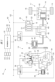
- FIG. 1 is a diagram illustrating an example of a vehicle drive device.
- FIG. 2 is a diagram illustrating an example of a basic structure of a control unit.
- FIG. 4 is a diagram showing an example of an execution status of a combustion power generation mode and a power generation stop mode. 4 is a flowchart showing an example of an execution procedure of oil heating control. 4 is a flowchart showing an example of an execution procedure of oil heating control.
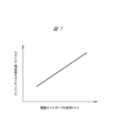
- FIG. 4 is a diagram illustrating an example of a relationship between a load torque of an electric oil pump and an actual viscosity of engine oil.
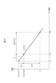
- FIG. 4 is a diagram showing an example of a relationship between temperature and viscosity of engine oil.
- FIG. 4 is a diagram showing an example of a relationship between temperature and viscosity of engine oil.
- FIG. 4 is a diagram showing an example of a relationship between temperature and viscosity of engine oil.
- FIG. 4 is a diagram showing an example of the relationship between oil viscosity and starting energy. 4 is a timing chart showing an example of an execution state of oil heating control.
- FIG. 11 is a diagram showing a vehicle drive device according to another embodiment.
- Fig. 1 is a diagram showing an example of a vehicle 11 equipped with a vehicle drive device 10 according to an embodiment.
- the vehicle drive device 10 has a power generation unit 14 including an engine 12 and a starter generator 13, and a drive unit 17 including an electric axle 16 connected to wheels 15.
- the power generation unit 14 and the drive unit 17 are connected to each other via a power supply unit 20 including an inverter 18 and a battery pack 19.
- the vehicle 11 shown in the figure is a so-called series-type hybrid vehicle, but is not limited thereto, and may be a series-parallel type hybrid vehicle.
- FIG. 2 is a diagram showing an example of a vehicle drive device 10.
- the engine 12 has a cylinder block 21 and a cylinder head 22 attached thereto.
- the engine 12 also has a crankshaft (output shaft) 23 rotatably supported by the cylinder block 21, and a piston 24 housed in the cylinder block 21 so that it can reciprocate.
- the crankshaft 23 and the piston 24 are connected to each other via a connecting rod 25.
- the cylinder head 22 has an injector 27 that injects fuel into the combustion chamber 26, and an ignition device 28 consisting of a spark plug or the like that ignites the air-fuel mixture in the combustion chamber 26.
- the engine 12 has an electric oil pump (electric pump) 30 that pumps engine oil.
- the electric oil pump 30 has a pump section 31 consisting of a gear pump, a motor section 32 that rotates and drives the pump section 31, and a drive circuit section 33 that controls the current supply state of the motor section 32.
- the engine oil X in the oil pan 34 is supplied from the oil passage of the cylinder block 21 to each sliding section such as a bearing.
- the engine oil supplied to each sliding section in the engine 12 is returned to the oil pan 34 at the bottom of the cylinder block after lubricating each sliding section.
- the oil pan 34 of the engine 12 is provided with an electric heater 35 that generates heat when current is applied.
- the electric oil pump 30, the electric heater 35, the injector 27, and the ignition device 28 are connected to an engine control unit 36, which is an electronic control unit.
- a starter generator (starter motor) 13 is connected to the crankshaft 23 of the engine 12 via a belt mechanism 40.
- the starter generator 13 has a stator 41 wound with a stator coil, and a rotor 42 rotatably housed within the stator 41.
- the starter generator 13 is a so-called ISG (Integrated Starter Generator) that functions as both a generator and an electric motor. In other words, the starter generator 13 not only functions as a generator that generates electricity using engine power, but also as an electric motor that starts and rotates the crankshaft 23 when the engine is started.
- a switching circuit section 43 consisting of multiple switching elements and the like is connected to the stator 41 of the starter generator 13.
- a battery pack 19 consisting of battery cells such as lithium-ion batteries is connected to the switching circuit section 43 of the inverter 18.
- the electric axle 16 has a driving motor 44 and a differential mechanism 45.
- the driving motor 44 has a stator 46 wound with a stator coil, and a rotor 47 rotatably housed in the stator 46.
- the rotor 47 of the driving motor 44 is connected to the wheels 15 via a gear train 48 and a differential mechanism 45.
- a switching circuit unit 49 consisting of multiple switching elements and the like is connected to the stator 46 of the driving motor 44.
- the battery pack 19 is connected to the switching circuit unit 49 of the inverter 18.
- a motor control unit 50 which is an electronic control unit, is connected to the inverter 18.
- the battery pack 19 has a number of battery modules 51 consisting of a number of battery cells, and a battery control unit 52 that monitors the charging and discharging of the battery modules 51.
- the battery pack 19 also has a battery sensor 53 that detects the charging and discharging current and the terminal voltage, etc.
- the battery control unit 52 which is an electronic control unit, calculates the SOC (State of Charge), which is the state of charge of the battery pack 19, based on the charging and discharging current and the terminal voltage, etc.
- the SOC of the battery pack 19 is a ratio that indicates the remaining amount of electricity stored in the battery pack 19, and is the ratio of the amount of stored electricity to the full charge capacity of the battery pack 19.
- the vehicle drive device 10 has a control system 60 consisting of a plurality of electronic control units.
- the electronic control units constituting the control system 60 include the engine control unit 36, the motor control unit 50, and the battery control unit 52 described above.
- Another electronic control unit constituting the control system 60 is a vehicle control unit 61 that outputs control signals to the control units 36, 50, and 52 described above.
- These control units 36, 50, 52, and 61 are connected to each other so as to be able to communicate with each other via an in-vehicle network 62 such as a Controller Area Network (CAN).
- CAN Controller Area Network
- the vehicle control unit 61 sets operation targets for the power generation unit 14, drive unit 17, etc. based on input information from various control units and various sensors described below. The vehicle control unit 61 then generates control signals according to the operation targets for the power generation unit 14, drive unit 17, etc., and outputs these control signals to the engine control unit 36, motor control unit 50, etc.
- Sensors connected to the vehicle control unit 61 include an accelerator sensor 63 that detects the amount of accelerator pedal operation, and a brake sensor 64 that detects the amount of brake pedal operation.
- Sensors connected to the vehicle control unit 61 include a vehicle speed sensor 65 that detects the vehicle speed, which is the traveling speed of the vehicle 11, and a temperature sensor 66 that detects the outside air temperature. Furthermore, a start switch 67 that is operated by the driver when the control system 60 is started is connected to the vehicle control unit 61.
- FIG. 3 is a diagram showing an example of the basic structure of the control units 36, 50, 52, and 61.
- the control units 36, 50, 52, and 61 which are electronic control units, have a microcontroller 72 incorporating a processor 70 and a main memory (memory) 71, etc.
- a predetermined program is stored in the main memory 71, and the program is executed by the processor 70.
- the processor 70 and the main memory 71 are connected to each other so that they can communicate with each other. Note that multiple processors 70 may be incorporated in the microcontroller 72, and multiple main memories 71 may be incorporated in the microcontroller 72.
- the control units 36, 50, 52, and 61 also have an input circuit 73, a drive circuit 74, a communication circuit 75, an external memory 76, and a power supply circuit 77.
- the input circuit 73 converts signals input from various sensors into signals that can be input to the microcontroller 72.
- the drive circuit 74 generates drive signals for various devices such as the inverter 18, the electric oil pump 30, and the electric heater 35, based on signals output from the microcontroller 72.
- the communication circuit 75 converts signals output from the microcontroller 72 into communication signals directed to other control units.
- the communication circuit 75 also converts communication signals received from other control units into signals that can be input to the microcontroller 72.
- the power supply circuit 77 supplies a stable power supply voltage to the microcontroller 72, the input circuit 73, the drive circuit 74, the communication circuit 75, the external memory 76, and the like.
- the external memory 76 which is a non-volatile memory, stores programs and various data.
- the vehicle drive device 10 has, as control modes for the power generation unit 14, a combustion power generation mode in which the starter generator 13 generates power, and a power generation stop mode in which the power generation of the starter generator 13 is stopped.
- the combustion power generation mode is a control mode in which the engine 12 is controlled to an operating state and the starter generator 13 is controlled to a power generating state.
- the power generation stop mode is a control mode in which the engine 12 and the starter generator 13 are controlled to a stopped state.
- FIG. 4 is a diagram showing an example of the execution status of the combustion power generation mode and the power generation stop mode.
- the control system 60 switches the control mode from the power generation stop mode to the combustion power generation mode.
- the control system 60 determines that the engine start condition for starting the engine 12 is met, and drives the starter generator 13 to start the engine 12.
- the control system 60 controls the starter generator 13 to a power generation state, and switches the control mode to the combustion power generation mode. This allows the starter generator 13 to generate electricity to charge the battery pack 19, and the SOC of the battery pack 19 can be gradually increased.
- the control system 60 switches the control mode from the combustion power generation mode to the power generation stop mode.
- a threshold S2 which is greater than threshold S1
- the control system 60 determines that an engine stop condition for stopping the engine 12 has been met, stops the engine 12, and switches the control mode to the power generation stop mode. This makes it possible to drive the traction motor 44 using the power stored in the battery pack 19, and allows the vehicle 11 to run with the engine 12 stopped. Note that even in the power generation stop mode, the traction motor 44 is controlled to a regenerative state when the vehicle decelerates, so the battery pack 19 is charged by the traction motor 44.
- ⁇ Oil heating control Flow chart>
- the control system 60 starts the engine 12 and controls the starter generator 13 to generate electricity.
- a low-temperature environment e.g., ⁇ 20° C.
- the viscosity of the engine oil hereinafter referred to as oil viscosity
- the control system 60 executes oil heating control to operate the electric heater 35 before starting the engine to warm the engine oil, thereby reducing the oil viscosity and improving the startability of the engine 12.
- Figures 5 and 6 are flowcharts showing an example of the procedure for executing oil heating control.
- the flowcharts shown in Figures 5 and 6 are connected to each other at point A and to each other at point B.
- each step of the oil heating control shown in Figures 5 and 6 is a step executed by the processor 70 that constitutes the control system 60.
- step S10 determines whether or not startup of the control system 60 has been completed. If the control system 60 determines in step S10 that system startup has been completed, it proceeds to step S11, where it determines whether or not the outside air temperature is below a predetermined threshold A1 (e.g., 0°C). If the control system 60 determines in step S11 that the outside air temperature is below threshold A1, it proceeds to step S12, where it temporarily drives the electric oil pump 30 before starting the engine. Then, in step S12, the control system 60 calculates an actual viscosity (first actual viscosity) Vx1, which is the actual oil viscosity, based on the load torque of the electric oil pump 30.
- first actual viscosity Vx1
- Figure 7 is a diagram showing an example of the relationship between the load torque of the electric oil pump 30 and the actual viscosity of the engine oil.
- the actual viscosity Vx1 of the engine oil increases as the load torque of the electric oil pump 30 increases. That is, in step S12 described above, the control system 60 calculates the actual viscosity Vx1 of the engine oil to be higher as the load torque of the electric oil pump 30 increases.
- the control system 60 is capable of calculating the load torque of the electric oil pump 30 based on the current consumption of the electric oil pump 30. That is, the control system 60 calculates the load torque of the electric oil pump 30 to be higher as the current consumption of the electric oil pump 30 driven at a constant rotational speed increases.
- step S13 the control system 60 operates the electric heater 35 by providing a predetermined pre-heating energy (first energy) E1 [kWh].
- step S14 the control system 60 again temporarily drives the electric oil pump 30 before starting the engine.
- step S14 the control system 60 calculates an actual viscosity (second actual viscosity) Vx2, which is the actual oil viscosity, based on the load torque of the electric oil pump 30. Note that, as shown in FIG. 7, even in step S14, the control system 60 calculates the actual viscosity Vx2 of the engine oil to be higher as the load torque of the electric oil pump 30 increases.
- the control system 60 proceeds to step S15 and calculates the main heating energy (second energy) Ex2 [kWh] to be applied to the electric heater 35.
- the main heating energy Ex2 is the energy required to reduce the oil viscosity from the actual viscosity Vx2 to the target viscosity Vt, and is the amount of power, i.e., energy, consumed by the electric heater 35.
- the target viscosity Vt of the engine oil is the upper limit of the oil viscosity required at engine start from the viewpoint of properly starting the engine 12 using the starter generator 13. In other words, by reducing the oil viscosity to the target viscosity Vt, the crankshaft 23 can be properly started and rotated by the starter generator 13, and the engine 12 can be properly started.
- FIG. 8 and Fig. 10 are diagrams showing an example of the relationship between engine oil temperature and viscosity.
- the viscosity change characteristic of engine oil OA is shown by a solid line
- the viscosity change characteristic of engine oil OB which is separate from engine oil OA
- a dashed line is shown in Fig. 8 and Fig. 9
- actual viscosity Va1 is the actual viscosity Vx1 of engine oil OA calculated in step S12
- actual viscosity Va2 is the actual viscosity Vx2 of engine oil OA calculated in step S15.
- actual viscosity Vb1 is the actual viscosity Vx1 of engine oil OB calculated in step S12
- actual viscosity Vb1 is the actual viscosity Vx2 of engine oil OB calculated in step S15.
- the main heating energy Ea2 from the pre-heating energy E1, the slope of the characteristic line La, and the amount of change (difference) Da2, and to supply this main heating energy Ea2 to the electric heater 35.
- the control system 60 calculates a larger main heating energy Ea2 as the change amount Da2 increases.
- the main heating energy Eb2 from the pre-heating energy E1, the slope of the characteristic line Lb, and the change amount (difference) Db2, and to supply this main heating energy Eb2 to the electric heater 35.
- the control system 60 calculates a larger main heating energy Eb2 as the amount of change Db2 increases.
- step S16 calculates the start-up energy Est1 [kWh] when the oil viscosity is the target viscosity Vt.
- This start-up energy (first start-up energy) Est1 is the energy consumed by the starter generator 13 when the engine is started when the oil viscosity is the target viscosity Vt.
- step S17 calculates the start-up energy Est2 [kWh] when the oil viscosity is the actual viscosity Vx2.
- This start-up energy (second start-up energy) Est2 is the energy consumed by the starter generator 13 when the engine is started when the oil viscosity is the actual viscosity Vx2.
- FIG. 11 is a diagram showing an example of the relationship between oil viscosity and starting energy.
- the starting energies Est1 and Est2 increase as the oil viscosity increases. That is, in step S16, the control system 60 calculates a larger starting energy Est1 the higher the target viscosity Vt. Also, in step S17, the control system 60 calculates a larger starting energy Est2 the higher the actual viscosity Vx2.
- the target viscosity Vt of the engine oil is a fixed value set in advance by simulation or the like, but may be changed in response to deterioration over time of the starter generator 13, etc.
- step S18 determines whether the sum of the start-up energy Est1 and the main heating energy Ex2 is below the start-up energy Est2.
- step S18 a situation in which the sum of the start-up energy Est1 and the main heating energy Ex2 is below the start-up energy Est2 means that operating the electric heater 35 before starting the engine consumes less energy when starting the engine.
- step S18 a situation in which the sum of the start-up energy Est1 and the main heating energy Ex2 exceeds the start-up energy Est2 means that not operating the electric heater 35 before starting the engine consumes less energy when starting the engine.
- step S18 determines whether the sum of the starting energy Est1 and the main heating energy Ex2 falls below the starting energy Est2.
- the process proceeds to step S19, where it determines whether the SOC of the battery pack 19 falls below the threshold value S1a.
- the threshold value S1a is set slightly higher than the threshold value S1, and a situation in which the SOC falls below the threshold value S1a indicates that a transition to the combustion power generation mode is imminent.
- step S20 the main heating energy Ex2 is used to operate the electric heater 35.
- step S21 the control system 60 calculates the actual viscosity Vx3, which is the actual oil viscosity, based on the load torque of the electric oil pump 30.
- step S22 determines whether the actual viscosity Vx3 is equal to or less than the target viscosity Vt.
- step S22 When the control system 60 determines in step S22 that the actual viscosity Vx3 exceeds the target viscosity Vt, it proceeds to step S23, as the engine oil is not sufficiently warmed, and adds a predetermined amount of energy to operate the electric heater 35. Also, when the control system 60 operates the electric heater 35 in step S23, it proceeds to step S21 to calculate the actual viscosity Vx3 again, and proceeds to step S22 to determine whether the actual viscosity Vx3 is equal to or less than the target viscosity Vt. In other words, the electric heater 35 continues to heat the engine oil until the actual viscosity Vx3 falls below the target viscosity Vt.
- step S24 determines whether the SOC of the battery pack 19 is below the threshold value S1.
- a situation in which the SOC is below the threshold value S1 means that the engine 12 is started and the mode is switched to combustion power generation mode, that is, the engine start condition is met. If the control system 60 determines in step S24 that the SOC is below the threshold value S1, the process proceeds to step S25 to drive the electric oil pump 30 and to step S26 to drive the starter generator 13 in order to switch from the power generation stop mode to the combustion power generation mode.
- step S12 which corresponds to the first step, the control system 60 calculates the actual viscosity Vx1 of the engine oil based on the load torque of the electric oil pump 30.
- steps S13 and S14 which correspond to the second step, the control system 60 operates the electric heater 35 with the pre-heating energy E1, and then calculates the actual viscosity Vx2 of the engine oil based on the load torque of the electric oil pump 30.
- step S15 which corresponds to the third step, the control system 60 calculates the main heating energy Ex2 to be applied to the electric heater 35 based on the actual viscosity Vx2 of the engine oil and the target viscosity Vt.
- control system 60 operates the electric heater 35 with the main heating energy Ex2, and then drives the starter generator 13 to start the engine 12. This makes it possible to appropriately reduce the oil viscosity in preparation for engine start, and improve the startability of the engine 12.
- step S20, S25, and S26 which correspond to the fourth step, the control system 60 activates the electric heater 35 with the main heating energy Ex2, then drives the electric oil pump 30 and then drives the starter generator 13. That is, the electric oil pump 30 is driven to pump engine oil, and then the starter generator 13 is driven to start and rotate the crankshaft 23. This reduces the rotational resistance of the crankshaft 23, further improving the startability of the engine 12.
- step S18 when the control system 60 determines in step S18 that the sum of the start energy Est1 and the main heating energy Ex2 is equal to or greater than the start energy Est2, the control system 60 proceeds to step S24 without operating the electric heater 35 from the viewpoint of improving energy efficiency, and determines whether the SOC is below the threshold value S1. That is, when the sum of the start energy Est1 and the main heating energy Ex2 exceeds the start energy Est2, and the SOC is below the threshold value S1 and the engine start condition is satisfied, the control system 60 prohibits the execution of step S20, which corresponds to the fourth step. In this case, the control system 60 bypasses step S20 and proceeds to step S24, so that the starter generator 13 is driven to start the engine 12 without operating the electric heater 35. In this way, it is possible to appropriately determine whether to operate the electric heater 35 from the viewpoint of energy consumption, and it is possible to improve the energy efficiency of the vehicle 11.
- Fig. 12 is a timing chart showing an example of an execution state of the oil heating control.
- the control system 60 when the control system 60 is started at time t1, the actual viscosity Vx1 of the engine oil before warming is calculated at time t2, and the actual viscosity Vx2 of the engine oil after warming is calculated at time t3.
- the main heating energy Ex2 to be applied to the electric heater 35 is calculated as described above.
- the SOC of the battery pack 19 increases or decreases depending on the power running state or regeneration state of the traveling motor 44.
- Fig. 13 is a diagram showing a vehicle drive device 80 of another embodiment.
- the vehicle drive device 80 has a power generation unit 82 consisting of an engine 81 and a starter generator 13.
- the engine 81 of the power generation unit 82 is an engine equipped with a so-called dry sump type hydraulic system.
- the engine 81 has an oil tank 83 that stores engine oil X, a scavenge pump 84 located upstream of the oil tank 83, and an electric oil pump 30 located downstream of the oil tank 83.
- the engine 81 also has an electric heater 35 provided in the oil tank 83.
- the scavenge pump 84 By driving the scavenge pump 84, engine oil is supplied from the oil pan 34 to the oil tank 83. Also, by driving the electric oil pump 30, the engine oil X in the oil tank 83 is supplied from the oil passages in the cylinder block 21 to each sliding part such as the bearings. The engine oil supplied to each sliding part in the engine 81 is returned to the oil pan 34 at the bottom of the cylinder block after lubricating each sliding part. Also, the electric oil pump 30, the electric heater 35, the scavenge pump 84, the injector 27, and the ignition device 28 are connected to the engine control unit 36, which is an electronic control unit.
- step S12 which corresponds to the first step, the control system 60 calculates the actual viscosity Vx1 of the engine oil based on the load torque of the electric oil pump 30.
- steps S13 and S14 which correspond to the second step, the control system 60 operates the electric heater 35 with the pre-heating energy E1, and then calculates the actual viscosity Vx2 of the engine oil based on the load torque of the electric oil pump 30.
- step S15 which corresponds to the third step, the control system 60 calculates the main heating energy Ex2 to be applied to the electric heater 35 based on the actual viscosity Vx2 of the engine oil and the target viscosity Vt.
- steps S20 and S26 which correspond to the fourth step, the control system 60 operates the electric heater 35 with the main heating energy Ex2, and then drives the starter generator 13 to start the engine 81. This allows the oil viscosity to be appropriately reduced in preparation for engine start-up, improving the startability of the engine 81.
- control system 60 is configured by multiple control units 36, 50, 52, and 61, but this is not limited to this.
- the control system 60 may be configured by one control unit.
- an electric heater that generates heat using an electric heating wire may be used as the electric heater 35, or a PTC (Positive Temperature Coefficient) heater may be used.
- the power source for the electric heater 35 and the electric oil pump 30 is a low-voltage battery, but this is not limited to this, and power may be supplied to the electric heater 35 and the electric oil pump 30 from a high-voltage battery pack 19.
- the characteristic lines La, Lb are straight lines, but this is not limited thereto, and the characteristic lines La, Lb may be curved lines.
- the characteristic lines La, Lb representing the viscosity change characteristics are calculated based on two actual viscosities Vx1, Vx2, but this is not limited thereto, and the characteristic lines La, Lb representing the viscosity change characteristics may be calculated based on three or more actual viscosities.
- the pre-heating energy E1 supplied to the electric heater 35 before calculating the actual viscosity Vx2 of the engine oil may be a preset fixed value, or may be a value that changes depending on the outside air temperature or oil temperature, etc.
- the characteristic lines showing the relationship between the load torque and the actual viscosities Vx1, Vx2 are straight lines, but this is not limited thereto, and the characteristic lines showing the relationship between the load torque and the actual viscosities Vx1, Vx2 may be curved lines.
- the characteristic line showing the relationship between the oil viscosity and the starting energies Est1 and Est2 is a straight line, but this is not limited thereto, and the characteristic line showing the relationship between the oil viscosity and the starting energies Est1 and Est2 may be a curved line.
- step S11 if it is determined in step S11 that the outside air temperature is equal to or higher than threshold A1, the oil viscosity is already low and there is no need to operate the electric heater 35, so the process bypasses step S20 and proceeds to step S24.
- the control system 60 determines whether the oil viscosity is low based on the outside air temperature, but this is not limited to this, and for example, it may also determine whether the oil viscosity is already low based on the engine oil temperature.
- the electric heater 35 it is determined whether or not to operate the electric heater 35 based on the starting energies Est1 and Est2, but this is not limited to this. For example, in a situation where the outside air temperature or oil temperature is below a predetermined value, the electric heater 35 may be operated before the engine is started without determining the starting energies Est1 and Est2. Also, in the flowcharts shown in Figures 5 and 6, after the electric heater 35 is operated by the main heating energy Ex2, the actual viscosity Vx3 of the engine oil is determined again, but this is not limited to this. In other words, after the electric heater 35 is operated by the main heating energy Ex2, the starter generator 13 may be driven to start the engine if the engine start condition is met without determining the actual viscosity Vx3 of the engine oil again.
- the starter generator 13 which functions as an electric motor and a generator, is used as the starter motor, but this is not limited to the above.
- an electric motor equipped with a pinion that meshes with the ring gear of the flywheel may be used as the starter motor, or a motor generator that is directly connected to the crankshaft 23 may be used as the starter motor.
- a motor generator that is connected to the crankshaft 23 via a damper mechanism, clutch mechanism, planetary gear mechanism, or the like may be used as the starter motor.
- Vehicle drive device 11
- Vehicle 12 Engine 13
- Starter generator (starter motor) 15 Wheels 23 Crankshaft (output shaft)
- Electric oil pump (electric pump) 35
- Travel motor 60 Control system 70
- Processor 71
- Main memory (memory) 80
- Vehicle drive device 81
- Engine Vx 1 Actual viscosity (first actual viscosity)
- Vt Target viscosity E1 Preheating energy (first energy) Ex2, Ea2, Eb2 Main heating energy (second energy) Da2, Db2 Change (difference)
- Est1 starting energy first starting energy
- Est2 starting energy second starting energy
Landscapes
- Engineering & Computer Science (AREA)
- Mechanical Engineering (AREA)
- General Engineering & Computer Science (AREA)
- Chemical & Material Sciences (AREA)
- Combustion & Propulsion (AREA)
- Transportation (AREA)
- Automation & Control Theory (AREA)
- Lubrication Of Internal Combustion Engines (AREA)
Abstract
Description
<車両構成>
図1は一実施形態の車両用駆動装置10を備えた車両11の一例を示す図である。図1に示すように、車両用駆動装置10は、エンジン12およびスタータジェネレータ13からなる発電ユニット14と、車輪15に連結された電動アクスル16からなる駆動ユニット17と、を有している。発電ユニット14と駆動ユニット17とは、インバータ18およびバッテリパック19からなる電源ユニット20を介して互いに接続されている。なお、図示する車両11は、所謂シリーズ方式のハイブリッド車両であるが、これに限られることはなく、シリーズパラレル方式のハイブリッド車両であっても良い。
図2に示すように、車両用駆動装置10は、複数の電子制御ユニットからなる制御システム60を有している。制御システム60を構成する電子制御ユニットとして、前述したエンジン制御ユニット36、モータ制御ユニット50およびバッテリ制御ユニット52がある。また、制御システム60を構成する電子制御ユニットとして、前述した各制御ユニット36,50,52に制御信号を出力する車両制御ユニット61がある。これらの制御ユニット36,50,52,61は、CAN(Controller Area Network)等の車載ネットワーク62を介して互いに通信可能に接続されている。
車両用駆動装置10は、発電ユニット14の制御モードとして、スタータジェネレータ13を発電させる燃焼発電モードと、スタータジェネレータ13の発電を停止させる発電停止モードと、を有している。燃焼発電モードは、エンジン12を運転状態に制御するとともにスタータジェネレータ13を発電状態に制御する制御モードである。また、発電停止モードは、エンジン12およびスタータジェネレータ13を停止状態に制御する制御モードである。
前述したように、制御システム60は、バッテリパック19のSOCが閾値S1を下回る場合に、エンジン12を始動してスタータジェネレータ13を発電状態に制御する。ここで、寒冷地等の低温環境下(例えば、-20℃)においては、エンジンオイルの粘度(以下、オイル粘度と記載する。)が高くクランク軸23の回転抵抗が大きいことから、スタータジェネレータ13によってクランク軸23を始動回転させることが困難であった。そこで、制御システム60は、エンジン始動前に電気ヒータ35を作動させてエンジンオイルを暖めることにより、オイル粘度を低下させてエンジン12の始動性を向上させるオイル加熱制御を実行する。
前述したオイル加熱制御をタイミングチャートに沿って説明する。図12はオイル加熱制御の実行状況の一例を示すタイミングチャートである。図12に示すように、時刻t1において制御システム60が起動されると、時刻t2では暖める前のエンジンオイルの実粘度Vx1が算出され、時刻t3では暖めた後のエンジンオイルの実粘度Vx2が算出される。このように、エンジンオイルの実粘度Vx1,Vx2が算出されると、前述したように、電気ヒータ35に与えるメイン加熱エネルギーEx2が算出される。また、時刻t4において発電停止モードによる走行が開始されると、走行用モータ44の力行状態または回生状態に応じてバッテリパック19のSOCが増減する。
図2に示した例では、エンジン12のオイルパン34に電気ヒータ35を設けているが、これに限られることはなく、エンジン12の他の箇所に電気ヒータ35を設けても良い。図13は他の実施形態の車両用駆動装置80を示す図である。
11 車両
12 エンジン
13 スタータジェネレータ(スタータモータ)
15 車輪
23 クランク軸(出力軸)
30 電動オイルポンプ(電動ポンプ)
35 電気ヒータ
44 走行用モータ
60 制御システム
70 プロセッサ
71 メインメモリ(メモリ)
80 車両用駆動装置
81 エンジン
Vx1 実粘度(第1実粘度)
Vx2 実粘度(第2実粘度)
Vt 目標粘度
E1 プレ加熱エネルギー(第1エネルギー)
Ex2,Ea2,Eb2 メイン加熱エネルギー(第2エネルギー)
Da2,Db2 変化量(差分)
Est1 始動エネルギー(第1始動エネルギー)
Est2 始動エネルギー(第2始動エネルギー)
Claims (10)
- エンジンを備える車両用駆動装置であって、
前記エンジンに設けられ、エンジンオイルを圧送する電動ポンプと、
前記エンジンに設けられ、前記エンジンオイルを暖める電気ヒータと、
前記エンジンに設けられ、出力軸を始動回転させるスタータモータと、
互いに通信可能に接続されるプロセッサおよびメモリを備え、前記電動ポンプ、前記電気ヒータおよび前記スタータモータを制御する制御システムと、
を有し、
前記制御システムは、
エンジン始動前に前記電動ポンプを駆動し、前記電動ポンプの負荷トルクに基づいて前記エンジンオイルの第1実粘度を算出する第1ステップと、
前記電気ヒータに第1エネルギーを与えて作動させ、前記電気ヒータを作動させてからエンジン始動前に前記電動ポンプを駆動し、前記電動ポンプの負荷トルクに基づいて前記エンジンオイルの第2実粘度を算出する第2ステップと、
前記エンジンオイルの前記第2実粘度と目標粘度とに基づいて、前記電気ヒータに与える第2エネルギーを算出する第3ステップと、
前記第2エネルギーを与えて前記電気ヒータに作動させた後に、前記スタータモータを駆動して前記出力軸を始動回転させる第4ステップと、
を実行する、
車両用駆動装置。 - 請求項1に記載の車両用駆動装置において、
前記制御システムは、前記第4ステップにおいて、
前記第2エネルギーを与えて前記電気ヒータを作動させた後に、前記電動ポンプを駆動してから前記スタータモータを駆動して前記出力軸を始動回転させる、
車両用駆動装置。 - 請求項1に記載の車両用駆動装置において、
前記制御システムは、前記第1ステップにおいて、
前記電動ポンプの負荷トルクが大きくなるほどに、前記第1実粘度を高く算出する、
車両用駆動装置。 - 請求項1に記載の車両用駆動装置において、
前記制御システムは、前記第2ステップにおいて、
前記電動ポンプの負荷トルクが大きくなるほどに、前記第2実粘度を高く算出する、
車両用駆動装置。 - 請求項1に記載の車両用駆動装置において、
前記制御システムは、前記第3ステップにおいて、
前記第2実粘度と前記目標粘度との差分が大きくなるほどに、前記第2エネルギーを大きく算出する、
車両用駆動装置。 - 請求項1に記載の車両用駆動装置において、
前記制御システムは、前記第3ステップにおいて、
前記第1実粘度、前記第2実粘度および前記第1エネルギーに基づいて、前記エンジンオイルの粘度変化特性を算出し、
前記粘度変化特性、前記第2実粘度および前記目標粘度に基づいて、前記第2エネルギーを算出する、
車両用駆動装置。 - 請求項1に記載の車両用駆動装置において、
前記制御システムは、
前記エンジンオイルの粘度が前記目標粘度である場合に前記スタータモータによって消費される第1始動エネルギーを算出し、
前記エンジンオイルの粘度が前記第2実粘度である場合に前記スタータモータによって消費される第2始動エネルギーを算出し、
前記第1始動エネルギーと前記第2エネルギーとの合計値が前記第2始動エネルギーを下回る状況のもとで、エンジン始動条件が成立した場合に、前記第4ステップを実行する、
車両用駆動装置。 - 請求項7に記載の車両用駆動装置において、
前記制御システムは、
前記第1始動エネルギーと前記第2エネルギーとの合計値が前記第2始動エネルギーを上回る状況のもとで、エンジン始動条件が成立した場合に、
前記第4ステップの実行を禁止し、前記電気ヒータを作動させずに前記スタータモータを駆動して前記出力軸を始動回転させる、
車両用駆動装置。 - 請求項7に記載の車両用駆動装置において、
前記制御システムは、前記目標粘度が高くなるほどに、前記第1始動エネルギーを大きく算出し、
前記制御システムは、前記第2実粘度が高くなるほどに、前記第2始動エネルギーを大きく算出する、
車両用駆動装置。 - 請求項1に記載の車両用駆動装置において、
車輪に連結される走行用モータを有する、
車両用駆動装置。
Priority Applications (4)
| Application Number | Priority Date | Filing Date | Title |
|---|---|---|---|
| JP2024550849A JP7737567B2 (ja) | 2023-03-24 | 2023-03-24 | 車両用駆動装置 |
| CN202380014225.XA CN119032219A (zh) | 2023-03-24 | 2023-03-24 | 车辆用驱动装置 |
| PCT/JP2023/012021 WO2024201615A1 (ja) | 2023-03-24 | 2023-03-24 | 車両用駆動装置 |
| US18/765,492 US12404828B2 (en) | 2023-03-24 | 2024-07-08 | Vehicle driving device |
Applications Claiming Priority (1)
| Application Number | Priority Date | Filing Date | Title |
|---|---|---|---|
| PCT/JP2023/012021 WO2024201615A1 (ja) | 2023-03-24 | 2023-03-24 | 車両用駆動装置 |
Related Child Applications (1)
| Application Number | Title | Priority Date | Filing Date |
|---|---|---|---|
| US18/765,492 Continuation US12404828B2 (en) | 2023-03-24 | 2024-07-08 | Vehicle driving device |
Publications (1)
| Publication Number | Publication Date |
|---|---|
| WO2024201615A1 true WO2024201615A1 (ja) | 2024-10-03 |
Family
ID=92904093
Family Applications (1)
| Application Number | Title | Priority Date | Filing Date |
|---|---|---|---|
| PCT/JP2023/012021 Ceased WO2024201615A1 (ja) | 2023-03-24 | 2023-03-24 | 車両用駆動装置 |
Country Status (4)
| Country | Link |
|---|---|
| US (1) | US12404828B2 (ja) |
| JP (1) | JP7737567B2 (ja) |
| CN (1) | CN119032219A (ja) |
| WO (1) | WO2024201615A1 (ja) |
Citations (5)
| Publication number | Priority date | Publication date | Assignee | Title |
|---|---|---|---|---|
| JP2009299566A (ja) * | 2008-06-12 | 2009-12-24 | Toyota Motor Corp | 圧縮比制御装置及び圧縮比制御方法 |
| JP5293834B2 (ja) * | 2009-11-13 | 2013-09-18 | トヨタ自動車株式会社 | 内燃機関の潤滑システム |
| JP6372459B2 (ja) * | 2015-09-09 | 2018-08-15 | マツダ株式会社 | ハイブリッド車のエンジン潤滑油制御装置 |
| JP2020075678A (ja) * | 2018-11-09 | 2020-05-21 | トヨタ自動車株式会社 | ハイブリッド車両 |
| JP2022057210A (ja) * | 2020-09-30 | 2022-04-11 | トヨタ自動車株式会社 | 車両の制御装置 |
Family Cites Families (2)
| Publication number | Priority date | Publication date | Assignee | Title |
|---|---|---|---|---|
| US9416696B2 (en) * | 2013-09-16 | 2016-08-16 | International Engine Intellectual Property Company, Llc | Oil property management system and method for internal combustion engine fuel economy and minimum wear rates |
| US9341129B2 (en) * | 2013-10-15 | 2016-05-17 | Ford Global Technologies, Llc | Viscosity detection using starter motor |
-
2023
- 2023-03-24 CN CN202380014225.XA patent/CN119032219A/zh active Pending
- 2023-03-24 WO PCT/JP2023/012021 patent/WO2024201615A1/ja not_active Ceased
- 2023-03-24 JP JP2024550849A patent/JP7737567B2/ja active Active
-
2024
- 2024-07-08 US US18/765,492 patent/US12404828B2/en active Active
Patent Citations (5)
| Publication number | Priority date | Publication date | Assignee | Title |
|---|---|---|---|---|
| JP2009299566A (ja) * | 2008-06-12 | 2009-12-24 | Toyota Motor Corp | 圧縮比制御装置及び圧縮比制御方法 |
| JP5293834B2 (ja) * | 2009-11-13 | 2013-09-18 | トヨタ自動車株式会社 | 内燃機関の潤滑システム |
| JP6372459B2 (ja) * | 2015-09-09 | 2018-08-15 | マツダ株式会社 | ハイブリッド車のエンジン潤滑油制御装置 |
| JP2020075678A (ja) * | 2018-11-09 | 2020-05-21 | トヨタ自動車株式会社 | ハイブリッド車両 |
| JP2022057210A (ja) * | 2020-09-30 | 2022-04-11 | トヨタ自動車株式会社 | 車両の制御装置 |
Also Published As
| Publication number | Publication date |
|---|---|
| US20240360810A1 (en) | 2024-10-31 |
| JPWO2024201615A1 (ja) | 2024-10-03 |
| US12404828B2 (en) | 2025-09-02 |
| CN119032219A (zh) | 2024-11-26 |
| JP7737567B2 (ja) | 2025-09-10 |
Similar Documents
| Publication | Publication Date | Title |
|---|---|---|
| US7077224B2 (en) | Hybrid vehicle and method of controlling the same | |
| JP5163811B2 (ja) | ハイブリッド自動車およびその制御方法 | |
| CN101450661B (zh) | 基于发电机功率的冷起动方法 | |
| US7565939B2 (en) | Power output apparatus, motor vehicle equipped with power output apparatus, and control method of power output apparatus | |
| JP6176159B2 (ja) | ハイブリッド車の制御装置 | |
| CN101316748B (zh) | 混合动力车辆 | |
| JP5206819B2 (ja) | 車両および車両用制御方法 | |
| CN108501942B (zh) | 车辆的控制装置 | |
| JPH11153075A (ja) | 内燃機関の始動制御装置 | |
| US20190283730A1 (en) | Control system for hybrid vehicle | |
| JPWO2020017168A1 (ja) | ハイブリッド車両の電力制御装置及び電力制御方法 | |
| CN105383489A (zh) | 再生控制器 | |
| JP4519085B2 (ja) | 内燃機関の制御装置 | |
| CN103827467A (zh) | 车辆和车辆用控制方法 | |
| JP3783776B2 (ja) | 動力出力装置およびこれを搭載する自動車 | |
| JP2009162141A (ja) | 燃料性状推定装置 | |
| JP5761240B2 (ja) | ハイブリッド自動車の制御装置 | |
| JP7737567B2 (ja) | 車両用駆動装置 | |
| JP6171822B2 (ja) | ハイブリッド車の制御装置 | |
| CN113879278A (zh) | 一种混合动力车辆排放控制方法、系统及计算机可读存储介质 | |
| JP2022084429A (ja) | ハイブリッド車両の制御装置 | |
| JP7799245B2 (ja) | ハイブリッド車両 | |
| JP7709051B2 (ja) | 電動車両の制御システム | |
| JP2003009416A (ja) | 充電制御装置 | |
| JP2022094992A (ja) | ハイブリッド車両 |
Legal Events
| Date | Code | Title | Description |
|---|---|---|---|
| WWE | Wipo information: entry into national phase |
Ref document number: 202380014225.X Country of ref document: CN |
|
| WWE | Wipo information: entry into national phase |
Ref document number: 2024550849 Country of ref document: JP |
|
| 121 | Ep: the epo has been informed by wipo that ep was designated in this application |
Ref document number: 23930256 Country of ref document: EP Kind code of ref document: A1 |
|
| NENP | Non-entry into the national phase |
Ref country code: DE |
|
| 122 | Ep: pct application non-entry in european phase |
Ref document number: 23930256 Country of ref document: EP Kind code of ref document: A1 |