WO2024201597A1 - 測定システムおよびヘッドマウントディスプレイ - Google Patents
測定システムおよびヘッドマウントディスプレイ Download PDFInfo
- Publication number
- WO2024201597A1 WO2024201597A1 PCT/JP2023/011925 JP2023011925W WO2024201597A1 WO 2024201597 A1 WO2024201597 A1 WO 2024201597A1 JP 2023011925 W JP2023011925 W JP 2023011925W WO 2024201597 A1 WO2024201597 A1 WO 2024201597A1
- Authority
- WO
- WIPO (PCT)
- Prior art keywords
- sound wave
- receiving element
- measurement system
- receiving
- receives
- Prior art date
- Legal status (The legal status is an assumption and is not a legal conclusion. Google has not performed a legal analysis and makes no representation as to the accuracy of the status listed.)
- Ceased
Links
Images






Classifications
-
- G—PHYSICS
- G01—MEASURING; TESTING
- G01S—RADIO DIRECTION-FINDING; RADIO NAVIGATION; DETERMINING DISTANCE OR VELOCITY BY USE OF RADIO WAVES; LOCATING OR PRESENCE-DETECTING BY USE OF THE REFLECTION OR RERADIATION OF RADIO WAVES; ANALOGOUS ARRANGEMENTS USING OTHER WAVES
- G01S15/00—Systems using the reflection or reradiation of acoustic waves, e.g. sonar systems
- G01S15/02—Systems using the reflection or reradiation of acoustic waves, e.g. sonar systems using reflection of acoustic waves
- G01S15/06—Systems determining the position data of a target
- G01S15/46—Indirect determination of position data
-
- G—PHYSICS
- G01—MEASURING; TESTING
- G01S—RADIO DIRECTION-FINDING; RADIO NAVIGATION; DETERMINING DISTANCE OR VELOCITY BY USE OF RADIO WAVES; LOCATING OR PRESENCE-DETECTING BY USE OF THE REFLECTION OR RERADIATION OF RADIO WAVES; ANALOGOUS ARRANGEMENTS USING OTHER WAVES
- G01S7/00—Details of systems according to groups G01S13/00, G01S15/00, G01S17/00
- G01S7/52—Details of systems according to groups G01S13/00, G01S15/00, G01S17/00 of systems according to group G01S15/00
- G01S7/523—Details of pulse systems
- G01S7/526—Receivers
- G01S7/527—Extracting wanted echo signals
Definitions
- This disclosure relates to a measurement system and a head-mounted display.
- Range measurement systems that measure distance using the Time of Flight (TOF) of sound waves are already in practical use.
- the simplest ranging system consists of a transmitting element and a receiving element, or a transmitting and receiving element that combines transmitting and receiving functions, and a signal processing unit.
- the ranging system measures the distance to an object based on the time when the sound waves are transmitted and the time when the receiving element receives the sound waves reflected from the object.
- the position detection system that detects not only the distance but also the position of an object. Based on the difference in the time when each receiving element detects the reflected wave, the position of the object in two-dimensional or three-dimensional space can be measured.
- Distance measurement systems are widely used as obstacle detection systems for vehicles, etc. They are also used as gesture sensors. For example, by measuring the distance to the hand and assigning an action according to that distance, non-contact operations such as turning a device on/off and adjusting the volume become possible.
- JP 2005-266840 A A device that uses such a distance measurement system is disclosed in JP 2005-266840 A.
- This device uses a transmitting means consisting of an electromagnetic wave transmitting circuit, an ultrasonic wave transmitting circuit, and a trigger transmitting circuit.
- Three-dimensional spatial position information is determined from transmission and reception distance information obtained using two transmitting means with different propagation speeds, and position information and distance information obtained from multiple receiving means.
- the transmitting means When an operator moves the transmitting means, the cursor displayed on a display device such as a personal computer also moves in tandem.
- the transmitting means with multiple switches, which are trigger generating means, it is possible to realize tasks such as clicking and dragging.
- Range measurement systems generally calculate the distance based on the first signal received. This means that the system is limited in that it can only detect the distance to the object closest to the receiving sensor. Furthermore, in the case of gesture sensors in head-mounted display (HMD) devices such as AR/VR goggles that have a goggle-like shape, sound waves are reflected not only from the hand but also from the arm. This poses the problem that the distance to the hand cannot be measured accurately, making it difficult to perform non-contact operation using hand movements.
- HMD head-mounted display
- This disclosure is made to explain an embodiment that solves the problems described above, and its purpose is to provide a measurement system that can measure the distance to an object, such as a hand or arm, that is closer than the sensor.
- the present disclosure relates to a measurement system.
- the measurement system includes a first transmitting element that generates a first sound wave for transmission, a first receiving element that receives a second sound wave that is the first sound wave reflected by an object, and a signal processing unit that causes the first transmitting element to transmit the first sound wave and receives a first received signal corresponding to the second sound wave from the first receiving element.
- the signal processing unit is configured to calculate the distance to the object based on the latest time at which the amplitude of the first received signal exceeds a judgment value within a certain period of time from the time the first sound wave is emitted.
- the measurement system disclosed herein calculates the distance to the object based on the latest time at which the amplitude of the first received signal exceeds a judgment value within a certain period of time from the time the first sound wave is emitted. This makes it possible to properly measure the distance to an object such as a hand that is close to the sensor, even if the object is not the object to be detected, such as an arm.
- FIG. 1 is a diagram showing a configuration of a measurement system according to a first embodiment. 4 is a diagram for explaining sound waves transmitted by a transmitting element and received by a receiving element.
- FIG. FIG. FIG. FIG. 1 is a diagram showing an example in which the measurement system of the first embodiment is applied to an HMD.
- FIG. 11 is a diagram showing the configuration of a measurement system according to a second embodiment. 13 is a layout diagram for explaining how to identify the position of an object in the measurement system of embodiment 2.
- FIG. 13 is a waveform diagram for explaining how the position of an object is identified in the measurement system of embodiment 2.
- FIG. FIG. 13 is a diagram showing an example in which the measurement system of the second embodiment is applied to an HMD.
- FIG. 13 is a diagram showing the configuration of a measurement system according to a third embodiment.
- FIG. 13 is a diagram showing an example in which the measurement system of the third embodiment is applied to an HMD.
- 13A to 13C are diagrams showing how the positions of both hands are detected using the measurement system of embodiment 3.
- Fig. 1 is a diagram showing a configuration of a measurement system according to embodiment 1.
- Fig. 2 is a diagram for explaining sound waves transmitted by a transmitting element and received by a receiving element.
- the measurement system 1 shown in FIG. 1 includes a transmitting element 10, a receiving element 20, and a signal processing unit 30. As shown in FIG. 2, the transmitting element 10 generates a transmitted sound wave SS1. The receiving element 20 receives reflected sound waves RS1 to RS3 from objects J1 to J3.
- the signal processing unit 30 is configured to generate a transmission signal for causing the transmitting element to emit sound waves SS1, and to process a reception signal corresponding to the sound waves received by the receiving element 20.
- a single transmitting/receiving element that functions both for transmission and reception may be used.
- FIG. 3 is a diagram showing a transmission signal.
- FIG. 4 is a diagram showing a reception signal.
- the transmission signal shown in FIG. 3 corresponds to sound wave SS1, and time ts is the time when transmission starts.
- the transmission signal can be, for example, a sine wave burst signal.
- the transmission time ts is set to the start time when the transmission signal is emitted, but since the width of the transmission signal is sufficiently short compared to the width of the received signal, the transmission time ts can also be set to the center or end of the burst signal. Various adjustments can be made to these.
- FIG. 4 shows received signals corresponding to sound waves RS1, RS2, and RS3 that are the result of sound wave SS1 being reflected by objects J1, J2, and J3.
- the distance to the closest object is calculated using TOF based on the earliest time ti at which a certain signal magnitude (judgment value St) is exceeded.
- the distance d is calculated based on the latest time tf at which a certain signal magnitude (criterion value S) is exceeded within a certain period of time (ts to tm) from the transmission time.
- the distance d can be calculated using, for example, the following formula (1).
- d (tf-ts)/2C...(1)
- d, ts, and C respectively indicate the distance to the farthest object in a certain area, the transmission time, and the sound speed.
- a certain area is an area with a radius of half the distance that sound travels from the transmission time ts to a certain time tm, with the transmitting element at the center.
- the above formula (1) is only an example of a calculation formula, and corrections may be made due to delays in signal processing, etc.
- FIG. 5 is a diagram showing an example in which the measurement system according to the first embodiment is applied to the HMD 100.
- a distance detection system is installed in an HMD, it is difficult to accurately detect the distance to the hand using the general method of detecting the distance and position of the nearest object due to reflection from the arm.
- the detected waveform shows a peak where the reflection is strong on the arm, resulting in a waveform like that shown in Figure 4.
- the position of the palm cannot be detected accurately using the general method.
- a detection target such as a hand is located beyond the screen that the user sees.
- the screen and the sensor transmission/reception unit are placed between the user's eyes and the detection target.
- the latest time tf at which a certain signal magnitude (determination value St) is exceeded in the waveform in Figure 4 is taken as the sound wave reception time, and the distance to the object is calculated, making it possible to measure the distance to the hand without the influence of the arm.
- Embodiment 2 In a second embodiment, two or more receiving elements are arranged in the measurement system described in the first embodiment, and the position of the farthest object within a certain area is detected from the difference in the reception time of the reflected sound wave by each receiving element.
- FIG. 6 is a diagram showing the configuration of a measurement system according to the second embodiment.
- the measurement system 101 shown in FIG. 6 comprises a first transmitting element 110 that generates a first sound wave SS1 to be transmitted, a first receiving element 121 that receives second sound waves RS1 to RS3 that are reflected from an object from the first sound wave SS1, and a signal processing unit 130 that causes the first transmitting element 10 to transmit the first sound wave SS1 and receives a first receiving signal SR1 corresponding to the second sound waves RS1 to RS3 from the first receiving element 121.
- the above is the same configuration as in the first embodiment.
- the measurement system 101 shown in FIG. 6 further includes a second receiving element 122 that is disposed at a different position from the first receiving element 121 and receives a second sound wave.
- the signal processing unit 130 receives a second receiving signal SR2 corresponding to the second sound wave from the second receiving element 122, and detects the position of the object based on the first receiving signal SR1 and the second receiving signal SR2.
- the measurement system 101 shown in FIG. 6 further includes a third receiving element 123 that is placed in a different position from the first receiving element 121 and the second receiving element 122 and receives a second sound wave.
- the signal processing unit 130 receives a third receiving signal SR3 corresponding to the second sound wave from the third receiving element 123, and detects the position of the object based on the first receiving signal SR1, the second receiving signal SR2, and the third receiving signal SR3. This makes it possible to determine the three-dimensional position.
- the position detection unit TR1 includes a transmitting element 110 and a receiving unit 120.
- the receiving unit 120 includes receiving elements 121 to 123.
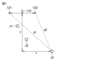
- FIG. 7 is a layout diagram for explaining how to determine the position of an object in the measurement system of embodiment 2.
- FIG. 8 is a waveform diagram for explaining how to determine the position of an object in the measurement system of embodiment 2.
- FIGS. 7 and 8 two-dimensional position determination using two receiving elements 121 and 122 is explained.
- the position (x, y) of object J3 can be identified from distance d1 and distance d2.
- the signal processing unit 130 is configured to calculate the distance d1 to the object J3 based on the latest time tf1 at which the amplitude of the first received signal SR1 exceeds the judgment value St within a certain time tm from the time ts2 at which the first sound wave SS1 is emitted.
- the signal processing unit 130 is configured to calculate the distance d2 from the object J3 based on the latest time tf2 at which the amplitude of the second received signal SR2 exceeds the judgment value St within a certain time tm from the time ts2 at which the first sound wave SS1 is emitted.
- the principle of position detection will be described.
- An example of calculating the position of the farthest object in a certain area when two receiving elements are arranged is shown in Fig. 6 and Fig. 7.
- the distances d1 and d2 from the receiving element 121 and the receiving element 122 to the farthest object in a certain area can be calculated by the following formulas (2) and (3) using the same method as in the first embodiment.
- d1 (tf1-ts)/2C...(2)
- d2 (tf2-ts)/2C...(3)
- a circle of radius d1 centered on receiving element 121 and a circle of radius d2 centered on receiving element 122 intersect at one point on a plane in the forward direction only, so the position (x, y) of the farthest object within a certain area in two-dimensional space can be identified.
- d3 (tf3-ts)/2C...(4)
- a sphere of radius d1 centered on receiving element 121
- a sphere of radius d2 centered on receiving element 122
- a sphere of radius d3 centered on receiving element 123 intersect at a single point in three-dimensional space in the forward direction only, thereby identifying the position (x, y, z) of the farthest object within a certain area in three-dimensional space.
- FIG. 9 is a diagram showing an example in which the measurement system of the second embodiment is applied to an HMD 200.
- a position detection system is installed in an HMD, it is difficult to accurately detect the position of the hand due to reflection from the arm when using a general method for detecting the distance or position of the nearest object.
- a detection target such as a hand is located beyond the screen that the user sees.
- the screen and the sensor transmission/reception unit are placed between the user's eyes and the detection target.
- Within a certain area may be an area with a radius of about 1 m from the HMD 200, assuming that the distance at which an average person extends their arm is 1 m. This makes it possible, for example, to change the position of the pointer displayed on the HMD display and perform operations such as swiping the screen by changing the position of the hand.
- objects J1 and J2 are associated with the arm
- object J3 is associated with the hand.
- the distance d2 to the hand can be measured without the arm having any effect.
- the latest time tf3 at which the waveform of the received signal SR2 exceeds a certain signal magnitude (determination value St) is taken as the sound wave reception time, and the distance to the target is calculated, making it possible to measure the distance d3 to the hand without affecting the arm.
- Embodiment 3 in the measurement system described in embodiment 2, two or more position detection units are arranged, and the position of the farthest object in the first area and the position of the farthest object in the second area are detected from the difference in the reception time of the reflected sound wave by each receiving element.
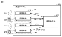
- FIG. 10 is a diagram showing the configuration of a measurement system according to the third embodiment.
- FIG. 11 is a diagram showing an example in which the measurement system according to the third embodiment is applied to an HMD.
- FIG. 12 is a diagram showing how the positions of both hands are detected using the measurement system according to the third embodiment.
- the measurement system 201 shown in FIG. 10 includes a position detection unit TR1, a position detection unit TR2, and a signal processing unit 250.
- the position detection unit TR1 includes a transmitting element 210 that generates a sound wave SS11 for transmission, and a receiving unit 220 that receives sound waves RS11 to RS13 that are reflected from an object from the sound wave SS11.
- the receiving unit 220 includes a receiving element 221, a receiving element 222, and a receiving element 223.
- the signal processing unit 250 causes the transmitting element 210 to transmit a sound wave SS11, receives a receiving signal SR11 corresponding to the sound waves RS11 to RS13 from the receiving element 221, receives a receiving signal SR12 corresponding to the second sound waves RS1 to RS3 from the receiving element 222, and receives a receiving signal SR13 corresponding to the sound waves RS1 to RS3 from the receiving element 223.
- the measurement system 201 also receives reception signals SR21 to SR23 from the position detection unit TR2.
- the position detection unit TR2 includes a transmitting element 230 that generates a sound wave SS12 for transmission, and a receiving unit 240 that receives sound waves RS14 to RS16 that are reflected from the target object from the sound wave SS12.
- the receiving unit 240 includes a receiving element 241, a receiving element 242, and a receiving element 243.
- the signal processing unit 250 causes the transmitting element 230 to transmit sound waves SS12, receives a receiving signal SR21 corresponding to sound waves RS14 to RS16 from the receiving element 241, receives a receiving signal SR22 corresponding to RS14 to RS16 from the receiving element 242, and receives a receiving signal SR23 corresponding to RS14 to RS16 from the receiving element 243.
- the above configuration makes it possible to pinpoint the position of one object in each of two three-dimensional regions.
- a first position detection unit TR1 is disposed at position P1
- a second position detection unit TR2 is disposed at position P2.
- the frequencies were the same, the reflected waves from both hands would be detected by the receiving elements on both the front and sides, making accurate measurements impossible.
- a bandpass filter or similar By changing the frequency of the transmitting elements located on the front and sides, it is possible to use a bandpass filter or similar to separately set the frequencies detected by the receiving elements among the sound waves received. Therefore, even if both hands are brought close to the front and sides at the same time, it is possible to detect their positions independently.
- the frequencies of the transmitting elements can be used.
- the extent to which the frequencies of the transmitting elements are separated must be determined based on the element characteristics, primarily the Q value. In this case, it is necessary to specify that the frequency of the sound waves used by one transmitting element is sufficiently separated from the resonant frequency of the other transmitting element.
- transmission and reception of the transmitting element 210 and the receiving elements 221 to 223 in the position detection unit TR1 can be alternated with transmission and reception of the transmitting element 210 and the receiving elements 221 to 223 in the position detection unit TR1.
- the frame rate will be reduced to less than half.
- Embodiment 4 In the HMD of the third embodiment in which the position detection units TR1 and TR2 are disposed on the front and side, respectively, the position of the hand detected on the front side controls the position of the pointer on the screen, and the position of the other hand detected on the side controls the action of the pointer on the screen. Note that the position of the pointer on the screen may be controlled on the hand position detected on the side, and the action of the pointer on the screen may be controlled on the other hand position detected on the front side.
- the actions are actions that are typically performed with a mouse, such as selecting or dragging. Actions are assigned to correspond to hand movements, such as moving your hand close to the HMD and then moving it away, or moving your hand in a circular motion. This allows for more complex control of the HMD using hand movements.
- the pointer position and actions of an HMD are realized by wearing an inertial force sensor on the hand or by pressing a button held in the hand, but in this embodiment, it is not necessary to wear a sensor on the hand.
- the measurement system 1 shown in FIG. 1 includes a first transmitting element 10 that generates a first sound wave SS1 to be transmitted, a first receiving element 20 that receives second sound waves RS1 to RS3 that are reflected from an object from the first sound wave SS1, and a signal processing unit 30 that causes the first transmitting element 10 to transmit the first sound wave SS1 and receives a first receiving signal SR1 corresponding to the second sound waves RS1 to RS3 from the first receiving element 20.
- a first transmitting element 10 that generates a first sound wave SS1 to be transmitted
- a first receiving element 20 that receives second sound waves RS1 to RS3 that are reflected from an object from the first sound wave SS1
- a signal processing unit 30 that causes the first transmitting element 10 to transmit the first sound wave SS1 and receives a first receiving signal SR1 corresponding to the second sound waves RS1 to RS3 from the first receiving element 20.
- the signal processing unit 30 is configured to calculate the distance to the object based on the latest time tf at which the amplitude of the first receiving signal SR1 exceeds a judgment value St within a certain time tm from the time ts when the first sound wave SS1 is emitted.
- the signal processing unit 130 receives a second receiving signal SR2 corresponding to the second sound wave from the second receiving element 122, and detects the position of the object based on the first receiving signal SR1 and the second receiving signal SR2.
- the measurement system described in paragraph 2 like the measurement system 201 shown in Figures 10 and 11, further includes a second transmission element 230, a third reception element 241, and a fourth reception element 242 in addition to the first transmission element 210 that generates a first sound wave SS1 for transmission, and the first reception element 221 and the second reception element 222 that receive the second sound waves RS1 to RS3 reflected from the first sound wave SS1 by the object.
- the second transmission element 230 is disposed at a position different from the first transmission element 210, and generates a third sound wave SS12 for transmission.
- the third reception element 241 is disposed at a position different from the first reception element 221 and the second reception element 222, and receives a fourth sound wave that is the third sound wave SS12 reflected from the object.
- the fourth reception element 242 is disposed at a position different from the first reception element 221, the second reception element 222, and the third reception element 241, and receives the third sound wave.
- the signal processing unit 250 causes the second transmitting element 230 to transmit a third sound wave SS12, receives a third receiving signal SR21 corresponding to the fourth sound wave from the third receiving element 241, and receives a fourth receiving signal SR22 corresponding to the fourth sound wave from the fourth receiving element 242.
- the signal processing unit 250 is configured to detect the position of the target object based on the first to fourth receiving signals SR11, SR12, SR21, and SR22.
- the first sound wave SS11 and the third sound wave SS12 have different frequencies.
- the first sound wave SS11 and the third sound wave SS12 have different transmission times (emission times, radiation times).
- the first transmitting element 210, the first receiving element 221, and the second receiving element 222 constitute a first position detection unit TR1
- the second transmitting element 230, the third receiving element 241, and the fourth receiving element 242 constitute a second position detection unit TR2.
- the object includes both hands
- the signal processing unit 250 is configured to recognize the position of the first hand detected by the first position detection unit TR1 of both hands as the position of the pointer, and to recognize the position of the second hand detected by the second position detection unit TR2 of both hands as a position indicating an action.
- the present disclosure relates to a head-mounted display including a measurement system according to any one of claims 1 to 6.
Landscapes
- Engineering & Computer Science (AREA)
- Physics & Mathematics (AREA)
- Radar, Positioning & Navigation (AREA)
- Remote Sensing (AREA)
- Computer Networks & Wireless Communication (AREA)
- General Physics & Mathematics (AREA)
- Acoustics & Sound (AREA)
- Measurement Of Velocity Or Position Using Acoustic Or Ultrasonic Waves (AREA)
Priority Applications (2)
| Application Number | Priority Date | Filing Date | Title |
|---|---|---|---|
| PCT/JP2023/011925 WO2024201597A1 (ja) | 2023-03-24 | 2023-03-24 | 測定システムおよびヘッドマウントディスプレイ |
| JP2025509235A JPWO2024201597A1 (https=) | 2023-03-24 | 2023-03-24 |
Applications Claiming Priority (1)
| Application Number | Priority Date | Filing Date | Title |
|---|---|---|---|
| PCT/JP2023/011925 WO2024201597A1 (ja) | 2023-03-24 | 2023-03-24 | 測定システムおよびヘッドマウントディスプレイ |
Publications (1)
| Publication Number | Publication Date |
|---|---|
| WO2024201597A1 true WO2024201597A1 (ja) | 2024-10-03 |
Family
ID=92904057
Family Applications (1)
| Application Number | Title | Priority Date | Filing Date |
|---|---|---|---|
| PCT/JP2023/011925 Ceased WO2024201597A1 (ja) | 2023-03-24 | 2023-03-24 | 測定システムおよびヘッドマウントディスプレイ |
Country Status (2)
| Country | Link |
|---|---|
| JP (1) | JPWO2024201597A1 (https=) |
| WO (1) | WO2024201597A1 (https=) |
Citations (4)
| Publication number | Priority date | Publication date | Assignee | Title |
|---|---|---|---|---|
| JPH0352689U (https=) * | 1989-09-29 | 1991-05-22 | ||
| JPH0666934A (ja) * | 1992-06-03 | 1994-03-11 | Endress & Hauser Gmbh & Co | パルス走行時間方式の距離測定方法および装置 |
| JPH07239384A (ja) * | 1994-02-28 | 1995-09-12 | Mitsubishi Heavy Ind Ltd | 距離センサー |
| US10572024B1 (en) * | 2016-09-28 | 2020-02-25 | Facebook Technologies, Llc | Hand tracking using an ultrasound sensor on a head-mounted display |
-
2023
- 2023-03-24 JP JP2025509235A patent/JPWO2024201597A1/ja active Pending
- 2023-03-24 WO PCT/JP2023/011925 patent/WO2024201597A1/ja not_active Ceased
Patent Citations (4)
| Publication number | Priority date | Publication date | Assignee | Title |
|---|---|---|---|---|
| JPH0352689U (https=) * | 1989-09-29 | 1991-05-22 | ||
| JPH0666934A (ja) * | 1992-06-03 | 1994-03-11 | Endress & Hauser Gmbh & Co | パルス走行時間方式の距離測定方法および装置 |
| JPH07239384A (ja) * | 1994-02-28 | 1995-09-12 | Mitsubishi Heavy Ind Ltd | 距離センサー |
| US10572024B1 (en) * | 2016-09-28 | 2020-02-25 | Facebook Technologies, Llc | Hand tracking using an ultrasound sensor on a head-mounted display |
Also Published As
| Publication number | Publication date |
|---|---|
| JPWO2024201597A1 (https=) | 2024-10-03 |
Similar Documents
| Publication | Publication Date | Title |
|---|---|---|
| JP5615270B2 (ja) | 物体の位置決定 | |
| EP3488184B1 (en) | Echolocation with haptic transducer devices | |
| US8614669B2 (en) | Touchless tablet method and system thereof | |
| KR101850680B1 (ko) | 터치 입력 힘 검출 | |
| JP6404679B2 (ja) | 物体検知装置 | |
| JP3772137B2 (ja) | ポインティング装置 | |
| JP5563153B2 (ja) | 操作装置 | |
| JP6474228B2 (ja) | 物体検知装置 | |
| US20210231507A1 (en) | Measuring apparatus, and measuring method | |
| WO2024201597A1 (ja) | 測定システムおよびヘッドマウントディスプレイ | |
| TWI452322B (zh) | 使用聲波測量物體空間位置的方法及系統 | |
| US20070237029A1 (en) | Frequency matched relative position tracking system | |
| KR20150084756A (ko) | 스마트폰 등에 구비된 센서들을 이용한 위치추적시스템 | |
| KR102667973B1 (ko) | 초음파 센서 장치와 초음파 센서 제어 장치 및 방법 | |
| CN107291308A (zh) | 一种手势识别装置及其识别方法 | |
| JPH06186328A (ja) | 超音波距離測定装置 | |
| JPH06186330A (ja) | 非接触型3次元位置測定装置 | |
| WO2025229882A1 (ja) | 測位システム | |
| WO2023199786A1 (ja) | 情報処理装置、情報処理方法及びプログラム | |
| CA2107198A1 (en) | Method and apparatus for accurate acoustic distance measurement | |
| WO2021145440A1 (ja) | 計測装置、計測方法、及び、プログラム | |
| JP2021113808A (ja) | 計測装置、計測方法、及び、プログラム | |
| JP2003122495A (ja) | 位置検出装置 | |
| KR20110064568A (ko) | 3차원 포인팅 장치 및 방법 | |
| JPH06118170A (ja) | 音響測位装置 |
Legal Events
| Date | Code | Title | Description |
|---|---|---|---|
| 121 | Ep: the epo has been informed by wipo that ep was designated in this application |
Ref document number: 23930238 Country of ref document: EP Kind code of ref document: A1 |
|
| ENP | Entry into the national phase |
Ref document number: 2025509235 Country of ref document: JP Kind code of ref document: A |
|
| WWE | Wipo information: entry into national phase |
Ref document number: 2025509235 Country of ref document: JP |
|
| NENP | Non-entry into the national phase |
Ref country code: DE |
|
| 122 | Ep: pct application non-entry in european phase |
Ref document number: 23930238 Country of ref document: EP Kind code of ref document: A1 |