WO2024195641A1 - 複合タングステン酸化物粒子、近赤外線吸収粒子分散液、および近赤外線吸収粒子分散体 - Google Patents
複合タングステン酸化物粒子、近赤外線吸収粒子分散液、および近赤外線吸収粒子分散体 Download PDFInfo
- Publication number
- WO2024195641A1 WO2024195641A1 PCT/JP2024/009664 JP2024009664W WO2024195641A1 WO 2024195641 A1 WO2024195641 A1 WO 2024195641A1 JP 2024009664 W JP2024009664 W JP 2024009664W WO 2024195641 A1 WO2024195641 A1 WO 2024195641A1
- Authority
- WO
- WIPO (PCT)
- Prior art keywords
- tungsten oxide
- infrared absorbing
- composite tungsten
- oxide particles
- particle dispersion
- Prior art date
- Legal status (The legal status is an assumption and is not a legal conclusion. Google has not performed a legal analysis and makes no representation as to the accuracy of the status listed.)
- Ceased
Links
Images











Classifications
-
- C—CHEMISTRY; METALLURGY
- C01—INORGANIC CHEMISTRY
- C01G—COMPOUNDS CONTAINING METALS NOT COVERED BY SUBCLASSES C01D OR C01F
- C01G41/00—Compounds of tungsten
-
- C—CHEMISTRY; METALLURGY
- C01—INORGANIC CHEMISTRY
- C01G—COMPOUNDS CONTAINING METALS NOT COVERED BY SUBCLASSES C01D OR C01F
- C01G41/00—Compounds of tungsten
- C01G41/006—Compounds containing tungsten, with or without oxygen or hydrogen, and containing two or more other elements
-
- C—CHEMISTRY; METALLURGY
- C01—INORGANIC CHEMISTRY
- C01G—COMPOUNDS CONTAINING METALS NOT COVERED BY SUBCLASSES C01D OR C01F
- C01G41/00—Compounds of tungsten
- C01G41/02—Oxides; Hydroxides
-
- C—CHEMISTRY; METALLURGY
- C09—DYES; PAINTS; POLISHES; NATURAL RESINS; ADHESIVES; COMPOSITIONS NOT OTHERWISE PROVIDED FOR; APPLICATIONS OF MATERIALS NOT OTHERWISE PROVIDED FOR
- C09D—COATING COMPOSITIONS, e.g. PAINTS, VARNISHES OR LACQUERS; FILLING PASTES; CHEMICAL PAINT OR INK REMOVERS; INKS; CORRECTING FLUIDS; WOODSTAINS; PASTES OR SOLIDS FOR COLOURING OR PRINTING; USE OF MATERIALS THEREFOR
- C09D5/00—Coating compositions, e.g. paints, varnishes or lacquers, characterised by their physical nature or the effects produced; Filling pastes
- C09D5/32—Radiation-absorbing paints
-
- C—CHEMISTRY; METALLURGY
- C09—DYES; PAINTS; POLISHES; NATURAL RESINS; ADHESIVES; COMPOSITIONS NOT OTHERWISE PROVIDED FOR; APPLICATIONS OF MATERIALS NOT OTHERWISE PROVIDED FOR
- C09D—COATING COMPOSITIONS, e.g. PAINTS, VARNISHES OR LACQUERS; FILLING PASTES; CHEMICAL PAINT OR INK REMOVERS; INKS; CORRECTING FLUIDS; WOODSTAINS; PASTES OR SOLIDS FOR COLOURING OR PRINTING; USE OF MATERIALS THEREFOR
- C09D7/00—Features of coating compositions, not provided for in group C09D5/00; Processes for incorporating ingredients in coating compositions
- C09D7/40—Additives
- C09D7/60—Additives non-macromolecular
- C09D7/61—Additives non-macromolecular inorganic
-
- C—CHEMISTRY; METALLURGY
- C09—DYES; PAINTS; POLISHES; NATURAL RESINS; ADHESIVES; COMPOSITIONS NOT OTHERWISE PROVIDED FOR; APPLICATIONS OF MATERIALS NOT OTHERWISE PROVIDED FOR
- C09K—MATERIALS FOR MISCELLANEOUS APPLICATIONS, NOT PROVIDED FOR ELSEWHERE
- C09K3/00—Materials not provided for elsewhere
-
- C—CHEMISTRY; METALLURGY
- C01—INORGANIC CHEMISTRY
- C01P—INDEXING SCHEME RELATING TO STRUCTURAL AND PHYSICAL ASPECTS OF SOLID INORGANIC COMPOUNDS
- C01P2004/00—Particle morphology
- C01P2004/60—Particles characterised by their size
- C01P2004/62—Submicrometer sized, i.e. from 0.1-1 micrometer
-
- C—CHEMISTRY; METALLURGY
- C01—INORGANIC CHEMISTRY
- C01P—INDEXING SCHEME RELATING TO STRUCTURAL AND PHYSICAL ASPECTS OF SOLID INORGANIC COMPOUNDS
- C01P2004/00—Particle morphology
- C01P2004/60—Particles characterised by their size
- C01P2004/64—Nanometer sized, i.e. from 1-100 nanometer
Definitions
- the present invention relates to composite tungsten oxide particles, near-infrared absorbing particle dispersions, and near-infrared absorbing particle dispersions.
- near-infrared shielding technologies have been proposed to date that have good visible light transmittance and reduce solar radiation transmittance while maintaining transparency.
- near-infrared shielding technology that uses inorganic conductive fine particles has the advantages of superior near-infrared shielding properties compared to other technologies, low cost, radio wave transmittance, and high weather resistance.
- Patent Document 1 a compound represented by the general formula M x W y O z (wherein M is one or more elements selected from H, He, alkali metals, alkaline earth metals, rare earth elements, Mg, Zr, Cr, Mn, Fe, Ru, Co, Rh, Ir, Ni, Pd, Pt, Cu, Ag, Au, Zn, Cd, Al, Ga, In, Tl, Si, Ge, Sn, Pb, Sb, B, F, P, S, Se, Br, Te, Ti, Nb, V, Mo, Ta, Re, Be, Hf, Os, Bi, and I; W is tungsten; O is oxygen; and 0.001 ⁇ x/y ⁇ 1, 2.2 ⁇ z/y ⁇ 3.0) is dispersed as infrared-shielding material microparticles in a medium such as a resin; and a technique related to a manufacturing method of the infrared-shielding material microparticles is disclosed.
- Patent Document 1 also discloses an
- Patent Document 1 claims that it is possible to produce an infrared shielding material microparticle dispersion that has excellent optical properties, such as more efficient shielding of sunlight, particularly light in the near-infrared region, while at the same time maintaining transmittance in the visible light region. For this reason, the application of the infrared shielding particle dispersion disclosed in Patent Document 1 to various applications such as window glass is being considered.
- Patent Document 1 has proposed a method for synthesizing Cs0.32WO3 nanoparticles by a solid phase method in Non-Patent Document 1.
- the particle size in the synthesis method disclosed in Non-Patent Document 1 was large, and a pulverization process was required to produce nanoparticles. This could increase the number of process steps.
- Patent Document 2 proposes synthesizing potassium cesium tungsten bronze solid solution particles using a plasma torch in a reducing atmosphere.
- Non-Patent Document 2 discloses a method for synthesizing Cs x WO 3 by hydrothermal synthesis.
- the hydrothermal synthesis requires a synthesis time of several tens of hours or more.
- the hydrothermal synthesis has a problem of having a large number of steps, such as a post-treatment step.
- Non-Patent Document 3 discloses a synthesis method based on inductively coupled thermal plasma technology. However, this synthesis method requires the introduction of an inductively coupled thermal plasma device, which increases the introduction and running costs.
- Non-Patent Document 4 discloses a method for synthesizing composite tungsten oxide using a water-solvent flame spray pyrolysis method. However, the infrared absorption characteristics were poor due to the small amount of Cs.
- Non-Patent Document 5 discloses a method for synthesizing composite tungsten oxide using a water-solvent spray pyrolysis method, and discloses a method for synthesizing composite tungsten oxide with little Cs detachment from the particle surface. However, the infrared absorption characteristics were poor.
- Patent Document 3 and Patent Document 4 disclose a method for producing composite tungsten microparticles using the flame spray method.
- composite tungsten oxide particles are useful as near-infrared shielding materials.
- materials that have better visible light transmission and improved infrared shielding performance than conventionally known composite tungsten oxide particles are desirable.
- one aspect of the present invention aims to provide composite tungsten oxide particles that have excellent visible light transmission and infrared shielding properties.
- a composite tungsten oxide particle comprising a composite tungsten oxide
- the composite tungsten oxide is The compound is represented by a general formula MxWyOz (wherein M element is one or more elements selected from alkali metal elements, alkaline earth metal elements, rare earth elements, Mg, Zr, Cr, Mn, Fe, Ru, Co, Rh, Ir, Ni, Pd, Pt, Cu, Ag, Au, Zn, Cd, Al, Ga, In, Tl, Si, Ge, Sn, Pb, Sb, B, F, P, S, Se, Br, Te, Ti, Nb, V, Mo, Ta, Re, Be, Hf, Os, Bi, and I; W is tungsten; O is oxygen; 0.20 ⁇ x/y ⁇ 0.37, 2.2 ⁇ z/y ⁇ 3.3), The crystal system is hexagonal,
- the composite tungsten oxide particles include, in a STEM-HAADF image of the composite tungsten oxide particles from a [001] incidence, spots
- composite tungsten oxide particles with excellent visible light transmission and infrared shielding properties can be provided.
- FIG. 1 is a schematic diagram of a composite material production apparatus that can be suitably used in the method for producing composite tungsten oxide particles of the present embodiment.
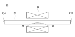
- FIG. 2 is an explanatory diagram of a reduction treatment device used in the reduction treatment step.
- FIG. 3 is a schematic diagram of a near-infrared absorbing particle dispersion liquid.
- FIG. 4 is a schematic diagram of a near infrared absorbing particle dispersion.
- FIG. 5 is a schematic diagram of a near-infrared absorbing laminate.
- FIG. 6 is a schematic diagram of a near-infrared absorbing transparent substrate.
- FIG. 7 is a schematic diagram of the crystal structure of composite tungsten bronze observed at [001] incidence.
- FIG. 8 is an XRD pattern of the composite tungsten oxide particles obtained in Example 1.
- FIG. 9A is a STEM-HAADF image of the composite tungsten oxide particle obtained in Example 1.
- FIG. 9B is a STEM-HAADF image of the composite tungsten oxide particles obtained in Example 1.
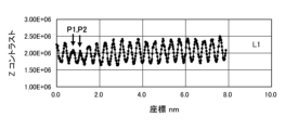
- FIG. 10A is a line profile quantifying the Z contrast of tungsten atoms in line L1 in FIG. 9B.
- FIG. 10B is a line profile quantifying the Z contrast of tungsten atoms in line L2 in FIG. 9B.
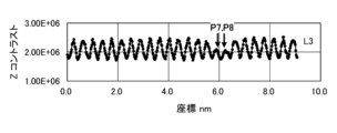
- FIG. 10C is a line profile quantifying the Z contrast of tungsten atoms in line L3 in FIG. 9B.
- FIG. 10D is a line profile quantifying the Z contrast of tungsten atoms in line L4 in FIG.
- FIG. 10E is a line profile quantifying the Z-contrast of tungsten atoms in line L5 in FIG. 9B.
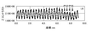
- FIG. 10F is a line profile quantifying the Z contrast of tungsten atoms in line L6 in FIG. 9B.
- FIG. 11A is a STEM-HAADF image of the composite tungsten oxide particle obtained in Comparative Example 1.
- FIG. 11B is a STEM-HAADF image of the composite tungsten oxide particles obtained in Comparative Example 1.
- FIG. 12A is a STEM-HAADF image of the composite tungsten oxide particle obtained in Comparative Example 1.
- FIG. 12B is a line profile quantifying the Z contrast of tungsten atoms in the composite tungsten oxide particles obtained in Comparative Example 1.
- FIG. 12C is a line profile quantifying the Z contrast of tungsten atoms in the composite tungsten oxide particles obtained in Comparative Example 1.
- FIG. 12D is a line profile quantifying the Z contrast of tungsten atoms in the composite tungsten oxide particles obtained in Comparative Example 1.
- FIG. 13A is a transmitted light profile of the near infrared absorbing particle dispersion liquid according to Example 1.
- FIG. 13B is a transmitted light profile of the near infrared absorbing particle dispersion liquid according to Comparative Example 1.
- FIG. 14A is a STEM-HAADF image from [110] incidence for a composite tungsten oxide particle according to Example 1.
- FIG. 14B is a STEM-HAADF image from [110] incidence for the composite tungsten oxide particle according to Example 1.
- FIG. 14A is a STEM-HAADF image from [110] incidence for the composite tungsten oxide particle according to Example 1.
- FIG. 15 is a diagram showing a schematic arrangement of W atoms and Cs atoms in FIG.
- FIG. 16A is an XPS spectrum of W atoms of the composite tungsten oxide particles obtained in Example 1.
- FIG. 16B is an XPS spectrum of W atoms of the composite tungsten oxide particles obtained in Comparative Example 1.
- FIG. 17A is a molar absorption coefficient curve of the composite tungsten oxide particles obtained in Example 1.
- FIG. 17B is a molar absorption coefficient curve of the composite tungsten oxide particles obtained in Comparative Example 1.
- FIG. 18 shows optical profiles of transmittance of dispersions containing the composite tungsten oxide particles of Example 1 and Comparative Example 1.
- FIG. 19A is an explanatory diagram of the change in transmittance before and after ultraviolet ray irradiation of the near infrared ray absorbing particle dispersion obtained in Example 1.
- FIG. 19B is an explanatory diagram of the change in transmittance before and after ultraviolet ray irradiation of the near infrared ray absorbing particle dispersion obtained in Comparative Example 1.
- FIG. 20 is an explanatory diagram of the change in visible light transmittance with respect to the amount of ultraviolet light irradiation for the near infrared absorbing particle dispersions obtained in Example 1 and Comparative Example 1.
- FIG. 19B is an explanatory diagram of the change in transmittance before and after ultraviolet ray irradiation of the near infrared ray absorbing particle dispersion obtained in Comparative Example 1.
- FIG. 20 is an explanatory diagram of the change in visible light transmittance with respect to the amount of ultraviolet light irradiation for the near infrared absorbing particle dispersions obtained in Example 1
- FIG. 21A is an explanatory diagram of the change in visible light transmittance before and after the near infrared absorbing particle dispersion obtained in Example 1 was left in an environment at a temperature of 120° C.
- FIG. 21B is an explanatory diagram of the change in visible light transmittance before and after the near infrared absorbing particle dispersion obtained in Comparative Example 1 was left in an environment at a temperature of 120° C.
- FIG. 22 is an explanatory diagram of the change in visible light transmittance versus the number of days that the near infrared absorbing particle dispersions obtained in Example 1 and Comparative Example 1 were left in an environment at a temperature of 120° C.
- FIG. 21A is an explanatory diagram of the change in visible light transmittance before and after the near infrared absorbing particle dispersion obtained in Example 1 was left in an environment at a temperature of 120° C.
- FIG. 21B is an explanatory diagram of the change in visible light transmittance before and after the near infrared
- FIG. 23A is an explanatory diagram of the change in visible light transmittance before and after the near infrared absorbing particle dispersion obtained in Example 1 was left in an environment of a relative humidity of 90% and a temperature of 85° C.
- FIG. 23B is an explanatory diagram of the change in visible light transmittance before and after the near infrared absorbing particle dispersion obtained in Comparative Example 1 was left in an environment of a relative humidity of 90% and a temperature of 85° C.
- FIG. 24 is an explanatory diagram of the change in visible light transmittance versus the number of days that the near infrared absorbing particle dispersions obtained in Example 1 and Comparative Example 1 were left in an environment of 90% relative humidity and 85° C.
- the present embodiment Specific examples of the composite tungsten oxide particles, near infrared absorbing particle dispersion, and near infrared absorbing particle dispersion according to one embodiment of the present disclosure (hereinafter referred to as "the present embodiment") will be described below with reference to the drawings. Note that the present invention is not limited to these examples, but is indicated by the claims, and is intended to include all modifications within the meaning and scope equivalent to the claims.
- the composite tungsten oxide particles of the present embodiment contain composite tungsten oxide. Note that, the composite tungsten oxide particles may be composed of composite tungsten oxide, but even in this case, it does not exclude the inclusion of inevitable impurities.
- the above composite tungsten oxide is represented by the general formula MxWyOz .
- the M element in the above general formula is an alkali metal element, an alkaline earth metal element, a rare earth element, Mg (magnesium), Zr (zirconium), Cr (chromium), Mn (manganese), Fe (iron), Ru (ruthenium), Co (cobalt), Rh (rhodium), Ir (iridium), Ni (nickel), Pd (palladium), Pt (platinum), Cu (copper), Ag (silver), Au (gold), Zn (zinc), Cd (cadmium), Al (aluminum), Ga (gallium), In (indium), Tl (thallium), It can be one or more elements selected from the group consisting of tungsten, silicon (Si), germanium (Ge), tin (Sn), lead (Pb), antimony (Sb), boron (B), fluorine (F), phosphorus (P), sulfur (S), selenium (Se), bromine (Br), tellurium (Te), titanium (
- Alkaline metal elements include Li (lithium), Na (sodium), K (potassium), Rb (rubidium), Cs (cesium), and Fr (francium).
- Alkaline earth metal elements include Ca (calcium), Sr (strontium), Ba (barium), and Ra (radium).
- Rare earth elements include Sc (scandium), Y (yttrium), La (lanthanum), Ce (cerium), Pr (praseodymium), Nd (neodymium), Pm (promethium), Sm (samarium), Eu (europium), Gd (gadolinium), Tb (terbium), Dy (dysprosium), Ho (holmium), Er (erbium), Tm (thulium), Yb (ytterbium), and Lu (lutetium).
- this composite tungsten oxide is hexagonal.
- the composite tungsten oxide particles contain, in a STEM-HAADF image of the composite tungsten oxide particles from a [001] incidence, spots in which the Z contrast of tungsten atoms has dropped to 95% or less of the average value, in a ratio of 0.01% or more and 10% or less by number.
- Composition The composite tungsten oxide contained in the composite tungsten oxide particles is expressed by the general formula MxWyOz as described above. The M element, W, O, and x, y , and z in the formula have already been described, so description thereof will be omitted here.
- the composite tungsten oxide can have one or more tungsten bronze type crystal structures selected from, for example, tetragonal, cubic, and hexagonal crystal structures.
- the composite tungsten oxide contained in the composite tungsten oxide particles of this embodiment is a hexagonal crystal structure.
- the particles When the composite tungsten oxide has a hexagonal crystal structure, the particles have improved transmission in the visible light range and improved absorption of light in the near-infrared range.
- Composite tungsten oxide also functions as an infrared shielding material when it has a tetragonal or cubic tungsten bronze-type crystal structure.
- the absorption position of light in the near-infrared region tends to change depending on the crystal structure of the composite tungsten oxide.
- the absorption position of light in the near-infrared region tends to move to the longer wavelength side in the tetragonal crystal than in the cubic crystal, and further to the longer wavelength side in the hexagonal crystal than in the tetragonal crystal.
- the absorption of light in the visible light region is the least in the hexagonal crystal, followed by the least in the tetragonal crystal, and among these, the cubic crystal has the greatest absorption of light in the visible light region. Therefore, for applications in which more light in the visible light region is transmitted and more light in the infrared region is shielded, it is preferable to use a composite tungsten oxide having a hexagonal tungsten bronze-type crystal structure.
- the composite tungsten oxide particles when the composite tungsten oxide has a hexagonal crystal structure, the composite tungsten oxide particles have particularly improved light transmittance in the visible light region and light absorption in the near infrared region. For this reason, the composite tungsten oxide particles preferably contain composite tungsten oxide with a hexagonal crystal structure. Furthermore, using one or more elements selected from Cs, Rb, K, Tl, Ba, and In as the M element makes it easier to form a hexagonal crystal. For this reason, the M element preferably contains one or more elements selected from Cs, Rb, K, Tl, Ba, and In, and it is more preferable that the M element contains one or more elements selected from Rb and Cs.
- An octahedron formed from a W (tungsten) atom and six O (oxygen) atoms i.e. an octahedron with O atoms at the vertices and a W atom in the center, is assembled into six octahedrons to form a hexagonal void (tunnel) made up of O atoms.
- An M element is then placed in the void to form one unit, and many of these units are assembled to form a hexagonal crystal structure.
- the mass ratio of M element to W is 0.20 ⁇ x/y ⁇ 0.37, preferably 0.25 ⁇ x/y ⁇ 0.37, and more preferably 0.30 ⁇ x/y ⁇ 0.36.
- the value of x/y is 0.33, and it is considered that M element is arranged in all of the hexagonal gaps. Note that the above x, y, and z mean x, y, and z in the general formula M x W y O z described above, and the same applies below.
- the composite tungsten oxide has a composition in which M element is added to tungsten trioxide (WO 3 ). Since tungsten trioxide does not contain effective free electrons, the ratio of oxygen to 1 mole of tungsten must be less than 3 to achieve the infrared absorption effect. However, in the composite tungsten oxide, free electrons are generated by adding M element, and the infrared absorption effect can be obtained. Therefore, the ratio of oxygen to 1 mole of tungsten can be 3 or less. In addition, the ratio of oxygen to 1 mole of tungsten may exceed 3. However, the crystal phase of WO 2 may cause absorption or scattering of light in the visible light region, which may reduce the absorption of light in the near infrared region. Therefore, from the viewpoint of suppressing the generation of WO 2 , it is preferable that the ratio of oxygen to 1 mole of tungsten is greater than 2.
- the composite tungsten oxide particle of the present embodiment preferably has an average particle size of 800 nm or less. This is because particles with an average particle size of 800 nm or less do not completely block light due to scattering, and can maintain high visibility in the visible light region and efficiently maintain transparency at the same time.In particular, when transparency in the visible light region is important, it is preferable to further consider scattering by particles.
- the average particle size When emphasis is placed on reducing scattering by such particles, it is more preferable for the average particle size to be 200 nm or less, and even more preferable for it to be 100 nm or less.
- a small average particle size reduces scattering of light in the visible light region with wavelengths of 400 nm to 780 nm, due to geometric scattering or Mie scattering, which makes the infrared shielding film of a near-infrared absorbing particle dispersion or the like resemble cloudy glass, preventing clear transparency.
- the average particle size is 200 nm or less, the geometric scattering or Mie scattering is reduced, and the Rayleigh scattering region is reached. In the Rayleigh scattering region, scattered light is reduced in proportion to the sixth power of the average particle size, so scattering is reduced and transparency is improved as the average particle size decreases.
- an average particle size of 100 nm or less is preferable as the scattered light is very little. From the viewpoint of avoiding light scattering, a small average particle size is preferable.
- the composite tungsten oxide particles of this embodiment preferably have an average particle size of 800 nm or less, more preferably 200 nm or less, and even more preferably 100 nm or less.
- the lower limit of the average particle size of the composite tungsten oxide particles of this embodiment is not particularly limited, but is preferably, for example, 1 nm or more, more preferably 5 nm or more, and even more preferably 10 nm or more.
- the average particle size of the composite tungsten oxide particles is preferably 1 nm or more and 800 nm or less, more preferably 5 nm or more and 200 nm or less, even more preferably 10 nm or more and 200 nm or less, and particularly preferably 10 nm or more and 100 nm or less.
- the average particle size of the composite tungsten oxide particles is calculated by measuring the particle size of each composite tungsten oxide particle from a transmission electron microscope image. Specifically, three fields of view are selected at a magnification that includes 200 or more composite tungsten oxide particles in each field of view, the images of the composite tungsten oxide particles in each field of view are binarized, and the average particle size is calculated by image analysis.
- the circle equivalent diameter is calculated from the area of each composite tungsten oxide particle, and is set as the particle diameter of the composite tungsten oxide particle. Then, the particle diameters of all the composite tungsten oxide particles evaluated are added together, and the average particle diameter is calculated by dividing by the number of particles evaluated.In other words, the average particle diameter can be determined as the arithmetic mean value of the particle diameters of the composite tungsten oxide particles evaluated.
- composite tungsten oxide particles can particularly improve visible light transmission and infrared shielding performance by having a moderate amount of minute oxygen vacancies that are difficult to grasp using XRD patterns, etc.
- the composite tungsten oxide particles containing 10% or less of the dark areas in the Z contrast of tungsten atoms (hereinafter also referred to as "W atoms"), the W remaining around the W deficiency region can be oxidized, and the amount of oxygen deficiency can be contained to a degree that is not excessive. Also, by the composite tungsten oxide particles containing 0.01% or more of the dark areas in the Z contrast of W atoms, oxygen deficiencies can be introduced appropriately.
- Dark areas in the Z contrast of W atoms in composite tungsten oxide particles indicate missing W atoms.
- Dark areas in the Z contrast of W atoms refer to spots (points) where the Z contrast of W atoms has fallen to 95% or less of the reference value, based on the average Z contrast of W atoms included in the observation field of the STEM-HAADF image of the composite tungsten oxide particle.
- STEM-HAADF images are of dispersed composite tungsten oxide particles that can be observed with [001] incidence, and particles of a size of several tens of nanometers or more can be selected for observation.
- the size of the observation field can be set to 20 nm square or more and 50 nm square or less.
- FIG. 7 shows the relationship between the crystal structure of the (001) plane of hexagonal Cs0.33WO3 and the W atom/W atomic row (hereinafter also referred to as "W/W row").
- FIG. 7 is a schematic diagram of the crystal structure of composite tungsten bronze observed at [001] incidence.
- FIG. 9A and FIG. 9B show STEM-HAADF images of the Cs0.33WO3 particles obtained in Example 1.
- FIG. 10A to FIG. 10F show the Z-contrast of W atoms in the W atom/W atomic row at lines L1 to L6 shown in FIG. 9B.
- the Z contrast of W atoms can be seen from the image (STEM-HAADF) obtained by observing a sample with a scanning transmission electron microscope in a high angle dark field (STEM-HAADF) and detecting only the transmitted electrons with a large scattering angle among the electrons that have passed through the sample.
- the magnitude of the scattering angle is proportional to the square of the atomic number (Z), so the higher the atomic number of the element, the brighter the contrast. Therefore, it is possible to obtain contrast due to differences in composition and elements.
- composite tungsten bronze it is possible to distinguish between M elements such as Cs and W atoms due to the difference in contrast.
- the difference in contrast intensity at a tungsten column (W column), which is a spot (point) where tungsten is arranged, in the STEM- HAADF image is utilized. If W atoms are vacant, the maximum value of Z contrast at the spot is reduced.
- the vacant site of W atoms on the (001) surface of hexagonal Cs0.33WO3 is shown with a contrast lower than the average value of Z contrast at the spot where W atoms of the W atom/W atomic column are arranged.
- the spot forms a vacant region of W atoms elongated in a columnar shape in the (001) direction. At the largest point, it extends to 10 nm or more in the (001) direction. No vacancies of W atoms connected by 5 nm or more are confirmed on the (001) surface.
- an octahedron 74 is formed with a W atom 71 and six O atoms 72 as a unit, that is, an octahedron 74 with O atoms at the vertices and a W atom 71 in the center is assembled into six hexagonal voids (tunnels) 75 made up of O atoms 72. Note that in Figure 7, circles with the same hatching indicate the same atoms.
- M elements 73 are placed in hexagonal gaps 75 formed by O atoms 72 to form one unit. Furthermore, many of these units come together to form a hexagonal crystal structure.
- the hexagonal gaps 75 are parallel to the (001) plane.
- the (001) plane is also perpendicular to the c-axis.
- the change in the crystal structure of the particles during the synthesis process will be described using Cs0.33WO3 particles as an example of the composite tungsten oxide particles of this embodiment.
- the composite tungsten oxide particles of this embodiment are manufactured through a raw material preparation process, an aerosol formation process, a heat treatment process, and a reduction treatment process, as described below.
- the raw material aerosolized in the aerosol formation process is rapidly heated to 500°C or higher in the heat treatment process, and a reaction that changes the raw material into a composite tungsten oxide by short-term heating is advanced. Then, after heating, the raw material is rapidly cooled to stop the reaction that changes the raw material into a composite tungsten oxide.
- the composite tungsten oxide particles obtained through the heat treatment process contain hexagonal crystals ( Cs0.33WO3 ) and heterophases ( Cs4W11O35 , ( Cs2O ) 0.44WO6 , etc. ). From the STEM-HAADF image observation of the composite tungsten oxide particles, it can be confirmed that they contain a large amount of W atom defects. The W atom deficiency sites become Cs-excess regions and contribute to the formation of a heterogeneous phase.
- the composite tungsten oxide particles containing heterogeneous phases obtained through the heat treatment process are subjected to a reduction process in which oxygen is not supplied, and the M elements Cs, W, and O atoms are rearranged.
- This rearrangement of the atoms changes the particles into composite tungsten oxide particles in which dark areas are observed in the Z contrast of W atoms in STEM-HAADF images from [001] incidence.
- the dark areas in the Z contrast of W atoms in STEM-HAADF images from [001] incidence of composite tungsten oxide particles that have undergone the reduction process are presumed to be traces of the above-mentioned heterogeneous phases and missing W atoms.
- Comparative Example 1 when composite tungsten oxide particles are synthesized by heating the raw materials in a reducing atmosphere for a longer time than in Example 1 above without aerosolizing the raw materials, hexagonal single-phase composite tungsten oxide particles can be obtained by adjusting the atmosphere and heating conditions.
- Figure 11B which shows the evaluation results of Comparative Example 1, composite tungsten oxide particles prepared without aerosolizing the raw materials show almost no dark areas in the Z contrast of W atoms even when observing the STEM-HAADF image from [001] incidence.
- the composite tungsten oxide particles of this embodiment can also have a defect surface in a direction perpendicular to the c-axis in a STEM-HAADF image (prism surface) of the composite tungsten oxide particles from [110] incidence.
- the above-mentioned defect surface is caused by a defect in W atoms. Furthermore, there may be a space in the c-axis direction where there are no atoms of M elements such as cesium and no W atoms.
- Figures 14A and 14B are STEM-HAADF images from [110] incidence of the composite tungsten oxide particle of Example 1.
- a defect surface 141 which is a defect in the basal plane caused by a defect of W atoms with a length of about 30 nm in the direction perpendicular to the c-axis, was confirmed.
- a space 142 with a length of about 3 nm in the c-axis direction where no Cs atoms or W atoms exist was confirmed.
- Figure 14B is an enlarged view of Figure 14A. It is believed that the missing surface 141, which is a defect in the basal plane, and the space 142 along the c-axis direction where no Cs or W is present remain as the interface of the crystallized region when the Cs and W atoms are rearranged within the crystal during the heat treatment process.
- Figure 15 is a schematic diagram showing the arrangement of W atoms and Cs atoms in Figures 14A and 14B.
- the composite tungsten oxide particles of this embodiment dark areas are observed in the Z contrast of W atoms in the STEM-HAADF image from [001] incidence, which is presumed to be a trace of W atom defects before the reduction treatment process. It can be confirmed that the composite tungsten oxide particles of this embodiment before the reduction treatment process in the synthesis process contain a large amount of W atom defects.
- the W atom defects are Cs-rich regions, which contribute to the formation of a different phase other than hexagonal crystals.
- a defect plane may occur in the direction perpendicular to the c-axis, that is, a defect in the (001) plane, which is the basal plane. It is believed that the presence of these defects promotes the rearrangement of W atoms in the reduction treatment process to maintain the hexagonal crystal structure. It is believed that in the process of rearrangement of W atoms to maintain the hexagonal crystal structure, defects (defect planes) of W atoms are generated on the prism surface, and the hexagonal crystal structure is maintained in the areas where no defects occur.
- x, y, and z refer to x, y, and z in the general formula of the composite tungsten oxide particles described above.
- the mass ratio of the M element to the W element is in the range of 0.20 ⁇ x/y ⁇ 0.37, preferably 0.25 ⁇ x/y ⁇ 0.37, and more preferably 0.30 ⁇ x/y ⁇ 0.36.
- the mass ratio of the M element is in the range of 0.20 ⁇ x/y ⁇ 0.37, the rearrangement of the W atoms may cause defects on the prism surface, but the composite tungsten oxide particles can maintain the hexagonal structure and have excellent infrared absorption properties.
- the amount of M element is small, such as when x/y is less than 0.20, it is difficult to form a hexagonal crystal structure, and even if a hexagonal crystal structure is formed, there are few free electrons supplied to the 5d orbital of the W atom, resulting in poor infrared absorption characteristics.
- heterogeneous phases such as pyrochlore phases are generated in the process of rearrangement of W atoms due to the excess M element atoms, and band-shaped defects of W atoms with a length of 10 nm or more also occur on the basal plane of the composite tungsten oxide particle. It is believed that when a vacant region of W atoms with a length of 10 nm or more is formed on the basal plane, the vacant region begins to form periodically, and heterogeneous phases such as pyrochlore phases are stabilized.
- the composition of the M element source and the W element source may be biased in the raw material preparation process described later.
- the substance amount ratio (x/y) of the M element and the W element may be larger than 0.37 in some parts, and the basal surface of some particles of the obtained composite tungsten oxide particles may have a strip-shaped W atom defect with a length of 10 nm or more.However, if the number ratio of particles with such defects is less than 20%, the infrared absorption properties will not be inferior.
- the W atoms of the composite tungsten oxide particles that absorb infrared rays have the electronic states of W5 + and W6 + due to oxygen vacancies.
- the oxidation state can be evaluated by separating the intensity of the 4f orbital of the W atoms in the XPS spectrum into the intensity due to W6 + and W5 + .
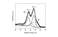
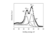
- the composite tungsten oxide particles according to Example 1, which is an example of the composite tungsten oxide particles of this embodiment, can be confirmed to have a more advanced oxidation state than the conventional composite tungsten oxide particles listed in Comparative Example 1 by separating the XPS spectrum.
- FIG. 16A is a 4f profile of W atoms by XPS of the composite tungsten oxide particles according to Example 1.
- FIG. 16B is a 4f profile of W atoms by XPS of the cesium tungsten composite oxide particles according to Comparative Example 1.
- W 6+ has a 4f 7/2 peak in the binding energy range of 34 eV to 36 eV and a 4f 5/2 peak in the binding energy range of 36 eV to 38 eV.
- W 5+ has a 4f 7/2 peak in the binding energy range of 32 eV to 34 eV and a 4f 5/2 peak in the binding energy range of 35 eV to 37 eV.
- the peak interval between W4f 7/2 and W4f 5/2 is fixed to 2.18 eV
- the peak area ratio is fixed to 0.75
- a Gaussian distribution or Lorentz distribution is applied to fit the profile measured by the least square method, so that XPS peak separation can be performed.
- the oxidation state of the W atoms in the composite tungsten oxide particles can be known.
- the background of the profile is removed, and the half-widths of W4f 7/2 and W4f 5/2 are made to match.
- the proportion of W5 + to the total of W6 + and W5 + intensities was 24.9%, whereas it was 25.96% in the composite tungsten oxide particles according to Comparative Example 1. Due to the separation of the W6 + and W5 + intensities of XSP, the composite tungsten oxide particles of Example 1, the profile of which is shown in Fig. 16A, have a lower proportion of W5 + , i.e., a higher proportion of W6 + , than the composite tungsten oxide particles of Comparative Example 1, the profile of which is shown in Fig. 16B, which means that oxidation has progressed further.
- Example 1 the reason why there is little W5 + and oxidation is advanced is presumably because the W atoms in the crystal are stabilized by bonding with oxygen due to the presence of W vacancies formed in the c-axis direction or the basal plane direction as shown in Figures 11A and 11B or Figures 14A and 14B.
- the composite tungsten oxide particles of this embodiment can be manufactured by aerosolizing the raw material and then carrying out heat treatment, etc.
- the composite tungsten oxide particles manufactured by such a manufacturing method involving aerosolization of the raw material tend to be more oxidized than the composite tungsten oxide particles obtained by synthesis using a conventionally known solid phase method and pulverization, etc.
- Peak separation and integrated intensity of localized surface plasmon absorption and polaron absorption of composite tungsten oxide particles affects the optical properties.
- the localized surface plasmon absorption exhibits anisotropy with respect to the c-axis. Specifically, in the case of composite tungsten oxide particles, the localized surface plasmon absorption is classified into localized surface plasmon resonance absorption perpendicular to the c-axis (LSPR ⁇ ) and localized surface plasmon resonance absorption parallel to the c-axis (LSPR//).
- LSPR ⁇ localized surface plasmon resonance absorption perpendicular to the c-axis
- LSPR// localized surface plasmon resonance absorption parallel to the c-axis
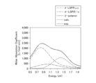
- composite tungsten oxide particles have three absorption components: absorption due to localized surface plasmon resonance in a direction perpendicular to the c-axis (vertical direction) (LSPR ⁇ ), absorption due to localized surface plasmon resonance in a direction parallel to the c-axis (parallel direction) (LSPR//), and polaron absorption. Therefore, the molar absorption coefficient curve of composite tungsten oxide particles can be separated into three absorption curves.
- the wavelength on the horizontal axis of the molar absorption coefficient curve is converted to energy (eV), and the molar absorption coefficient curve is fitted with a Gaussian distribution and a Lorentzian distribution based on Mie scattering theory. Then, the absorption curve is separated into an absorption curve due to localized surface plasmon resonance in a direction perpendicular to the c-axis (LSPR ⁇ ), an absorption curve due to localized surface plasmon resonance in a direction parallel to the c-axis (LSPR//), and an absorption curve due to polaron absorption.
- LSPR ⁇ localized surface plasmon resonance in a direction perpendicular to the c-axis
- LSPR// an absorption curve due to localized surface plasmon resonance in a direction parallel to the c-axis
- the absorption curve due to localized surface plasmon resonance perpendicular to the c-axis (LSPR ⁇ ), the absorption curve due to localized surface plasmon resonance parallel to the c-axis (LSPR//), and the absorption curve due to polaron absorption are obtained, and the average value (peak energy (wavelength)) of the Gaussian distribution and Lorentzian distribution can be determined.
- Each Gaussian distribution is expressed by formula (1).
- A is the peak intensity
- b is the average value
- E is the energy
- c is the standard deviation.
- Equation (2) E is the energy, b is the average value, and d is a constant.
- FIG. 17A shows the molar absorption coefficient curve of the composite tungsten oxide particles according to Example 1, which is an example of the composite tungsten oxide particles of this embodiment.
- FIG. 17B shows the molar absorption coefficient curve of the composite tungsten oxide particles according to Comparative Example 1, which is an example of the composite tungsten oxide particles synthesized by a conventionally known solid phase method and obtained by pulverization.
- Table 2 shows the peak positions, peak intensities, and integrated intensities of the absorption curves of the three absorption elements.
- Table 3 shows the ratios of the integrated intensities of the absorption curves of the three absorption elements to the integrated intensity of the molar absorption coefficient curve.
- FIGS. 17A and 17B are examples, and the absorption curves in each figure are illustrative and are not limited to these absorption curves, but the composite tungsten oxide particles of this embodiment show a similar tendency to the molar absorption coefficient curve shown in FIG. 17A.
- the absorption peak in the localized surface plasmon resonance (LSPR ⁇ ) absorption curve in the direction perpendicular to the c-axis of the composite tungsten oxide particle of Example 1 shown in Figure 17A is 0.86 eV (wavelength 1435 nm), and the integrated intensity of the absorption curve is 96015.38 [L eV/(mol cm)].
- the absorption peak in the absorption curve of the localized surface plasmon resonance (LSPR//) parallel to the c-axis is 1.20 eV (wavelength 1030 nm), and the integrated intensity of the absorption curve is 33042.00 [L eV/(mol cm)].
- the absorption peak in the polaron absorption curve is 1.26 eV (wavelength 985 nm), and the integrated intensity of the absorption curve is 12265.60 [L eV/(mol cm)].
- the percentage of the integrated intensity of the polaron absorption curve among the integrated intensities of the three absorption curves in the molar extinction coefficient curve shown in Figure 17A is 8.7%.
- the composite tungsten oxide particles of Example 1 are synthesized by aerosolization followed by heat treatment, etc., and the integrated intensity of the polaron absorption is reduced compared to composite tungsten oxide particles synthesized by the conventionally known solid-phase method.
- Figure 17B shows the molar absorption coefficient curve of the composite tungsten oxide particles according to Comparative Example 1, which were synthesized by a conventional solid-phase method and then pulverized.
- the absorption peak in the localized surface plasmon resonance (LSPR ⁇ ) absorption curve in the direction perpendicular to the c-axis is 0.80 eV (wavelength 1550 nm), and the integrated intensity of the absorption curve is 78843.30 [L eV/(mol cm)].
- the absorption peak in the absorption curve of the localized surface plasmon resonance (LSPR//) parallel to the c-axis is 1.00 eV (wavelength 1240 nm), and the integrated intensity of the absorption curve is 20209.67 [L eV/(mol cm)].
- the absorption peak in the polaron absorption curve is 1.40 eV (wavelength 885 nm), and the integrated intensity of the absorption curve is 31174.01 [L eV/(mol cm)].
- the composite tungsten oxide particles of Example 1 have weaker polaron absorption than the composite tungsten oxide particles of Comparative Example 1. This is also shown by the fact that the peak value of the polaron absorption curve appearing at 1.26 eV (wavelength 985 nm) of the composite tungsten oxide particles of Example 1 is weaker than the peak value of the polaron absorption appearing at 1.40 eV (wavelength 885 nm) of the composite tungsten oxide synthesized by the solid-phase method.
- the composite tungsten oxide particles of Example 1 have a high ratio of integrated intensity of the absorption curves of LSPR ⁇ and LSPR//, which are absorption due to localized surface plasmon resonance.
- the ratio of integrated intensity of the absorption curve of LSPR// in the composite tungsten oxide particles of Example 1 is higher than the ratio of integrated intensity of the absorption curve of LSPR// in the composite tungsten oxide particles of Comparative Example 1, which were synthesized by the solid phase method and crushed.
- the integrated intensity of each of the three types of absorption curves is the integrated intensity at 0.5 eV or more and 2.0 eV or less (wavelength 620 nm or more and 2500 nm or less).
- the integrated intensity of the three absorption elements localized surface plasmon resonance in a direction perpendicular to the c-axis (LSPR ⁇ ), localized surface plasmon resonance in a direction parallel to the c-axis (LSPR//), and polaron absorption in the above range.
- absorption peaks appear in the order of localized surface plasmon resonance in a direction perpendicular to the c-axis, localized material plasmon absorption in a direction parallel to the c-axis, and polaron absorption.
- absorption due to polarons appears in the high-energy region (the short-wavelength side of the near-infrared region).
- the absorption by polarons in the composite tungsten oxide particles is due to the W5 + of the W atoms in the crystals that constitute the particles.
- the composite tungsten oxide particles of the present embodiment have a small amount of W5 + due to oxygen deficiency, and therefore, when peak separation is performed on the molar absorption coefficient curve, the proportion of polaron absorption is smaller than that of conventionally known composite tungsten oxide particles.
- the molar absorption coefficient of the powder that constitutes the composite tungsten oxide particles in the dispersion or dispersion liquid can be known.
- the molar absorption coefficient of the powder that is composed of the composite tungsten oxide particles of this embodiment is preferably 2600 L/(mol cm) or more, and more preferably 2800 L/(mol cm) or more.
- the molar absorption coefficient will be less than 2000 L/(mol cm).
- the 18 is an optical profile of the transmittance of a dispersion containing 0.5 g/m 2 of the composite tungsten oxide particles according to Example 1 and a dispersion containing 0.5 g/m 2 of the composite tungsten oxide particles according to Comparative Example 1, which is an example of a conventionally known composite tungsten oxide particle.
- the molar absorption coefficient of the composite tungsten oxide particles according to Example 1, which was obtained from the optical profile of the transmittance shown in FIG. 18, is 3000 L/(mol cm).
- the molar absorption coefficient of the composite tungsten oxide particles according to Comparative Example 1 is 2500 L/(mol cm). As shown in FIG.
- the transmittance of the composite tungsten oxide particles according to Example 1, which is an example of the composite tungsten oxide particles of this embodiment, is low from the wavelength of about 900 nm to the wavelength of about 1680 nm, that is, it can be seen that the effect of absorbing near infrared rays is high.
- (6) Change in Optical Properties of Composite Tungsten Oxide Particles The composite tungsten oxide of the present embodiment exhibits excellent optical properties due to its crystal structure and oxidation state.
- One of the excellent optical properties of the composite tungsten oxide of this embodiment is that the transmittance is not easily reduced after irradiating a dispersion in which the composite tungsten oxide particles of this embodiment are dispersed in a resin matrix with ultraviolet light.
- the phenomenon of reduced transmittance is a coloring phenomenon of the composite tungsten oxide particles due to photochromism.
- FIG. 19A shows the change in transmittance before and after ultraviolet light is irradiated onto the near-infrared absorbing particle dispersion of Example 1, which is an example of a dispersion in which the composite tungsten oxide particles of this embodiment are dispersed in a solid medium.
- FIG. 19B shows the change in transmittance before and after ultraviolet light irradiation of a near-infrared absorbing particle dispersion according to Comparative Example 1, which is an example of a dispersion using cesium tungsten composite oxide particles obtained by synthesis and pulverization using a conventionally known solid-phase method.
- FIG. 20 shows the change in visible light transmittance (VLT) with respect to the amount of UV irradiation for both dispersions.
- VLT visible light transmittance
- the composite tungsten oxide particles and near-infrared absorbing particle dispersion of this embodiment are also characterized by their low transmittance even when left in a high-temperature environment or a high-temperature, high-humidity environment.
- FIG. 21A shows the change in transmittance before and after leaving the near-infrared absorbing particle dispersion of Example 1, which is an example of a dispersion of composite tungsten oxide particles of this embodiment, in an environment at a temperature of 120° C. for 19 days.
- Figure 21B shows the change in transmittance before and after leaving a dispersion in a resin matrix in which composite tungsten oxide particles according to Comparative Example 1, which were synthesized and pulverized using a conventional solid-phase method, in an environment at a temperature of 120°C for 19 days.
- FIG. 22 shows the relationship between the number of days that the near-infrared absorbing particle dispersion of Example 1, which is an example of a dispersion of composite tungsten oxide particles according to this embodiment, and the near-infrared absorbing particle dispersion of Comparative Example 1 were left in an environment at a temperature of 120° C. and the visible light transmittance (VLT).
- VLT visible light transmittance
- the near infrared absorbing particle dispersion according to Example 1 using the composite tungsten oxide particles of this embodiment shows almost no change in transmittance even when placed in an environment at a temperature of 120°C
- the near infrared absorbing particle dispersion using the composite tungsten oxide particles of Comparative Example 1 shows an increase in transmittance in both the visible light region and the infrared region.
- the increase in transmittance in an environment at a temperature of 120°C is considered to be caused by the oxidation of the composite tungsten oxide particles.
- the composite tungsten oxide particles of this embodiment are used, the increase in transmittance is small because there is little W5 + and few oxygen vacancies, so there is little room for further oxidation.
- FIG. 23A shows the change in transmittance before and after the near-infrared absorbing particle dispersion of Example 1, which is an example of a dispersion of composite tungsten oxide particles of this embodiment, was left in an environment of 90% relative humidity and 85°C for 13 days.
- Figure 23B shows the change in transmittance before and after leaving a dispersion in a resin matrix in which composite tungsten oxide particles according to Comparative Example 1, which were synthesized and pulverized using a conventional solid-phase method, for 13 days in an environment of 90% relative humidity and 85°C.
- Figure 24 shows the relationship between the number of days that the dispersions of Example 1 and Comparative Example 1 were left in an environment of 90% relative humidity and 85°C temperature and the visible light transmittance (VLT).
- Example 1 which uses the composite tungsten oxide particles of this embodiment, shows almost no change in transmittance even when placed in an environment of 90% relative humidity and 85°C temperature.
- the dispersion using the composite tungsten oxide particles of Comparative Example 1 shows an increase in transmittance in both the visible light region and the infrared region.
- the near-infrared absorbing particles of this embodiment can be made to have excellent visible light transmission and infrared shielding properties.
- the composite tungsten oxide particles of this embodiment can be a dispersion in a solvent or a dispersion in a solid medium.
- the dispersion or dispersion has an excellent infrared shielding effect, in which the transmittance peak in the wavelength region of 500 nm to 600 nm can be 75% or more, and the transmittance bottom in the near-infrared region can be 5% or less.
- the dispersion or dispersion using the composite tungsten oxide particles of this embodiment can transmit red light with a wavelength of around 800 nm, compared to the dispersion of the composite tungsten oxide particles shown in Comparative Example 1. Therefore, it can also contribute to improving the color tone of the dispersion or dispersion using the composite tungsten oxide particles.
- a transmittance of 50% or more at a wavelength of 700 nm and a transmittance of 30% or more at a wavelength of 800 nm can be achieved. Therefore, by using the composite tungsten oxide particles of this embodiment, a dispersion or dispersion can be obtained that has a more neutral color tone of the transmitted color while suppressing the solar radiation transmittance, and can also ensure the transmittance of the sensor wavelength.
- Method of producing composite tungsten oxide particles An outline of the method for producing the composite tungsten oxide particles of this embodiment will be described.
- the method for producing composite tungsten oxide particles of this embodiment can produce the composite tungsten oxide particles described above, so the points that have already been explained will not be explained here. Note that this merely shows an example of the configuration of the method for producing composite tungsten oxide particles, and the method for producing composite tungsten oxide particles described above is not limited to the following example configuration.
- the manufacturing method of the composite tungsten oxide particles of this embodiment is preferably a method capable of directly synthesizing composite tungsten oxide particles having a particle diameter of 1 ⁇ m or less. If composite tungsten oxide particles having a particle diameter of 1 ⁇ m or less can be directly synthesized, it is possible to obtain fine particles that are less susceptible to damage caused by crushing or dispersion, for example composite tungsten oxide particles having a particle diameter of 800 nm or less.
- the preferred method for directly synthesizing composite tungsten oxide particles with a particle size of 1 ⁇ m or less is a manufacturing method in which the particles are synthesized through a heat treatment process in which an aerosol of raw material containing an M element source and a tungsten element source is supplied to an electric furnace, flame, or plasma.
- the method for producing composite tungsten oxide particles of this embodiment can include the following raw material preparation process, aerosol formation process, heat treatment process, and reduction treatment process.
- a raw material containing an M element source and a tungsten element source can be prepared.
- the raw materials prepared in the raw material preparation process can be turned into aerosols.
- the aerosolized raw materials can be heat treated in the reaction field.
- the particles obtained in the heat treatment step can be reduced in an atmosphere containing a reducing gas.
- a source material including an M element source and a tungsten element source (hereinafter also referred to as a "W element source”) can be prepared.
- the raw materials can be blended and prepared so that the ratio of the amount of substance of the M element to the amount of substance of the W element contained in the raw materials corresponds to the composition of the desired composite tungsten oxide particles.
- the state of the raw materials prepared in the raw material preparation process is not particularly limited, and may be liquid or powder, and it is preferable that an aerosol can be formed by spraying, etc.
- an aerosol refers to a mixture of tiny liquid or solid particles suspended in gas and the surrounding gas.
- the raw material can be prepared, for example, by preparing a solution containing an M element source and a W element source.
- a solution containing an M element source and a solution containing a W element source can be prepared in advance, and the two solutions can be mixed in the raw material preparation process to produce a raw material mixed solution.
- the raw material can also be supplied in the form of droplets to the heat treatment process described below.
- the solution containing the M element source and the solution containing the W element source can be mixed immediately before being supplied to a droplet formation section (droplet formation means) that forms the droplets, or in the droplet formation section, to carry out the raw material preparation process. Then, in the droplet formation section, the aerosol formation process described below can be carried out.
- both solutions in advance As described above, it is preferable to prepare both solutions in advance as described above and mix them just before the aerosol formation process.
- the ratio of the amounts of substance of the M element and the W element in the raw material can be adjusted to the desired range by adjusting the concentrations of both solutions and the delivery speeds of both solutions to the droplet formation section.
- the aerosol formation process and the raw material preparation process do not need to be clearly separated, and both processes can be carried out continuously.
- the specific method of mixing is not particularly limited, and any method can be used.
- the W element source is not particularly limited, and may be any raw material containing tungsten, such as tungsten alone or a tungsten compound.
- a tungsten salt or the like may be used, and for example, hexacarbonyl tungsten may be preferably used. Hexacarbonyl tungsten may be expressed as W(CO) 6.
- an organic solution containing the W element source may be preferably used because of ease of handling.
- the M element source is not particularly limited, and may be any raw material containing the M element, such as the M element alone or a compound containing the M element.
- a solution containing the M element source for example, a solution of a salt containing the M element may be used.
- the type of salt of the M element that is the M element source is not particularly limited, and for example, one or more types selected from carbonates, acetates, nitrates, hydroxides, etc. of the M element may be used.
- an ethanol solution containing an M element source can be preferably used because of its ease of handling.
- one or more salts selected from carbonates, acetates, nitrates, hydroxides, etc. can be used as the salt of the M element source, but acetates are particularly suitable. This is because cesium acetate is particularly easy to dissolve in ethanol.
- the ratio of M element to 1 mole of tungsten element in the resulting composite tungsten oxide i.e., the doping amount
- the doping amount is determined by the ratio of the W element source and the M element source when forming the raw material mixture solution. Therefore, the doping amount can be controlled, for example, by the concentration of the solution containing the W element source or the concentration of the solution containing the M element source.
- the concentration of the W element source contained in the solution containing the W element source i.e., the concentration of the salt of the W element
- the tungsten concentration of the solution containing the W element source is preferably 0.001 mol/L or more and 10 mol/L or less, more preferably 0.01 mol/L or more and 10 mol/L or less, and even more preferably 0.01 mol/L or more and 1 mol/L or less. This is because by making the tungsten concentration of the solution containing the W element source 0.001 mol/L or more, the production amount of composite tungsten oxide particles per unit time can be sufficiently ensured, and for example, a sufficient amount can be recovered by a filter or the like, and productivity can be increased.
- the tungsten concentration of the solution containing the W element source 10 mol/L or less, reprecipitation of the dissolved W element source is suppressed, the generated particles are suppressed from agglomerating, and for example, coarse composite tungsten oxide particles having a particle diameter larger than 1 ⁇ m can be suppressed from being mixed in.
- additives such as agents for adjusting the pH and surfactants can be added to the solution containing the W element source.
- the concentration of the M element source contained in the solution containing the M element source is not particularly limited, and can be selected according to the desired composition of the composite tungsten oxide particles to be produced, the concentration of the W element source contained in the solution containing the W element source, etc.
- any other components can be added to the raw material mixture solution.
- the raw material may be solid, for example, powder.
- the raw material when it is powder, it can be prepared, for example, by mixing a powder of an M element compound with a powder of a tungsten compound.
- a tungsten compound powder can be added to a solution containing an M element source, and stirred, and the solvent can be removed by drying or the like to obtain a precursor powder, which can then be used as the raw material.
- the W element source is not particularly limited, and a tungsten salt or the like can be used.
- a tungsten salt or the like can be used.
- H 2 WO 4 or ammonium paratungstate can be preferably used.
- H 2 WO 4 the elements other than tungsten are H (hydrogen) and O (oxygen), and the elements other than tungsten are discharged outside the system in the heat treatment process described later. Therefore, by using H 2 WO 4 as a W element source, composite tungsten oxide particles with reduced impurity contamination can be obtained, and therefore it can be preferably used.
- the M element source for example, a powder of a salt containing the M element can be used.
- the type of salt containing the M element is not particularly limited, but for example, one or more types selected from carbonates, acetates, nitrates, hydroxides, etc. of the M element can be used.
- the M element is cesium
- one or more selected from carbonates, acetates, nitrates, hydroxides, etc. can be used, with carbonates being particularly preferred.
- Aerosol Formation Step it is preferable to supply the raw material prepared in the raw material preparation step in the form of an aerosol to the heat treatment step. Specifically, it is preferable to transport the aerosol by a carrier gas such as oxygen and to subject it to the heat treatment step.
- the method for producing composite tungsten oxide particles of this embodiment can also include an aerosol formation process in which the raw material is converted into an aerosol containing droplets or particles of the raw material.
- the means and method for forming the aerosol in the aerosol formation process are not particularly limited and can be selected depending on the state of the raw materials, etc.
- an aerosol can be formed by spraying the raw liquid toward a carrier gas using various atomizers such as centrifugal atomizers or two-fluid nozzles. Droplets can also be formed by irradiating the liquid with ultrasonic waves.
- the aerosol can be formed by a device that creates a dispersed state of the raw material powder and supplies the powder into an airflow.
- the aerosol can be formed by an aerosol forming device that includes an agitating section such as a rotating brush or agitating blade, and a powder supplying section that includes a piston or screw feeder that sends the raw material to the agitating section.
- the raw material powder supplied from the powder supplying section is dispersed into particles that make up the powder in the agitating section, and an aerosol can be generated from the raw material powder by sending each particle into a carrier gas.
- the agitating section allows the rotation speed of the brush or agitating blade to be selected so that the raw material powder can be dispersed into particles, and it is preferable to rotate it at high speed.
- the size of the droplets formed is not particularly limited, but the diameter of the droplets is preferably 100 ⁇ m or less, more preferably 10 ⁇ m or less, and even more preferably 5 ⁇ m or less.
- the droplet diameter 100 ⁇ m or less it is possible to prevent the obtained composite tungsten oxide particles from becoming coarse, and it is possible to obtain composite tungsten oxide particles on the order of nanometers.
- the lower limit of the size of the droplets formed in the aerosol formation process is not particularly limited. However, since it is difficult to form droplets that are too small and there is a risk of reduced productivity, it is preferable that the size be, for example, 1 ⁇ m or more.
- the size of the particles is not particularly limited, but the diameter of the particles is preferably 100 ⁇ m or less, more preferably 10 ⁇ m or less, and even more preferably 3 ⁇ m or less. By making the diameter of the particles 100 ⁇ m or less, it is possible to perform heat treatment more reliably to the inside of the particles. The diameter of the particles can be measured in the same way as the particle diameter of the composite tungsten oxide particles described above.
- (1-3) Heat Treatment Step In the heat treatment step, the raw material is heat treated to process the raw material into composite tungsten oxide particles. The heat treatment may be performed at a temperature of 500°C or higher, and the configuration of the heat source is not particularly limited.
- the heat treatment step can be performed by a method of guiding the raw material into a flame using a carrier gas, a method of guiding the raw material into a tubular electric furnace, a method of guiding the raw material into plasma, or the like.
- the heat treatment temperature can be 500°C or higher.
- the composite tungsten oxide particles obtained after the heat treatment process contain appropriate W atom defects and heterogeneous phases, so that composite tungsten oxide particles containing dark areas due to the Z contrast of W atoms can be obtained after the reduction process. Therefore, conditions such as the heat treatment temperature can be selected so that the composite tungsten oxide particles obtained after the heat treatment process have appropriate W atom defects and heterogeneous phases, and composite tungsten oxide particles in which spots with reduced Z contrast of W atoms are confirmed after the reduction process are produced. For this reason, it is preferable to perform a preliminary test or the like and select the supply rate of the raw materials in the heat treatment process, the heat treatment temperature, etc. so that the desired ratio of dark areas in the Z contrast of W atoms is included after the reduction process. It is preferable to select conditions such as the heat treatment temperature so that heterogeneous phases can be reduced and removed after the reduction process.
- the heat treatment temperature should be 500°C or higher as long as it is possible to proceed with the reaction between the tungsten and the M element, but it is preferably 550°C or higher, and more preferably 1000°C or higher. There is no particular upper limit to the heat treatment temperature, but from the viewpoint of reducing energy consumption, it is preferably 4000°C or lower.
- a flame can be used as described above, and the raw material can be heat treated using a flame.
- the particle size of the resulting composite tungsten oxide particles can be selected.
- the raw material droplets move through the flame by a carrier gas such as oxygen gas.
- a carrier gas such as oxygen gas.
- the organic solvent containing the raw material tungsten source and M element source is burned, and the solvent is decomposed by the combustion reaction.
- the heat generated by the combustion reaction contributes to the decomposition reaction of tungsten and M element, and precipitates during the cooling process in the tail flame of the flame field.
- the W element source can be tungsten hexacarbonyl
- the M element source can be cesium acetate when the M element is cesium, and these salts decompose in the heat treatment process.
- W is likely to precipitate as WO6
- Cs is unlikely to form an oxide as a monomer, and some of it passes through the filter and is discharged to the outside of the system without being precipitated as nano-sized powder.
- tungsten reacts with the M element during the decomposition process of the solute portion to form a composite tungsten oxide.
- the conditions for forming the flame are not particularly limited, but the flame can be formed, for example, using a mixed gas containing oxygen and a hydrocarbon.
- a flame with a stable temperature can be formed, and composite tungsten oxide particles can be produced with reduced variation in particle size, etc.
- the volumetric ratio of the flow rates of propane and oxygen (burner) in the gas mixture is 5 to 8 oxygen per 1 propane, and the flow rate of propane is in the range of 0.5 to 2 L/min. This is because, when the flow rate of propane is 1, by setting the flow rate of oxygen to 5 or more, the combustion of propane, which is a flammable gas, can be sufficiently promoted. However, it is preferable to supply 8 or less oxygen per 1 propane to avoid an excessive supply of oxygen.
- the heat treatment temperature of the flame reaction field also affects the particle size of the resulting composite tungsten oxide particles.
- the composite tungsten oxide particles obtained by the heat treatment can be recovered, for example, by using a filter.
- the inventors of the present invention have conducted research and found that the composite tungsten oxide particles can exhibit infrared absorbing properties by further carrying out a reduction treatment step in which the composite tungsten oxide particles obtained through a heat treatment step are subjected to a reduction treatment.
- the method for producing composite tungsten oxide particles of this embodiment can also have a reduction treatment step in which the particles obtained in the heat treatment step are reduced in an atmosphere containing a reducing gas.
- the method for producing composite tungsten oxide particles of this embodiment can have a reduction treatment step in which the particles obtained in the heat treatment step are reduced in an atmosphere containing a reducing gas at a temperature in the range of more than 400°C and less than 700°C after the heat treatment step.
- the conditions for the reduction treatment are not particularly limited, but it is preferable to select the conditions for the reduction treatment so that when the composite tungsten oxide particles after the reduction treatment are analyzed by X-ray diffraction pattern, the crystal structure does not change before and after the reduction treatment process, and metallic tungsten does not precipitate. It is also preferable to select the conditions for the reduction treatment so that the composite tungsten oxide particles after the reduction treatment process contain dark areas in the Z contrast of W atoms at a desired ratio.
- the composite tungsten oxide particles obtained in the heat treatment process can be reduced by raising and lowering the temperature in a reducing atmosphere containing a reducing gas, i.e., by performing heat treatment.
- the composite tungsten oxide particles may be stirred or left to stand, and the handling of the composite tungsten oxide particles during the reduction process may be selected as appropriate, but it is preferable to select handling conditions that prevent the precipitation of metallic tungsten.
- the temperature of the reduction process is preferably higher than 400°C, more preferably 450°C or higher, and even more preferably 500°C or higher.
- the upper limit of the temperature for the reduction treatment is not particularly limited, but is preferably less than 700°C, more preferably 650°C or less, and even more preferably less than 650°C.
- the particle size obtained will become smaller if the raw material concentration is reduced in the aerosol formation process. Since smaller particles are easier to reduce, the temperature in the reduction process can be reduced. In the reduction process, the temperature can be raised from room temperature to the reduction temperature, and then lowered back to room temperature.
- the reduction conditions can be determined based on the optical properties of the resulting composite tungsten oxide particles.
- the reduction process of the composite tungsten oxide particles can be advanced, and the infrared absorption properties can be more reliably exhibited.
- the temperature below 700°C the reduction of the composite tungsten oxide particles to metallic tungsten can be suppressed.
- the reducing atmosphere is preferably an atmosphere of a mixed gas of an inert gas such as argon and a reducing gas such as H2 gas (hydrogen gas), and the reducing gas is preferably H2 gas.
- the content of H2 gas in the reducing atmosphere can be appropriately selected, but the content of H2 gas is preferably in the range of 0.1% to 10% by volume, more preferably in the range of 2% to 10% by volume. If reduction is performed in an atmosphere containing only reducing gas, the reduction reaction may proceed excessively and metallic tungsten may be precipitated, so care must be taken.
- the reduction process time is preferably 30 minutes or more, including the total time from heating to cooling.
- There is no particular upper limit to the reduction process time and it is preferable to select the time by conducting a preliminary test, for example, so that the reduction does not proceed excessively.
- the total time from heating to cooling means the time from starting heating from room temperature, reaching the reduction process temperature, and then cooling to room temperature.
- the composite tungsten oxide particles are preferably placed in the reducing atmosphere described above.
- FIG. 1 is a schematic diagram of a composite material manufacturing apparatus 10 according to this embodiment.
- the composite material manufacturing device 10 has a storage section 11 that contains the raw material solution, a two-fluid nozzle 12 that forms droplets of the raw material and also forms a flame, and a reaction tube 13 connected to a filter 14 that collects the composite tungsten oxide particles that are formed.
- the raw material solution can be a solution containing an M element source and a W element source.
- the raw material solution and carrier gas are supplied to the two-fluid nozzle 12 to form an aerosol (aerosol formation process).
- oxygen and a hydrocarbon are supplied to the two-fluid nozzle 12, which together form a flame reaction field.
- the aerosol formed can be supplied into the flame and subjected to heat treatment (heat treatment process).
- Cooling water piping 131 is arranged around the reaction tube 13, and cooling water is circulated.
- the composite tungsten oxide particles introduced into the reaction tube 13 are collected by a filter 14, such as a bag filter.
- An ejector 15 may also be provided at the most downstream side to adjust the amount of carrier gas supplied.
- the reduction treatment apparatus can carry out the reduction treatment steps described above.
- the reduction treatment device is not particularly limited as long as it is configured to be able to carry out the reduction treatment process described above.
- it may be equipped with a container for storing composite tungsten oxide particles, which are particles obtained by the composite material manufacturing device described above, a gas pipe for supplying a mixed gas that creates a reducing atmosphere into the container, and a heat source for heating the container.
- a supply pipe for the mixed gas and an exhaust pipe can be provided as gas piping to form such an air flow.
- FIG. 2 is a schematic diagram showing one example of the configuration of a reduction treatment device, showing a cross-sectional view taken along a plane passing through the central axis of the reaction tube 21 of the reduction treatment device 20.
- the reduction treatment device 20 is a horizontal tubular furnace, and can be used by attaching a gas inlet pipe (not shown) to one port 21A of the reaction tube 21, and a gas exhaust pipe (not shown) to the other port 21B of the tubular furnace. Then, by supplying a mixed gas that creates a reducing atmosphere from the port 21A side, the inside of the reaction tube 21 can be made into a reducing atmosphere.
- a heater 22 can be provided around the reaction tube 21, and the composite tungsten oxide particles can be placed in a ceramic container 23 such as a boat and placed at a position corresponding to the heater 22 inside the reaction tube 21 of the tubular furnace.
- the inside of the reaction tube 21 is made into a reducing atmosphere and heated to a desired temperature by the heater 22, whereby the reduction treatment of the composite tungsten oxide particles 24 placed in the container 23 can be performed.
- the reduction treatment of the composite tungsten oxide particles 24 placed in the container 23 can be performed.
- the near-infrared absorbing particle dispersion of this embodiment can contain near-infrared absorbing particles and a liquid medium.
- the near-infrared absorbing particles can be the composite tungsten oxide particles described above.
- the liquid medium may be, for example, one or more selected from water, organic solvents, oils and fats, liquid resins, and liquid plasticizers. That is, as shown in FIG. 3, for example, the near-infrared absorbing particle dispersion 30 of this embodiment may contain near-infrared absorbing particles 31 and a liquid medium 32.
- the near-infrared absorbing particle dispersion preferably has a configuration in which near-infrared absorbing particles are dispersed in a liquid medium.
- FIG. 3 is a schematic diagram, and the near-infrared absorbing particle dispersion liquid of this embodiment is not limited to this form.
- the near-infrared absorbing particles 31 are represented by circles and described as spherical particles, but the shape of the near-infrared absorbing particles 31, which are the composite tungsten oxide particles described above, is not limited to this form and can have any shape.
- the near-infrared absorbing particles 31 can also have a coating on their surfaces, for example.
- the near-infrared absorbing particle dispersion liquid 30 can also contain other additives as necessary.
- the liquid medium can be one or more selected from water, organic solvents, oils and fats, liquid resins, and liquid plasticizers.
- organic solvents can be selected, including alcohols, ketones, esters, hydrocarbons, and glycols.
- the solvent may be one or more selected from the following: alcohol solvents such as isopropyl alcohol, methanol, ethanol, 1-propanol, butanol, pentanol, benzyl alcohol, diacetone alcohol, and 1-methoxy-2-propanol; ketone solvents such as acetone, methyl ethyl ketone, methyl propyl ketone, methyl isobutyl ketone, cyclohexanone, and isophorone; ester solvents such as 3-methyl-methoxy-propionate and n-butyl acetate; glycol derivatives such as ethylene glycol monomethyl ether, ethylene glycol monoethyl ether, ethylene glycol isopropyl ether, propylene glycol monoethyl ether, propylene glycol methyl ether acetate, and propylene
- organic solvents with low polarity are preferred, and in particular, isopropyl alcohol, ethanol, 1-methoxy-2-propanol, acetone, methyl ethyl ketone, methyl isobutyl ketone, toluene, propylene glycol monomethyl ether acetate, n-butyl acetate, etc. are more preferred.
- organic solvents can be used alone or in combination of two or more.
- oils and fats that can be used include, for example, one or more selected from drying oils such as linseed oil, sunflower oil, and tung oil; semi-drying oils such as sesame oil, cottonseed oil, rapeseed oil, soybean oil, and rice bran oil; non-drying oils such as olive oil, coconut oil, palm oil, and dehydrated castor oil; fatty acid monoesters obtained by directly esterifying fatty acids of vegetable oils with monoalcohols; ethers; and petroleum-based solvents such as Isopar (registered trademark) E, Exxor (registered trademark) Hexane, Heptane, E, D30, D40, D60, D80, D95, D110, and D130 (all manufactured by ExxonMobil).
- drying oils such as linseed oil, sunflower oil, and tung oil
- semi-drying oils such as sesame oil, cottonseed oil, rapeseed oil, soybean oil, and rice bran oil
- liquid resin one or more types selected from, for example, liquid acrylic resin, liquid epoxy resin, liquid polyester resin, liquid urethane resin, etc. can be used.
- liquid plasticizer for example, a liquid plasticizer for plastics can be used.
- the components contained in the near-infrared absorbing particle dispersion are not limited to the near-infrared absorbing particles and liquid medium described above.
- the near-infrared absorbing particle dispersion can also contain any other components added thereto as necessary.
- an acid or alkali may be added to the near-infrared absorbing particle dispersion liquid as necessary to adjust the pH of the dispersion liquid.
- various surfactants, coupling agents, etc. can be added to the near-infrared absorbing particle dispersion liquid as dispersants.
- the dispersant such as the surfactant or coupling agent can be selected according to the application, but it is preferable that the dispersant has one or more functional groups selected from amino groups, hydroxyl groups, carboxyl groups, and epoxy groups. These functional groups adsorb to the surface of the near-infrared absorbing particles to prevent aggregation, and have the effect of uniformly dispersing the near-infrared absorbing particles even in the infrared shielding film formed using the near-infrared absorbing particles.
- a polymer dispersant having one or more functional groups selected from the above functional groups (groups of functional groups) in the molecule is even more preferable.
- Suitable commercially available dispersants include Solsperse (registered trademark) 9000, 12000, 17000, 20000, 21000, 24000, 26000, 27000, 28000, 32000, 35100, 54000, and 250 (manufactured by Lubrizol Japan Co., Ltd.), EFKA (registered trademark) 4008, 4009, 4010, 4015, 4046, 4047, 4060, 4080, 7462, 4020, 4050 ...60, 4080, 7462, 4020, 4050, 4060, 4060, 4060, 4060, 4060, 4060, 4060, 4060, 4060, 4060, 4060, 4060, 4060, 4060, 4060, 4060, 4060, 4060, 4060, 4060, 4060, 4060, 4060, 4060, 4060, 4060, 4060, 4060, 4060, 4060, 4060, 406 055, 4400, 4401, 4402, 4403, 4300, 4320, 4330, 4340,
- the method of dispersing the near-infrared absorbing particles in the liquid medium is not particularly limited as long as it is a method that can disperse the near-infrared absorbing particles in the liquid medium.
- the near-infrared absorbing particles can be dispersed so that their average particle size is 800 nm or less, and it is more preferable that they can be dispersed so that their average particle size is 1 nm or more and 800 nm or less.
- Methods of dispersing near-infrared absorbing particles in a liquid medium include, for example, dispersion methods using devices such as bead mills, ball mills, sand mills, paint shakers, and ultrasonic homogenizers.
- a media agitation mill such as a bead mill, ball mill, sand mill, or paint shaker that uses a medium media (beads, balls, Ottawa sand).
- the near-infrared absorbing particles are dispersed into fine particles due to collisions between the near-infrared absorbing particles and collisions between the medium and the near-infrared absorbing particles, and the near-infrared absorbing particles can be dispersed in a finer form.
- the near-infrared absorbing particles are subjected to a grinding and dispersion process.
- the average particle size of the near-infrared absorbing particles is preferably 1 nm or more and 800 nm or less. This is because a small average particle size reduces scattering of light in the visible light region with wavelengths of 400 nm or more and 780 nm or less due to geometric scattering or Mie scattering. Furthermore, for example, the near-infrared absorbing particle dispersion obtained by using the near-infrared absorbing particle dispersion liquid of this embodiment, in which near-infrared absorbing particles are dispersed in a resin or the like, can be prevented from becoming like cloudy glass, which makes it difficult to obtain clear transparency.
- the average particle size when the average particle size is 200 nm or less, the light scattering mode becomes weaker in the geometric scattering or Mie scattering mode, and becomes a Rayleigh scattering mode. In the Rayleigh scattering region, the scattered light is proportional to the sixth power of the dispersed particle size, so scattering is reduced and transparency is improved as the average particle size decreases. And, when the average particle size is 100 nm or less, the scattered light becomes very small, which is preferable. It is even more preferable that the average particle size is 30 nm or less.
- the dispersion state of the near-infrared absorbing particles in the near-infrared absorbing particle dispersion obtained by using the near-infrared absorbing particle dispersion of this embodiment, in which the near-infrared absorbing particles are dispersed in a solid medium such as a resin, will not aggregate to a level greater than the average particle size of the near-infrared absorbing particles in the dispersion, as long as a known method for adding the dispersion to the solid medium is used.
- the average particle size of the near-infrared absorbing particles is 1 nm or more and 800 nm or less, the transparency of the near-infrared absorbing particle dispersion and its molded body (plate, sheet, etc.) produced can be particularly improved.
- the content of near-infrared absorbing particles in the near-infrared absorbing particle dispersion of this embodiment is not particularly limited, but is preferably, for example, 0.01% by mass or more and 80% by mass or less. This is because a near-infrared absorbing particle content of 0.01% by mass or more can provide sufficient solar radiation transmittance, i.e., can adequately suppress solar radiation transmittance. Also, by making the content 80% by mass or less, the near-infrared absorbing particles can be uniformly dispersed in the dispersion medium.
- the near-infrared absorbing particle dispersion of this embodiment since it contains the composite tungsten oxide particles described above, it can be a near-infrared absorbing particle dispersion excellent in visible light transmission performance and infrared shielding performance.
- the near-infrared absorbing particle dispersion of this embodiment even if the peak of the transmittance in the wavelength region of 500 nm to 600 nm is 75% or more, the bottom of the transmittance in the near-infrared region can be 5% or less, and it has an excellent infrared shielding effect.
- the near-infrared absorbing particle dispersion of this embodiment it is possible to realize a transmittance of 50% or more at a wavelength of 700 nm and a transmittance of 30% or more at a wavelength of 800 nm. Therefore, according to the near-infrared absorbing particle dispersion of this embodiment, while suppressing the solar radiation transmittance, the transmitted color has a more neutral color tone, and the transmittance of the sensor wavelength can be ensured.
- Near infrared absorbing particle dispersion Next, a configuration example of the near infrared absorbing particle dispersion of the present embodiment will be described.
- the near-infrared absorbing particle dispersion of this embodiment includes near-infrared absorbing particles and a solid medium.
- the near-infrared absorbing particles can be the composite tungsten oxide particles described above.
- the near-infrared absorbing particle dispersion 40 can include near-infrared absorbing particles 41, which are the composite tungsten oxide particles described above, and a solid medium 42, and the near-infrared absorbing particles 41 can be disposed in the solid medium 42.
- the near-infrared absorbing particles are preferably dispersed in the solid medium. Note that FIG.
- the near-infrared absorbing particle dispersion of this embodiment is not limited to this form.
- the near-infrared absorbing particles 41 are represented by circles and described as spherical particles, but the shape of the near-infrared absorbing particles 41 is not limited to this form and can have any shape.
- the near-infrared absorbing particles 41 can also have a coating on the surface, for example.
- the near-infrared absorbing particle dispersion 40 can also contain other additives as necessary.
- the near infrared absorbing particle dispersion according to this embodiment will be described below in the order of (1) properties of the solid medium and the near infrared absorbing particle dispersion, (2) a method for producing the near infrared absorbing particle dispersion, (3) additives, and (4) application examples.
- (1) Characteristics of the solid medium and the near infrared absorbing particle dispersion Examples of the solid medium include medium resins such as thermoplastic resins, thermosetting resins, and ultraviolet curing resins. That is, resins can be suitably used as the solid medium.
- the specific material of the resin used for the solid medium is not particularly limited, but is preferably one type of resin selected from the group consisting of polyester resin, polycarbonate resin, acrylic resin, styrene resin, polyamide resin, polyethylene resin, vinyl chloride resin, olefin resin, epoxy resin, polyimide resin, fluororesin, ethylene-vinyl acetate copolymer, polyvinyl acetal resin, and ultraviolet curing resin, or a mixture of two or more types of resin selected from the above group.
- polyethylene terephthalate resin can be preferably used as the polyester resin.
- These media resins may also contain polymeric dispersants having one or more functional groups selected from amino groups, hydroxyl groups, carboxyl groups, and epoxy groups in the main skeleton.
- the solid medium is not limited to a resin medium, and a binder using a metal alkoxide can also be used as the solid medium.
- Representative examples of the metal alkoxide include alkoxides of Si, Ti, Al, Zr, etc. By subjecting a binder using these metal alkoxides to hydrolysis and condensation polymerization by heating, etc., it is also possible to turn the solid medium into a near-infrared absorbing particle dispersion containing an oxide.
- the content ratio of near-infrared absorbing particles in the near-infrared absorbing particle dispersion according to this embodiment is not particularly limited, but it is preferable that the near-infrared absorbing particle dispersion contains near-infrared absorbing particles in an amount of 0.001% by mass or more and 80% by mass or less.
- the shape of the near-infrared absorbing particle dispersion of this embodiment is not particularly limited, but it is preferable that the near-infrared absorbing particle dispersion of this embodiment has a sheet shape, a board shape, or a film shape. This is because the near-infrared absorbing particle dispersion can be applied to various uses by forming it into a sheet shape, a board shape, or a film shape.
- the near-infrared absorbing particle dispersion of this embodiment since it contains the composite tungsten oxide particles described above, it can be a near-infrared absorbing particle dispersion with excellent visible light transmission performance and infrared shielding performance.
- the near-infrared absorbing particle dispersion of this embodiment even if the peak of the transmittance in the wavelength region of 500 nm to 600 nm is 75% or more, the bottom of the transmittance in the near-infrared region can be 5% or less, and it has an excellent infrared shielding effect.
- the near-infrared absorbing particle dispersion of this embodiment it is possible to realize a transmittance of 50% or more at a wavelength of 700 nm and a transmittance of 30% or more at a wavelength of 800 nm. Therefore, according to the near-infrared absorbing particle dispersion of this embodiment, while suppressing the solar radiation transmittance, the transmitted color has a more neutral color tone, and the transmittance of the sensor wavelength can be ensured.
- (2) Manufacturing method of near infrared absorbing particle dispersion The manufacturing method of the near infrared absorbing particle dispersion of the present embodiment will be described below. Note that, here, only a configuration example of the manufacturing method of the near infrared absorbing particle dispersion is shown, and the manufacturing method of the near infrared absorbing particle dispersion described above is not limited to the following configuration example.
- the near-infrared absorbing particle dispersion of this embodiment can be produced, for example, by using a master batch.
- the method for producing the near-infrared absorbing particle dispersion of this embodiment can also include, for example, the following master batch production process.
- the masterbatch production process produces a masterbatch in which near-infrared absorbing particles are dispersed in a solid medium.
- the specific method for producing the master batch is not particularly limited.
- the master batch can be produced by dispersing a near-infrared absorbing particle dispersion or near-infrared absorbing particles in a solid medium and pelletizing the solid medium.
- a near-infrared absorbing particle dispersion powder obtained by removing the liquid medium from a near-infrared absorbing particle dispersion liquid can also be used.
- the liquid medium derived from the near-infrared absorbing particle dispersion is not particularly limited.
- a liquid plasticizer is used as the liquid medium, the entire amount of the liquid plasticizer may remain in the near-infrared absorbing particle dispersion.
- the method for reducing and removing the liquid medium contained in the near-infrared absorbing particle dispersion from the near-infrared absorbing particle dispersion or the mixture of the near-infrared absorbing particle dispersion and the solid medium is not particularly limited.
- the near-infrared absorbing particle dispersion is dried under reduced pressure while stirring, and the near-infrared absorbing particle-containing composition and the liquid medium components are separated.
- the device used for the reduced pressure drying include a vacuum stirring type dryer, but any device having the above functions may be used, and is not particularly limited.
- the pressure value during the reduced pressure in the drying step is appropriately selected.
- this reduced pressure drying method improves the efficiency of removing liquid media and the like derived from the near-infrared absorbing particle dispersion liquid.
- the near-infrared absorbing particle dispersion powder obtained after reduced pressure drying and the near-infrared absorbing particle dispersion liquid as the raw material are not exposed to high temperatures for long periods of time, which is preferable since aggregation of the near-infrared absorbing particle dispersion powder and the near-infrared absorbing particles dispersed in the near-infrared absorbing particle dispersion liquid does not occur.
- the productivity of the near-infrared absorbing particle dispersion powder and the like is increased, and it is easy to recover the solvent of the evaporated liquid medium and the like, which is also preferable from an environmental perspective.
- the solvent component having a boiling point of 120°C or less it is preferable to thoroughly remove the solvent component having a boiling point of 120°C or less.
- the remaining amount of the solvent component is 2.5 mass% or less. If the remaining solvent component is 2.5 mass% or less, no air bubbles will be generated when the near-infrared absorbing particle dispersion powder is processed into, for example, a near-infrared absorbing particle dispersion, and the appearance and optical properties will be maintained in a good condition.
- the remaining solvent component in the near-infrared absorbing particle dispersion powder is 2.5 mass% or less, aggregation due to natural drying of the remaining solvent component will not occur when the near-infrared absorbing particle dispersion powder is stored for a long period of time, and long-term stability will be maintained.
- the dispersion concentration of the obtained master batch can be adjusted by adding a solid medium and kneading the master batch, which is a near-infrared absorbing particle dispersion, while maintaining the dispersed state of the near-infrared absorbing particles contained in the master batch.
- the method for producing a near-infrared absorbing particle dispersion of this embodiment can include a molding step in which the obtained master batch or the master batch to which a solid medium has been added as described above is molded into a near-infrared absorbing particle dispersion of a desired shape, as necessary.
- the specific method for molding the near-infrared absorbing particle dispersion is not particularly limited, but known methods such as extrusion molding and injection molding can be used.
- a near-infrared absorbing particle dispersion can be produced in the shape of a sheet, board, or film that is molded into a flat or curved shape.
- the method for molding into a sheet, board, or film shape is not particularly limited, and various known methods can be used. For example, a calendar roll method, an extrusion method, a casting method, an inflation method, etc. can be used.
- the method for producing the near-infrared absorbing particle dispersion of this embodiment is not limited to the above-mentioned master batch production process.
- the method for producing the near-infrared absorbing particle dispersion of this embodiment can have the following steps:
- a precursor liquid preparation process in which a solid medium monomer, oligomer, and uncured liquid solid medium precursor are mixed with near-infrared absorbing particles, near-infrared absorbing particle dispersion powder, or near-infrared absorbing particle dispersion liquid to prepare a near-infrared absorbing particle dispersion precursor liquid.
- a near-infrared absorbing particle dispersion production process in which the above-mentioned solid medium precursors such as monomers are hardened by chemical reactions such as condensation and polymerization to produce a near-infrared absorbing particle dispersion.
- a near-infrared absorbing particle dispersion precursor liquid can be obtained by mixing acrylic monomer or acrylic ultraviolet curing resin with near-infrared absorbing particles.
- the near-infrared absorbing particle dispersion precursor liquid is filled into a specified mold or the like and radical polymerization is carried out to obtain a near-infrared absorbing particle dispersion using acrylic resin.
- a dispersion can be obtained by subjecting a near-infrared absorbing particle dispersion precursor liquid to a crosslinking reaction, just as in the case of using the acrylic resin described above.
- the near infrared absorbing particle dispersion of the present embodiment may also contain known additives (additives) such as plasticizers, flame retardants, coloring inhibitors, and fillers that are usually added to these resins.
- additives such as plasticizers, flame retardants, coloring inhibitors, and fillers that are usually added to these resins.
- the solid medium is not limited to resins, and a binder using a metal alkoxide may also be used.
- the shape of the near-infrared absorbing particle dispersion according to this embodiment is not particularly limited, but as described above, it can be in the form of, for example, a sheet, board, or film.
- the solid medium contained in the near-infrared absorbing particle dispersion may not have sufficient flexibility or adhesion to the transparent substrate as it is.
- the near-infrared absorbing particle dispersion contains a plasticizer.
- the near-infrared absorbing particle dispersion further contains a plasticizer.
- a substance used as a plasticizer in the solid medium used in the near infrared absorbing particle dispersion of this embodiment can be used.
- a plasticizer used in the near infrared absorbing particle dispersion in which the solid medium is composed of a polyvinyl acetal resin there can be mentioned a plasticizer that is a compound of a monohydric alcohol and an organic acid ester, an ester-based plasticizer such as a polyhydric alcohol organic acid ester compound, and a phosphoric acid-based plasticizer such as an organic phosphoric acid-based plasticizer. It is preferable that any plasticizer is liquid at room temperature.
- the near infrared ray absorbing particle dispersion of the present embodiment can be used in various aspects, and its use and application aspects are not particularly limited. Below, as application examples of the near infrared ray absorbing particle dispersion of the present embodiment, a near infrared ray absorbing intermediate film, a near infrared ray absorbing laminate, and a near infrared ray absorbing transparent substrate will be described.
- the near-infrared absorbing laminate of the present embodiment may have a laminate structure including the above-described near-infrared absorbing particle dispersion and a transparent substrate.
- the near-infrared absorbing laminate of the present embodiment may be a laminate having the above-described near-infrared absorbing particle dispersion and a transparent substrate as elements, and may be a laminate obtained by laminating these.
- a near-infrared absorbing laminate is a laminate of two or more transparent substrates and the near-infrared absorbing particle dispersion described above.
- the near-infrared absorbing particle dispersion can be disposed between the transparent substrates, for example, and used as a near-infrared absorbing intermediate film.
- the near-infrared absorbing laminate 50 can have multiple transparent substrates 521, 522 and a near-infrared absorbing particle dispersion 51.
- the near-infrared absorbing particle dispersion 51 can be disposed between the multiple transparent substrates 521, 522.
- FIG. 5 shows an example having two transparent substrates 521, 522, but the present invention is not limited to this form.
- the near-infrared absorbing particle dispersion that becomes the near-infrared absorbing intermediate film preferably has a shape of a sheet, a board, or a film.
- the transparent substrate can be one or more selected from glass sheets, plastic sheets, and plastic films that are transparent in the visible light range.
- the plastic material is not particularly limited and can be selected according to the application.
- one or more types selected from polycarbonate resin, acrylic resin, polyester resin, polyamide resin, vinyl chloride resin, olefin resin, epoxy resin, polyimide resin, ionomer resin, fluororesin, etc. can be used.
- polyester resin polyethylene terephthalate resin can be preferably used.
- the transparent substrate may contain particles having a solar radiation shielding function.
- Near-infrared absorbing particles having near-infrared shielding properties can be used as the particles having a solar radiation shielding function.
- a solar radiation shielding laminated structure that is a type of near-infrared absorbing laminate with excellent visible light transmission performance and infrared shielding performance can be obtained. Furthermore, with the near-infrared absorbing particle dispersion described above, even if the peak transmittance in the wavelength range of 500 nm to 600 nm is 75% or more, a transmittance of 50% or more can be achieved at a wavelength of 700 nm and a transmittance of 30% or more at a wavelength of 800 nm. Therefore, a solar radiation shielding laminated structure that is a type of near-infrared absorbing laminate that has a more neutral transmitted color tone while suppressing solar radiation transmittance and can also ensure transmittance at the sensor wavelength can be obtained.
- the near-infrared absorbing laminate described above can also be obtained by bonding and integrating multiple transparent substrates facing each other with a near-infrared absorbing particle dispersion sandwiched therebetween using a known method.
- the solid medium may be the same as that described for the near-infrared absorbing particle dispersion.
- the solid medium is a polyvinyl acetal resin.
- the near-infrared absorbing intermediate film of this embodiment can be manufactured by the manufacturing method for the near-infrared absorbing particle dispersion described above, and can be, for example, a near-infrared absorbing intermediate film having any one of a sheet shape, a board shape, and a film shape.
- the near-infrared absorbing intermediate film does not have sufficient flexibility or adhesion to the transparent substrate, it is preferable to add a liquid plasticizer for the medium resin.
- a liquid plasticizer for polyvinyl acetal resin is beneficial in improving adhesion to the transparent substrate.
- plasticizer a substance that is used as a plasticizer for resins as solid media can be used.
- plasticizers that can be applied to near-infrared absorbing particle dispersions that use polyvinyl acetal resin as the solid medium include plasticizers that are compounds of monohydric alcohols and organic acid esters, ester-based plasticizers such as polyhydric alcohol organic acid ester compounds, and phosphoric acid-based plasticizers such as organic phosphoric acid-based plasticizers. It is preferable that any of these plasticizers be liquid at room temperature. Of these, plasticizers that are ester compounds synthesized from polyhydric alcohols and fatty acids are preferred.
- At least one selected from the group consisting of a silane coupling agent, a metal salt of a carboxylic acid, a metal hydroxide, and a metal carbonate can also be added to the near-infrared absorbing intermediate film.
- the metal constituting the metal salt of a carboxylic acid, the metal hydroxide, and the metal carbonate is not particularly limited, but is preferably at least one selected from sodium, potassium, magnesium, calcium, manganese, cesium, lithium, rubidium, and zinc.
- the content of at least one selected from the group consisting of a metal salt of a carboxylic acid, a metal hydroxide, and a metal carbonate is preferably 1% by mass or more and 100% by mass or less relative to the near-infrared absorbing particles.
- the near-infrared absorbing intermediate film may contain, in addition to the near-infrared absorbing particles as necessary, at least one of oxide particles, composite oxide particles, and boride particles containing two or more elements selected from the group consisting of Sb, V, Nb, Ta, W, Zr, F, Zn, Al, Ti, Pb, Ga, Re, Ru, P, Ge, In, Sn, La, Ce, Pr, Nd, Gd, Tb, Dy, Ho, Y, Sm, Eu, Er, Tm, Tb, Lu, Sr, and Ca.
- the near-infrared absorbing intermediate film may contain such particles in a range of 5% by mass to 95% by mass, with the total of the particles and the near-infrared absorbing particles being 100% by mass.
- At least one layer of the intermediate film disposed between the transparent substrates may contain an ultraviolet absorber.
- the ultraviolet absorber include one or more types selected from compounds having a malonic acid ester structure, compounds having an oxalic acid anilide structure, compounds having a benzotriazole structure, compounds having a benzophenone structure, compounds having a triazine structure, compounds having a benzoate structure, compounds having a hindered amine structure, etc.
- the intermediate layer of the near-infrared absorbing laminate may be composed only of the near-infrared absorbing intermediate film according to this embodiment.
- the near-infrared absorbing intermediate film described here is one aspect of the near-infrared absorbing particle dispersion.
- the near-infrared absorbing particle dispersion according to this embodiment can, of course, be used without being sandwiched between two or more transparent substrates that transmit visible light. In other words, the near-infrared absorbing particle dispersion according to this embodiment can function alone as a near-infrared absorbing particle dispersion.
- the near-infrared absorbing laminate according to the present embodiment is not limited to the above-described form in which a near-infrared absorbing particle dispersion is disposed between transparent substrates, and any configuration may be adopted as long as the near-infrared absorbing laminate has a layered structure including a near-infrared absorbing particle dispersion and a transparent substrate.
- (4-2) Near-infrared absorbing transparent substrate The near-infrared absorbing transparent substrate of the present embodiment includes a transparent substrate and a near-infrared absorbing layer disposed on at least one surface of the transparent substrate.
- the near-infrared absorbing layer can be the above-described near-infrared absorbing particle dispersion.
- the near-infrared absorbing transparent substrate 60 can have a transparent substrate 61 and a near-infrared absorbing layer 62.
- the near-infrared absorbing layer 62 can be disposed on at least one surface 61A of the transparent substrate 61.
- the near-infrared absorbing transparent substrate of this embodiment can have a transparent substrate as described above.
- the transparent substrate for example, one or more types selected from a transparent film substrate and a transparent glass substrate can be preferably used.
- the film substrate is not limited to a film shape, and may be, for example, in the shape of a board or a sheet.
- the material for the film substrate one or more types selected from polyester resin, acrylic resin, urethane resin, polycarbonate resin, polyethylene resin, ethylene vinyl acetate copolymer, vinyl chloride resin, fluororesin, etc. can be suitably used, and can be used according to various purposes.
- the material for the film substrate is preferably polyester resin, and in particular, polyethylene terephthalate resin (PET resin) is more preferable. That is, the film substrate is preferably a polyester resin film, and more preferably a polyethylene terephthalate resin film.
- the surface of the film substrate is subjected to a surface treatment to facilitate adhesion to the near-infrared absorbing layer.
- the intermediate layer is not particularly limited, and it can be composed of, for example, a polymer film, a metal layer, an inorganic layer (e.g., an inorganic oxide layer such as silica, titania, or zirconia), an organic/inorganic composite layer, etc.
- an inorganic layer e.g., an inorganic oxide layer such as silica, titania, or zirconia
- an organic/inorganic composite layer etc.
- the shape of the near-infrared absorbing particle dispersion is not particularly limited, but it is preferable that the dispersion has a sheet, board, or film shape, for example.
- the near-infrared absorbing transparent substrate of this embodiment can be manufactured, for example, by forming a near-infrared absorbing layer, which is a near-infrared absorbing particle dispersion in which near-infrared absorbing particles are dispersed in a solid medium, on a transparent substrate using the near-infrared absorbing particle dispersion liquid described above.
- the method for producing the near-infrared absorbing transparent substrate of this embodiment can include, for example, the following coating step and near-infrared absorbing layer forming step.
- the coating process involves applying a coating liquid containing the near-infrared absorbing particle dispersion liquid described above to the surface of a transparent substrate.
- the near-infrared absorbing layer formation process involves evaporating the liquid medium in the coating solution and then forming the near-infrared absorbing layer.
- the coating liquid used in the coating process can be prepared, for example, by adding and mixing a resin, a solid medium such as a metal alkoxide, or a solid medium precursor to the near-infrared absorbing particle dispersion liquid described above.
- the solid medium precursor means one or more selected from solid medium monomers, oligomers, and uncured liquid solid mediums, as described above.
- a near-infrared absorbing layer which is a coating film
- the near-infrared absorbing layer is in a state in which near-infrared absorbing particles are dispersed in a solid medium. Therefore, such a near-infrared absorbing layer becomes a near-infrared absorbing particle dispersion.
- a near-infrared absorbing transparent substrate can be produced by providing a near-infrared absorbing particle dispersion on the surface of the transparent substrate.
- the solid medium and the solid medium precursor are explained in (1) Properties of the solid medium and the near-infrared absorbing particle dispersion and (2) Manufacturing method of the near-infrared absorbing particle dispersion, so explanation is omitted here.
- the method of applying a coating liquid onto a transparent substrate to provide a near-infrared absorbing layer is not particularly limited as long as it is a method that can apply the coating liquid uniformly to the surface of the transparent substrate. Examples include bar coating, gravure coating, spray coating, dip coating, spin coating, screen printing, roll coating, flow coating, etc.
- the coating solution whose concentration and additives have been appropriately adjusted to provide adequate leveling properties, is applied onto the transparent substrate using a wire bar with a bar number that can appropriately satisfy the thickness of the near-infrared absorbing layer and the content of near-infrared absorbing particles.
- the solvents such as the liquid medium contained in the coating solution are then removed by drying, and the solid medium is hardened by irradiating it with ultraviolet light, forming a coating layer that is a near-infrared absorbing layer on the transparent substrate.
- the drying conditions for the coating film vary depending on the type and proportions of each component and solvent, but typically can be done at a temperature of 60°C to 140°C for 20 seconds to 10 minutes. There are no particular restrictions on the UV irradiation, and an UV exposure device such as an ultra-high pressure mercury lamp can be used.
- the adhesion between the substrate and the near-infrared absorbing layer, the smoothness of the coating film during coating, the drying property of the organic solvent, etc. can be manipulated by the pre- and post-processes (pre- and post-processes) before and after the formation of the near-infrared absorbing layer.
- the pre- and post-processes include a surface treatment process of the substrate, a pre-baking process (pre-heating of the substrate), and a post-baking process (post-heating of the substrate), and these can be selected as appropriate. It is preferable that the heating temperature in the pre-baking process and the post-baking process is 80°C or higher and 200°C or lower, and the heating time is 30 seconds or higher and 240 seconds or lower.
- the method for producing the near-infrared absorbing transparent substrate of this embodiment is not limited to the above method.
- Other configuration examples of the method for producing the near-infrared absorbing transparent substrate of this embodiment include the following forms having a near-infrared absorbing particle dispersion coating and drying process, and a binder coating and curing process.
- the near-infrared absorbing particle dispersion coating and drying process involves coating the near-infrared absorbing particle dispersion described above onto the surface of a transparent substrate and drying it.
- a binder made of a solid medium such as a resin or metal alkoxide, or a solid medium precursor is applied to the surface coated with the near-infrared absorbing particle dispersion and then cured.
- a film in which near-infrared absorbing particles are dispersed is formed on the surface of the transparent substrate by the near-infrared absorbing particle dispersion coating and drying processes.
- the near-infrared absorbing particle dispersion can be coated by the same method as that described for the coating process of the method for producing a near-infrared absorbing transparent substrate described above.
- the cured binder is arranged between the near-infrared absorbing particles, and a near-infrared absorbing layer can be formed.
- the near-infrared absorbing transparent substrate may further have a coating layer on the surface of the near-infrared absorbing particle dispersion. In other words, it may have a multilayer film.
- the coating layer can be, for example, a coating film of an oxide containing one or more selected from Si, Ti, Zr, and Al.
- the coating layer can be formed, for example, by applying a coating liquid containing one or more selected from alkoxides containing one or more of Si, Ti, Zr, and Al, and partial hydrolysis and condensation polymerization products of the alkoxides, onto the near-infrared absorbing layer, and then heating the coating liquid.
- the coated components fill the gaps between the accumulated near-infrared absorbing particles in the first layer, forming a film and suppressing the refraction of visible light, which further reduces the haze value of the film and improves the visible light transmittance. It also improves the adhesion of the near-infrared absorbing particles to the substrate.
- a coating method is preferred from the viewpoints of ease of film formation operation and cost.
- the coating liquid used in the above coating method can be suitably one that contains one or more alkoxides of Si, Ti, Zr, and Al in a solvent such as water or alcohol, or one or more partial hydrolysis polycondensates of the alkoxides.
- the content of the alkoxides in the coating liquid is not particularly limited, but is preferably 40 mass% or less in terms of oxide in the coating obtained after heating.
- the pH can be adjusted by adding an acid or alkali as necessary.
- this coating liquid By applying this coating liquid as a second layer onto a film mainly composed of near-infrared absorbing particles and heating it, an oxide film containing one or more elements selected from Si, Ti, Zr, and Al can be easily formed as a coating layer. It is also preferable to use an organosilazane solution as a binder component used in the coating liquid or as a component of the coating liquid.
- the heating temperature of the substrate after application of the near-infrared absorbing particle dispersion liquid containing one or more metal alkoxides of Si, Ti, Zr, and Al, and the coating liquid containing the hydrolyzed polymers thereof, is not particularly limited.
- the substrate heating temperature is preferably 100°C or higher, and more preferably higher than the boiling point of the solvent in the coating liquid such as the near-infrared absorbing particle dispersion liquid.
- the substrate heating temperature is 100°C or higher, the polymerization reaction of the metal alkoxide or the hydrolysis polymer of said metal alkoxide contained in the coating film can be completed.
- the solvent water or organic solvent hardly remains in the film, so these solvents do not cause a reduction in the visible light transmittance of the film after heating.
- the thickness of the near-infrared absorbing layer on the transparent substrate of the near-infrared absorbing transparent substrate of this embodiment is not particularly limited, but in practical terms it is preferably 10 ⁇ m or less, and more preferably 6 ⁇ m or less. This is because if the thickness of the near-infrared absorbing layer is 10 ⁇ m or less, in addition to exhibiting sufficient pencil hardness and abrasion resistance, it is possible to avoid process abnormalities such as warping of the substrate film during the evaporation of the solvent and hardening of the binder in the near-infrared absorbing layer.
- the atomic number (Z) contrast in the HAADF image is proportional to the square of the atomic number of the atom of the particle and the number of atoms. Since the more heavier atoms are stacked, the brighter the contrast, the brightest and second brightest contrasts are W, and the third brightest contrast is Cs, and it is considered that O cannot be confirmed.
- the sample was placed on a Cu mesh with a supporting film using the dispersion method and observed.
- a high angle scattering dark field image (STEM-HAADF) was obtained at an accelerating voltage of 200 kV.
- This observation image was obtained by detecting only the transmitted electrons with a large scattering angle among the electrons that had passed through the sample, and as mentioned above, contrast due to differences in composition can be obtained. Note that since the magnitude of the scattering angle is proportional to the square of the atomic number (Z), the higher the atomic number of the element, the brighter the contrast. In the case of the composite tungsten oxide particles prepared in the examples and comparative examples, it is possible to distinguish Cs and W due to the difference in contrast.
- W columns are spots (points) where tungsten is located, in the STEM-HAADF image to distinguish between areas with and without W defects. If W is defective, the maximum Z contrast value at that spot decreases.
- the contrast of the observed STEM-HAADF images was evaluated and observed using Gatan's Digital Micrograph (Version 3.43.3213.0). The observed data was loaded into this software, and the contrast of the relevant areas was extracted using the line profile function.
- the STEM-HAADF images particles with a size of 50 nm or more were selected from the dispersed composite tungsten oxide particles to suppress degradation by the electron beam.
- the particle size used to select the particles to be observed was the diameter of the smallest inclusive circle that contained the particle.
- the observation field size was set to 20 nm square or more and 50 nm square or less.
- FIG. 7 shows the crystal structure of hexagonal Cs 0.33 WO 3 , which is a Cs-W-O compound with a hexagonal structure, in the [001] incidence direction, i.e., the (001) plane.
- a W/W row 701 in which only W atoms 71 are arranged, and a W/Cs row 702 in which W atoms 71 and Cs atoms, which are M elements 73, are alternately arranged are arranged. Note that the region S between the double arrows indicating the a-axis length and the b-axis length in the figure becomes a unit lattice.
- W columns and Cs columns exist toward the c-axis direction perpendicular to the paper surface, and there are three rows of W columns and one row of Cs columns per region S.
- the number of W columns in the observation field was first counted with reference to the crystal structure shown in FIG. 7.
- the maximum Z contrast value of each W column spot in the observation field was calculated using the above software, and the average value was calculated.
- the number of dark areas that is, spots where the maximum contrast value of each W column spot in the observation field was 95% or less of the above average value, was counted.
- the mass percentage of Cs was calculated as the average value of three measurements for each sample taken using a Polarized Zeeman atomic absorption spectroscopy (AAS, model: ZA3300, Hitachi High-tec Corporation).
- the mass percentage of W was calculated as the average value of three analyses of each sample using inductively-coupled plasma optical emission spectroscopy (ICP-OES, model: ICPE-9800, manufactured by Shimadzu Corporation).
- ICP-OES inductively-coupled plasma optical emission spectroscopy
- Example 1 (1) Production of composite tungsten oxide particles and near-infrared absorbing particle dispersion liquid Composite tungsten oxide particles were produced and evaluated using the composite material production apparatus 10 shown in Figure 1 and the reduction treatment apparatus shown in Figure 2. Specific conditions are described below.
- the composite material manufacturing device 10 has a storage section 11 that contains a solution containing a W element source and an M element source, which are the raw material solutions, a two-fluid nozzle 12 that forms droplets of the raw materials and also forms a flame, and a reaction tube 13 connected to a filter 14 that collects the composite tungsten oxide particles that are formed.
- the supply rate of the raw material solution to the two-fluid nozzle 12 was 3 g/min.
- the flow rate of oxygen, the carrier gas, was controlled by the ejector 15 and was set to 15 L/min.
- the air flow rate in the ejector 15 was controlled to be within the range of 160 L/min to 180 L/min.
- propane gas and oxygen gas were used, with the propane gas flow rate set to 1.2 L/min and the oxygen gas flow rate set to 6.0 L/min.
- a mixed solution of a solution in which W(CO) 6 , which is a W element source, is dissolved in THF (tetrahydrofuran) (a solution containing a W element source) and a solution in which cesium acetate, which is an M element source, is dissolved in ethanol (a solution containing an M element source) was used and stored in the storage unit 11.
- the mixed solution, which is the raw material was prepared so that the ratio of the amount of substance of Cs (Cs) which is the M element contained therein to the amount of substance of tungsten (W) was Cs/W, which was 0.37.
- the raw material solution and oxygen which is a carrier gas, were supplied from the storage section 11 to the two-fluid nozzle 12 to form an aerosol (aerosol formation process).
- propane gas and oxygen gas were supplied to the two-fluid nozzle 12 to form a flame reaction field, and the aerosol formed was supplied into the flame and subjected to heat treatment (heat treatment process).
- the heat treatment conditions were selected so that the composite tungsten oxide particles obtained after the heat treatment process would have appropriate W atom deficiencies and heterogeneous phases, and would produce composite tungsten oxide particles in which spots with reduced Z contrast of W atoms were observed after the reduction treatment process.
- the heat treatment conditions were selected based on the results of tests carried out in advance. Note that in the heat treatment process, the raw material is heat treated at a temperature of 550°C or higher.
- the composite tungsten oxide particles obtained in the heat treatment process were introduced into the reaction tube 13. Cooling water piping 131 was arranged around the reaction tube 13, and cooling water was circulating. The composite tungsten oxide particles introduced into the reaction tube 13 were collected by filter 14, which is a bag filter.
- the XRD pattern of the composite tungsten oxide particles obtained after the heat treatment process was evaluated.
- Figure 8 shows the XRD pattern of the composite tungsten oxide particles obtained.
- the XRD pattern (A) shown as “As produced” is the XRD pattern of the composite tungsten oxide particles after the heat treatment process.
- the crystal phase was identified as being composed of hexagonal Cs0.33WO3 (ICDD : 81-1245) or orthorhombic Cs4W11O35 (ICDD: 51-1891), and a small amount of cubic pyrochlore ( Cs2O ) 0.44W2O6 (ICDD : 47-0566) phase. Rietveld analysis was used to identify the small amount of crystal phase.
- the XRD pattern of the obtained composite tungsten oxide particles is shown in Figure 8.
- the XRD pattern (B) shown as "Heat treated” is the XRD pattern of the composite tungsten oxide particles after the reduction treatment process.
- the obtained XRD pattern contained only the diffraction peak of Cs0.33WO3 , and it was confirmed that the crystal system was hexagonal.
- Example 1 The composition analysis of the composite tungsten oxide particles after the reduction treatment process in Example 1 was performed as described above, and the Cs/W ratio, which is the ratio of the amounts of cesium and tungsten, was determined. As a result, it was confirmed that the Cs/W ratio decreased from the charged composition of 0.37 to 0.34. However, the value of 0.34 is 0.01 more than the theoretical composition ratio of 0.33, and since the above XRD pattern shows a single phase, it is believed that there is almost no Cs deficiency.
- the composite tungsten oxide particles confirmed that the O/W ratio, which is the ratio of the amounts of oxygen and tungsten, was 2.841.
- the composite tungsten oxide particles will be referred to as Cs0.33WO3 in accordance with the evaluation of the XRD pattern.
- the average particle size of the composite tungsten oxide particles in the dispersion obtained in Example 1 was 27.2 nm.
- the average particle size of the composite tungsten oxide particles was calculated by observing them in three fields of view using a transmission electron microscope. Specifically, images of a total of 600 to 700 composite tungsten oxide particles were observed in three fields of view, and the area of each particle was calculated from the binarized data, and the circular equivalent diameter of each particle was calculated. The particle sizes of all the composite tungsten oxide particles evaluated, i.e., the arithmetic mean of the circular equivalent diameters, was determined as the average particle size.
- the Cs0.33WO3 particle dispersion liquid according to Example 1 was separated, and the solvent was removed to obtain Cs0.33WO3 particles, which are composite tungsten oxide particles according to Example 1 .
- STEM-HAADF images of Cs0.33WO3 particles which are composite tungsten oxide particles according to Example 1, are shown in Figures 9A and 9B.
- Figure 9A shows a STEM-HAADF image of the entire particle.
- Figure 9B shows an image obtained by enlarging and observing a square region 91 in the particle shown in Figure 9A.
- the size of the observation field was adjusted to be about 20 nm square.
- the number of tungsten columns in this field of view is calculated to be 2249 columns in the field of view from the size of the unit lattice and the size of the field of view, since there are three tungsten columns in the unit lattice. In other words, W defects exist in 0.67% of the columns in terms of the number of columns.
- the dark areas with low contrast were defined as spots where the maximum Z contrast of the tungsten column spots fell below 95% of the average value.
- Figures 10A to 10F show line profiles including W defects in STEM-HAADF images of the composite tungsten oxide particles in Example 1.
- Figures 10A to 10F correspond to the line profiles at lines L1 to L6 in Figure 9B, respectively.
- the maximum Z contrast values of each tungsten column spot within the field of view were averaged to determine the Z contrast intensity of W atoms in the bulk region without W defects. Using the average value of the maximum Z contrast values of each tungsten column spot within the field of view as the standard, the locations where the maximum contrast value of the tungsten column spot was 95% or less of the average value were determined as W defects.
- Figure 14A shows a STEM-HAADF image from [110] incidence, i.e., an image of the prism surface, of the composite tungsten oxide particle of Example 1. Note that the STEM-HAADF image from [110] incidence was observed under the same conditions as for [001] incidence, except that the incidence direction is different.
- a defect surface 141 is formed in the direction perpendicular to the c-axis due to a defect in W atoms.
- the defect is a defect in the basal plane (001) plane.
- Figure 14B is an enlarged view of the defect surface in Figure 14A. It was confirmed that adjacent to the defect is a space 142 in the c-axis direction that is approximately 3 nm long and in which no Cs or W atoms are present. It is believed that these defect surfaces 141, which are defects in the basal plane, and spaces 142 along the c-axis direction that are free of Cs and W, remain as interfaces of crystallized regions when the Cs and W atoms rearrange themselves within the crystal during the heat treatment process.
- Figure 15 is a schematic diagram showing the arrangement of W atoms and Cs atoms in Figures 14A and 14B.
- the transmitted light profile was measured under the conditions described above.
- the results of the transmitted light profile are shown in Figure 13A, and the transmittance for each wavelength is shown in Table 1.
- the molar absorptivity curve was obtained from the absorption curve obtained when measuring the transmitted light profile of the near-infrared absorbing particle dispersion liquid of Example 1.
- the molar absorptivity curve was then separated into absorption curves of three absorption elements: an absorption curve of localized surface plasmon resonance (LSPR ⁇ ) perpendicular to the c-axis, an absorption curve of localized surface plasmon resonance (LSPR//) parallel to the c-axis, and an absorption curve of polaron absorption.
- LSPR ⁇ localized surface plasmon resonance
- LSPR// localized surface plasmon resonance
- Table 2 shows the peak positions, peak intensities, and integrated intensities of the absorption curves of the three absorption elements. Furthermore, Table 3 shows the ratios of the integrated intensities of the absorption curves of the three absorption elements to the integrated intensity of the molar absorption coefficient curve.
- the near infrared absorbing particle dispersion liquid according to Example 1 was diluted so that the visible light transmittance was 80%, and the chromaticity values of the L * , a * , b * color system were calculated from the measurement data of the spectrophotometer. The results are shown in Table 4.
- (2) Production of near infrared absorbing particle dispersion The near infrared absorbing particle dispersion according to Example 1 was mixed with a UV curable resin (UV-3701, manufactured by Toa Gosei Co., Ltd.) to prepare a coating liquid according to Example 1.
- the coating liquid according to Example 1 was applied to a plate glass having a thickness of 3 mm using a bar coater, and the applied coating liquid was cured by UV irradiation to obtain a near infrared absorbing particle dispersion according to Example 1.
- the environmental resistance test was conducted on the obtained near-infrared absorbing particle dispersion according to Example 1.
- the environmental resistance tests included changes in transmittance after the dispersion was irradiated with ultraviolet light (ultraviolet light resistance test), changes in transmittance after the dispersion was left in a thermostatic chamber at 120°C for 19 days (heat resistance test), and changes in transmittance after the dispersion was left in a thermostatic chamber at a relative humidity of 90% and a temperature of 85°C for 13 days (humid heat resistance test).
- the ultraviolet rays for the ultraviolet resistance test were emitted from a mercury lamp with a wavelength of 365 nm and an illuminance of 134.8 mW/cm 2 , for a total irradiation intensity of 24.5 J/cm 2 .
- FIG. 21A shows the optical profile of the dispersion of Example 1 before and after the heat resistance test
- FIG. 22 shows the relationship between the number of days left in a 120°C environment and the visible light transmittance (VLT).
- FIG. 23A shows the optical profiles of the dispersion of Example 1 before and after the wet heat resistance test
- FIG. 24 shows the relationship between the number of days left in an environment of 90% relative humidity and 85° C. temperature and the visible light transmittance (VLT).
- VLT visible light transmittance
- the obtained composite tungsten oxide coarse powder (23 mass%), dispersant a (8 mass%), and butyl acetate (69 mass%) were weighed.
- the weighed materials were placed in a paint shaker together with zirconia beads having a diameter of 0.3 mm, and the dispersion process was carried out for 15 hours using the paint shaker to obtain a near-infrared absorbing particle dispersion liquid according to Comparative Example 1.
- the average particle size (measured by a transmission electron microscope) of the composite tungsten oxide particles in the obtained dispersion liquid according to Comparative Example 1 was measured to be 25.1 nm.
- the average particle size was measured and calculated using the same procedure and conditions as in Example 1.
- the dispersion liquid according to Comparative Example 1 was separated, and the solvent was removed to obtain Cs0.33WO3 particles , which are composite tungsten oxide particles according to Comparative Example 1.
- FIG. 11A and 11B show STEM-HAADF images of Cs0.33WO3 particles , which are composite tungsten oxide particles according to Comparative Example 1.
- FIG. 11A shows a STEM-HAADF image of the entire particle.
- FIG. 11B shows an enlarged image of a square region 111 in the particle shown in FIG. 11A.
- Powders synthesized via the solid-phase method have a fracture surface due to a long-term dispersion treatment. Since contrast is affected by the particle thickness, the region 111 in the center of the particle, which is thought to be less affected, was enlarged and extracted.
- Figures 12B to 12D show the results of extracting line profiles for lines L11 to L13, which are the W/W columns, in the STEM-HAADF image shown in Figure 12A. No points were found where the Z contrast of W atoms was 95% or less of the average contrast at any point. In other words, it was confirmed that no W defects had occurred.
- the transmitted light profile was measured under the conditions described above.
- the results of the transmitted light profile are shown in Figure 13B, and the transmittance for each wavelength is shown in Table 1.
- a molar absorption coefficient curve was obtained from the absorption curve obtained when measuring the transmitted light profile of the near-infrared absorbing particle dispersion liquid of Comparative Example 1.
- the molar absorption coefficient curve was then separated into absorption curves of three absorption components: an absorption curve of localized surface plasmon resonance (LSPR ⁇ ) in a direction perpendicular to the c-axis, an absorption curve of localized surface plasmon resonance (LSPR//) in a direction parallel to the c-axis, and an absorption curve of polaron absorption.
- LSPR ⁇ localized surface plasmon resonance
- LSPR// localized surface plasmon resonance
- Table 2 shows the peak positions, peak intensities, and integrated intensities of the absorption curves of the three absorption elements. Furthermore, Table 3 shows the ratios of the integrated intensities of the absorption curves of the three absorption elements to the integrated intensity of the molar absorption coefficient curve.
- the near infrared absorbing particle dispersion liquid according to Comparative Example 1 was diluted so that the visible light transmittance was 80%, and the chromaticity values of the L * , a * , b * color system were calculated from the measurement data of the spectrophotometer. The results are shown in Table 4.
- (2) Production of Near-Infrared Absorbing Particle Dispersion A near-infrared absorbing particle dispersion was produced and evaluated under the same conditions and procedures as in Example 1, except that the near-infrared absorbing particle dispersion liquid of Comparative Example 1 was used.
- FIG. 21B shows the optical profile of the dispersion of Comparative Example 1 before and after the heat resistance test
- FIG. 22 shows the relationship between the number of days left in a 120°C environment and the visible light transmittance (VLT).
- Table 1 shows that the transmittance at a wavelength of 700 nm of the near-infrared absorbing particle dispersion of Example 1 is higher than that of the near-infrared absorbing particle dispersion composed of conventional composite tungsten oxide particles of Comparative Example 1, and that light on the longer wavelength side of the visible light range (wavelengths of 380 nm or more and 780 nm or less) is also transmitted.
- the composite tungsten oxide of Example 1 also transmits red light with a wavelength of around 800 nm, thereby contributing to improving the color tone of conventional composite tungsten oxide particles.
- Example 1 shows that it has less bluishness than conventionally known composite tungsten oxide particles, which also contributes to improving color tone.
- the dispersion according to Example 1 has a smaller change in optical profile before and after the test compared to the dispersion according to Comparative Example 1. Also, from the results of the heat resistance test shown in FIG. 22, it can be confirmed that the dispersion according to Example 1 has a smaller change in visible light transmittance compared to the dispersion according to Comparative Example 1.
- the increase in transmittance of the composite tungsten oxide particles in an environment at a temperature of 120° C. is believed to be caused by the oxidation of the composite tungsten oxide particles to oxygen vacancies.
- the composite tungsten oxide particles of this embodiment have a small amount of W 5+ and a small amount of oxygen vacancies, so there is little room for further oxidation.
Landscapes
- Chemical & Material Sciences (AREA)
- Organic Chemistry (AREA)
- Inorganic Chemistry (AREA)
- Engineering & Computer Science (AREA)
- Materials Engineering (AREA)
- Life Sciences & Earth Sciences (AREA)
- Wood Science & Technology (AREA)
- Inorganic Compounds Of Heavy Metals (AREA)
Priority Applications (4)
| Application Number | Priority Date | Filing Date | Title |
|---|---|---|---|
| CN202480018270.7A CN120882665A (zh) | 2023-03-17 | 2024-03-12 | 复合钨氧化物粒子、近红外线吸收粒子分散液和近红外线吸收粒子分散体 |
| EP24774780.1A EP4682107A1 (en) | 2023-03-17 | 2024-03-12 | Complex tungsten oxide particles, near-infrared ray absorbing particle dispersion liquid, and near-infrared ray absorbing particle dispersion |
| JP2025508348A JPWO2024195641A1 (https=) | 2023-03-17 | 2024-03-12 | |
| KR1020257030488A KR20250162787A (ko) | 2023-03-17 | 2024-03-12 | 복합 텅스텐 산화물 입자, 근적외선 흡수 입자 분산액, 및 근적외선 흡수 입자 분산체 |
Applications Claiming Priority (4)
| Application Number | Priority Date | Filing Date | Title |
|---|---|---|---|
| JP2023-043590 | 2023-03-17 | ||
| JP2023043590 | 2023-03-17 | ||
| JP2023-170832 | 2023-09-29 | ||
| JP2023170832 | 2023-09-29 |
Publications (1)
| Publication Number | Publication Date |
|---|---|
| WO2024195641A1 true WO2024195641A1 (ja) | 2024-09-26 |
Family
ID=92841470
Family Applications (1)
| Application Number | Title | Priority Date | Filing Date |
|---|---|---|---|
| PCT/JP2024/009664 Ceased WO2024195641A1 (ja) | 2023-03-17 | 2024-03-12 | 複合タングステン酸化物粒子、近赤外線吸収粒子分散液、および近赤外線吸収粒子分散体 |
Country Status (6)
| Country | Link |
|---|---|
| EP (1) | EP4682107A1 (https=) |
| JP (1) | JPWO2024195641A1 (https=) |
| KR (1) | KR20250162787A (https=) |
| CN (1) | CN120882665A (https=) |
| TW (1) | TW202446723A (https=) |
| WO (1) | WO2024195641A1 (https=) |
Cited By (1)
| Publication number | Priority date | Publication date | Assignee | Title |
|---|---|---|---|---|
| WO2025070677A1 (ja) * | 2023-09-29 | 2025-04-03 | 住友金属鉱山株式会社 | 赤外線吸収繊維および繊維製品 |
Citations (11)
| Publication number | Priority date | Publication date | Assignee | Title |
|---|---|---|---|---|
| WO2005037932A1 (ja) | 2003-10-20 | 2005-04-28 | Sumitomo Metal Mining Co., Ltd. | 赤外線遮蔽材料微粒子分散体、赤外線遮蔽体、及び赤外線遮蔽材料微粒子の製造方法、並びに赤外線遮蔽材料微粒子 |
| US20100102700A1 (en) | 2008-10-24 | 2010-04-29 | Abhishek Jaiswal | Flame spray pyrolysis with versatile precursors for metal oxide nanoparticle synthesis and applications of submicron inorganic oxide compositions for transparent electrodes |
| JP2012532822A (ja) | 2009-07-07 | 2012-12-20 | ビーエーエスエフ ソシエタス・ヨーロピア | カリウム・セシウム・タングステンブロンズ粒子 |
| WO2017129516A1 (de) | 2016-01-27 | 2017-08-03 | Evonik Degussa Gmbh | Verfahren zur herstellung von wolframoxid und wolfram-mischoxiden |
| JP2020026384A (ja) * | 2018-04-19 | 2020-02-20 | 住友金属鉱山株式会社 | 複合タングステン酸化物粒子の製造方法 |
| JP2021028279A (ja) * | 2019-08-09 | 2021-02-25 | 住友金属鉱山株式会社 | 複合タングステン酸化物粒子 |
| JP2022038474A (ja) * | 2020-08-26 | 2022-03-10 | 住友金属鉱山株式会社 | 近赤外線遮蔽膜、近赤外線遮蔽膜の製造方法 |
| JP2022135131A (ja) * | 2021-03-04 | 2022-09-15 | 住友金属鉱山株式会社 | 複合タングステン酸化物粒子の製造方法 |
| JP2023043590A (ja) | 2021-09-16 | 2023-03-29 | 信越化学工業株式会社 | 縮合硬化触媒及び該縮合硬化触媒を含む室温硬化性樹脂組成物並びに該組成物の硬化物を有する物品 |
| JP2023078980A (ja) * | 2021-11-26 | 2023-06-07 | 住友金属鉱山株式会社 | 複合タングステン酸化物粒子の製造方法 |
| JP2023170832A (ja) | 2022-05-20 | 2023-12-01 | 日産自動車株式会社 | 経路生成方法及び経路生成装置 |
-
2024
- 2024-03-12 KR KR1020257030488A patent/KR20250162787A/ko active Pending
- 2024-03-12 JP JP2025508348A patent/JPWO2024195641A1/ja active Pending
- 2024-03-12 WO PCT/JP2024/009664 patent/WO2024195641A1/ja not_active Ceased
- 2024-03-12 CN CN202480018270.7A patent/CN120882665A/zh active Pending
- 2024-03-12 EP EP24774780.1A patent/EP4682107A1/en active Pending
- 2024-03-13 TW TW113109299A patent/TW202446723A/zh unknown
Patent Citations (11)
| Publication number | Priority date | Publication date | Assignee | Title |
|---|---|---|---|---|
| WO2005037932A1 (ja) | 2003-10-20 | 2005-04-28 | Sumitomo Metal Mining Co., Ltd. | 赤外線遮蔽材料微粒子分散体、赤外線遮蔽体、及び赤外線遮蔽材料微粒子の製造方法、並びに赤外線遮蔽材料微粒子 |
| US20100102700A1 (en) | 2008-10-24 | 2010-04-29 | Abhishek Jaiswal | Flame spray pyrolysis with versatile precursors for metal oxide nanoparticle synthesis and applications of submicron inorganic oxide compositions for transparent electrodes |
| JP2012532822A (ja) | 2009-07-07 | 2012-12-20 | ビーエーエスエフ ソシエタス・ヨーロピア | カリウム・セシウム・タングステンブロンズ粒子 |
| WO2017129516A1 (de) | 2016-01-27 | 2017-08-03 | Evonik Degussa Gmbh | Verfahren zur herstellung von wolframoxid und wolfram-mischoxiden |
| JP2020026384A (ja) * | 2018-04-19 | 2020-02-20 | 住友金属鉱山株式会社 | 複合タングステン酸化物粒子の製造方法 |
| JP2021028279A (ja) * | 2019-08-09 | 2021-02-25 | 住友金属鉱山株式会社 | 複合タングステン酸化物粒子 |
| JP2022038474A (ja) * | 2020-08-26 | 2022-03-10 | 住友金属鉱山株式会社 | 近赤外線遮蔽膜、近赤外線遮蔽膜の製造方法 |
| JP2022135131A (ja) * | 2021-03-04 | 2022-09-15 | 住友金属鉱山株式会社 | 複合タングステン酸化物粒子の製造方法 |
| JP2023043590A (ja) | 2021-09-16 | 2023-03-29 | 信越化学工業株式会社 | 縮合硬化触媒及び該縮合硬化触媒を含む室温硬化性樹脂組成物並びに該組成物の硬化物を有する物品 |
| JP2023078980A (ja) * | 2021-11-26 | 2023-06-07 | 住友金属鉱山株式会社 | 複合タングステン酸化物粒子の製造方法 |
| JP2023170832A (ja) | 2022-05-20 | 2023-12-01 | 日産自動車株式会社 | 経路生成方法及び経路生成装置 |
Non-Patent Citations (6)
| Title |
|---|
| GUO CHONGSHEN ET AL.: "Novel synthesis of homogenous CsxWO3 nanorods with excellent NIR shielding properties by a water controlled-release solvothermal process.", JOURNAL OF MATERIALS CHEMISTRY, vol. 20, no. 38, 2010, pages 8227 - 8229 |
| HIRANOTOMOYUKI ET AL.: "Synthesis of highly crystalline hexagonal cesium tungsten bronze nanoparticles by flame-assisted spray pyrolysis.", ADVANCED POWDER TECHNOLOGY, vol. 29, no. 10, 2018, pages 2512 - 2520 |
| MAMAK MARC ET AL.: "Thermal plasma synthesis of tungsten bronze nanoparticles for near infra-red absorption applications.", JOURNAL OF MATERIALS CHEMISTRY, vol. 20, no. 44, 2010, pages 9855 - 9857 |
| NAKAKURA SHUHEI: "Synthesis of Cesium Tungsten Bronze Nanoparticles by Spray Pyrolysis and Their Optical Properties", DOCTORAL DISSERTATION, HIROSHIMA UNIVERSITY, 1 March 2020 (2020-03-01), XP093212253 * |
| NAKAKURASHUHEI ET AL.: "Improved photochromic stability in less deficient cesium tungsten bronze nanoparticles.", ADVANCED POWDER TECHNOLOGY, vol. 31, no. 2, 2020, pages 702 - 707 |
| TAKEDA HIROMITSUKENJI ADACHI: "Near infrared absorption of tungsten oxide nanoparticle dispersions.", JOURNAL OF THE AMERICAN CERAMIC SOCIETY, vol. 90, no. 12, 2007, pages 4059 - 4061 |
Cited By (1)
| Publication number | Priority date | Publication date | Assignee | Title |
|---|---|---|---|---|
| WO2025070677A1 (ja) * | 2023-09-29 | 2025-04-03 | 住友金属鉱山株式会社 | 赤外線吸収繊維および繊維製品 |
Also Published As
| Publication number | Publication date |
|---|---|
| CN120882665A (zh) | 2025-10-31 |
| TW202446723A (zh) | 2024-12-01 |
| KR20250162787A (ko) | 2025-11-19 |
| JPWO2024195641A1 (https=) | 2024-09-26 |
| EP4682107A1 (en) | 2026-01-21 |
Similar Documents
| Publication | Publication Date | Title |
|---|---|---|
| KR102620283B1 (ko) | 근적외선 차폐 초미립자 분산체, 일사 차폐용 중간막, 적외선 차폐 적층 구조체, 및 근적외선 차폐 초미립자 분산체의 제조 방법 | |
| JP6825577B2 (ja) | 複合タングステン酸化物超微粒子およびその分散液 | |
| CN115038998B (zh) | 电磁波吸收粒子分散体、电磁波吸收层叠体、电磁波吸收透明基材 | |
| WO2024195641A1 (ja) | 複合タングステン酸化物粒子、近赤外線吸収粒子分散液、および近赤外線吸収粒子分散体 | |
| CN116783146A (zh) | 电磁波吸收粒子、电磁波吸收粒子分散液、电磁波吸收粒子分散体、电磁波吸收层叠体 | |
| WO2025070678A1 (ja) | 複合タングステン酸化物粒子、近赤外線吸収粒子分散液、および近赤外線吸収粒子分散体 | |
| JP2025006005A (ja) | 複合タングステン酸化物粒子、近赤外線吸収粒子分散液、および近赤外線吸収粒子分散体 | |
| KR20260057504A (ko) | 복합 텅스텐 산화물 입자, 근적외선 흡수 입자 분산액, 및 근적외선 흡수 입자 분산체 | |
| EP4501857A1 (en) | Composite tungsten oxide particles, near-infrared-absorbing particle dispersion liquid, and near-infrared-absorbing particle dispersion | |
| JP7800437B2 (ja) | 近赤外線吸収粒子、近赤外線吸収粒子の製造方法、近赤外線吸収粒子分散体、近赤外線吸収積層体、近赤外線吸収透明基材 | |
| JP7819707B2 (ja) | 近赤外線吸収粒子、近赤外線吸収粒子の製造方法、近赤外線吸収粒子分散液、近赤外線吸収粒子分散体、近赤外線吸収積層体、近赤外線吸収透明基材 | |
| WO2024204328A1 (ja) | 赤外線吸収粒子、赤外線吸収粒子分散液、赤外線吸収粒子分散体、赤外線吸収積層体 | |
| JP2024130306A (ja) | 赤外線吸収粒子、赤外線吸収粒子分散液、赤外線吸収粒子分散体、赤外線吸収積層体 | |
| JP2020168848A (ja) | 光吸収透明基材、光吸収粒子分散体、および光吸収合わせ透明基材 |
Legal Events
| Date | Code | Title | Description |
|---|---|---|---|
| 121 | Ep: the epo has been informed by wipo that ep was designated in this application |
Ref document number: 24774780 Country of ref document: EP Kind code of ref document: A1 |
|
| ENP | Entry into the national phase |
Ref document number: 2025508348 Country of ref document: JP Kind code of ref document: A |
|
| WWE | Wipo information: entry into national phase |
Ref document number: 2025508348 Country of ref document: JP |
|
| WWE | Wipo information: entry into national phase |
Ref document number: 202480018270.7 Country of ref document: CN |
|
| ENP | Entry into the national phase |
Ref document number: 1020257030488 Country of ref document: KR Free format text: ST27 STATUS EVENT CODE: A-0-1-A10-A15-NAP-PA0105 (AS PROVIDED BY THE NATIONAL OFFICE) |
|
| WWE | Wipo information: entry into national phase |
Ref document number: 2024774780 Country of ref document: EP |
|
| NENP | Non-entry into the national phase |
Ref country code: DE |
|
| WWP | Wipo information: published in national office |
Ref document number: 202480018270.7 Country of ref document: CN |
|
| ENP | Entry into the national phase |
Ref document number: 2024774780 Country of ref document: EP Effective date: 20251017 |
|
| ENP | Entry into the national phase |
Ref document number: 2024774780 Country of ref document: EP Effective date: 20251017 |
|
| ENP | Entry into the national phase |
Ref document number: 2024774780 Country of ref document: EP Effective date: 20251017 |
|
| ENP | Entry into the national phase |
Ref document number: 2024774780 Country of ref document: EP Effective date: 20251017 |
|
| ENP | Entry into the national phase |
Ref document number: 2024774780 Country of ref document: EP Effective date: 20251017 |