WO2024195388A1 - 操作装置 - Google Patents
操作装置 Download PDFInfo
- Publication number
- WO2024195388A1 WO2024195388A1 PCT/JP2024/005587 JP2024005587W WO2024195388A1 WO 2024195388 A1 WO2024195388 A1 WO 2024195388A1 JP 2024005587 W JP2024005587 W JP 2024005587W WO 2024195388 A1 WO2024195388 A1 WO 2024195388A1
- Authority
- WO
- WIPO (PCT)
- Prior art keywords
- grip
- housing body
- vibrating body
- connecting portion
- housing
- Prior art date
- Legal status (The legal status is an assumption and is not a legal conclusion. Google has not performed a legal analysis and makes no representation as to the accuracy of the status listed.)
- Ceased
Links
Images




Classifications
-
- G—PHYSICS
- G06—COMPUTING OR CALCULATING; COUNTING
- G06F—ELECTRIC DIGITAL DATA PROCESSING
- G06F3/00—Input arrangements for transferring data to be processed into a form capable of being handled by the computer; Output arrangements for transferring data from processing unit to output unit, e.g. interface arrangements
- G06F3/01—Input arrangements or combined input and output arrangements for interaction between user and computer
- G06F3/016—Input arrangements with force or tactile feedback as computer generated output to the user
-
- A—HUMAN NECESSITIES
- A63—SPORTS; GAMES; AMUSEMENTS
- A63F—CARD, BOARD, OR ROULETTE GAMES; INDOOR GAMES USING SMALL MOVING PLAYING BODIES; VIDEO GAMES; GAMES NOT OTHERWISE PROVIDED FOR
- A63F13/00—Video games, i.e. games using an electronically generated display having two or more dimensions
- A63F13/20—Input arrangements for video game devices
- A63F13/24—Constructional details thereof, e.g. game controllers with detachable joystick handles
-
- A—HUMAN NECESSITIES
- A63—SPORTS; GAMES; AMUSEMENTS
- A63F—CARD, BOARD, OR ROULETTE GAMES; INDOOR GAMES USING SMALL MOVING PLAYING BODIES; VIDEO GAMES; GAMES NOT OTHERWISE PROVIDED FOR
- A63F13/00—Video games, i.e. games using an electronically generated display having two or more dimensions
- A63F13/25—Output arrangements for video game devices
- A63F13/26—Output arrangements for video game devices having at least one additional display device, e.g. on the game controller or outside a game booth
-
- A—HUMAN NECESSITIES
- A63—SPORTS; GAMES; AMUSEMENTS
- A63F—CARD, BOARD, OR ROULETTE GAMES; INDOOR GAMES USING SMALL MOVING PLAYING BODIES; VIDEO GAMES; GAMES NOT OTHERWISE PROVIDED FOR
- A63F13/00—Video games, i.e. games using an electronically generated display having two or more dimensions
- A63F13/25—Output arrangements for video game devices
- A63F13/28—Output arrangements for video game devices responding to control signals received from the game device for affecting ambient conditions, e.g. for vibrating players' seats, activating scent dispensers or affecting temperature or light
- A63F13/285—Generating tactile feedback signals via the game input device, e.g. force feedback
-
- G—PHYSICS
- G06—COMPUTING OR CALCULATING; COUNTING
- G06F—ELECTRIC DIGITAL DATA PROCESSING
- G06F3/00—Input arrangements for transferring data to be processed into a form capable of being handled by the computer; Output arrangements for transferring data from processing unit to output unit, e.g. interface arrangements
- G06F3/01—Input arrangements or combined input and output arrangements for interaction between user and computer
-
- H—ELECTRICITY
- H05—ELECTRIC TECHNIQUES NOT OTHERWISE PROVIDED FOR
- H05K—PRINTED CIRCUITS; CASINGS OR CONSTRUCTIONAL DETAILS OF ELECTRIC APPARATUS; MANUFACTURE OF ASSEMBLAGES OF ELECTRICAL COMPONENTS
- H05K5/00—Casings, cabinets or drawers for electric apparatus
- H05K5/02—Details
- H05K5/0217—Mechanical details of casings
- H05K5/023—Handles; Grips
Definitions
- This disclosure relates to an operating device.
- the operating device described in Patent Document 1 has a housing body having a display panel and the like, an operating section to which a user can input signals, and a grip that covers a portion of the operating section.
- the housing body and the operating section are connected.
- the operating section also has a built-in vibrator that generates vibrations to vibrate the grip. When this vibrator vibrates, the vibrations are transmitted to the hand of the user holding the grip.
- the vibrating body vibrates the entire operating device, including the operating section and the grip. Therefore, in order to transmit vibrations to the user's hand with the required strength, it is necessary to use a large vibrating body.
- an operating device that includes an operating unit that accepts user input, a housing body that supports the operating unit, one or more vibrating bodies that can generate vibrations, one or more grips that house the vibrating bodies, and one or more connecting parts that connect the grips to the housing body so that they can move relative to each other.
- each grip can move relative to the housing body, so when each vibrating body vibrates, the vibration of each grip is less likely to escape to the housing body. Therefore, each grip can be vibrated with the required intensity without using a large vibrating body.
- the vibrator and grip are easy to vibrate.
- FIG. FIG. FIG. 4 is an enlarged cross-sectional view taken along line 4-4 in FIG. 2.
- 5 is an enlarged cross-sectional view taken along line 5-5 in FIG. 2.
- FIG. 11 is a rear view of the operating device in the modified example.
- FIG. 11 is a bottom view of the operating device in the modified example.
- the operation device 10 in this embodiment is an input device that transmits operation information corresponding to an input signal from a user to an external device.
- the operating device 10 includes a housing body 20 and a plurality of operating units 30.
- the housing body 20 is generally rectangular box-shaped. That is, the housing body 20 has a cavity inside.
- an axis parallel to the longitudinal direction of the housing body 20 is defined as a first axis X.
- One of the axes perpendicular to the first axis X is defined as a second axis Y.
- An axis perpendicular to the first axis X and the second axis Y is defined as a third axis Z.
- one of the directions along the first axis X is defined as a first positive direction X1, and the direction along the first axis X that is opposite to the first positive direction X1 is defined as a first negative direction X2.
- one of the directions along the second axis Y is defined as a second positive direction Y1, and the direction along the second axis Y that is opposite to the second positive direction Y1 is defined as a second negative direction Y2.
- one of the directions along the third axis Z is the third positive direction Z1, and the direction along the third axis Z opposite to the third positive direction Z1 is the third negative direction Z2.
- the surface facing the third positive direction Z1 is defined as the first surface 21.
- the outer surface visible when the housing body 20 is viewed in a plane facing the third negative direction Z2 is defined as the first surface 21.
- the surface facing the third negative direction Z2 is defined as the second surface 22.
- the outer surface visible when the housing body 20 is viewed in a plane facing the third positive direction Z1 is defined as the second surface 22.
- the surfaces excluding the first surface 21 and the second surface 22 are defined as the side surfaces 23. Note that the boundary portion between the first surface 21 and the side surface 23 and the boundary portion between the second surface 22 and the side surface 23 are curved, and there are cases where there is no clear boundary.
- the multiple operation units 30 consist of a first operation unit 31, four second operation units 32, a third operation unit 33, a fourth operation unit 34, a fifth operation unit 35, and a sixth operation unit 36.
- Each operation unit 30 is attached to the housing body 20.
- the housing body 20 supports each operation unit 30.
- Each operation unit 30 is a button, stick, etc. that accepts input from the user.
- the first operation unit 31 is a push button that has a cross shape when viewed from the third positive direction Z1.
- the first operation unit 31 is exposed from the first surface 21 of the housing body 20.
- the first operation unit 31 is located on the first negative direction X2 side and the second positive direction Y1 side of the first surface 21.
- All four second operation units 32 are push buttons that have a circular outer shape when viewed from the third positive direction Z1. Each second operation unit 32 is exposed from the first surface 21 of the housing body 20. Each second operation unit 32 is located on the first positive direction X1 side and the second positive direction Y1 side of the first surface 21.
- the third operation unit 33 is a so-called analog stick that is roughly rod-shaped.
- the third operation unit 33 is exposed from the first surface 21 of the housing body 20.
- the user can input by changing the inclination angle of the third operation unit 33 with respect to the housing body 20.
- the third operation unit 33 is located on the first negative direction X2 side and the second negative direction Y2 side of the first surface 21.
- the fourth operation unit 34 is an analog stick similar to the third operation unit 33.
- the fourth operation unit 34 is exposed from the first surface 21 of the housing body 20.
- the fourth operation unit 34 is located on the first positive direction X1 side and the second negative direction Y2 side of the first surface 21.
- the fifth operation unit 35 is a push button having a substantially rectangular parallelepiped shape.
- the fifth operation unit 35 is exposed from one of the side surfaces 23 of the housing body 20 facing the second positive direction Y1.
- the fifth operation unit 35 is located in a location closer to the first negative direction X2.
- the sixth operation unit 36 is a push button having a substantially rectangular parallelepiped shape.
- the sixth operation unit 36 is exposed from one of the side surfaces 23 of the housing body 20 facing the second positive direction Y1.
- the sixth operation unit 36 is located on the first positive direction X1 side relative to the fifth operation unit 35.
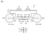
- the operating device 10 includes a first grip 41A, a first vibrating body 46A, a second grip 41B, and a second vibrating body 46B.
- the first grip 41A and the second grip 41B are both connected to the housing body 20. This connection structure will be described later.
- the first grip 41A includes a first grip housing 42A and a first protruding portion 43A.
- the first grip housing 42A is generally cylindrical and extends along the second axis Y. Therefore, the first grip housing 42A has a cavity inside.
- the first grip housing 42A is located on the third negative direction Z2 side, the first negative direction X2 side, and the second negative direction Y2 side of the center of gravity 24 of the housing body 20.
- this "center of gravity” refers to the geometric center of gravity with respect to the outer surface when it is assumed that the outer surface of the housing body 20 does not have a through hole for inserting the operating unit 30, etc.
- the first protrusion 43A is in the shape of a plate that is approximately a right triangle. One side of the triangle of the first protrusion 43A is connected to the surface of the first grip housing 42A on the first positive direction X1 side. The first protrusion 43A protrudes from that surface toward the first positive direction X1 side. The first protrusion 43A is not in direct contact with the second surface 22 of the housing body 20. A gap exists between the first protrusion 43A and the second surface 22 of the housing body 20.
- the first protruding portion 43A also has a first through hole 44A and a screw hole 45A.
- the first through hole 44A is a hole that penetrates the first protruding portion 43A.
- the first through hole 44A is located near the apex of the first protruding portion 43A on the opposite side to the first grip housing 42A.
- the first protruding portion 43A is connected to the housing body 20 via the first through hole 44A. Details of this connection structure will be described later.
- the screw hole 45A penetrates the first protruding portion 43A.
- the screw hole 45A is located on the first negative direction X2 side of the first through hole 44A.
- the first grip housing 42A houses the first vibrating body 46A inside.
- the first vibrating body 46A includes a voice coil motor, a weight corresponding to each voice coil motor, and a cubic case that houses them.
- the weight vibrates due to the force generated when a current flows through the coil of the voice coil motor.
- the case vibrates due to the vibration of the weight. Therefore, by controlling the current flowing through the coil of the voice coil motor, the first vibrating body 46A vibrates in a direction along an axis perpendicular to the surface of the case. Specifically, the first vibrating body 46A vibrates in a direction along the second axis Y.
- the vibration of the first vibrating body 46A is transmitted to the first grip 41A via the case of the first vibrating body 46A.
- the second grip 41B includes a second grip housing 42B and a second protruding portion 43B.
- the second grip housing 42B is generally cylindrical and extends along the second axis Y.
- the second grip housing 42B has a cavity therein.
- the second grip housing 42B is located in the third negative direction Z2, on the first positive direction X1 side, and on the second negative direction Y2 side with respect to the center of gravity 24 of the housing body 20.
- the second protrusion 43B is in the shape of a plate that is approximately a right triangle. One side of the triangle of the second protrusion 43B is connected to the surface of the second grip housing 42B on the first negative direction X2 side. The second protrusion 43B protrudes from that surface toward the first negative direction X2 side. The second protrusion 43B is not in direct contact with the second surface 22 of the housing body 20. A gap exists between the second protrusion 43B and the second surface 22 of the housing body 20.
- the second protruding portion 43B also has a second through hole 44B and a screw hole 45B.
- the second through hole 44B is a hole that penetrates the second protruding portion 43B.
- the second through hole 44B is located near the apex of the second protruding portion 43B on the opposite side to the second grip housing 42B.
- the second protruding portion 43B is connected to the housing body 20 via the second through hole 44B. The details of this connection structure will be described later.
- the screw hole 45B penetrates the second protruding portion 43B.
- the screw hole 45B is located on the first positive direction X1 side of the second through hole 44B.
- the second grip housing 42B houses the second vibrating body 46B inside.
- the second vibrating body 46B has the same configuration as the first vibrating body 46A. Therefore, the second vibrating body 46B is equipped with a voice coil motor, a weight corresponding to each voice coil motor, and a cubic case that houses these. The vibration of the second vibrating body 46B is transmitted to the second grip 41B via the case of the second vibrating body 46B.
- the second grip 41B includes the center of gravity 24 of the housing body 20 and has a symmetrical structure to the first grip 41A with respect to an imaginary plane perpendicular to the first axis X. Furthermore, the second vibrating body 46B includes the center of gravity 24 of the housing body 20 and has a symmetrical structure to the first vibrating body 46A with respect to an imaginary plane perpendicular to the first axis X. Note that this "symmetrical" allows for minor deviations due to manufacturing errors, etc.
- the operating device 10 includes a wiring 80 and a control device 90.
- the wiring 80 is inserted into the housing body 20.
- One end of the wiring 80 is connected to the control device 90.
- the other end of the wiring 80 is connected to an external device (not shown).
- the wiring 80 can supply power from the external device to the control device 90, the first vibrating body 46A, and the second vibrating body 46B.
- the control device 90 is stored inside the housing body 20.
- the control device 90 inputs a signal corresponding to the operation to an external device via the wiring 80.
- the control device 90 also controls the vibration of the first vibrating body 46A and the second vibrating body 46B.
- the control device 90 can generate a force sense in each vibrating body by controlling the vibration pattern of each vibrating body.
- the control device 90 generates a force sense in the second positive direction Y1 or the second negative direction Y2 by controlling the vibration pattern of each vibrating body in the direction along the second axis Y.
- a force sense in the clockwise or counterclockwise rotation direction is generated by individually controlling the vibration patterns of the first vibrating body 46A and the second vibrating body 46B.
- a force sense is a sensation of a resistance force received from an object.
- the control device 90 may be configured as a circuit including one or more processors that execute various processes according to a computer program (software).
- the control device 90 may also be configured as a circuit including one or more dedicated hardware circuits, such as an application specific integrated circuit (ASIC), that execute at least some of the various processes, or a combination thereof.
- the processor includes a CPU and memory such as RAM and ROM.
- the memory stores program code or instructions configured to cause the CPU to execute processes.
- Memory i.e., computer readable medium, includes any available medium that can be accessed by a general-purpose or dedicated computer.
- the operating device 10 includes a connection member 50, a first connecting portion 61A, and a second connecting portion 61B.
- the connection member 50 is a rectangular plate that is long along the first axis X.
- the connection member 50 has a total of two screw holes 51, one at each end of the connection member 50.
- the connection member 50 overlaps the first overhanging portion 43A of the first grip 41A and the second overhanging portion 43B of the second grip 41B on the third negative direction Z2 side.
- the connection member 50 straddles both the first overhanging portion 43A and the second overhanging portion 43B.
- the first connecting portion 61A is a screw.
- the first connecting portion 61A is inserted into one of the screw holes 51 of the connection member 50 and the first through hole 44A of the first protruding portion 43A.
- the tip of the first connecting portion 61A reaches the housing body 20.
- the first connecting portion 61A connects the connection member 50, the first protruding portion 43A, and the housing body 20.
- the outer diameter of the shaft portion of the first connecting portion 61A is smaller than the inner diameter of the first through hole 44A. That is, there is a slight gap between the outer peripheral surface of the first connecting portion 61A and the inner peripheral surface of the first through hole 44A.
- the second connecting portion 61B is a screw.
- the second connecting portion 61B is inserted into one of the screw holes 51 of the connection member 50 and the second through hole 44B of the second protruding portion 43B.
- the tip of the second connecting portion 61B reaches the housing body 20.
- the second connecting portion 61B connects the connection member 50, the second protruding portion 43B, and the housing body 20.
- the outer diameter of the shaft portion of the second connecting portion 61B is smaller than the inner diameter of the second through hole 44B. That is, there is a slight gap between the outer peripheral surface of the second connecting portion 61B and the inner peripheral surface of the second through hole 44B.
- the operating device 10 includes a first damper 71A and a second damper 71B.
- the first damper 71A is interposed between the housing body 20 and the first grip 41A. More specifically, the first damper 71A is fixed to the first protruding portion 43A.
- the first damper 71A has a first intermediate cushioning material 72A, a first back cushioning material 73A, and a first screw 74A.
- the first intermediate cushioning material 72A is located on the surface of the first protruding portion 43A on the housing body 20 side in the direction along the third axis Z. That is, the first intermediate cushioning material 72A is located between the first protruding portion 43A and the housing body 20.
- the first intermediate cushioning material 72A also blocks the screw hole 45A of the first protruding portion 43A from the side of the third positive direction Z1.
- the first intermediate cushioning material 72A is approximately circular in plan view.
- the thickness of the first intermediate cushioning material 72A is approximately the same as the distance between the first protruding portion 43A and the housing body 20.
- the first intermediate cushioning material 72A is fixed to the housing body 20 with an adhesive or the like.
- the material of the first intermediate cushioning material 72A is a gel-like material such as silicone.
- the first back side cushioning material 73A is located on the surface on the third negative direction Z2 side of the first protrusion 43A.
- the first back side cushioning material 73A also surrounds the opening on the third negative direction Z2 side of the screw hole 45A of the first protrusion 43A.
- the first screw 74A of the first damper 71A is inserted into the screw hole 45A while penetrating the first back side cushioning material 73A.
- the first screw 74A also reaches the first intermediate cushioning material 72A. Therefore, the first screw 74A fixes the first intermediate cushioning material 72A and the first back side cushioning material 73A to the first protrusion 43A.
- the material of the first back side cushioning material 73A is a gel-like material such as silicone.
- the elastic modulus of the first damper 71A is greater than the elastic modulus of the housing body 20 and the elastic modulus of the first grip 41A. More specifically, the elastic modulus of the first damper 71A is greater than the elastic modulus of the portion of the housing body 20 that contacts the first connecting portion 61A. Furthermore, the elastic modulus of the first damper 71A is greater than the elastic modulus of the inner circumferential surface of the first through hole 44A of the first protruding portion 43A. Therefore, the first damper 71A is softer than the housing body 20 and the first grip 41A.
- the second damper 71B is interposed between the housing body 20 and the second grip 41B. More specifically, the second damper 71B is fixed to the second protruding portion 43B.
- the second damper 71B has a second intermediate cushioning material 72B, a second back cushioning material 73B, and a second screw 74B.
- the second intermediate cushioning material 72B is located on the surface of the second protruding portion 43B on the housing body 20 side in the direction along the third axis Z. That is, the second intermediate cushioning material 72B is located between the second protruding portion 43B and the housing body 20.
- the second intermediate cushioning material 72B also blocks the screw hole 45B of the second protruding portion 43B from the third positive direction Z1 side.
- the second intermediate cushioning material 72B is approximately circular in plan view.
- the thickness of the second intermediate cushioning material 72B is approximately the same as the distance between the second protruding portion 43B and the housing body 20.
- the second intermediate cushioning material 72B is fixed to the housing body 20 with an adhesive or the like.
- the second intermediate cushioning material 72B is made of a gel-like material such as silicone.
- the second back side cushioning material 73B is located on the surface on the third negative direction Z2 side of the second protrusion 43B.
- the second back side cushioning material 73B also surrounds the opening on the third negative direction Z2 side of the screw hole 45B of the second protrusion 43B.
- the second screw 74B of the second damper 71B is inserted into the screw hole 45B while penetrating the second back side cushioning material 73B.
- the second screw 74B also reaches the second intermediate cushioning material 72B. Therefore, the second screw 74B fixes the second intermediate cushioning material 72B and the second back side cushioning material 73B to the second protrusion 43B.
- the material of the second back side cushioning material 73B is a gel-like material such as silicone.
- the elastic modulus of the second damper 71B is greater than the elastic modulus of the housing body 20 and the elastic modulus of the second grip 41B. More specifically, the elastic modulus of the second damper 71B is greater than the elastic modulus of the portion of the housing body 20 that contacts the second connecting portion 61B. Furthermore, the elastic modulus of the second damper 71B is greater than the elastic modulus of the inner circumferential surface of the second through hole 44B of the second protruding portion 43B. Therefore, the second damper 71B is softer than the housing body 20 and the second grip 41B.
- the first center of gravity GA of the first vibrating body 46A is located on the first negative direction X2 side and the second negative direction Y2 side with respect to the center of gravity 24 of the housing main body 20.
- the second center of gravity GB of the second vibrating body 46B is located on the first positive direction X1 side and the second negative direction Y2 side with respect to the operation unit 30.
- the center of gravity of the vibrating body refers to the center of gravity as the point of action of gravity on the mass of the vibrating body when the vibrating body is located at the vibration center.
- the direction in which the first grip 41A and the second grip 41B are aligned is the first direction.
- the first direction is the direction along the first axis X.
- the distance L1 in the first direction from the first connecting portion 61A to the first center of gravity GA of the first vibrating body 46A is at least one-third of the maximum dimension L2 in the first direction of the housing body 20.
- the distance in the first direction from the second connecting portion 61B to the second center of gravity GB of the second vibrating body 46B is at least one-third of the maximum dimension L2 in the first direction of the housing body 20.
- a line segment LG1 is assumed to connect the first connecting portion 61A and the first center of gravity GA of the first vibrating body 46A.
- the line segment LG1 is approximately parallel to the first axis X.
- the first vibrating body 46A vibrates in a direction intersecting the line segment LG1.
- the first vibrating body 46A vibrates in a direction along the second axis Y that is approximately perpendicular to the line segment LG1.
- a line segment LG2 is imagined connecting the second connecting portion 61B and the second center of gravity GB of the second vibrating body 46B.
- the line segment LG2 is approximately parallel to the first axis X.
- the second vibrating body 46B vibrates in a direction intersecting the line segment LG2.
- the second vibrating body 46B vibrates in a direction along the second axis Y that is approximately perpendicular to the line segment LG2.
- a line segment LG3 is imagined connecting the first center of gravity GA and the second center of gravity GB.
- the first connecting portion 61A and the second connecting portion 61B are present on the line segment LG3.
- both the first connecting portion 61A and the second connecting portion 61B are located near the midpoint of the line segment LG3.
- the respective connecting parts and the respective grips have the following relationship.
- the first connecting part 61A connects the first grip 41A to the housing body 20 so as to be relatively movable in any direction along the first axis X, the second axis Y, or the third axis Z.
- the second connecting part 61B connects the second grip 41B to the housing body 20 so as to be relatively movable in any direction along the first axis X, the second axis Y, or the third axis Z.
- each grip can move relative to the housing body 20. Therefore, when each vibrating body vibrates, the vibration of each grip is less likely to escape to the housing body 20. Therefore, each grip can be vibrated with the required intensity without using a large vibrating body.
- the operating device 10 is provided with dampers between the housing body 20 and each grip.
- the vibration of each grip is damped by elastic deformation of each damper. Therefore, even if each vibrating body vibrates, the housing body 20 is less likely to vibrate, and the vibration of each vibrating body is less likely to interfere with the operation of the input unit by the user.
- each vibrating body vibrates in a direction intersecting the line segment LG1 connecting the first connecting portion 61A and the first center of gravity GA of the first vibrating body 46A.
- the vibration of each vibrating body is less likely to be transmitted to each connecting portion. Therefore, each grip can be vibrated more efficiently.
- the second vibrating body 46B is located at a position symmetrical to the first vibrating body 46A with respect to a virtual plane including the geometric center of gravity 24 of the housing body 20. Since the operation device 10 is substantially symmetrical, it is easy to control the vibration pattern of each vibrating body.
- each connecting portion is located on the second surface 22 side of the housing body 20. Therefore, the user's operation of the operation unit 30 is less likely to be hindered. In addition, since it is easy to maintain a distance between the housing body 20 and each protrusion portion, the housing body 20 is less likely to come into contact with each grip. Therefore, it is easy to vibrate the vibrator.
- the first vibrating body 46A vibrates
- the first grip 41A vibrates along an arcuate trajectory centered on the first connecting portion 61A.
- the distance L1 in the first axis X direction from the first connecting portion 61A to the first center of gravity GA of the first vibrating body 46A is one-third or more of the maximum dimension L2 in the first axis X direction of the housing main body 20.
- the second connecting portion 61B, the second vibrating body 46B, and the second grip 41B is the distance L1 in the first axis X direction from the first connecting portion 61A to the first center of gravity GA of the first vibrating body 46A.
- the first connecting portion 61A and the second connecting portion 61B are located on the imaginary line segment LG3 that connects the first center of gravity GA and the second center of gravity GB. This makes it easy for the user to hold the operating device 10 even when each vibrating body vibrates. In addition, it is easy to design and control the vibration pattern of each vibrating body.
- the operating device 10 is not limited to the example of the present embodiment.
- the operating device 10 may be applied to any operating device that is operated by a user holding a grip, such as an automobile steering wheel or an operating device for medical equipment.
- the shape of the housing body 20 is not limited to a substantially rectangular parallelepiped shape. It may be changed as appropriate depending on the application, etc.
- the configuration of the operation unit 30 is not limited to that of the above embodiment.
- the operation unit 30 may be a touch panel that receives input from the user.
- the operating device 10 may include at least one grip.
- the size, shape, and other configurations of the grip are not limited to those in the above embodiment.
- the shape of the overhanging portion is not limited to the example of the above embodiment.
- the first overhanging portion 43A may be an L-shape that extends from the surface of the first grip 41A on the third positive direction Z1 side in the third positive direction Z1 side and bends toward the first positive direction X1 side midway.
- the positions and sizes of the through holes and screw holes of the overhanging portion may be changed as appropriate. The same applies to the second grip 41B.
- the operating device 10 may include at least one vibrating body.
- the operating device 10 may include three or more vibrating bodies.
- the first grip 41A may store two first vibrating bodies 46A at both ends of the first grip housing 42A.
- the second grip 41B may store two second vibrating bodies 46B at both ends of the second grip housing 42B.
- Each grip does not have to completely cover the vibrator. In other words, even if a part of the case of the vibrator is exposed, it is sufficient if it is housed inside the grip.
- the configuration of the vibrator is not limited to the example of the above embodiment.
- the vibrator may simply vibrate and not provide a haptic sensation.
- the vibrator may also be capable of vibrating in the first axis X direction, the third axis Z direction, etc., in addition to the second axis Y direction.
- the second vibrating body 46B does not have to be located symmetrically to the first vibrating body 46A with respect to a virtual plane including the geometric center of gravity of the housing body 20.
- the positional relationship between the first vibrating body 46A and the second vibrating body 46B may be set appropriately depending on the overall shape of the operating device 10, the type of vibration to be presented to the user, etc.
- the first grip housing 42A stores two first vibrators 46A. These two first vibrators 46A are located at positions separated in the direction along the second axis Y.
- the second grip housing 42B stores two second vibrators 46B. These two second vibrators 46B are located at positions separated in the direction along the second axis Y.
- the function, configuration, and the like of the wiring 80 are not limited to the example of the above embodiment.
- the housing body 20 may have a terminal to which a wiring can be connected from the outside, and the operation device 10 may have a rechargeable battery inside the housing body 20.
- the operation device 10 may not be provided with the wiring 80.
- control device 90 does not need to input a signal through the wiring 80.
- control device 90 may be equipped with a module capable of wireless communication, and may transmit a signal corresponding to an input by the user to the operation unit 30 via wireless communication.
- operation device 10 does not need to be equipped with the control device 90.
- the vibration pattern of the vibrator controlled by the control device 90 is not limited to the example of the above embodiment. It can be changed as appropriate depending on the number, shape, position, size, material, function, and other elements of the vibrator, connecting parts, grips, and other components.
- the vibration direction of each vibrator may be the same or different. If the vibration direction of each vibrator is different, it is possible to present the user with force sensations in various directions. It is also possible to present the user with a force sensation as if the grip were rotating.
- the connecting portion does not have to be located on the surface facing the third negative direction Z2 of the outer surface of the housing body 20.
- the number, shape, position, size, material, function, and other elements of the connecting portions are not limited to the example of the above embodiment.
- the outer diameter of the shaft of the first connecting part 61A does not have to be smaller than the inner diameter of the first through hole 44A. That is, there may be no gap between the outer peripheral surface of the first connecting part 61A and the inner peripheral surface of the first through hole 44A. Even if the first connecting part 61A and the first through hole 44A are in contact, the first grip housing 42A can move relative to the housing body 20 along the central axis of the first connecting part 61A. Therefore, the first grip 41A is more likely to vibrate than when the housing body 20 and the first grip 41A are directly connected. That is, the effect described in (1) can be obtained. The same applies to the second connecting part 61B and the second through hole 44B.
- the operating device 10 includes a first rotating shaft 101A and a second rotating shaft 101B as a connecting portion.
- the operating device 10 also includes a first buffer material 102A and a second buffer material 102B as a damper.
- One end of the first rotating shaft 101A is connected to a surface of the outer surface of the first grip housing 42A facing the first positive direction X1.
- a part of the first rotating shaft 101A, including the other end, is inserted into the housing body 20.
- the first rotating shaft 101A is rotatably supported by the housing body 20.
- the first grip 41A can rotate relative to the housing body 20 together with the first rotating shaft 101A around the central axis of the first rotating shaft 101A.
- the first buffer material 102A is interposed between the outer surface of the first grip housing 42A and the outer surface of the housing body 20.
- the material of the first buffer material 102A is a gel-like material such as silicon.
- One end of the second rotating shaft 101B is connected to a surface of the outer surface of the first grip housing 42A facing the first negative direction X2. A part of the second rotating shaft 101B, including the other end, is inserted into the housing body 20.
- the second rotating shaft 101B is rotatably supported by the housing body 20.
- the second grip 41B can rotate relative to the housing body 20 together with the second rotating shaft 101B around the central axis of the second rotating shaft 101B.
- the second cushioning material 102B is interposed between the outer surface of the second grip housing 42B and the outer surface of the housing body 20.
- the material of the second cushioning material 102B is a gel-like material such as silicone.
- each grip does not necessarily need to be able to move three-dimensionally relative to the housing body 20, but may be able to move two-dimensionally and linearly relative to the housing body 20. Furthermore, a small range of relative movement for each grip, such as a few millimeters, is sufficient.
- the operating device 10 does not have to include a damper.
- the effect described in (1) can be obtained even if the operating device 10 does not include a damper.
- the configuration of the damper is not limited to the example of the above embodiment.
- the damper may be configured with a spring or the like having a greater elastic modulus than the housing body 20 and the grip.
- the number, position, size, and other elements of the dampers are not limited to the example of the above embodiment. As long as the damper is interposed between the grip housing and the housing body 20, the effect of damping the vibration transmitted to the housing body 20 by the damper can be obtained.
- the materials of the first intermediate cushioning material 72A and the first rear cushioning material 73A are not limited to those in the above embodiment. For example, they may be vibration-proof rubber or urethane.
- the damper may also function as a connecting portion.
- the connection member 50, the first connecting portion 61A, and the second connecting portion 61B may be omitted.
- the first damper 71A connects the first grip housing 42A and the housing main body 20.
- the first damper 71A is elastically deformed, so that the first grip 41A can move relative to the housing main body 20.
- the distance L1 in the first direction from the first connecting portion 61A to the first center of gravity GA of the first vibrating body 46A may be less than one-third of the maximum dimension L2 in the first direction of the operating device 10. Even if the distance L1 is short, the effect of (1) can be obtained because the housing body 20 and the grip are connected via a connecting portion. The same applies to the second connecting portion 61B, the second vibrating body 46B, and the second center of gravity GB.
- the first connecting portion 61A and the second connecting portion 61B do not have to be present on the line segment LG3 connecting the first center of gravity GA and the second center of gravity GB. Furthermore, the first connecting portion 61A and the second connecting portion 61B do not have to be located near the midpoint of the line segment LG3. The effect described in (1) can be obtained even if the positional relationship between the connecting portions and the center of gravity of the vibrating body varies.
- the first rotating shaft 101A and the second rotating shaft 101B serving as a connecting portion are located on a straight line CL passing through the center point of the dimension of the first grip housing 42A in the second axis Y direction and the center point of the dimension of the second grip housing 42B in the direction along the second axis Y. Even in this case, the effect is obtained that the user can easily grip the operating device 10 when each vibrating body vibrates.
- an operation unit for receiving input from a user A housing body supporting the operation unit; One or more vibrating bodies capable of generating vibrations; One or more grips housing the vibration body; One or more connecting parts that connect the grip to the housing body so as to be relatively movable;
- An operating device comprising:
- a damper is provided between the housing body and the grip;
- the vibrating body includes a first vibrating body and a second vibrating body
- the grip includes a first grip that houses the first vibrator and a second grip that houses the second vibrator
- the connecting portion includes a first connecting portion that connects the first grip and the housing body, and a second connecting portion that connects the second grip and the housing body
- Operation device 20 Housing body 30: Operation section 41A: First grip 41B: Second grip 50: Connection member 61A: First coupling section 61B: Second coupling section 71A: First damper 71B: Second damper 80: Wiring 90: Control device
Landscapes
- Engineering & Computer Science (AREA)
- Multimedia (AREA)
- General Engineering & Computer Science (AREA)
- Theoretical Computer Science (AREA)
- Human Computer Interaction (AREA)
- Physics & Mathematics (AREA)
- General Physics & Mathematics (AREA)
- Microelectronics & Electronic Packaging (AREA)
- User Interface Of Digital Computer (AREA)
- Position Input By Displaying (AREA)
Priority Applications (4)
| Application Number | Priority Date | Filing Date | Title |
|---|---|---|---|
| JP2025508231A JPWO2024195388A1 (https=) | 2023-03-17 | 2024-02-16 | |
| EP24774533.4A EP4645036A1 (en) | 2023-03-17 | 2024-02-16 | Operation device |
| CN202480009331.3A CN120604194A (zh) | 2023-03-17 | 2024-02-16 | 操作装置 |
| US19/262,372 US20250335037A1 (en) | 2023-03-17 | 2025-07-08 | Operating device |
Applications Claiming Priority (2)
| Application Number | Priority Date | Filing Date | Title |
|---|---|---|---|
| JP2023043153 | 2023-03-17 | ||
| JP2023-043153 | 2023-03-17 |
Related Child Applications (1)
| Application Number | Title | Priority Date | Filing Date |
|---|---|---|---|
| US19/262,372 Continuation US20250335037A1 (en) | 2023-03-17 | 2025-07-08 | Operating device |
Publications (1)
| Publication Number | Publication Date |
|---|---|
| WO2024195388A1 true WO2024195388A1 (ja) | 2024-09-26 |
Family
ID=92841339
Family Applications (1)
| Application Number | Title | Priority Date | Filing Date |
|---|---|---|---|
| PCT/JP2024/005587 Ceased WO2024195388A1 (ja) | 2023-03-17 | 2024-02-16 | 操作装置 |
Country Status (5)
| Country | Link |
|---|---|
| US (1) | US20250335037A1 (https=) |
| EP (1) | EP4645036A1 (https=) |
| JP (1) | JPWO2024195388A1 (https=) |
| CN (1) | CN120604194A (https=) |
| WO (1) | WO2024195388A1 (https=) |
Citations (5)
| Publication number | Priority date | Publication date | Assignee | Title |
|---|---|---|---|---|
| JP2002224444A (ja) * | 2001-01-31 | 2002-08-13 | Konami Co Ltd | ゲームコントローラ |
| JP2011183374A (ja) * | 2010-02-10 | 2011-09-22 | Sanyo Electric Co Ltd | 電子機器 |
| JP2017037371A (ja) | 2015-08-06 | 2017-02-16 | 株式会社ソニー・インタラクティブエンタテインメント | 操作装置 |
| JP2017221427A (ja) * | 2016-06-15 | 2017-12-21 | 任天堂株式会社 | ゲームシステム、方法、およびゲームプログラム |
| WO2019043787A1 (ja) * | 2017-08-29 | 2019-03-07 | 株式会社ソニー・インタラクティブエンタテインメント | 振動制御装置 |
Family Cites Families (1)
| Publication number | Priority date | Publication date | Assignee | Title |
|---|---|---|---|---|
| JP6074534B2 (ja) * | 2015-06-12 | 2017-02-01 | 任天堂株式会社 | ゲームコントローラ |
-
2024
- 2024-02-16 WO PCT/JP2024/005587 patent/WO2024195388A1/ja not_active Ceased
- 2024-02-16 CN CN202480009331.3A patent/CN120604194A/zh active Pending
- 2024-02-16 JP JP2025508231A patent/JPWO2024195388A1/ja active Pending
- 2024-02-16 EP EP24774533.4A patent/EP4645036A1/en active Pending
-
2025
- 2025-07-08 US US19/262,372 patent/US20250335037A1/en active Pending
Patent Citations (5)
| Publication number | Priority date | Publication date | Assignee | Title |
|---|---|---|---|---|
| JP2002224444A (ja) * | 2001-01-31 | 2002-08-13 | Konami Co Ltd | ゲームコントローラ |
| JP2011183374A (ja) * | 2010-02-10 | 2011-09-22 | Sanyo Electric Co Ltd | 電子機器 |
| JP2017037371A (ja) | 2015-08-06 | 2017-02-16 | 株式会社ソニー・インタラクティブエンタテインメント | 操作装置 |
| JP2017221427A (ja) * | 2016-06-15 | 2017-12-21 | 任天堂株式会社 | ゲームシステム、方法、およびゲームプログラム |
| WO2019043787A1 (ja) * | 2017-08-29 | 2019-03-07 | 株式会社ソニー・インタラクティブエンタテインメント | 振動制御装置 |
Non-Patent Citations (1)
| Title |
|---|
| See also references of EP4645036A1 |
Also Published As
| Publication number | Publication date |
|---|---|
| CN120604194A (zh) | 2025-09-05 |
| EP4645036A1 (en) | 2025-11-05 |
| US20250335037A1 (en) | 2025-10-30 |
| JPWO2024195388A1 (https=) | 2024-09-26 |
Similar Documents
| Publication | Publication Date | Title |
|---|---|---|
| US9053618B2 (en) | Portable terminal having haptic module with a hinge part supporting a touch pad | |
| CN109923504B (zh) | 带触摸面板的显示装置 | |
| CN112018992B (zh) | 致动器及触觉设备 | |
| JP2020067869A (ja) | タッチパッドモジュール | |
| US8324786B2 (en) | Piezoelectric actuator module | |
| JP2023065769A (ja) | アクチュエータ | |
| JP2018073021A (ja) | タッチパネル付き表示装置 | |
| CN109565233A (zh) | 振动产生装置 | |
| WO2024195388A1 (ja) | 操作装置 | |
| US11886640B2 (en) | Operation device | |
| JP7704223B2 (ja) | 力覚提示装置 | |
| JP7386030B2 (ja) | アクチュエータ | |
| CN104205278B (zh) | 操作设备 | |
| KR20100135008A (ko) | 터치 입력식 전자기기 | |
| JP2021030188A (ja) | 電子機器 | |
| JP7631641B2 (ja) | ペン型指示具 | |
| JP7402006B2 (ja) | アクチュエータ | |
| JP7722471B2 (ja) | ハプティクス装置 | |
| JPWO2018146934A1 (ja) | 力覚発生装置 | |
| KR101673790B1 (ko) | 3차원 왜곡 센서와 3차원 진동자를 이용한 촉각 피드백 컨트롤러 | |
| EP3575927A1 (en) | Unit and tactile sensation providing apparatus | |
| WO2020195813A1 (ja) | 斜め方向の牽引錯覚を発生させる電子機器 | |
| JP7266046B2 (ja) | 入力装置 | |
| US20190012030A1 (en) | Input apparatus and input system | |
| JP7421576B2 (ja) | 入力装置、及び、入力モジュール |
Legal Events
| Date | Code | Title | Description |
|---|---|---|---|
| 121 | Ep: the epo has been informed by wipo that ep was designated in this application |
Ref document number: 24774533 Country of ref document: EP Kind code of ref document: A1 |
|
| ENP | Entry into the national phase |
Ref document number: 2025508231 Country of ref document: JP Kind code of ref document: A |
|
| WWE | Wipo information: entry into national phase |
Ref document number: 2025508231 Country of ref document: JP |
|
| WWE | Wipo information: entry into national phase |
Ref document number: 202480009331.3 Country of ref document: CN |
|
| WWE | Wipo information: entry into national phase |
Ref document number: 2024774533 Country of ref document: EP |
|
| ENP | Entry into the national phase |
Ref document number: 2024774533 Country of ref document: EP Effective date: 20250728 |
|
| ENP | Entry into the national phase |
Ref document number: 2024774533 Country of ref document: EP Effective date: 20250728 |
|
| WWP | Wipo information: published in national office |
Ref document number: 202480009331.3 Country of ref document: CN |
|
| NENP | Non-entry into the national phase |
Ref country code: DE |
|
| WWP | Wipo information: published in national office |
Ref document number: 2024774533 Country of ref document: EP |