WO2024195287A1 - ガスタービン - Google Patents
ガスタービン Download PDFInfo
- Publication number
- WO2024195287A1 WO2024195287A1 PCT/JP2024/002163 JP2024002163W WO2024195287A1 WO 2024195287 A1 WO2024195287 A1 WO 2024195287A1 JP 2024002163 W JP2024002163 W JP 2024002163W WO 2024195287 A1 WO2024195287 A1 WO 2024195287A1
- Authority
- WO
- WIPO (PCT)
- Prior art keywords
- steam
- fuel
- gas turbine
- combustor
- injection
- Prior art date
- Legal status (The legal status is an assumption and is not a legal conclusion. Google has not performed a legal analysis and makes no representation as to the accuracy of the status listed.)
- Ceased
Links
Images



Classifications
-
- F—MECHANICAL ENGINEERING; LIGHTING; HEATING; WEAPONS; BLASTING
- F02—COMBUSTION ENGINES; HOT-GAS OR COMBUSTION-PRODUCT ENGINE PLANTS
- F02C—GAS-TURBINE PLANTS; AIR INTAKES FOR JET-PROPULSION PLANTS; CONTROLLING FUEL SUPPLY IN AIR-BREATHING JET-PROPULSION PLANTS
- F02C3/00—Gas-turbine plants characterised by the use of combustion products as the working fluid
- F02C3/20—Gas-turbine plants characterised by the use of combustion products as the working fluid using a special fuel, oxidant, or dilution fluid to generate the combustion products
- F02C3/30—Adding water, steam or other fluids for influencing combustion, e.g. to obtain cleaner exhaust gases
-
- F—MECHANICAL ENGINEERING; LIGHTING; HEATING; WEAPONS; BLASTING
- F02—COMBUSTION ENGINES; HOT-GAS OR COMBUSTION-PRODUCT ENGINE PLANTS
- F02C—GAS-TURBINE PLANTS; AIR INTAKES FOR JET-PROPULSION PLANTS; CONTROLLING FUEL SUPPLY IN AIR-BREATHING JET-PROPULSION PLANTS
- F02C7/00—Features, components parts, details or accessories, not provided for in, or of interest apart form groups F02C1/00 - F02C6/00; Air intakes for jet-propulsion plants
- F02C7/22—Fuel supply systems
-
- F—MECHANICAL ENGINEERING; LIGHTING; HEATING; WEAPONS; BLASTING
- F02—COMBUSTION ENGINES; HOT-GAS OR COMBUSTION-PRODUCT ENGINE PLANTS
- F02C—GAS-TURBINE PLANTS; AIR INTAKES FOR JET-PROPULSION PLANTS; CONTROLLING FUEL SUPPLY IN AIR-BREATHING JET-PROPULSION PLANTS
- F02C9/00—Controlling gas-turbine plants; Controlling fuel supply in air- breathing jet-propulsion plants
-
- F—MECHANICAL ENGINEERING; LIGHTING; HEATING; WEAPONS; BLASTING
- F02—COMBUSTION ENGINES; HOT-GAS OR COMBUSTION-PRODUCT ENGINE PLANTS
- F02C—GAS-TURBINE PLANTS; AIR INTAKES FOR JET-PROPULSION PLANTS; CONTROLLING FUEL SUPPLY IN AIR-BREATHING JET-PROPULSION PLANTS
- F02C9/00—Controlling gas-turbine plants; Controlling fuel supply in air- breathing jet-propulsion plants
- F02C9/26—Control of fuel supply
- F02C9/28—Regulating systems responsive to plant or ambient parameters, e.g. temperature, pressure, rotor speed
-
- F—MECHANICAL ENGINEERING; LIGHTING; HEATING; WEAPONS; BLASTING
- F02—COMBUSTION ENGINES; HOT-GAS OR COMBUSTION-PRODUCT ENGINE PLANTS
- F02C—GAS-TURBINE PLANTS; AIR INTAKES FOR JET-PROPULSION PLANTS; CONTROLLING FUEL SUPPLY IN AIR-BREATHING JET-PROPULSION PLANTS
- F02C9/00—Controlling gas-turbine plants; Controlling fuel supply in air- breathing jet-propulsion plants
- F02C9/26—Control of fuel supply
- F02C9/40—Control of fuel supply specially adapted to the use of a special fuel or a plurality of fuels
Definitions
- At least one embodiment of the present disclosure aims to increase the hydrogen co-firing rate while suppressing flame backflow and other problems in a gas turbine.
- a gas turbine includes: A gas turbine including a combustor capable of co-firing a first fuel and a hydrogen fuel having a combustion speed faster than that of the first fuel, A mixed combustion ratio acquisition unit that acquires information indicating a magnitude of the mixed combustion ratio of the hydrogen fuel; a steam injection control unit that controls an injection amount of steam to be injected into the compressed air flowing through a flow path for supplying the air compressed by a compressor to the combustor; having The steam injection control unit controls an injection amount of the steam based on the mixed-combustion ratio of the hydrogen fuel acquired by the mixed-combustion ratio acquisition unit.
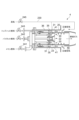
- FIG. 1 illustrates an example configuration of a gas turbine according to some embodiments.
- FIG. 2 is a diagram illustrating an example of the configuration of a combustor of the gas turbine illustrated in FIG. 1 .
- FIG. 2 is a functional block diagram of a control device according to some embodiments.
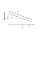
- 1 is a graph showing the relationship between the ratio of the steam injection amount to the fuel flow rate and the laminar burning velocity of the fuel.
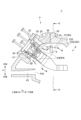
- FIG. 1 is a schematic diagram illustrating a combustor and turbine inlet section of a gas turbine according to some embodiments.
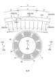
- FIG. 6 is a schematic cross-sectional view of a turbine in a gas turbine according to some embodiments taken along line VI-VI in FIG. 5 . 7 is a cross-sectional view taken along the line VII-VII of FIG. 5.
- expressions indicating that things are in an equal state such as “identical,””equal,” and “homogeneous,” not only indicate a state of strict equality, but also indicate a state in which there is a tolerance or a difference to the extent that the same function is obtained.
- expressions describing shapes such as a rectangular shape or a cylindrical shape do not only refer to rectangular shapes, cylindrical shapes, etc. in the strict geometric sense, but also refer to shapes that include uneven portions, chamfered portions, etc., to the extent that the same effect is obtained.
- the expressions “comprise,””include,””have,””includes,” or “have” of one element are not exclusive expressions excluding the presence of other elements.
- FIG. 1 is a diagram showing an example of the configuration of a gas turbine according to some embodiments.
- FIG. 2 is a diagram showing an example of the configuration of a combustor of the gas turbine shown in FIG. 1.
- a gas turbine 1 includes a compressor 2 that generates compressed air, a number of combustors 4 that burn fuel using the compressed air supplied from the compressor 2, and a turbine 6 that has a rotating shaft 5 in common with the compressor 2 and is driven by the combustion gas generated in the multiple combustors 4.
- a generator 8 is connected to the rotating shaft 5.
- the amount of intake air of the compressor 2 can be adjusted by changing the opening degree of an inlet guide vane (IGV) 3A provided at the inlet of the compressor 2 using an actuator 3B.
- the rotational speed of the rotating shaft 5 can be detected by a rotational speed sensor 9.
- each of the multiple combustors 4 has a pilot burner 22 disposed at the center of a cylindrical inner tube 20, and a plurality of (e.g., eight) main burners 30 disposed at equal pitch in the circumferential direction of the inner tube 20 so as to surround the pilot burner 22.
- the multiple combustors 4 are attached at intervals in the circumferential direction around the rotation axis 5 to a combustor casing 60 (see FIGS. 5 and 6 ), which will be described later and which defines the casing space 40.
- the pilot burner 22 is equipped with a pilot nozzle 23 that supplies pilot fuel.
- the main burner 30 is equipped with a main nozzle 31 that supplies the main fuel.
- top hat nozzles 35 that supply top hat fuel are provided upstream of the pilot burner 22 and main burner 30 in the flow of compressed air.
- the top hat nozzles 35 are disposed in the annular space 41 between the inner cylinder 20 and the outer cylinder 36 that surrounds the inner cylinder 20.
- the fuel flow rate of the pilot nozzle 23, main nozzle 31, and top hat nozzle 35 is independently adjusted by flow control valves (241, 242, 243) described below.
- the compressed air generated by the compressor 2 is supplied to the vehicle interior space 40, and is further supplied from the vehicle interior space 40 to the main burner 30 and pilot burner 22 via the annular space 41 between the inner cylinder 20 and the outer cylinder 36.
- the combustor 4 is configured to be able to use, for example, natural gas as the first fuel F1 as in a conventional combustor, and hydrogen as the second fuel F2 as the fuel F.
- natural gas as the fuel F will be referred to as natural gas fuel FN, or simply as natural gas.
- hydrogen as the fuel F will be referred to as hydrogen fuel FH, or simply as hydrogen.
- natural gas fuel FN, hydrogen fuel FH, and mixed fuel FM of natural gas fuel FN and hydrogen fuel FH will be referred to as fuel F when there is no need to particularly distinguish between them or when these fuels are referred to collectively.
- BFG Blast Furnace Gas
- a gas turbine 1 includes a supply system 200 for fuel F shown in Fig. 1.
- the supply system 200 for fuel F shown in Fig. 1 includes a first supply line 211 for supplying natural gas fuel FN to the main nozzle 31, a second supply line 212 for supplying natural gas fuel FN to the pilot nozzle 23, a third supply line 213 for supplying natural gas fuel FN to the top hat nozzle 35, and a hydrogen supply line 220 for supplying hydrogen fuel FH to the main nozzle 31, the pilot nozzle 23, and the top hat nozzle 35.
- Natural gas fuel FN is supplied from a source 201 of natural gas fuel FN via a natural gas supply line 210 .
- the natural gas supply line 210 is provided with a flow rate control valve 240 for adjusting the flow rate of the natural gas fuel FN flowing through the natural gas supply line 210 .
- the first supply line 211 , the second supply line 212 , and the third supply line 213 branch off from the natural gas supply line 210 downstream of the flow rate control valve 240 .
- the first supply line 211 is provided with a flow rate adjustment valve 241 for adjusting the amount of fuel F supplied to the main nozzle 31 .
- the second supply line 212 is provided with a flow rate adjustment valve 242 for adjusting the amount of fuel F supplied to the pilot nozzle 23 .
- the third supply line 213 is provided with a flow rate adjustment valve 243 for adjusting the amount of fuel F supplied to the top hat nozzle 35.
- Hydrogen fuel FH is supplied from a source 202 of hydrogen fuel FH via a hydrogen supply line 220 .
- the hydrogen supply line 220 is provided with a flow rate control valve 244 for adjusting the amount of hydrogen fuel FH supplied to the main nozzles 31, the pilot nozzle 23, and the top hat nozzle 35.
- the downstream end of the hydrogen supply line 220 is connected to the natural gas supply line 210 at a junction 215 upstream of the branching points of the natural gas supply line 210 to the first supply line 211, the second supply line 212, and the third supply line 213. That is, the flow rate control valve 244 is a flow rate control valve for controlling the amount of hydrogen fuel FH added to the natural gas fuel FN flowing through the natural gas supply line 210 .
- the natural gas supply line 210 is provided with a flow rate sensor 251 for detecting the flow rate of the natural gas fuel FN flowing through the natural gas supply line 210 .
- the hydrogen supply line 220 is provided with a flow rate sensor 252 for detecting the flow rate of the hydrogen fuel FH flowing through the hydrogen supply line 220 .
- each flow rate control valve 240, 244 can be adjusted to adjust the hydrogen mixed combustion ratio (calorie ratio), which is the ratio of hydrogen fuel FH in the fuel F injected in the main nozzle 31, the pilot nozzle 23, and the top hat nozzle 35.
- calorie ratio the ratio of hydrogen fuel FH in the fuel F injected in the main nozzle 31, the pilot nozzle 23, and the top hat nozzle 35.
- the fuel flow rates of the main nozzle 31, the pilot nozzle 23, and the top hat nozzle 35 are independently adjusted by flow rate control valves 241, 242, and 243, respectively.
- Each of the flow rate control valves 240, 241, 242, 243, and 244 is controlled by a controller configured to control each of these flow rate control valves.
- this controller is realized by the control device 100 of the gas turbine 1, which will be described later.
- the gas turbine 1 In order to reduce carbon dioxide emissions, it is desirable to increase the hydrogen fuel FH co-firing ratio (hydrogen co-firing ratio).
- hydrogen fuel FH co-firing ratio hydrogen co-firing ratio
- the gas turbine 1 includes a steam supply line 230 for injecting steam into the compressed air supplied to the combustor 4.
- the steam S can be supplied from a supply source 205 of the steam S to the vehicle interior space 40 via a steam supply line 230.
- the steam S supplied from the steam supply line 230 may be supplied to the vehicle interior space 40, or may be supplied into an annular space 41 between the inner cylinder 20 and the outer cylinder 36 in the vicinity of the top hat nozzle 35, instead of or in addition to being supplied to the vehicle interior space 40, as indicated by a dashed line in FIG.
- the steam supply line 230 is provided with a steam flow rate control valve 245 for adjusting the supply amount of steam S (injection amount Qs of steam S) relative to the compressed air supplied to the combustor 4. As will be described later, the steam flow rate control valve 245 is controlled by a control device 100, which will be described later.
- the steam supply line 230 is provided with a flow rate sensor 253 for detecting the flow rate of the steam S flowing through the steam supply line 230 .
- a control device 100 includes a processor 101 that executes various arithmetic processes, and a memory 103 that non-temporarily or temporarily stores various data processed by the processor 101.
- the processor 101 is realized by a CPU, a GPU, an MPU, a DSP, various other arithmetic devices, or a combination of these.
- the memory 103 is realized by a ROM, a RAM, a flash memory, or a combination of these.
- Fig. 3 is a functional block diagram of a control device 100 according to some embodiments. Note that Fig. 3 illustrates only functional blocks related to the supply of steam S, which will be described later, and omits illustration of other functional blocks.
- the control device 100 includes a fuel flow rate acquisition unit 111, a mixed combustion ratio acquisition unit 113, a fuel-air ratio acquisition unit 115, a combustion temperature acquisition unit 117, and a steam injection control unit 119.
- the fuel flow rate acquisition unit 111, the mixed combustion ratio acquisition unit 113, the fuel-air ratio acquisition unit 115, the combustion temperature acquisition unit 117, and the steam injection control unit 119 are functional blocks that are realized by the processor 101 executing a program stored in the memory 103.
- the fuel flow rate acquisition unit 111 acquires the flow rate (fuel flow rate Qf) of the fuel F supplied to the combustor 4 from the flow rates of the natural gas fuel FN and the hydrogen fuel FH detected by the flow rate sensor 251 provided in the natural gas supply line 210 and the flow rate sensor 252 provided in the hydrogen supply line 220.
- the mixed combustion ratio acquisition unit 113 calculates and acquires the hydrogen mixed combustion ratio in the fuel F supplied to the combustor 4 from the flow rates of the natural gas fuel FN and the hydrogen fuel FH acquired by the fuel flow rate acquisition unit 111.
- the fuel-air ratio acquisition unit 115 calculates the fuel-air ratio F/A, which is the ratio of fuel F to the compressed air supplied to the combustor 4, based on the flow rates of the natural gas fuel FN and hydrogen fuel FH acquired by the fuel flow rate acquisition unit 111, and the air flow rate supplied to the combustor 4, which is calculated based on the rotational speed of the rotating shaft 5 detected by the rotational speed sensor 9 and the command value for the opening degree (IGV opening degree) of the inlet guide vane (IGV) 3A.
- the combustion temperature acquisition unit 117 calculates and acquires the combustion temperature in the turbine 6, specifically, the turbine inlet temperature T1T, based on the flow rates of the natural gas fuel FN and the hydrogen fuel FH acquired by the fuel flow rate acquisition unit 111, and the air flow rate supplied to the combustor 4 which is calculated based on the rotational speed of the rotating shaft 5 detected by the rotational speed sensor 9 and a command value for the opening degree (IGV opening degree) of the inlet guide vane (IGV) 3A.
- the combustion temperature acquisition unit 117 may acquire the turbine inlet temperature T1T by obtaining a measurement value of the turbine inlet temperature T1T measured by a temperature detection device (not shown).
- the steam injection control unit 119 controls the injection amount Qs of steam S to be injected into the compressed air supplied to the combustor 4 by controlling the opening degree of the steam flow control valve 245 based on the mixed-combustion ratio of the hydrogen fuel FH (hydrogen mixed-combustion ratio) acquired by the mixed-combustion ratio acquisition unit 113.
- the steam injection control unit 119 controls the injection amount Qs of steam S to be injected into the compressed air supplied to the combustor 4 by controlling the opening degree of the steam flow control valve 245 based on the mixed-combustion ratio of the hydrogen fuel FH (hydrogen mixed-combustion ratio) acquired by the mixed-combustion ratio acquisition unit 113.
- the steam injection control unit 119 controls the injection amount Qs of the steam S so that the injection amount Qs of the steam S increases as the hydrogen co-firing ratio increases. This makes it possible to effectively suppress flame backflow and the like, which is likely to occur as the hydrogen co-firing ratio increases.
- the graph line 71 shown in FIG. 4 is a graph line showing the relationship between the ratio S/F of the injection amount Qs of steam S to the fuel flow rate Qf and the laminar burning velocity Vb of fuel F when the turbine inlet temperature T1T is T1°C and the hydrogen mixing ratio is H1%, and the graph line 72 shown in FIG.
- the 4 is a graph line showing the relationship between the ratio S/F of the injection amount Qs of steam S to the fuel flow rate Qf and the laminar burning velocity Vb of fuel F when the turbine inlet temperature T1T is T2°C lower than T1°C and the hydrogen mixing ratio is H1%.
- the laminar burning velocity Vb1 is the laminar burning velocity Vb of fuel F when the turbine inlet temperature T1T is T2°C
- the hydrogen mixing ratio is H2% lower than H1
- steam S is not injected into the compressed air supplied to the combustor 4.
- the laminar burning velocity Vb2 is the laminar burning velocity Vb of the fuel F when the turbine inlet temperature T1T is T1°C, the hydrogen mixing ratio is H2%, and steam S is not injected into the compressed air supplied to the combustor 4.
- the hydrogen mixing ratio is H1%, in order to reduce the laminar burning velocity Vb to the laminar burning velocity Vb1, it is necessary to inject steam S so that the ratio S/F of the injection amount Qs of steam S to the fuel flow rate Qf becomes a2 which is greater than a1.
- the temperature of the combustion gas increases if the increase in the fuel flow rate Qf is greater than the increase in the compressed air supplied to the combustor 4.
- the steam injection control unit 119 may control the steam injection amount Qs based on the fuel flow rate Qf acquired by the fuel flow rate acquisition unit 111 . This makes it possible to effectively suppress backflow of flame, etc., which is likely to occur when the fuel flow rate Qf increases.
- the steam injection control unit 119 may control the injection amount Qs of the steam S based on information relating the ratio S/F of the injection amount Qs of the steam S to the fuel flow rate Qf and the hydrogen mixing ratio.
- the information relating the ratio S/F of the injection amount Qs of the steam S to the fuel flow rate Qf and the hydrogen mixing ratio may be, for example, graph lines similar to the graph lines 71 and 72 shown in FIG. 4, or more graph lines corresponding to hydrogen mixing ratios other than H1%, or may be reference tables corresponding to these graph lines, or may be formulas corresponding to these graph lines, etc. This allows the injection amount Qs of the steam S to be optimized relative to the fuel flow rate Qf.
- the steam injection control unit 119 may control the injection amount Qs of the steam S based on the fuel-air ratio F/A acquired by the fuel-air ratio acquisition unit 115 . This makes it possible to effectively suppress flame backflow and the like, which is more likely to occur when the fuel-air ratio F/A becomes high.
- the steam injection control unit 119 may control the injection amount Qs of the steam S based on the combustion temperature acquired by the combustion temperature acquisition unit 117, i.e., the turbine inlet temperature T1T. This makes it possible to effectively suppress flame backflow and the like, which is likely to occur due to an increase in the turbine inlet temperature T1T.
- the steam injection control unit 119 may control the injection amount Qs of the steam S so that the injection amount Qs of the steam S increases as the combustion temperature (turbine inlet temperature T1T) acquired by the combustion temperature acquisition unit 117 increases. This makes it possible to effectively suppress flame backflow and the like, which is likely to occur due to an increase in the turbine inlet temperature T1T.
- FIG. 5 is a schematic diagram illustrating a combustor and turbine inlet section of a gas turbine according to some embodiments.
- FIG. 6 is a schematic cross-sectional view of a turbine in a gas turbine according to some embodiments, taken along line VI-VI in FIG. 5.
- FIG. 7 is a cross-sectional view taken along line VII-VII of FIG. 5 to 7 , the axial direction Da of the rotating shaft 5, the radial direction Dr of the rotating shaft 5, and the circumferential direction Dc of the rotating shaft 5 are as shown in each drawing.
- the downstream side in the axial direction Da of the rotating shaft 5 is the downstream side in the direction of the flow of the combustion gas passing through the turbine 6 (the right side in FIG. 5 )
- the upstream side in the axial direction Da of the rotating shaft 5 is the upstream side in the direction of the flow of the combustion gas passing through the turbine 6 (the left side in FIG. 5 ).
- the multiple combustors 4 are attached to the combustor casing 60 that defines the casing interior space 40 at intervals in the circumferential direction Dc of the rotating shaft 5.
- the annular space 41 is formed on the outer circumferential side of the inner cylinder 20 and on the inner circumferential side of the outer cylinder 36 as an air passage through which compressed air flows.
- a straightening plate 50 is disposed in the annular space 41.
- the straightening plate 50 is provided around the entire circumference between the inner cylinder 20 and the outer cylinder 36, for example, a perforated plate fixed to the outer periphery of the inner cylinder 20, and has a plurality of through holes 51 penetrating the straightening plate 50. Note that the straightening plate 50 is not shown in FIG. 2.
- the compressed air generated by the compressor 2 passes through the diffuser 43 of the compressor 2 and is supplied to the vehicle interior space 40 from the diffuser outlet 43a, and is further supplied from the vehicle interior space 40 to the main burner 30 and pilot burner 22 via the annular space 41 between the inner cylinder 20 and the outer cylinder 36.
- the compressed air flowing through the annular space 41 is straightened by passing through a number of through holes 51 formed in the straightening plate 50.
- the steam supply line 230 includes a steam injection unit 232 configured to be capable of injecting steam S, the injection amount of which is controlled by the steam injection control unit 119 .
- the steam injection section 232 has a steam pipe 233 that extends in the circumferential direction Dc of the rotating shaft 5 along a wall portion 61 that is a wall portion facing the casing space 40 defined by the combustor casing 60 and is on the outer side in the radial direction Dr of the rotating shaft 5, and a plurality of steam injection holes 234 provided in the steam pipe 233. This allows steam to be injected into the vehicle interior space with a relatively simple configuration.
- the steam pipe 233 is fixed to the wall 61 of the combustor casing 60 by, for example, a plurality of support members 45 spaced apart in the circumferential direction Dc of the rotating shaft 5.
- the steam pipe 233 extends around the entire circumference of the rotating shaft 5 in the circumferential direction Dc.
- the steam pipe 233 may be divided into a plurality of regions in the circumferential direction Dc of the rotating shaft 5.
- the steam pipe 233 may be configured by arranging a plurality of partially annular pipes extending in the circumferential direction Dc of the rotating shaft 5 in the circumferential direction Dc of the rotating shaft 5.
- the steam injection section 232 may be provided along a wall 62 (see FIG. 6) facing the interior space 40 defined by the combustor casing 60 and located on the inner side of the wall 62 in the radial direction Dr of the rotating shaft 5.
- the steam pipe 233 may be fixed to the wall 62 of the combustor casing 60 by, for example, a plurality of support members provided at intervals in the circumferential direction Dc of the rotating shaft 5.
- the steam injection section 232 may be provided along at least a portion of the wall section 61 or the wall section 62 . This allows the steam S to be injected into the vehicle interior space 40, making it easier for the injected steam S to flow uniformly into the combustor 4, and making it easier to suppress flame backflow, etc.
- steam S is supplied to the steam pipe 233 from an inlet pipe 231 of the steam supply line 230.
- the inlet pipe 231 is provided at one or more locations in the circumferential direction Dc of the rotating shaft 5, and is connected to the steam pipe 233.
- the steam S supplied to the steam pipe 233 is injected from a plurality of steam injection holes 234 toward the inside in the radial direction Dr of the rotating shaft 5.
- the positions from which the steam S is injected from the steam pipe 233 are thinned out, but the steam S injected from the steam pipe 233 is injected from a plurality of steam injection holes 234 provided at intervals in the circumferential direction Dc of the rotating shaft 5 for one combustor 4, for example, as shown in FIG. 7.
- the steam S is also injected from a plurality of steam injection holes 234 provided at intervals in the circumferential direction Dc of the rotating shaft 5 for combustors 4 located outside the range shown in FIG. 7.
- the steam S is configured to be injected into each combustor 4 from the outside in the radial direction Dr of the rotating shaft 5 toward the inside in the radial direction Dr of the rotating shaft 5. Therefore, the injected steam S is more likely to flow into the through-holes 51 arranged in the area outside the radial direction Dr of the rotating shaft 5 in each combustor 4 than into the through-holes 51 arranged in the area inside the radial direction Dr of the rotating shaft 5.
- the amount of steam S relative to the compressed air is likely to differ depending on the circumferential position of the annular space 41 centered on the central axis of the inner cylinder 20 and the outer cylinder 36, making it difficult for the injected steam S to flow uniformly into the combustor 4.
- the hole diameter d of at least one steam injection hole 234 (hereinafter also referred to as the first steam injection hole 236) provided in a first region R1 in the circumferential direction Dc of the rotating shaft 5, where the position of the first region R1 in the circumferential direction Dc is relatively close to the combustor 4, is made larger than the hole diameter d of at least one steam injection hole 234 (hereinafter also referred to as the second steam injection hole 238) provided in a second region R2 in the circumferential direction Dc different from the first region R1.
- the second steam injection hole 238 provided in a second region R2 in the circumferential direction Dc different from the first region R1.
- the spacing P between adjacent steam injection holes 234 in the circumferential direction Dc for at least one first steam injection hole 236 provided in the first region R1 may be smaller than the spacing P between adjacent steam injection holes 234 in the circumferential direction Dc for at least one second steam injection hole 238 provided in the second region R2. This makes it easier for the injected steam S to flow relatively uniformly into the combustor 4, making it easier to suppress flame backflow, etc.
- the angular difference between the injection direction of the steam S injected from the steam pipe 233 (steam injection hole 234) toward the inside in the radial direction Dr of the rotating shaft 5 and upstream in the axial direction Da of the rotating shaft 5 and the axial direction Da of the rotating shaft 5 is defined as the injection angle ⁇ of the steam S.
- the injection angle ⁇ of steam S for at least one first steam injection hole 236 provided in the first region R1 may be smaller than the injection angle ⁇ of steam S for at least one second steam injection hole 238 provided in the second region R2. This makes it easier for the injected steam S to flow relatively uniformly into the combustor 4, making it easier to suppress flame backflow, etc.
- the injection angle ⁇ of the steam S from at least one first steam injection hole 236 provided in the first region R1 be 45 degrees or less.
- At least one first steam injection hole 236 and at least one second steam injection hole 238 may differ in at least one of the hole diameter d, the distance P between adjacent steam injection holes 234 in the circumferential direction Dc, or the injection angle ⁇ of steam S.
- the steam injection section 232 is disposed in the casing space 40 .
- the steam injection unit 232 may be provided, for example, in the diffuser 43 or at the diffuser outlet 43a.
- the steam S is injected into the compressed air near the compressed air inlet where the compressed air flows into the vehicle interior space 40, so that the steam S is introduced to the combustor 4 in a state where it is mixed with the compressed air relatively uniformly, making it easier to suppress backflow of the flame, etc.
- the steam may be supplied into the annular space 41 between the inner cylinder 20 and the outer cylinder 36 near the top hat nozzle 35.
- the steam injection unit 232 may be provided, for example, in the annular space 41 or near the inlet of the annular space 41, that is, on the upstream or downstream side of the compressed air flow with respect to the straightening plate 50 shown in FIG. 5.
- the upstream side of the compressed air flow with respect to the straightening plate 50 shown in FIG. 5 is the lower right side with respect to the straightening plate 50 in FIG. 5, and the downstream side of the compressed air flow with respect to the straightening plate 50 shown in FIG. 5 is the upper left side with respect to the straightening plate 50 in FIG. 5.
- a steam injection section 232 may be provided in the annular space 41 and configured to be capable of injecting steam S, the injection amount of which is controlled by the steam injection control section 119. This allows the steam S to be injected in the annular space 41, making it easier for the injected steam S to flow uniformly into the combustor 4, and making it easier to suppress flame backflow, etc.
- a gas turbine 1 is a gas turbine 1 including a combustor 4 capable of mixing and burning a first fuel (natural gas fuel FN) and a hydrogen fuel FH having a faster combustion speed than the first fuel (natural gas fuel FN).
- the gas turbine 1 includes a mixing ratio acquisition unit 113 that acquires information indicating the magnitude of a mixing ratio (hydrogen mixing ratio) of the hydrogen fuel FH, and a steam injection control unit 119 that controls an injection amount Qs of steam S that is injected into compressed air (compressed air) flowing through a flow path (cabin space 40, annular space 41) for supplying air (compressed air) compressed by the compressor 2 to the combustor 4.
- the steam injection control unit 119 controls the injection amount Qs of the steam S based on the mixing ratio (hydrogen mixing ratio) of the hydrogen fuel FH acquired by the mixing ratio acquisition unit 113.
- the injection amount Qs of the steam S can be controlled based on the mixed combustion ratio (hydrogen mixed combustion ratio) of the hydrogen fuel FH, thereby making it possible to increase the mixed combustion ratio (hydrogen mixed combustion ratio) of the hydrogen fuel FH while effectively suppressing flame backflow and the like.
- the steam injection control unit 119 may control the injection amount Qs of the steam S so that the injection amount Qs of the steam S increases as the mixed combustion ratio of the hydrogen fuel FH (hydrogen mixed combustion ratio) increases.
- the above configuration (2) can effectively suppress flame backflow, etc., which is more likely to occur as the hydrogen fuel FH co-combustion ratio (hydrogen co-combustion ratio) increases.
- the configuration of (1) or (2) above may include a fuel flow rate acquisition unit 111 that acquires information on the fuel flow rate Qf supplied to the combustor 4.
- the steam injection control unit 119 may control the injection amount Qs of the steam S based on the fuel flow rate Qf acquired by the fuel flow rate acquisition unit 111.
- the above configuration (3) can effectively suppress flame backflow, etc., which is likely to occur when the fuel flow rate Qf increases.
- the steam injection control unit 119 may control the injection amount Qs of the steam S based on information relating the ratio S/F of the injection amount Qs of the steam S to the fuel flow rate Qf and the mixed combustion ratio of the hydrogen fuel FH (hydrogen mixed combustion ratio).
- the configuration of (1) or (2) above may include a fuel-air ratio acquisition unit 115 that acquires information on the fuel-air ratio F/A between the compressed air (compressed air) supplied to the combustor 4 and the fuel F supplied to the combustor 4.
- the steam injection control unit 119 may control the injection amount Qs of the steam S based on the fuel-air ratio F/A acquired by the fuel-air ratio acquisition unit 115.
- the above configuration (5) effectively suppresses flame backflow, which is likely to occur when the fuel-air ratio F/A increases.
- the configuration of (1) or (2) above may include a combustion temperature acquisition unit 117 that acquires information on the combustion temperature (turbine inlet temperature T1T) in the turbine section (turbine 6) of the gas turbine 1.
- the steam injection control unit 119 may control the injection amount Qs of the steam S based on the combustion temperature (turbine inlet temperature T1T) acquired by the combustion temperature acquisition unit 117.
- the steam injection control unit 119 may control the injection amount Qs of steam S so that the injection amount Qs of steam S increases as the combustion temperature (turbine inlet temperature T1T) acquired by the combustion temperature acquisition unit 117 increases.
- the above configuration (7) effectively suppresses flame backflow, etc., which is likely to occur due to an increase in the combustion temperature (turbine inlet temperature T1T) in the turbine section (turbine 6).
- the combustor casing 60 and a steam injection unit 232 configured to be capable of injecting steam S whose injection amount is controlled by a steam injection control unit 119 are provided.
- the steam injection unit 232 may be provided along at least a portion of a wall portion facing the casing interior space 40 defined by the combustor casing 60, the wall portion 61 on the outer side in the radial direction Dr centered on the rotation axis (rotation axis 5) of the turbine 6, or the wall portion 62 on the inner side in the radial direction Dr.
- the above configuration (8) allows steam S to be injected into the vehicle interior space 40, making it easier for the injected steam S to flow uniformly into the combustor 4 and making it easier to suppress flame backflow, etc.
- the steam injection section 232 may have a steam pipe 233 extending in a circumferential direction Dc centered on the rotating shaft 5 along the wall portion 61 on the outer side of the radial direction Dr, and a plurality of steam injection holes 234 provided in the steam pipe 233.
- At least one steam injection hole 234 (first steam injection hole 236) provided in a first region R1 in the circumferential direction Dc and at least one steam injection hole 234 (second steam injection hole 238) provided in a second region R2 different from the first region R1 in the circumferential direction Dc may differ in at least one of the hole diameter d, the spacing P between adjacent steam injection holes 234 in the circumferential direction Dc, or the injection angle ⁇ of steam S.
- the above configuration (10) allows the injected steam S to flow relatively uniformly into the combustor 4, making it easier to suppress flame backflow, etc.
- the combustor 4 may have an inner cylinder 20 and an outer cylinder 36 provided on the outer periphery of the inner cylinder 20.
- the combustor 4 may include a steam injection unit 232 provided in the annular space 41 formed between the inner cylinder 20 and the outer cylinder 36 and configured to be capable of injecting steam S whose injection amount is controlled by the steam injection control unit 119.
- the above configuration (11) allows the steam S to be injected into the annular space 41 formed between the inner cylinder 20 and the outer cylinder 36, making it easier for the injected steam S to flow uniformly into the combustor 4 and making it easier to suppress flame backflow, etc.
Landscapes
- Engineering & Computer Science (AREA)
- Chemical & Material Sciences (AREA)
- Combustion & Propulsion (AREA)
- Mechanical Engineering (AREA)
- General Engineering & Computer Science (AREA)
- Engine Equipment That Uses Special Cycles (AREA)
Priority Applications (2)
| Application Number | Priority Date | Filing Date | Title |
|---|---|---|---|
| JP2025508166A JPWO2024195287A1 (https=) | 2023-03-22 | 2024-01-25 | |
| US19/290,412 US20250357954A1 (en) | 2023-02-09 | 2025-08-05 | Antenna module and communication device |
Applications Claiming Priority (2)
| Application Number | Priority Date | Filing Date | Title |
|---|---|---|---|
| JP2023045080 | 2023-03-22 | ||
| JP2023-045080 | 2023-03-22 |
Related Child Applications (1)
| Application Number | Title | Priority Date | Filing Date |
|---|---|---|---|
| US19/290,412 Continuation US20250357954A1 (en) | 2023-02-09 | 2025-08-05 | Antenna module and communication device |
Publications (1)
| Publication Number | Publication Date |
|---|---|
| WO2024195287A1 true WO2024195287A1 (ja) | 2024-09-26 |
Family
ID=92841261
Family Applications (1)
| Application Number | Title | Priority Date | Filing Date |
|---|---|---|---|
| PCT/JP2024/002163 Ceased WO2024195287A1 (ja) | 2023-02-09 | 2024-01-25 | ガスタービン |
Country Status (2)
| Country | Link |
|---|---|
| JP (1) | JPWO2024195287A1 (https=) |
| WO (1) | WO2024195287A1 (https=) |
Citations (6)
| Publication number | Priority date | Publication date | Assignee | Title |
|---|---|---|---|---|
| US20100205976A1 (en) * | 2008-08-26 | 2010-08-19 | Pratyush Nag | Integrated fuel gas characterization system |
| JP2011075174A (ja) * | 2009-09-30 | 2011-04-14 | Hitachi Ltd | 水素含有燃料対応燃焼器および、その低NOx運転方法 |
| JP2012031730A (ja) * | 2010-07-28 | 2012-02-16 | Hitachi Ltd | ガスタービン燃焼器の低NOx燃焼方法 |
| JP2014173572A (ja) * | 2013-03-12 | 2014-09-22 | Hitachi Ltd | 熱電可変型コジェネレーションシステム |
| JP2015028342A (ja) * | 2009-10-20 | 2015-02-12 | シーメンス アクチエンゲゼルシヤフトSiemens Aktiengesellschaft | 混焼システムを運転する方法 |
| JP2015102266A (ja) * | 2013-11-22 | 2015-06-04 | 三菱日立パワーシステムズ株式会社 | ガスタービン燃焼器 |
-
2024
- 2024-01-25 JP JP2025508166A patent/JPWO2024195287A1/ja active Pending
- 2024-01-25 WO PCT/JP2024/002163 patent/WO2024195287A1/ja not_active Ceased
Patent Citations (6)
| Publication number | Priority date | Publication date | Assignee | Title |
|---|---|---|---|---|
| US20100205976A1 (en) * | 2008-08-26 | 2010-08-19 | Pratyush Nag | Integrated fuel gas characterization system |
| JP2011075174A (ja) * | 2009-09-30 | 2011-04-14 | Hitachi Ltd | 水素含有燃料対応燃焼器および、その低NOx運転方法 |
| JP2015028342A (ja) * | 2009-10-20 | 2015-02-12 | シーメンス アクチエンゲゼルシヤフトSiemens Aktiengesellschaft | 混焼システムを運転する方法 |
| JP2012031730A (ja) * | 2010-07-28 | 2012-02-16 | Hitachi Ltd | ガスタービン燃焼器の低NOx燃焼方法 |
| JP2014173572A (ja) * | 2013-03-12 | 2014-09-22 | Hitachi Ltd | 熱電可変型コジェネレーションシステム |
| JP2015102266A (ja) * | 2013-11-22 | 2015-06-04 | 三菱日立パワーシステムズ株式会社 | ガスタービン燃焼器 |
Also Published As
| Publication number | Publication date |
|---|---|
| JPWO2024195287A1 (https=) | 2024-09-26 |
Similar Documents
| Publication | Publication Date | Title |
|---|---|---|
| US9671112B2 (en) | Air diffuser for a head end of a combustor | |
| JP6159136B2 (ja) | 差動流を有する複数の管の燃料ノズルを有するシステムおよび方法 | |
| US8850821B2 (en) | System for fuel injection in a fuel nozzle | |
| JP6401463B2 (ja) | 管体レベルの空気流調整のためのシステム及び方法 | |
| CN206113000U (zh) | 用于燃气涡轮发动机的燃烧器的燃料喷嘴 | |
| KR101792453B1 (ko) | 가스 터빈 연소기, 가스 터빈, 제어 장치 및 제어 방법 | |
| CN204063127U (zh) | 燃气涡轮机及用于控制压缩工作流体流速的系统 | |
| US20120180487A1 (en) | System for flow control in multi-tube fuel nozzle | |
| US9416973B2 (en) | Micromixer assembly for a turbine system and method of distributing an air-fuel mixture to a combustor chamber | |
| US20110005189A1 (en) | Active Control of Flame Holding and Flashback in Turbine Combustor Fuel Nozzle | |
| JP2013140003A (ja) | タービンエンジン及びタービンエンジンにおいて空気を流す方法 | |
| CN102901123A (zh) | 用于调节进入多喷嘴组件中的空气流的系统 | |
| JP2016194405A (ja) | タービンシステム用のマイクロミキサシステム及びその関連する方法 | |
| JP2013140003A5 (https=) | ||
| CN103453555A (zh) | 具有多个燃烧区的燃烧器 | |
| US10240795B2 (en) | Pilot burner having burner face with radially offset recess | |
| US20140137558A1 (en) | Fuel supply system for supplying fuel to a combustion section of a gas turbine | |
| JP2012102994A (ja) | 燃料ノズル組立体における空気流を配向するシステム | |
| US12404813B2 (en) | Control method for gas turbine combustor and control device for gas turbine combustor | |
| WO2022149540A1 (ja) | ガスタービン燃焼器及びガスタービン | |
| US20140157788A1 (en) | Fuel nozzle for gas turbine | |
| US9803864B2 (en) | Turbine air flow conditioner | |
| CN102859282B (zh) | 用于燃烧器的旋流生成器 | |
| JP4995657B2 (ja) | ガスタービンエンジン燃焼器のミキサ組立体への燃料流量を能動的に制御するための装置 | |
| WO2024195287A1 (ja) | ガスタービン |
Legal Events
| Date | Code | Title | Description |
|---|---|---|---|
| 121 | Ep: the epo has been informed by wipo that ep was designated in this application |
Ref document number: 24774433 Country of ref document: EP Kind code of ref document: A1 |
|
| ENP | Entry into the national phase |
Ref document number: 2025508166 Country of ref document: JP Kind code of ref document: A |
|
| WWE | Wipo information: entry into national phase |
Ref document number: 2025508166 Country of ref document: JP |
|
| NENP | Non-entry into the national phase |
Ref country code: DE |
|
| 122 | Ep: pct application non-entry in european phase |
Ref document number: 24774433 Country of ref document: EP Kind code of ref document: A1 |