WO2024195144A1 - アンテナ装置及びアンテナ装置の搭載方法 - Google Patents
アンテナ装置及びアンテナ装置の搭載方法 Download PDFInfo
- Publication number
- WO2024195144A1 WO2024195144A1 PCT/JP2023/019932 JP2023019932W WO2024195144A1 WO 2024195144 A1 WO2024195144 A1 WO 2024195144A1 JP 2023019932 W JP2023019932 W JP 2023019932W WO 2024195144 A1 WO2024195144 A1 WO 2024195144A1
- Authority
- WO
- WIPO (PCT)
- Prior art keywords
- antenna
- radio wave
- windshield
- antenna device
- overlaps
- Prior art date
- Legal status (The legal status is an assumption and is not a legal conclusion. Google has not performed a legal analysis and makes no representation as to the accuracy of the status listed.)
- Ceased
Links
Images






Classifications
-
- H—ELECTRICITY
- H01—ELECTRIC ELEMENTS
- H01Q—ANTENNAS, i.e. RADIO AERIALS
- H01Q1/00—Details of, or arrangements associated with, antennas
- H01Q1/27—Adaptation for use in or on movable bodies
- H01Q1/32—Adaptation for use in or on road or rail vehicles
- H01Q1/325—Adaptation for use in or on road or rail vehicles characterised by the location of the antenna on the vehicle
- H01Q1/3283—Adaptation for use in or on road or rail vehicles characterised by the location of the antenna on the vehicle side-mounted antennas, e.g. bumper-mounted, door-mounted
-
- H—ELECTRICITY
- H01—ELECTRIC ELEMENTS
- H01Q—ANTENNAS, i.e. RADIO AERIALS
- H01Q21/00—Antenna arrays or systems
- H01Q21/28—Combinations of substantially independent non-interacting antenna units or systems
Definitions
- the present invention relates to an antenna device and a method for mounting the antenna device.
- V2X Vehicle-to-Everything
- a V2X antenna has a square radiating element and a rectangular parasitic element that is disposed on the outside of two opposing sides of the radiating element and is elongated along the two opposing sides.
- a V2X antenna is disposed on at least one of the front windshield and rear windshield of a vehicle such as an automobile.
- Some communications are desired to enable stable communications in any direction, including the front, rear, left, and right of the vehicle.
- the antenna system for some communications is required to be omnidirectional.
- antennas may be placed on the windshield and rear window.
- antennas may be added to both the left and right sides of the vehicle.
- adding antennas to both the left and right sides of the vehicle requires additional antennas and processing units, which may increase costs.
- One object of the present invention is to ensure directivity over a wide range with a small number of antennas. Other objects of the present invention will become apparent from the description of this specification.
- One aspect of the present invention is an antenna having both end portions located opposite to each other and radiating radio waves from the other side toward a radio wave transmitting body tilted at a predetermined angle with respect to the predetermined direction between the both end portions as the antenna moves from one side to the other side in the predetermined direction;
- This is an antenna device in which a portion of the radio wave transparent body that overlaps with an image of the antenna projected in the specified direction is shifted toward the side where one of the end portions of the radio wave transparent body is located, relative to the central portion between the two end portions of the radio wave transparent body.
- One aspect of the present invention is an antenna having both end portions located opposite to each other and configured to radiate radio waves from the other side toward a radio wave transmitting body tilted at a predetermined angle with respect to the predetermined direction between the both end portions as the antenna moves from one side to the other side in the predetermined direction;
- This is a method for mounting an antenna device, in which a portion of the radio wave transparent body that overlaps with an image of the antenna projected in the specified direction is shifted toward the side where one of the end portions of the radio wave transparent body is located, relative to the central portion between the two end portions of the radio wave transparent body.
- FIG. 1 is a top view of a vehicle equipped with an antenna device according to an embodiment.
- 1 is a view showing a windshield of a vehicle equipped with an antenna device according to an embodiment and its surroundings as viewed from the left side of the vehicle.
- 1 is a view showing a rear window of a vehicle equipped with an antenna device according to an embodiment and its surroundings as viewed from the left side of the vehicle.
- FIG. 2 is a perspective view showing a configuration example of a front antenna according to an embodiment.
- 4 is a diagram showing the directional gain in the horizontal plane when the antenna device according to the first embodiment is mounted on a vehicle.
- FIG. FIG. 11 is a diagram showing a directional gain in a horizontal plane when the antenna device according to the comparative example is mounted on a vehicle.
- FIG. 1 is a diagram showing horizontal plane directional gain when the front antenna overlaps with the upper end, center or lower end of the windshield in the fore-and-aft direction of the vehicle.
- FIG. 1 is a diagram showing vertical plane directional gain when the front antenna overlaps with the upper end, center or lower end of the windshield in the fore-and-aft direction of the vehicle.
- FIG. 1 is a diagram showing vertical plane directional gain when the front antenna overlaps with the upper end, center or lower end of the windshield in the fore-and-aft direction of the vehicle.
- FIG. 11 is a diagram showing the horizontal plane directivity gain at different angles of the front conductor relative to the horizontal direction.
- FIG. 11 is a diagram showing vertical plane directivity gain at different angles of the front conductor with respect to the horizontal direction.
- 4A and 4B are diagrams illustrating a first example of a rear conductor according to the embodiment.
- 11A and 11B are diagrams illustrating a second example of a rear conductor according to the embodiment. This is a view of the arrangement of the black ceramic windshield and the front antenna as viewed from the left side of the vehicle.
- FIG. 2 is a diagram showing the arrangement of the front antenna and the windshield as viewed from the left side of the vehicle.
- the Z direction is parallel to the vertical direction.
- the X direction is one of the horizontal directions perpendicular to the Z direction.
- the Y direction is one of the horizontal directions perpendicular to the Z and X directions.
- the X direction is described as the front-back direction
- the Y direction is the left-right direction
- the Z direction is the up-down direction.
- the directions indicated by the arrows of the X-axis, Y-axis, and Z-axis are defined as the forward direction, the leftward direction, and the upward direction, respectively.
- a white circle with a black dot indicating the X-axis, Y-axis, or Z-axis indicates that the arrow indicated by the white circle is pointing to the front side of the paper.
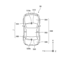
- FIG. 1A is a top view of a vehicle 50 equipped with an antenna device 1 according to an embodiment.
- FIG. 1B is a view of a windshield 510 of a vehicle 50 equipped with an antenna device 1 according to an embodiment and its surroundings, viewed from the left of the vehicle 50.
- FIG. 1C is a view of a rear windshield 520 of a vehicle 50 equipped with an antenna device 1 according to an embodiment and its surroundings, viewed from the left of the vehicle 50.
- FIG. 1A shows the mounting position of the antenna device 1 according to an embodiment on the vehicle 50.
- the matters described below with reference to FIGS. 1A to 1C relate not only to the antenna device 1 according to an embodiment, but also to a mounting method of the antenna device 1 according to an embodiment.
- the antenna device 1 includes a front antenna 10A and a rear antenna 10B.
- the front antenna 10A can ensure directivity in the front and both left and right directions of the vehicle 50
- the rear antenna 10B can ensure directivity in the rear and both left and right directions of the vehicle 50.
- the front antenna 10A and the rear antenna 10B are located on opposite sides of each other in the X direction.
- the antenna device 1 can have omnidirectional directivity by the front antenna 10A and the rear antenna 10B. That is, compared to the case where only one of the front antenna 10A and the rear antenna 10B is used, directivity can be ensured over a wide range.
- the antenna device 1 does not have to include both the front antenna 10A and the rear antenna 10B, and may include only one of the front antenna 10A and the rear antenna 10B.
- the antenna device 1 may further include an additional antenna corresponding to the front antenna 10A or the rear antenna 10B in addition to at least one of the front antenna 10A and the rear antenna 10B.
- the additional antenna may be disposed on glass other than the windshield 510 and the rear glass 520, such as a side glass or a rear quarter glass, or on a part of the vehicle 50, such as a spoiler, a bumper, a pillar, or a roof 502.
- the glass on which the additional antenna is disposed is a dielectric material, such as a radio wave-transmitting material or a light-transmitting material.
- the additional antenna is disposed with a view to the design of the vehicle 50 and not to obstruct the visibility from inside the vehicle 50.
- the front antenna 10A and rear antenna 10B are V2X (Vehicle-to-Everything) antennas.
- the front antenna 10A and rear antenna 10B may be other antennas such as DSRC (Dedicated Short Range Communications), ETC (Electronic Toll Collection), WiFi (registered trademark), Bluetooth (registered trademark), GNSS (Global Navigation Satellite System), 5G (5th generation mobile communication system), LTE (Long Term Evolution), etc.
- DSRC Dedicated Short Range Communications
- ETC Electronic Toll Collection
- WiFi registered trademark
- Bluetooth registered trademark
- GNSS Global Navigation Satellite System
- 5G Fifth Generation mobile communication system
- LTE Long Term Evolution
- the front antenna 10A and the rear antenna 10B are the same antenna. Therefore, the directional characteristics, half-value angle, compatible frequencies, and compatible media of the front antenna 10A are the same as the directional characteristics, half-value angle, compatible frequencies, and compatible media of the rear antenna 10B. However, the directional characteristics, half-value angle, compatible frequencies, and compatible media of the front antenna 10A and the directional characteristics, half-value angle, compatible frequencies, and compatible media of the rear antenna 10B may be different from each other.
- the front antenna 10A and the rear antenna 10B are illustrated as a generally rectangular parallelepiped antenna case that houses an antenna element such as a patch antenna. Unless otherwise specified below, in each figure, the front antenna 10A and the rear antenna 10B are illustrated as a generally rectangular parallelepiped antenna case.
- the generally rectangular parallelepiped antenna case of the front antenna 10A and the rear antenna 10B has a similar configuration to, for example, the front antenna case 110A described later with reference to Figure 2.
- the vehicle 50 according to the embodiment is a sedan-type automobile.
- the vehicle 50 may be any type of automobile.
- the vehicle 50 may be an automobile other than a sedan-type, such as a van type or an SUV (Sport Utility Vehicle) type.
- the vehicle 50 according to the embodiment will be described as a sedan-type automobile.
- the vehicle 50 includes a body 500, a windshield 510, and a rear windshield 520.
- the body 500 includes a roof 502, a bonnet 504, and a trunk lid 506.
- the roof 502 is not particularly limited, but may be, for example, a steel roof, a glass roof, a resin roof, a carbon roof, or a combination thereof.
- the bonnet 504 and the trunk lid 506 are conductive metal sheets made of materials such as aluminum and steel. However, a portion of the bonnet 504 and the trunk lid 506 may be made of a resin part.
- a hatchback may be used instead of the trunk lid 506.
- the roof 502 When viewed from the Z direction, the roof 502 is located approximately in the center of the body 500 in the X direction.
- the bonnet 504 When viewed from the Z direction, the bonnet 504 is located in the front portion of the body 500 in the X direction.
- the windshield 510 When viewed from the Z direction, the windshield 510 is located between the front end of the roof 502 and the rear end of the bonnet 504 in the X direction.
- the windshield 510 is a dielectric.
- the windshield 510 is a radio wave transmitting body that transmits radio waves between the interior of the vehicle 50 and the space in front of the vehicle 50.
- the windshield 510 is also a light transmitting body that transmits light such as visible light between the interior of the vehicle 50 and the space in front of the vehicle 50.
- the trunk lid 506 When viewed from the Z direction, the trunk lid 506 is located at the rear part of the body 500 in the X direction.
- the rear glass 520 When viewed from the Z direction, the rear glass 520 is located between the rear end of the roof 502 and the front end of the trunk lid 506 in the X direction.
- the rear glass 520 is a dielectric.
- the rear glass 520 is a radio wave transmitting body that transmits radio waves between the interior of the vehicle 50 and the space in the rear of the vehicle 50.
- the rear glass 520 is also a light transmitting body that transmits light such as visible light between the interior of the vehicle 50 and the space in the rear of the vehicle 50.
- the front antenna 10A is arranged with the radiation surface from which the radio waves of the front antenna 10A are emitted facing the front of the vehicle 50.
- the radiation surface of the front antenna 10A is the front surface of the front antenna 10A.
- the type of antenna of the front antenna 10A is not particularly limited.
- the front antenna 10A may be a patch antenna or a dipole type antenna, or may be an antenna of another type.
- the windshield 510 is arranged in front of the radiation surface of the front antenna 10A. That is, the front antenna 10A is arranged on the rear side of the windshield 510. Therefore, the front antenna 10A is arranged on the passenger compartment side of the windshield 510.
- the front antenna 10A radiates radio waves toward the windshield 510.
- the bonnet 504 is located below and in front of the front antenna 10A.
- the front antenna 10A is fixed to the rear surface of the windshield 510.
- the rear surface of the windshield 510 is the surface of the windshield 510 facing the passenger compartment.
- the front antenna 10A may be disposed above or inside the dashboard located between the bottom edge of the windshield 510 and the rear end of the hood 504.
- the front antenna 10A may be disposed in a state where it is covered by a resin cover together with other electrical equipment.
- the portion of the windshield 510 that overlaps with the image of the front antenna 10A projected in the X direction will be referred to as the front overlap portion 510a.
- the image of the front antenna 10A is formed by projecting the approximately rectangular parallelepiped antenna case of the front antenna 10A toward the windshield 510 parallel to the X direction.
- two dashed lines indicating the front overlap portion 510a extend forward from the upper and lower surfaces of the front antenna 10A.
- the front overlap portion 510a is the portion of the windshield 510 located between the two dashed lines. The same applies to the front overlap portions 510a shown in FIGS. 6A, 6B, 8, 11, and 13 described below.
- the front overlapping portion 510a when viewed from the Z direction, the front overlapping portion 510a is located in approximately the center in the left-right direction of the windshield 510. However, if other electrical equipment such as wipers, sensors, and dashcams, or black ceramics are located near the front antenna 10A, the front overlapping portion 510a may be located in a position shifted in the Y direction from approximately the center in the left-right direction of the windshield 510.
- the windshield 510 when viewed from the Y direction, the windshield 510 is inclined at a predetermined angle with respect to the X direction between the lower end portion and the upper end portion of the windshield 510. Specifically, when viewed from the Y direction, the windshield 510 is inclined obliquely upward from the rear end of the bonnet 504 toward the front end of the roof 502. Therefore, when viewed from the Y direction, the lower end portion of the windshield 510 is shifted forward from the upper end portion of the windshield 510 in the X direction, and the upper end portion of the windshield 510 is shifted rearward from the lower end portion of the windshield 510 in the X direction.
- the front overlap portion 510a When viewed from the Y direction, the front overlap portion 510a is shifted toward the side where the lower end portion of the windshield 510 is located, with respect to the central portion between the upper end portion and the lower end portion of the windshield 510. Specifically, the front overlap portion 510a is located at the lower end portion of the windshield 510. However, if other electrical equipment such as wipers, sensors, or dashcams, or black ceramics are located near the front antenna 10A, the front overlapping portion 510a may be located at a suitable offset from the bottom edge of the windshield 510.
- the rear antenna 10B is arranged with the radiation surface from which the radio waves of the rear antenna 10B are emitted facing the rear of the vehicle 50.
- the radiation surface of the rear antenna 10B is the rear surface of the rear antenna 10B.
- the type of antenna of the rear antenna 10B is not particularly limited.
- the rear antenna 10B may be a patch antenna or a dipole type antenna, or may be an antenna of another type.
- the rear window 520 is arranged behind the radiation surface of the rear antenna 10B. In other words, the rear antenna 10B is arranged on the front side of the rear window 520. Therefore, the rear antenna 10B is arranged on the passenger compartment side of the rear window 520.
- the rear antenna 10B radiates radio waves toward the rear window 520.
- the trunk lid 506 is located below and behind the rear antenna 10B.
- the rear antenna 10B is fixed to the front surface of the rear window 520.
- the front surface of the rear window 520 is the surface of the rear window 520 facing the interior of the vehicle.
- the rear antenna 10B may be disposed above or inside a rear parcel shelf located between the lower end of the rear window 520 and the front end of the trunk lid 506.
- the rear antenna 10B may be disposed in a state where it is covered with a plastic cover together with other electrical equipment.
- the portion of the rear glass 520 that overlaps with the image of the rear antenna 10B projected in the X direction will be referred to as the rear overlap portion 520a.
- the image of the rear antenna 10B is formed by projecting the approximately rectangular parallelepiped antenna case of the rear antenna 10B parallel to the X direction onto the rear glass 520.
- two dashed lines indicating the rear overlap portion 520a extend rearward from the upper and lower surfaces of the rear antenna 10B.
- the rear overlap portion 520a is the portion of the rear glass 520 located between the two dashed lines. The same applies to the rear overlap portion 520a shown in FIG. 10A and FIG. 10B described later.
- the rear overlapping portion 520a when viewed from the Z direction, the rear overlapping portion 520a is located approximately in the center of the rear glass 520 in the left-right direction. However, if other electrical equipment such as wipers, sensors, or dashcams, or black ceramics are located near the rear antenna 10B, the rear overlapping portion 520a may be shifted in the Y direction from approximately the center of the rear glass 520 in the left-right direction.
- the rear glass 520 when viewed from the Y direction, the rear glass 520 is inclined at a predetermined angle with respect to the X direction between the lower end portion and the upper end portion of the rear glass 520. Specifically, when viewed from the Y direction, the rear glass 520 is inclined obliquely upward from the front end of the trunk lid 506 toward the rear end of the roof 502. Therefore, when viewed from the Y direction, the lower end portion of the rear glass 520 is shifted rearward from the upper end portion of the rear glass 520 in the X direction, and the upper end portion of the rear glass 520 is shifted forward from the lower end portion of the rear glass 520 in the X direction.
- the rear overlap portion 520a When viewed from the Y direction, the rear overlap portion 520a is shifted toward the side where the lower end portion of the rear glass 520 is located, with respect to the central portion between the upper end portion and the lower end portion of the rear glass 520. Specifically, the rear overlap portion 520a is located at the lower end portion of the rear glass 520. However, if other electrical equipment such as wipers, sensors, or dashcams, or black ceramics are located near the rear antenna 10B, the rear overlapping portion 520a may be located at a position appropriately offset from the bottom end of the rear glass 520.
- FIG. 2 is a perspective view showing an example of the configuration of the front antenna 10A according to the embodiment.
- the matters described for the front antenna 10A using FIG. 2 can also be similarly applied to the rear antenna 10B.
- the configurations of the front antenna 10A and the rear antenna 10B are not limited to the example configuration shown in FIG. 2.
- the front antenna 10A includes a front antenna case 110A and a front cable 120A.
- the front antenna case 110A has a generally rectangular parallelepiped shape.
- the front antenna case 110A covers an antenna element not shown in FIG. 2. This antenna element is, for example, a patch antenna. However, the antenna covered by the front antenna case 110A is not limited to a patch antenna.
- the front antenna case 110A is radio wave transparent.
- the front antenna case 110A is made of, for example, resin.
- the front antenna case 110A is provided with an attachment structure.
- the front antenna case 110A is fixed to a fixing structure such as a bracket provided on the vehicle 50 via the attachment structure.
- the front cable 120A is pulled out from the front antenna case 110A.
- the front cable 120A is electrically connected to the antenna element covered by the front antenna case 110A.
- the signal obtained from the antenna element covered by the front antenna case 110A is output via the front cable 120A.
- the method of outputting the signal obtained from the antenna element is not limited to the method using the front cable 120A.
- a board such as a printed circuit board (PCB) on which the antenna element is mounted and a connector such as a coaxial connector may be electrically connected to each other. When the board and the connector are electrically connected to each other, the signal obtained from the antenna element is output via the board and the connector.
- PCB printed circuit board
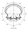
- FIG. 3A is a diagram of the directional gain in the horizontal plane of the antenna device 1 according to the first embodiment when mounted on a vehicle 50.
- FIG. 3B is a diagram of the directional gain in the horizontal plane of the antenna device 1K according to the comparative example when mounted on a vehicle 50.
- FIG. 4 is a top view of the vehicle 50 on which the antenna device 1K according to the comparative example is mounted.
- the horizontal plane is a plane perpendicular to the Z direction.
- the antenna device 1 according to the first embodiment is an example of the antenna device 1 according to the embodiment.
- the front overlapping portion 510a is located at the bottom end portion of the windshield 510.
- the rear overlapping portion 520a is located at the bottom end portion of the rear windshield 520.
- the front antenna 10A and the rear antenna 10B are the same antenna. In other words, the half-value angle of the characteristics of the front antenna 10A alone and the half-value angle of the characteristics of the rear antenna 10B alone are the same.
- An antenna device 1K according to a comparative example will be described with reference to FIG. 4.
- the antenna device 1K according to the comparative example is similar to the antenna device 1 according to the first embodiment, except for the following points.
- the front antenna 10A according to the first embodiment and the front antenna 10A according to the comparative example are the same antenna.
- the front overlapping portion 510aK according to the comparative example is located in the center part in the left-right direction of the windshield 510, similar to the front overlapping portion 510a according to the first embodiment.
- the front overlapping portion 510aK according to the comparative example is located in the center part between the upper end part and the lower end part of the windshield 510, unlike the front overlapping portion 510a according to the first embodiment.
- the rear antenna 10B according to the first embodiment and the rear antenna 10B according to the comparative example are the same antenna.
- the rear overlapping portion 520aK according to the comparative example is located in the center part in the left-right direction of the rear glass 520, similar to the rear overlapping portion 520a according to the first embodiment.
- the rear overlapping portion 520aK according to the comparative example is located in the center part between the upper end part and the lower end part of the rear glass 520, unlike the rear overlapping portion 520a according to the first embodiment.
- the numbers on the periphery of the gain diagrams in Fig. 3A and Fig. 3B indicate the direction (unit: °).
- the numbers on the gain diagrams in Fig. 3A and Fig. 3B from the center to the 270° direction indicate the gain (unit: dBi).
- the 0° direction is the front side of the vehicle 50
- the 180° direction is the rear side of the vehicle 50
- the 90° direction is the left side of the vehicle 50
- the 270° direction is the right side of the vehicle 50.
- the solid line pattern in Fig. 3A shows the horizontal plane directional gain of the front antenna 10A according to the first embodiment.
- FIG. 3A shows the horizontal plane directional gain of the rear antenna 10B according to the first embodiment.
- the solid line pattern in Fig. 3B shows the horizontal plane directional gain of the front antenna 10A according to the comparative example.
- the dashed line pattern in Fig. 3B shows the horizontal plane directional gain of the rear antenna 10B according to the comparative example.
- the gain in the 90° direction of the front antenna 10A according to the first embodiment is -1.58 dBi.
- the gain in the 90° direction of the front antenna 10A according to the comparative example is -12.15 dBi. It can therefore be seen that the gain in the 90° direction of the front antenna 10A according to the first embodiment is significantly greater than the gain in the 90° direction of the front antenna 10A according to the comparative example. Therefore, even if the front antenna 10A according to the first embodiment and the front antenna 10A according to the comparative example are the same antenna, it is possible to increase the half-width of the front antenna 10A by changing the mounting position of the front antenna 10A, thereby improving the gain of the front antenna 10A in the left-right direction of the vehicle 50.
- the gain in the 90° direction of the rear antenna 10B according to the first embodiment is -1.53 dBi.
- the gain in the 90° direction of the rear antenna 10B according to the comparative example is -11.24 dBi. It can therefore be seen that the gain in the 90° direction of the rear antenna 10B according to the first embodiment is significantly increased compared to the gain in the 90° direction of the rear antenna 10B according to the comparative example. Therefore, even if the rear antenna 10B according to the first embodiment and the rear antenna 10B according to the comparative example are the same antenna, it is possible to increase the half-width of the rear antenna 10B by changing the mounting position of the rear antenna 10B, thereby improving the gain of the rear antenna 10B in the left-right direction of the vehicle 50.
- the difference between the maximum and minimum values of the gain of the front antenna 10A at angles of 0° to 90° and 270° to less than 360° and the gain of the rear antenna 10B at angles of 90° to 270° is 8.21 dB.
- the difference between the maximum and minimum values of the gain of the front antenna 10A at angles of 0° to 90° and 270° to less than 360° and the gain of the rear antenna 10B at angles of 90° to 270° is 16.02 dB.
- the ripple is reduced more than in the comparative example. Therefore, it can be seen that the antenna device 1 according to the first embodiment has directivity over a wider range than the antenna device 1K according to the comparative example. In particular, it can be said that the antenna device 1 according to the first embodiment has omnidirectional directivity.
- the half-value angle of the single characteristic of the front antenna 10A and the half-value angle of the single characteristic of the rear antenna 10B are the same. However, the half-value angle of the single characteristic of the front antenna 10A and the half-value angle of the single characteristic of the rear antenna 10B may be different from each other. When the half-value angle of the single characteristic of the front antenna 10A and the half-value angle of the single characteristic of the rear antenna 10B are different from each other, for example, the half-value angles of the front antenna 10A and the rear antenna 10B can be determined so that the combined horizontal plane directional gain of the front antenna 10A and the rear antenna 10B has omnidirectional directivity.
- the radiation characteristics of the front antenna 10A when the windshield 510 is located in front of the radiation surface of the front antenna 10A will be described.
- the closer the incident angle of the radio waves radiated from the front antenna 10A to the rear surface of the windshield 510 is to a right angle the more the radio waves radiated from the front antenna 10A are scattered at the rear surface of the windshield 510, and the more difficult they are to penetrate the windshield 510, and the lower the gain.
- the front antenna 10A overlaps with the center part between the upper end part and the lower end part of the windshield 510 in the front-rear direction of the vehicle 50.
- the front antenna 10A overlaps with the lower end part of the windshield 510 in the front-rear direction of the vehicle 50. Therefore, in the embodiment and the first example, the irradiation area of the radio waves radiated forward and downward from the front antenna 10A on the rear surface of the windshield 510 can be made smaller than the irradiation area of the radio waves radiated forward and downward from the front antenna 10A on the rear surface of the windshield 510 in the comparative example.
- the gain of the embodiment and the first example can be made higher than the gain of the comparative example by the amount that scattering of the radio waves on the rear surface of the windshield 510 is suppressed.
- FIG. 5A is a diagram of the horizontal directional gain when the front antenna 10A overlaps with the upper end, center, or lower end of the windshield 510 in the front-rear direction of the vehicle 50.
- the center of the windshield 510 is the center between the upper end and lower end of the windshield 510 when viewed from the Y direction, with reference to FIG. 1B.
- the 0° direction is the front side of the vehicle 50
- the 180° direction is the rear side of the vehicle 50
- the 90° direction is the left side of the vehicle 50
- the 270° direction is the right side of the vehicle 50.
- the windshield 510 is disposed on the 0° side of the front antenna 10A.
- the dotted line pattern, dashed line pattern, and solid line pattern in FIG. 5A respectively show the horizontal directional gain when the front antenna 10A overlaps with the upper end, center, and lower end of the windshield 510 in the X direction.
- the gain in the 90° direction when the front antenna 10A overlaps with the upper end portion, the center portion, and the lower end portion of the windshield 510 in the X direction is -11.99 dBi, -12.15 dBi, and -1.58 dBi, respectively.
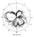
- FIG. 5B is a diagram of vertical directional gain when the front antenna 10A overlaps with the upper end, center, or lower end of the windshield 510 in the front-rear direction of the vehicle 50.
- the center of the windshield 510 is the center between the upper end and lower end of the windshield 510 when viewed from the Y direction, with reference to FIG. 1B.
- the 90° direction is the front side of the vehicle 50
- the -90° direction is the rear side of the vehicle 50
- the 0° direction is the upper side of the vehicle 50
- the 180° direction is the lower side of the vehicle 50.
- the windshield 510 is disposed on the 90° side of the front antenna 10A.
- the dotted line pattern, dashed line pattern, and solid line pattern in FIG. 5B respectively indicate the horizontal directional gain when the front antenna 10A overlaps with the upper end, center, and lower end of the windshield 510 in the X direction.
- the gain deviation (the difference between the maximum and minimum gain values) in the 60° to 120° range becomes smaller as the front overlap portion 510a moves from the top to the bottom of the windshield 510.
- the gain of the front antenna 10A is higher when the front antenna 10A overlaps the bottom end portion of the windshield 510 in the X direction than when the front antenna 10A overlaps the top end portion of the windshield 510 in the X direction.
- the irradiation area of the radio waves radiated forward and downward from the front antenna 10A on the rear surface of the windshield 510 is smaller when the front antenna 10A overlaps the bottom end portion of the windshield 510 in the X direction than when the front antenna 10A overlaps the top end portion of the windshield 510 in the X direction, and scattering of the radio waves on the rear surface of the windshield 510 can be suppressed.
- the front antenna 10A overlaps with the lower end portion of the windshield 510 in the X direction. Therefore, in the first embodiment, directivity can be stably ensured over a wide range compared to when the front antenna 10A overlaps with the upper end portion or center portion of the windshield 510 in the X direction. Ensuring directivity over a wide range in the first embodiment can be achieved without adding antennas to both the left and right sides of the vehicle 50. Therefore, in the first embodiment, directivity can be ensured over a wide range with a small number of antennas. The larger the half-value angle of the front antenna 10A, the better the stable ensuring of directivity over a wide range in the first embodiment.
- the front overlap portion 510a When viewed from the Y direction, the front overlap portion 510a may not be located at the bottom end of the windshield 510, but may be located at a portion that is a predetermined distance forward of the center portion of the windshield 510 in the Z direction. When viewed from the Y direction, the front overlap portion 510a is located forward of the center portion of the windshield 510 in the Z direction, it is possible to ensure directivity over a wide range with a smaller number of antennas, compared to when the front overlap portion 510a is located at the center portion of the windshield 510 in the Z direction or at the upper end portion of the windshield 510 when viewed from the Y direction.
- the embodiment and the first example utilize the characteristics of radio waves radiated from the front antenna 10A or the rear antenna 10B propagating through conductive sheet metal such as the bonnet 504 and the trunk lid 506.
- the first embodiment and the first example utilize the characteristics of radio waves radiated from each antenna propagating through a conductor to ensure the gain of the antenna device 1 in the left-right direction of the vehicle 50.
- a hatchback may be used as a conductor in place of the trunk lid 506 to propagate radio waves.
- a hatchback can also be used to propagate radio waves in the same manner as the trunk lid 506.
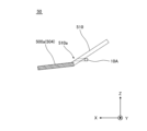
- FIG. 6A is a diagram showing the configuration of a portion of a vehicle 50 in which a front conductor 500a is provided below and in front of the front antenna 10A.
- FIG. 6B is a diagram showing the configuration of a portion of a vehicle 50 in which a front conductor 500a is not provided below and in front of the front antenna 10A.
- FIGS. 6A and 6B show comparative configurations with and without a front conductor 500a below and in front of the front antenna 10A.
- the bonnet 504 serves as the front conductor 500a.
- the front conductor 500a is disposed forward of the lower end portion of the windshield 510 when viewed from the Y direction. Specifically, the front conductor 500a extends downward and forward from the lower end portion of the windshield 510 when viewed from the Y direction.
- FIG. 7A is a diagram of horizontal directional gain when a front conductor 500a is provided below and in front of the front antenna 10A and when it is not.
- the relationship between the numbers on the outer periphery of the gain diagram in FIG. 7A and the directions indicated by these numbers is the same as the relationship between the numbers on the outer periphery of the gain diagram in FIG. 5A and the directions indicated by these numbers.
- the dashed line pattern indicates the horizontal directional gain when a front conductor 500a is provided below and in front of the front antenna 10A as shown in FIG. 6A.
- the solid line pattern indicates the horizontal directional gain when no front conductor 500a is provided below and in front of the front antenna 10A as shown in FIG. 6B.
- FIG. 7B is a diagram of vertical-plane directional gain when a front conductor 500a is provided below and in front of the front antenna 10A and when it is not provided.
- the relationship between the numbers on the periphery of the gain diagram in FIG. 7B and the directions indicated by these numbers is the same as the relationship between the numbers on the periphery of the gain diagram in FIG. 5B and the directions indicated by these numbers.
- the dashed line pattern indicates the vertical-plane directional gain when a front conductor 500a is provided below and in front of the front antenna 10A as shown in FIG. 6A.
- the solid line pattern indicates the vertical-plane directional gain when a front conductor 500a is not provided below and in front of the front antenna 10A as shown in FIG. 6B.
- the directional gain in the horizontal plane is almost the same regardless of whether the front conductor 500a is present or not.
- the gain deviation (the difference between the maximum and minimum gain values) in the range of 60° to 120° forward of the radiation direction of the front antenna 10A is suppressed more when the front conductor 500a is provided than when the front conductor 500a is not provided.
- the radio waves radiated from the front antenna 10A can propagate on the upper surface of the front conductor 500a arranged in front of the windshield 510 (outside as viewed from inside the vehicle cabin). Therefore, it is possible to ensure the gain of the front antenna 10A in the left-right direction of the vehicle 50 compared to when the front conductor 500a is not provided.
- the gain of the front antenna 10A in the left-right direction of the vehicle 50 can be improved as the half-value angle of the front antenna 10A increases.
- the inventors' verification results show that the angle of the bonnet 504 and trunk lid 506 relative to the X direction affects the radiation characteristics of the front antenna 10A and rear antenna 10B.
- FIG. 8 shows model examples of different angles of the front conductor 500a relative to the horizontal direction.
- the front end of the front conductor 500a can move downward around the portion of the front conductor 500a near the lower end of the windshield 510.
- FIG. 9A is a diagram of directional gain in the horizontal plane at different angles of the front conductor 500a relative to the horizontal direction.
- FIG. 9B is a diagram of directional gain in the vertical plane at different angles of the front conductor 500a relative to the horizontal direction.
- the relationship between the numbers on the periphery of the gain diagram in FIG. 9A and the directions indicated by these numbers is the same as the relationship between the numbers on the periphery of the gain diagram in FIG. 5A and the directions indicated by these numbers.
- the relationship between the numbers on the periphery of the gain diagram in FIG. 9B and the directions indicated by these numbers is the same as the relationship between the numbers on the periphery of the gain diagram in FIG. 5B and the directions indicated by these numbers.
- the front end of the front conductor 500a is tilted downward by 30°, 60°, or 90° around a portion of the front conductor 500a close to the lower end of the windshield 510, as compared to the state in which the inclination of the front conductor 500a with respect to the X direction is 0° as shown in FIG. 8.
- the inclination of the front conductor 500a with respect to the X direction is 0°, meaning that the front conductor 500a is parallel to the X direction.
- the solid line patterns, dashed line patterns, dotted line patterns, and dashed-dotted line patterns in FIG. 9A and 9B show the gain when the inclination of the front conductor 500a with respect to the X direction is 0°, 30°, 60°, and 90°, respectively.
- the directional gain in the horizontal plane between 0° and 90° and between 270° and 360° is lowest when the inclination of the front conductor 500a with respect to the X direction is 90°, and it is found that the gain improves as the front conductor 500a gradually approaches the X direction.
- the front conductor 500a is perpendicular to the X direction, it can be said that the front conductor 500a hardly contributes to the radiation of radio waves from the front antenna 10A.
- the radio waves radiated from the front antenna 10A can propagate through the front conductor 500a, and the gain on the front side of the front antenna 10A improves.
- the radio waves propagate to an elevation angle of -6°, and the gain in the depression angle direction from the horizontal plane improves. Therefore, when communicating with others through V2X communication using the front antenna 10A, it is desirable to set the inclination of the front conductor 500a with respect to the X direction to, for example, between -30° and +30°. Setting the inclination of the front conductor 500a with respect to the X direction within this range can improve the gain of the front antenna 10A.
- the variation in the vertical-plane directional gain in the elevation angle range on the front side of the front antenna 10A i.e., the variation in the vertical-plane directional gain from 60° to 120°, is smaller when the inclination of the front conductor 500a with respect to the X direction is 0° than when the inclination of the front conductor 500a with respect to the X direction is greater than 0°. Therefore, when the front conductor 500a approaches the X direction, the front antenna 10A can stably radiate radio waves toward the elevation angle range on the front side.
- the shape of the front conductor 500a is not particularly limited.
- the shape of the front conductor 500a may be flat.
- a portion of the front conductor 500a may have an uneven or rounded shape.
- by making the front conductor 500a slanted downward as it approaches the front end of the body 500 it is possible to improve the propagation characteristics of radio waves from the horizontal plane downward and increase the directional gain of the depression angle.
- FIG. 10A is a diagram showing a first example of a rear conductor 500b according to an embodiment.
- FIG. 10B is a diagram showing a second example of a rear conductor 500b according to an embodiment.
- the rear conductor 500b shown in FIG. 10A or FIG. 10B is a hatchback or a structure similar to a hatchback.
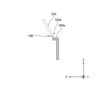
- the hatchback of a van is nearly perpendicular to the X direction. Therefore, as shown in FIG. 10A or FIG. 10B, a portion of the rear conductor 500b may extend from the lower end portion of the rear window 520 approximately parallel to the X direction.
- the horizontal plane directional gain of the rear antenna 10B can be improved compared to when the rear conductor 500b is simply perpendicular to the X direction. In the example shown in FIG.
- the rear conductor 500b includes a portion approximately parallel to the X direction and a portion extending from the front end of the portion approximately parallel to the X direction and approximately parallel to the Z direction.
- the rear conductor 500b includes a portion that is approximately parallel to the X direction and a portion that extends from the rear end of the portion that is approximately parallel to the X direction and is approximately parallel to the Z direction.
- the rear conductor 500b can be formed by various methods. For example, a portion of the body 500 may be bent into an L-shape. Alternatively, a conductor approximately parallel to the Z direction may be provided in advance, and a conductor approximately parallel to the X direction may be added later. Alternatively, a spoiler may be used. The rear conductor 500b may be used as a single conductor. Alternatively, the rear conductor 500b may be integrated with the body 500. The rear conductor 500b may be attached to the body 500 in a state where it is provided on at least one of the outside and inside of the resin material.
- the influence of the black ceramic 512 provided on the windshield 510 and the distance between the black ceramic 512 and the front antenna 10A will be described.
- the matters described below regarding the influence of the black ceramic 512 provided on the windshield 510 and the distance between the black ceramic 512 and the front antenna 10A can also be similarly applied to the influence of the black ceramic provided on the rear windshield 520 and the distance between the black ceramic and the rear antenna 10B.
- Black ceramic is printed on the peripheral surface of the glass such as the front glass 510 and the rear glass 520.
- the black ceramic has the role of protecting the adhesive used when assembling the glass such as the front glass 510 and the rear glass 520 to the body 500.
- Black ceramic generally contains alumina and titanium carbide added to the alumina, and contains other substances as necessary.
- Alumina is a substance with a small dielectric tangent.
- titanium carbide is a substance with electrical conductivity. Therefore, some of the electromagnetic waves that pass through the black ceramic may flow as an electric current to the titanium carbide and be converted into heat. This phenomenon is the same as the behavior of a dielectric loss type radio wave absorber, and is a factor that inhibits the transmission of radio waves.
- antennas such as the front antenna 10A and the rear antenna 10B are placed on the edge of the glass such as the front glass 510 and the rear glass 520
- the front overlapping portion 510a and the black ceramic are offset from each other.
- the rear overlap portion 520a and the black ceramic are offset from each other.
- FIG. 11 shows the arrangement of the black ceramic 512 of the windshield 510 and the front antenna 10A as viewed from the left side of the vehicle 50.
- the front antenna 10A is shown as an antenna case with a substantially rectangular parallelepiped shape that houses an antenna element.
- the black ceramic 512 is provided on the rear surface of the lower end of the windshield 510. Light is barely transmitted through the black ceramic 512. Therefore, the portion of the lower end of the windshield 510 where the black ceramic 512 is provided does not function as a light-transmitting body. Therefore, the lower end of the portion of the windshield 510 that functions as a light-transmitting body is the upper end of the black ceramic 512.
- the front overlap portion 510a and the black ceramic 512 are positioned offset from each other.
- the distance L from the height of the top end of the black ceramic 512 to the bottom surface of the front antenna 10A is, for example, 20 mm.
- the distance L shown in FIG. 11 can be freely set as long as the black ceramic 512 does not interfere with the radio waves radiated from the rear antenna 10B. If the black ceramic 512 is in the radiation direction of the radio waves from the front antenna 10A, the gain of the front antenna 10A may decrease. For this reason, the front antenna 10A is positioned at a predetermined distance from the black ceramic 512 in the Z direction.
- the rear antenna 10B can be positioned at a predetermined distance from the black ceramic provided at the bottom edge of the rear glass 520.
- the distance from the height of the top edge of the black ceramic provided at the bottom edge of the rear glass 520 to the bottom surface of the housing of the rear antenna 10B is, for example, 5 mm. This distance can be freely set as long as the black ceramic does not interfere with the radio waves radiated from the rear antenna 10B.
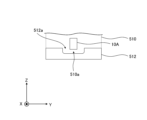
- FIG. 12 is a view of the front antenna 10A, windshield 510, and black ceramic 512 as viewed from the front of the vehicle 50.
- the front antenna 10A is illustrated as an antenna case having a substantially rectangular parallelepiped shape that houses an antenna element.
- the black ceramic 512 defines a recess 512a.
- the recess 512a at least partially surrounds the front overlapping portion 510a.
- the recess 512a at least partially surrounds the lower end of the front antenna 10A. Therefore, the recess 512a can prevent the front antenna 10A and the black ceramic 512 from overlapping in the X direction. Therefore, compared to when the recess 512a is not provided, the degree of freedom in the mounting position of the front antenna 10A can be increased. Therefore, compared to when the recess 512a is not provided, when viewed from the front, the front antenna 10A can be positioned closer to the lower end of the windshield 510, and the gain of the front antenna 10A can be improved.
- the black ceramic provided on the rear glass 520 may also define a recess corresponding to the recess 512a of the black ceramic 512 provided on the front glass 510.
- the angle of the windshield 510 with respect to the X direction contributes to at least one of the transmission and scattering of radio waves irradiated from the front antenna 10A.
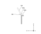
- the angle of the rear surface of the front overlapping portion 510a with respect to the X direction is set to 10° or more and 40° or less, the reflection of radio waves by the windshield 510 can be minimized.
- the angle of the rear windshield 520 with respect to the X direction is approximately 31°.
- the angle of the rear windshield 520 with respect to the X direction is approximately 23.5°.
- the angles of the windshield 510 and the rear windshield 520 with respect to the X direction may be freely set.
- the distance between the front antenna 10A and the windshield 510 also contributes to the radiation of radio waves from the front antenna 10A. Therefore, it is desirable to position the front antenna 10A and the windshield 510 with a certain distance between them. The same applies to the rear antenna 10B and the rear windshield 520.
- FIG. 13 shows the arrangement of the front antenna 10A and the windshield 510 as viewed from the left side of the vehicle 50.
- the front antenna 10A is shown as an antenna case having a substantially rectangular parallelepiped shape that houses an antenna element.
- the X-direction distance Gx between the front surface of the front antenna 10A and the portion on the rear surface of the windshield 510 closest to the front surface of the front antenna 10A in the X-direction is 20 mm
- the Z-direction distance Gz between the top surface of the front antenna 10A and the portion on the rear surface of the windshield 510 closest to the top surface of the front antenna 10A in the Z-direction is 11.8 mm.
- the X-direction distance between the rear surface of the rear antenna 10B and the portion on the front surface of the rear windshield 520 closest to the rear surface of the rear antenna 10B in the X-direction is 20 mm
- the Z-direction distance between the top surface of the rear antenna 10B and the portion on the front surface of the rear windshield 520 closest to the top surface of the rear antenna 10B in the Z-direction is 8.5 mm.
- the radiation characteristics, impedance, and other characteristics of the front antenna 10A may change as the front antenna 10A and the windshield 510 approach each other. Therefore, it is desirable that the distance Gx shown in FIG. 13 is, for example, 1/4 times or more of the wavelength of the operating frequency of the front antenna 10A. On the other hand, if the front antenna 10A and the windshield 510 are too far away from each other, the radio waves emitted from the front antenna 10A may be reflected by the windshield 510. Therefore, it is desirable that the distance Gx shown in FIG. 13 is, for example, 1/2 times or less of the wavelength of the operating frequency of the front antenna 10A. It is desirable that the distance Gz shown in FIG. 13 is, for example, 1/10 times or more of the wavelength of the operating frequency of the front antenna 10A. The same applies to the distance between the rear antenna 10B and the rear windshield 520.
- the distance between the front antenna 10A and the windshield 510 and the distance between the rear antenna 10B and the rear windshield 520 are not limited to the above examples. These distances may be freely set if the desired antenna gain can be obtained in any elevation angle and azimuth angle range.
- Antennas such as the front antenna 10A and the rear antenna 10B may overlap a radio wave-transmitting body that is different from glass such as the front windshield 510 and the rear windshield 520.
- radio wave-transmitting bodies include resin bodies such as resin panels, resin covers, and resin parts.
- the resin body has radio wave transmittance.
- the resin body may or may not have optical transmittance.
- the resin body is disposed, for example, on the interior side of the vehicle cabin.
- the resin body is provided for purposes such as fixing the antenna or peripheral parts of the antenna, improving aesthetics and design, and improving dustproofing, waterproofing, or durability.
- a resin body such as a resin panel may be present on the radiation direction side of the antenna.
- the resin body may be disposed between the antenna and the glass.
- a resin body such as a resin cover may cover at least a portion of the antenna.
- the resin body may cover the antenna with the side of the resin body where the glass is located relative to the antenna open.
- the antenna may be disposed within a space surrounded by the resin body and the glass.
- the resin body may cover the antenna including the side where the glass is located relative to the antenna.
- the antenna may be disposed within a space surrounded by the resin body.
- a resin body such as a resin part may be provided as a bracket to secure the antenna to the vehicle.
- the resin body is inclined obliquely upward in the front-rear direction from the front to the rear.
- the antenna radiates radio waves from the rear toward the resin body.
- the part of the resin body that overlaps with the image of the antenna projected in the front-rear direction is referred to as the overlapping part of the resin body.
- the overlapping part of the resin body is shifted toward the side where the lower end part of the resin body is located with respect to the center part between the upper end part and the lower end part of the resin body.
- a conductor such as a metal plate may be provided below the front of the antenna.
- the conductor is disposed forward of the lower end part of the resin body.
- the antenna device comprises an antenna having two end portions located opposite each other and radiating radio waves from the other side toward a radio wave transparent body that is inclined at a predetermined angle with respect to a predetermined direction between the two end portions as it moves from one side to the other side in the predetermined direction, and a portion of the radio wave transparent body that overlaps with an image of the antenna projected in the predetermined direction is shifted toward the side where the end portion of one of the two end portions of the radio wave transparent body is located, relative to the central portion between the two end portions of the radio wave transparent body.
- the "predetermined direction” corresponds to the "X direction” in the above-mentioned embodiment and modified examples.
- the "radio wave transparent body” corresponds to the "front windshield” and “rear windshield” in the above-mentioned embodiment and modified examples.
- the "antenna” corresponds to the "front antenna” and “rear antenna” in the above-mentioned embodiment and modified examples.
- scattering of radio waves radiated from the antenna in the radio wave transparent body can be suppressed compared to when the portion of the radio wave transparent body that overlaps with the image of the antenna is located in the center of the radio wave transparent body, or is shifted from the center of the radio wave transparent body to the side where the other end part of the radio wave transparent body is located. Therefore, directivity can be ensured over a wide range with a smaller number of antennas compared to when the portion of the radio wave transparent body that overlaps with the image of the antenna is located in the center of the radio wave transparent body, or is shifted from the center of the radio wave transparent body to the side where the other end part of the radio wave transparent body is located.
- the plurality of antennas are positioned opposite each other in the predetermined direction.
- the above-mentioned aspect ensures directivity over a wide range compared to when a single antenna is used.
- the antenna is positioned with a conductor disposed on one side relative to the end portion on the one side of the radio wave transparent body.
- radio waves radiated from the antenna can propagate through the conductor. Therefore, the antenna gain can be secured compared to the case where no conductor is provided.
- the antenna is positioned in a state in which the portion of the radio wave transparent body that overlaps with the image of the antenna and the black ceramic provided on the radio wave transparent body are misaligned with each other.
- the black ceramic from impeding the transmission of radio waves radiated from the antenna, compared to when the black ceramic overlaps with the portion of the radio wave transparent body that overlaps with the image of the antenna. Therefore, it is possible to improve the gain of the antenna, compared to when the black ceramic overlaps with the portion of the radio wave transparent body that overlaps with the image of the antenna.
- the black ceramic defines a recess that at least partially surrounds the portion of the radio wave transparent body that overlaps with the image of the antenna.
- the recess can prevent the antenna and the black ceramic from overlapping in a specific direction. Therefore, the degree of freedom in the mounting position of the antenna can be increased compared to a case where no recess is provided.
- the antenna and the portion of the radio wave transparent body that overlaps with the image of the antenna are arranged in the specified direction at a distance of more than 1/4 and less than 1/2 the wavelength of the operating frequency of the antenna.
- the above-mentioned aspect it is possible to suppress changes in the antenna characteristics compared to when the distance in a specified direction between the antenna and the portion of the radio wave transparent body where the image of the antenna overlaps is less than 1/4 times the wavelength of the operating frequency of the antenna.
- the radio wave transparent body is a light transparent body.
- the antennas when the antennas are arranged on the light-transmitting body, it is possible to ensure directivity over a wide range with a small number of antennas.
- the antenna is a V2X antenna.
- an antenna in a method for mounting an antenna device, is positioned such that it radiates radio waves from a side toward a radio wave transparent body having both end portions located opposite each other and inclined at a predetermined angle with respect to a predetermined direction between the both end portions as it moves from one side to the other side in the predetermined direction, and a portion of the radio wave transparent body that overlaps with an image of the antenna projected in the predetermined direction is shifted toward the side where the end portion of one of the both end portions of the radio wave transparent body is located, with respect to a central portion between the both end portions of the radio wave transparent body.
- the antennas are positioned opposite each other in the predetermined direction.
- the above-mentioned aspect ensures directivity over a wide range compared to when a single antenna is used.
- the antenna is positioned with a conductor disposed on one side relative to the end portion on the one side of the radio wave transparent body.
- the antenna is positioned such that the portion of the radio wave transparent body that overlaps with the image of the antenna and the black ceramic provided on the radio wave transparent body are offset from each other.
- the antenna gain can be improved compared to when the portion of the radio wave transparent body that overlaps with the antenna image overlaps with the black ceramic.
- the black ceramic defines a recess at least partially surrounding the portion of the radio wave transparent body that overlaps the image of the antenna.
- the antenna and the portion of the radio wave transparent body that overlaps with the image of the antenna are arranged in the specified direction at a distance of more than 1/4 and less than 1/2 the wavelength of the operating frequency of the antenna.
- the radio wave transparent body is a light transparent body.
- the antennas when the antennas are arranged on the light-transmitting body, it is possible to ensure directivity over a wide range with a small number of antennas.
- the antenna is a V2X antenna.
- 1,1K Antenna device 10A Front antenna, 10B Rear antenna, 50 Vehicle, 110A Front antenna case, 120A Front cable, 500 Body, 500a Front conductor, 500b Rear conductor, 502 Roof, 504 Bonnet, 506 Trunk lid, 510 Windshield, 510a, 510aK Front overlapping part, 512 Black ceramic, 512a Recess, 520 Rear glass, 520a, 520aK Rear overlapping part
Landscapes
- Engineering & Computer Science (AREA)
- Remote Sensing (AREA)
- Details Of Aerials (AREA)
Priority Applications (3)
| Application Number | Priority Date | Filing Date | Title |
|---|---|---|---|
| EP23928720.4A EP4685997A1 (en) | 2023-03-22 | 2023-05-29 | Antenna device and installation method for antenna device |
| JP2025508107A JPWO2024195144A1 (https=) | 2023-03-22 | 2023-05-29 | |
| CN202380096137.9A CN120826833A (zh) | 2023-03-22 | 2023-05-29 | 天线装置以及天线装置的搭载方法 |
Applications Claiming Priority (2)
| Application Number | Priority Date | Filing Date | Title |
|---|---|---|---|
| US202363453773P | 2023-03-22 | 2023-03-22 | |
| US63/453,773 | 2023-03-22 |
Publications (1)
| Publication Number | Publication Date |
|---|---|
| WO2024195144A1 true WO2024195144A1 (ja) | 2024-09-26 |
Family
ID=92841676
Family Applications (1)
| Application Number | Title | Priority Date | Filing Date |
|---|---|---|---|
| PCT/JP2023/019932 Ceased WO2024195144A1 (ja) | 2023-03-22 | 2023-05-29 | アンテナ装置及びアンテナ装置の搭載方法 |
Country Status (4)
| Country | Link |
|---|---|
| EP (1) | EP4685997A1 (https=) |
| JP (1) | JPWO2024195144A1 (https=) |
| CN (1) | CN120826833A (https=) |
| WO (1) | WO2024195144A1 (https=) |
Citations (3)
| Publication number | Priority date | Publication date | Assignee | Title |
|---|---|---|---|---|
| JP2012191489A (ja) * | 2011-03-11 | 2012-10-04 | Panasonic Corp | 車両用アンテナ装置 |
| WO2019073667A1 (ja) | 2017-10-13 | 2019-04-18 | 株式会社ヨコオ | パッチアンテナおよび車載用アンテナ装置 |
| WO2021193454A1 (ja) * | 2020-03-24 | 2021-09-30 | Agc株式会社 | 車両用アンテナシステム |
-
2023
- 2023-05-29 CN CN202380096137.9A patent/CN120826833A/zh active Pending
- 2023-05-29 JP JP2025508107A patent/JPWO2024195144A1/ja active Pending
- 2023-05-29 WO PCT/JP2023/019932 patent/WO2024195144A1/ja not_active Ceased
- 2023-05-29 EP EP23928720.4A patent/EP4685997A1/en active Pending
Patent Citations (3)
| Publication number | Priority date | Publication date | Assignee | Title |
|---|---|---|---|---|
| JP2012191489A (ja) * | 2011-03-11 | 2012-10-04 | Panasonic Corp | 車両用アンテナ装置 |
| WO2019073667A1 (ja) | 2017-10-13 | 2019-04-18 | 株式会社ヨコオ | パッチアンテナおよび車載用アンテナ装置 |
| WO2021193454A1 (ja) * | 2020-03-24 | 2021-09-30 | Agc株式会社 | 車両用アンテナシステム |
Non-Patent Citations (1)
| Title |
|---|
| See also references of EP4685997A1 |
Also Published As
| Publication number | Publication date |
|---|---|
| CN120826833A (zh) | 2025-10-21 |
| JPWO2024195144A1 (https=) | 2024-09-26 |
| EP4685997A1 (en) | 2026-01-28 |
Similar Documents
| Publication | Publication Date | Title |
|---|---|---|
| CN102565782B (zh) | 机动车雷达系统及其使用方法 | |
| JP5487938B2 (ja) | 車両用複合アンテナ装置 | |
| US20150229023A1 (en) | Antenna unit, radar device, and composite sensor device | |
| WO2019150666A1 (ja) | アンテナモジュール、及び車両 | |
| JP2003283230A (ja) | アンテナ | |
| CN1866614B (zh) | 车载天线系统 | |
| CN112005435B (zh) | 车辆用天线、附带车辆用天线的窗玻璃及天线系统 | |
| JP2002524952A (ja) | 移動体通信アンテナ | |
| KR102581461B1 (ko) | 레이더 모듈 및 이를 포함하는 차량용 레이더 장치 | |
| JP7643450B2 (ja) | 車両用アンテナシステム | |
| JP7782156B2 (ja) | 車両用無線装置 | |
| WO2024195144A1 (ja) | アンテナ装置及びアンテナ装置の搭載方法 | |
| CN121004941A (zh) | 车载雷达装置安装结构 | |
| EP4024611A1 (en) | Radar device | |
| JP4693815B2 (ja) | 車載アンテナ装置 | |
| JPH10327010A (ja) | 車載用アンテナ装置 | |
| CN118160156A (zh) | 车辆用天线装置 | |
| CN119511210A (zh) | 雷达系统 | |
| JP7424617B2 (ja) | アンテナ装置 | |
| CN121816514A (zh) | 用于车辆的雷达传感器的结构空间优化的吸收体漏斗、车辆 | |
| CN121336320A (zh) | 搭载于车辆的天线组件 | |
| JP2010204032A (ja) | 車両用レーダ装置 | |
| CN118382966A (zh) | 用于车辆的雷达装置和制造用于车辆的雷达装置的方法 | |
| JP2025527609A (ja) | アンテナ・アセンブリ、信号送信機器、及び車両 | |
| WO2024176729A1 (ja) | アンテナ及びアンテナの製造方法 |
Legal Events
| Date | Code | Title | Description |
|---|---|---|---|
| 121 | Ep: the epo has been informed by wipo that ep was designated in this application |
Ref document number: 23928720 Country of ref document: EP Kind code of ref document: A1 |
|
| ENP | Entry into the national phase |
Ref document number: 2025508107 Country of ref document: JP Kind code of ref document: A |
|
| WWE | Wipo information: entry into national phase |
Ref document number: 2025508107 Country of ref document: JP |
|
| WWE | Wipo information: entry into national phase |
Ref document number: 202380096137.9 Country of ref document: CN |
|
| WWP | Wipo information: published in national office |
Ref document number: 202380096137.9 Country of ref document: CN |
|
| WWE | Wipo information: entry into national phase |
Ref document number: 2023928720 Country of ref document: EP |
|
| NENP | Non-entry into the national phase |
Ref country code: DE |
|
| ENP | Entry into the national phase |
Ref document number: 2023928720 Country of ref document: EP Effective date: 20251022 |
|
| ENP | Entry into the national phase |
Ref document number: 2023928720 Country of ref document: EP Effective date: 20251022 |
|
| ENP | Entry into the national phase |
Ref document number: 2023928720 Country of ref document: EP Effective date: 20251022 |
|
| ENP | Entry into the national phase |
Ref document number: 2023928720 Country of ref document: EP Effective date: 20251022 |
|
| ENP | Entry into the national phase |
Ref document number: 2023928720 Country of ref document: EP Effective date: 20251022 |
|
| ENP | Entry into the national phase |
Ref document number: 2023928720 Country of ref document: EP Effective date: 20251022 |