WO2024190835A1 - 熱交換器 - Google Patents
熱交換器 Download PDFInfo
- Publication number
- WO2024190835A1 WO2024190835A1 PCT/JP2024/009848 JP2024009848W WO2024190835A1 WO 2024190835 A1 WO2024190835 A1 WO 2024190835A1 JP 2024009848 W JP2024009848 W JP 2024009848W WO 2024190835 A1 WO2024190835 A1 WO 2024190835A1
- Authority
- WO
- WIPO (PCT)
- Prior art keywords
- region
- heat exchanger
- refrigerant
- turn tank
- tubes
- Prior art date
- Legal status (The legal status is an assumption and is not a legal conclusion. Google has not performed a legal analysis and makes no representation as to the accuracy of the status listed.)
- Pending
Links
Images


Classifications
-
- F—MECHANICAL ENGINEERING; LIGHTING; HEATING; WEAPONS; BLASTING
- F28—HEAT EXCHANGE IN GENERAL
- F28D—HEAT-EXCHANGE APPARATUS, NOT PROVIDED FOR IN ANOTHER SUBCLASS, IN WHICH THE HEAT-EXCHANGE MEDIA DO NOT COME INTO DIRECT CONTACT
- F28D1/00—Heat-exchange apparatus having stationary conduit assemblies for one heat-exchange medium only, the media being in contact with different sides of the conduit wall, in which the other heat-exchange medium is a large body of fluid, e.g. domestic or motor car radiators
- F28D1/02—Heat-exchange apparatus having stationary conduit assemblies for one heat-exchange medium only, the media being in contact with different sides of the conduit wall, in which the other heat-exchange medium is a large body of fluid, e.g. domestic or motor car radiators with heat-exchange conduits immersed in the body of fluid
- F28D1/04—Heat-exchange apparatus having stationary conduit assemblies for one heat-exchange medium only, the media being in contact with different sides of the conduit wall, in which the other heat-exchange medium is a large body of fluid, e.g. domestic or motor car radiators with heat-exchange conduits immersed in the body of fluid with tubular conduits
- F28D1/053—Heat-exchange apparatus having stationary conduit assemblies for one heat-exchange medium only, the media being in contact with different sides of the conduit wall, in which the other heat-exchange medium is a large body of fluid, e.g. domestic or motor car radiators with heat-exchange conduits immersed in the body of fluid with tubular conduits the conduits being straight
- F28D1/0535—Heat-exchange apparatus having stationary conduit assemblies for one heat-exchange medium only, the media being in contact with different sides of the conduit wall, in which the other heat-exchange medium is a large body of fluid, e.g. domestic or motor car radiators with heat-exchange conduits immersed in the body of fluid with tubular conduits the conduits being straight the conduits having a non-circular cross-section
- F28D1/05366—Assemblies of conduits connected to common headers, e.g. core type radiators
- F28D1/05391—Assemblies of conduits connected to common headers, e.g. core type radiators with multiple rows of conduits or with multi-channel conduits combined with a particular flow pattern, e.g. multi-row multi-stage radiators
-
- F—MECHANICAL ENGINEERING; LIGHTING; HEATING; WEAPONS; BLASTING
- F28—HEAT EXCHANGE IN GENERAL
- F28D—HEAT-EXCHANGE APPARATUS, NOT PROVIDED FOR IN ANOTHER SUBCLASS, IN WHICH THE HEAT-EXCHANGE MEDIA DO NOT COME INTO DIRECT CONTACT
- F28D1/00—Heat-exchange apparatus having stationary conduit assemblies for one heat-exchange medium only, the media being in contact with different sides of the conduit wall, in which the other heat-exchange medium is a large body of fluid, e.g. domestic or motor car radiators
- F28D1/02—Heat-exchange apparatus having stationary conduit assemblies for one heat-exchange medium only, the media being in contact with different sides of the conduit wall, in which the other heat-exchange medium is a large body of fluid, e.g. domestic or motor car radiators with heat-exchange conduits immersed in the body of fluid
- F28D1/04—Heat-exchange apparatus having stationary conduit assemblies for one heat-exchange medium only, the media being in contact with different sides of the conduit wall, in which the other heat-exchange medium is a large body of fluid, e.g. domestic or motor car radiators with heat-exchange conduits immersed in the body of fluid with tubular conduits
- F28D1/053—Heat-exchange apparatus having stationary conduit assemblies for one heat-exchange medium only, the media being in contact with different sides of the conduit wall, in which the other heat-exchange medium is a large body of fluid, e.g. domestic or motor car radiators with heat-exchange conduits immersed in the body of fluid with tubular conduits the conduits being straight
-
- F—MECHANICAL ENGINEERING; LIGHTING; HEATING; WEAPONS; BLASTING
- F28—HEAT EXCHANGE IN GENERAL
- F28F—DETAILS OF HEAT-EXCHANGE AND HEAT-TRANSFER APPARATUS, OF GENERAL APPLICATION
- F28F1/00—Tubular elements; Assemblies of tubular elements
- F28F1/02—Tubular elements of cross-section which is non-circular
-
- F—MECHANICAL ENGINEERING; LIGHTING; HEATING; WEAPONS; BLASTING
- F28—HEAT EXCHANGE IN GENERAL
- F28F—DETAILS OF HEAT-EXCHANGE AND HEAT-TRANSFER APPARATUS, OF GENERAL APPLICATION
- F28F9/00—Casings; Header boxes; Auxiliary supports for elements; Auxiliary members within casings
- F28F9/02—Header boxes; End plates
- F28F9/026—Header boxes; End plates with static flow control means, e.g. with means for uniformly distributing heat exchange media into conduits
- F28F9/028—Header boxes; End plates with static flow control means, e.g. with means for uniformly distributing heat exchange media into conduits by using inserts for modifying the pattern of flow inside the header box, e.g. by using flow restrictors or permeable bodies or blocks with channels
-
- F—MECHANICAL ENGINEERING; LIGHTING; HEATING; WEAPONS; BLASTING
- F28—HEAT EXCHANGE IN GENERAL
- F28F—DETAILS OF HEAT-EXCHANGE AND HEAT-TRANSFER APPARATUS, OF GENERAL APPLICATION
- F28F1/00—Tubular elements; Assemblies of tubular elements
- F28F1/02—Tubular elements of cross-section which is non-circular
- F28F1/022—Tubular elements of cross-section which is non-circular with multiple channels
-
- F—MECHANICAL ENGINEERING; LIGHTING; HEATING; WEAPONS; BLASTING
- F28—HEAT EXCHANGE IN GENERAL
- F28F—DETAILS OF HEAT-EXCHANGE AND HEAT-TRANSFER APPARATUS, OF GENERAL APPLICATION
- F28F1/00—Tubular elements; Assemblies of tubular elements
- F28F1/10—Tubular elements and assemblies thereof with means for increasing heat-transfer area, e.g. with fins, with projections, with recesses
- F28F1/12—Tubular elements and assemblies thereof with means for increasing heat-transfer area, e.g. with fins, with projections, with recesses the means being only outside the tubular element
- F28F1/126—Tubular elements and assemblies thereof with means for increasing heat-transfer area, e.g. with fins, with projections, with recesses the means being only outside the tubular element consisting of zig-zag shaped fins
-
- F—MECHANICAL ENGINEERING; LIGHTING; HEATING; WEAPONS; BLASTING
- F28—HEAT EXCHANGE IN GENERAL
- F28F—DETAILS OF HEAT-EXCHANGE AND HEAT-TRANSFER APPARATUS, OF GENERAL APPLICATION
- F28F2210/00—Heat exchange conduits
- F28F2210/08—Assemblies of conduits having different features
-
- F—MECHANICAL ENGINEERING; LIGHTING; HEATING; WEAPONS; BLASTING
- F28—HEAT EXCHANGE IN GENERAL
- F28F—DETAILS OF HEAT-EXCHANGE AND HEAT-TRANSFER APPARATUS, OF GENERAL APPLICATION
- F28F2215/00—Fins
- F28F2215/04—Assemblies of fins having different features, e.g. with different fin densities
-
- F—MECHANICAL ENGINEERING; LIGHTING; HEATING; WEAPONS; BLASTING
- F28—HEAT EXCHANGE IN GENERAL
- F28F—DETAILS OF HEAT-EXCHANGE AND HEAT-TRANSFER APPARATUS, OF GENERAL APPLICATION
- F28F9/00—Casings; Header boxes; Auxiliary supports for elements; Auxiliary members within casings
- F28F9/02—Header boxes; End plates
- F28F9/0202—Header boxes having their inner space divided by partitions
- F28F9/0204—Header boxes having their inner space divided by partitions for elongated header box, e.g. with transversal and longitudinal partitions
Definitions
- This disclosure relates to a heat exchanger.
- the heat exchanger described in Patent Document 1 below includes a plurality of tubes arranged in a first and second row, through which a refrigerant circulates, and first and second header tanks into which the tubes of each row emerge.
- the first header tank includes a longitudinal partition that divides the tank longitudinally into a refrigerant inlet compartment into which the tubes of the first row emerge, and a refrigerant outlet compartment into which the tubes of the second row emerge.
- the superheated gas refrigerant that flows into the heat exchanger undergoes heat exchange, passing through a gas-liquid two-phase state, and then flows out as a supercooled liquid refrigerant.
- the heat exchanger described in Patent Document 1 is used as a condenser, the superheated gas refrigerant flows into the refrigerant inlet compartment, and heat exchange occurs while passing through the first row of tubes, resulting in a refrigerant in a gas-liquid two-phase state.
- the refrigerant then passes through the second row of tubes via the second header tank, and further exchanges heat while passing through the second row of tubes, becoming a supercooled liquid refrigerant before reaching the refrigerant outlet compartment.
- the first row of tubes and the second row of tubes are arranged on the upstream and downstream sides of the air flow, so that, for example, when the condenser is used in a heating device for a vehicle cabin, the second row of tubes through which low-temperature supercooled liquid refrigerant passes and the first row of tubes through which high-temperature superheated gas refrigerant passes are overlapped in the air flow direction to adjust the blowing temperature to be uniform.
- the superheated gas refrigerant that flows into the refrigerant inlet chamber is distributed in the longitudinal direction of the refrigerant inlet chamber and flows into the first row of tubes. Therefore, as the longitudinal direction of the refrigerant inlet chamber becomes longer, the pressure loss in the refrigerant inlet chamber increases, and the flow rate of the shortcut flow near the inlet where the superheated gas refrigerant flows into the refrigerant inlet chamber increases. As a result, less superheated gas refrigerant flows to the side opposite the inlet of the refrigerant inlet chamber, and it is expected that the temperature distribution in the tube stacking direction will deteriorate.
- the objective of this disclosure is to provide a heat exchanger that can maintain good temperature distribution in the tube stacking direction while suppressing an increase in refrigerant pressure loss overall.
- a heat exchanger comprising a first header tank into which the superheated gas refrigerant flows from an upstream flow path, a plurality of first tubes into which the refrigerant is distributed from the first tank, a first turn tank into which the refrigerant flows from the first tube, a second turn tank into which the refrigerant flows from the first turn tank, a plurality of second tubes into which the refrigerant is distributed from the second turn tank, and a second header tank into which the refrigerant that has become a supercooled liquid flows from the second tube and flows out to a downstream flow path.
- a first region and a second region that have different pressure losses when the same flow rate of refrigerant flows are arranged side by side in the stacking direction in which the plurality of first tubes and second tubes are stacked.
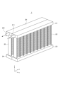
- FIG. 1 is a perspective view showing the overall configuration of a heat exchanger according to a first embodiment.
- FIG. 2 is an exploded perspective view of the heat exchanger shown in FIG.
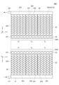
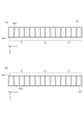
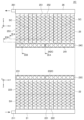
- FIG. 3 is a plan view showing the heat exchanger shown in FIG. 2 in a developed state.
- 4A and 4B are cross-sectional views showing the IVA-IVA section and the IVB-IVB section of FIG. 3, respectively.
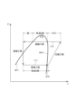
- FIG. 5 is a ph diagram showing the refrigeration cycle.
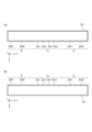
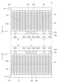
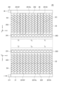
- FIG. 6 is a plan view showing the heat exchanger of the reference example in a developed state.
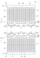
- FIG. 7 is a plan view showing the heat exchanger of the reference example in a developed state.
- FIG. 8A and 8B are cross-sectional views showing the cross-sectional structures of the first turn tank and the second turn tank of the reference example.
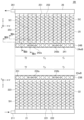
- FIG. 9 is a plan view showing a heat exchanger in a modified example of the first embodiment in a developed state.
- FIG. 10 is a plan view showing the heat exchanger according to the second embodiment in a developed state.
- FIG. 11 is a plan view showing a heat exchanger according to the third embodiment in a developed state.
- 12A and 12B are cross-sectional views taken along lines VIIIA-VIIIA and VIIIB-VIIIB in FIG. 11, respectively.
- FIG. 13 is a plan view showing a heat exchanger according to the fourth embodiment in a developed state.
- FIG. 14A and 14B are cross-sectional views taken along lines XA-XA and XB-XB in FIG. 13, respectively.
- FIG. 15 is a cross-sectional view showing a cross-sectional structure of a second turn tank of a heat exchanger according to the fourth embodiment.
- FIG. 16 is a plan view showing a heat exchanger according to the fifth embodiment in a developed state.
- FIG. 17 is a diagram showing an example of a tube used in the heat exchanger shown in FIG.
- FIG. 18 is a plan view showing a heat exchanger according to the sixth embodiment in a developed state.
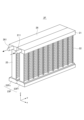
- FIG. 19 is a perspective view showing the overall configuration of a heat exchanger according to the seventh embodiment.
- FIG. 20 is a cross-sectional perspective view of the turn tank shown in FIG. 19.
- FIG. 21A and 21B are cross-sectional views taken along lines XVIA-XVIA and XVIB-XVIB in FIG. 20, respectively.
- FIG. 22 is a cross-sectional view showing a modification of FIG.
- FIG. 23 is a graph showing the relationship between Nsc/Nall and the left-right temperature difference ⁇ T of the air blown out from the heat exchanger.
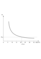
- FIG. 24 is a graph showing the relationship between the total opening area AS of the communication holes and the pressure loss PL of the refrigerant.
- the heat exchanger 2 includes a first header tank 21, a first core portion 22, a first turn tank 23, a second turn tank 24, a second core portion 25, and a second header tank 26.
- the heat exchanger 2 exchanges heat between a first fluid, air, and a second fluid, refrigerant.
- the heat exchanger 2 is used, for example, as a condenser for heating the interior of an automobile.
- the heat exchanger 2 as a condenser is incorporated into a refrigeration cycle (not shown).
- the heat exchanger 2 incorporated into the refrigeration cycle is connected to the upstream flow path and the downstream flow path of the refrigeration cycle.
- the first header tank 21 has an inlet 211.
- the inlet 211 is the portion into which the refrigerant, as the second fluid, flows from the upstream flow path of the refrigeration cycle.
- the refrigerant that flows into the inlet 211 flows into the first header tank 21.
- the refrigerant that flows into the first header tank 21 flows into the first core section 22.
- the refrigerant that flows into the first core section 22 flows into the first turn tank 23 while exchanging heat with the air, which is the first fluid.
- the refrigerant that flows into the first turn tank 23 flows into the second turn tank 24.
- the refrigerant that flows into the second turn tank 24 flows into the second core section 25.
- the refrigerant that flows into the second core section 25 flows into the second header tank 26 while exchanging heat with the first fluid, air.
- the second header tank 26 has an outlet 261.
- the outlet 261 is a portion through which the refrigerant flows into the downstream flow path of the refrigeration cycle.
- the refrigerant that flows into the second header tank 26 flows out from the outlet 261 into the downstream flow path.
- the direction in which air flows through the first core portion 22 and the second core portion 25 is the x-direction, and the x-axis is set along this direction.
- the y-direction is perpendicular to the x-direction, and is the longitudinal direction of the first header tank 21 and the second header tank 26, and the first turn tank 23 and the second turn tank 24, and the y-axis is set along this direction.
- the z-direction is perpendicular to both the x-direction and the y-direction, is a direction from the lower side to the upper side in FIG.
- the z-direction is a direction from the lower side to the upper side in FIG. 1, and the top and bottom of FIG. 1 do not necessarily have to match the top and bottom of the vertical direction. Therefore, when mounting the heat exchanger 2 on a vehicle, the first header tank 21 and the second header tank 26 may be positioned vertically downward, and the first turn tank 23 and the second turn tank 24 may be positioned vertically upward.
- FIG. 2 is an oblique view of the heat exchanger 2 shown in FIG. 1 in an expanded state to explain the inside.
- the first header tank 21, the first core portion 22, and the first turn tank 23 are shown rotated 90° around the z axis away from the second header tank 26, the second core portion 25, and the second turn tank 24.
- the x, y, and z axes for the first header tank 21, the first core portion 22, and the first turn tank 23 are shown in the vicinity of the first header tank 21, the first core portion 22, and the first turn tank 23.
- the x, y, and z axes for the second header tank 26, the second core portion 25, and the second turn tank 24 are shown in the vicinity of the second header tank 26, the second core portion 25, and the second turn tank 24.
- the first core portion 22 includes a first tube 221, a first fin 222, and a side plate 223.
- the first tube 221 is configured so that a second fluid, a refrigerant, flows through it.
- One end of the first tube 221 is connected to the first header tank 21, and the other end is connected to the first turn tank 23.
- a plurality of first tubes 221 are provided, and the first tubes 221 and the first fins 222 are stacked alternately.
- a pair of side plates 223 are provided so as to sandwich the stacked first tubes 221 and first fins 222 in the stacking direction.
- the first fin 222 is bent in a wavy shape.
- An air flow path is provided within the first fin 222, through which air, which is a first fluid, flows.
- a refrigerant flow path is provided within the first tube 221, through which a refrigerant, which is a second fluid, flows.
- the first fin 222 and the first tube 221 are in contact with each other, and are configured to be capable of heat exchange. Therefore, the air flowing through the first fin 222 and the refrigerant flowing through the first tube 221 are configured to be able to exchange heat.
- the first turn tank 23 has a partition wall 23w.
- the partition wall 23w is a wall that abuts against the second turn tank 24.
- the partition wall 23w has communication holes 23f1, 23f2, 23c1, 23c2, 23c3, 23c4, 23r1, and 23r2.
- the communication holes 23f1, 23f2, 23c1, 23c2, 23c3, 23c4, 23r1, and 23r2 are holes for passing the refrigerant.
- the communication holes 23f1, 23f2, 23c1, 23c2, 23c3, 23c4, 23r1, and 23r2 all have the same circular shape. Note that the communication holes 23f1, 23f2, 23c1, 23c2, 23c3, 23c4, 23r1, and 23r2 are all made to have the same circular shape for the sake of convenience of explanation, and the shape of the communication holes is not particularly limited and can be various shapes, including, for example, a semicircular shape or a rectangular shape.
- the communication holes 23f1, 23f2 are included in the second region Tf.
- the communication holes 23c1, 23c2, 23c3, 23c4 are included in the first region Tc.
- the communication holes 23r1, 23r2 are included in the second region Tr.
- the number of communication holes 23f1, 23f2 formed in one second region Tf is fewer than the number of communication holes 23c1, 23c2, 23c3, 23c4 formed in the first region Tc.
- the number of communication holes 23r1, 23r2 formed in one second region Tr is fewer than the number of communication holes 23c1, 23c2, 23c3, 23c4 formed in the first region Tc.
- the opening ratio of the first region Tc is higher than the opening ratio of the second region Tf, which is higher than the opening ratio of the second region Tr.
- the pressure loss of the second regions Tf and Tr is higher than the pressure loss of the first region Tc, and a pair of second regions Tf and Tr are provided with the first region Tc sandwiched between them.
- the second turn tank 24 has a partition wall 24w.
- the partition wall 24w is a wall that abuts against the first turn tank 23.
- the partition wall 24w is provided with communication holes 24f1, 24f2, 24c1, 24c2, 24c3, 24c4, 24r1, and 24r2.
- the communication holes 24f1, 24f2, 24c1, 24c2, 24c3, 24c4, 24r1, and 24r2 are holes for passing the refrigerant.
- the communication holes 24f1, 24f2, 24c1, 24c2, 24c3, 24c4, 24r1, and 24r2 all have the same circular shape.
- the communicating holes 24f1, 24f2 are included in the second region Tf.
- the communicating holes 24c1, 24c2, 24c3, 24c4 are included in the first region Tc.
- the communicating holes 24r1, 24r2 are included in the second region Tr.
- the number of communicating holes 24f1, 24f2 formed in one second region Tf is fewer than the number of communicating holes 24c1, 24c2, 24c3, 24c4 formed in the first region Tc.
- the number of communicating holes 24r1, 24r2 formed in one second region Tr is fewer than the number of communicating holes 24c1, 24c2, 24c3, 24c4 formed in the first region Tc.
- the opening ratio of the first region Tc is higher than the opening ratio of the second region Tf, which is higher than the opening ratio of the second region Tr.
- the pressure loss of the second regions Tf and Tr is higher than the pressure loss of the first region Tc, and a pair of second regions Tf and Tr are provided with the first region Tc sandwiched between them.
- the region in the second region Tf where the communication holes 23f1, 23f2, 24f1, and 24f2 are arranged is referred to as the "second outer region Tf1,” and the region other than the outer region Tf1 is referred to as the "second inner region Tf2.”
- the region in the second region Tr where the communication holes 23r1, 23r2, 24r1, and 24r2 are arranged is referred to as the "second outer region Tr1,” and the region other than the outer region Tr1 is referred to as the "second inner region Tr2.”
- the second inner regions Tf2 and Tr2 are respectively arranged between the second outer regions Tf1 and Tr1 and the first region Tc.
- the first region Tc is sandwiched between the second region Tf and the second region Tr.
- FIG. 3 is a plan view showing the perspective view of the heat exchanger 2 shown in FIG. 2, expanded into a plane.
- the x, y and z axes for the first header tank 21, the first core portion 22 and the first turn tank 23 are shown in the vicinity of the first header tank 21, the first core portion 22 and the first turn tank 23.
- the x, y and z axes for the second header tank 26, the second core portion 25 and the second turn tank 24 are shown in the vicinity of the second header tank 26, the second core portion 25 and the second turn tank 24.
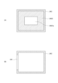
- FIG. 4(A) is a cross-sectional view showing the cross-sectional structure along IVA-IVA in FIG. 3.
- FIG. 4(B) is a cross-sectional view showing the cross-sectional structure along IVB-IVB in FIG. 3.
- the inside of the first turn tank 23 is connected in the y direction, which is its longitudinal direction.
- the inside of the second turn tank 24 is similarly connected in the y direction, which is its longitudinal direction.
- FIG. 5 is a diagram in which the refrigeration cycle is plotted on a ph diagram with enthalpy h on the horizontal axis and pressure p on the vertical axis.
- the portion to the left of critical point P10 is called the saturated liquid line M11
- the portion to the right of critical point P10 is called the saturated vapor line M12.
- the refrigeration cycle has a compression stroke, a condensation stroke, an expansion stroke, and an evaporation stroke.
- the compression stroke is a process in which the refrigerant gas evaporated in the evaporation stroke is compressed to produce high-temperature, high-pressure superheated gas refrigerant.
- the condensation stroke is a process in which heat is removed from the superheated gas refrigerant to produce supercooled liquid refrigerant.
- the expansion stroke is a process in which the pressure of the high-pressure supercooled liquid refrigerant is reduced.
- the evaporation stroke is a process in which heat is applied to the liquid refrigerant to cause it to evaporate.
- the evaporator is a heat exchanger used in the evaporation process of the refrigeration cycle shown in FIG. 5.
- the refrigerant in a two-phase gas-liquid state generated through the expansion process flows into the evaporator.
- the state of the refrigerant changes as shown by the arrow L11 due to heat exchange between the two-phase gas-liquid refrigerant and the air. That is, the two-phase gas-liquid refrigerant absorbs heat from the air and changes to a low-temperature, low-pressure gaseous refrigerant.
- the intersection of the arrow L11 and the saturated vapor line M12 indicates the point where the state of the refrigerant changes from the two-phase gas-liquid state to a gaseous state.
- the evaporator basically only has two states of the refrigerant: the two-phase gas-liquid state and the gaseous state. Therefore, when trying to uniformize the temperature distribution of the air blown out from the evaporator, it is generally sufficient to uniform the refrigerant flow rate in the region of the evaporator where the refrigerant in the gaseous state exists, the so-called superheated gas region.
- the heat exchanger 2 of this embodiment shown in Figures 1 to 4 functions as a condenser that performs a condensation process. Therefore, a high-temperature, high-pressure gaseous refrigerant generated through a compression process flows into the heat exchanger 2.
- the gaseous refrigerant exchanges heat with the air, causing the state of the refrigerant to change as shown by the arrow L12. That is, the gaseous refrigerant releases heat to the air, causing the state of the refrigerant to change sequentially to a gaseous state, a two-phase gas-liquid state, and a liquid state.
- the intersection of the arrow L12 and the saturated vapor line M12 indicates the point at which the state of the refrigerant changes from a gaseous state to a two-phase gas-liquid state.
- the process between the arrow L12 and the saturated liquid line M11 indicates the point at which the state of the refrigerant changes from a two-phase gas-liquid state to a liquid state.
- the heat exchanger 2 of this embodiment which functions as a condenser, has a reality that it is more difficult to uniformize the temperature distribution of the air than an evaporator.
- a superheated gas region is generated, for example as shown by the dashed line SH in FIG. 3.
- a gaseous refrigerant with a high flow rate flows into this superheated gas region SH through the inlet 211. Therefore, if a throttle or the like is provided in the first header tank 21 to adjust the refrigerant flow rate in the superheated gas region, there is a concern that the pressure loss of the gaseous refrigerant will increase. In this way, the inability to use a measure such as providing a throttle or the like in the first header tank 21 is also a factor that makes it difficult to uniform the temperature distribution of the air in the heat exchanger 2.
- the heat exchanger 200 of the reference example shown in Figures 6 and 7 has the same structure as the heat exchanger 2 shown in Figures 1 to 4, except that the communication holes 231 are evenly formed in the partition wall 23w of the first turn tank 23, and the communication holes 241 are evenly formed in the partition wall 24w of the second turn tank 24.
- elements similar to those of the heat exchanger 2 shown in Figures 1 to 4 are given the same reference numerals and redundant explanations will be omitted.
- the temperature distribution of the second core section 25, which is located upstream in the x-direction, which is the air flow direction, changes depending on the flow rate of the refrigerant.
- the flow rate of the refrigerant when the flow rate of the refrigerant is large, if the first header tank 21 shown in FIG. 6 is long in the y direction, the pressure loss of the refrigerant in the first header tank 21 becomes large. Therefore, in the first core portion 22, more refrigerant flows to shortcut the front region 224 located near the inlet 211, so the flow rate of the refrigerant flowing through the region 224 increases, while the flow rate of the refrigerant flowing through the opposite rear region 225 decreases. As a result, in the second core portion 25, the flow rate of the refrigerant flowing through the front region 254 increases, and the flow rate of the refrigerant flowing through the rear region 255 decreases.
- a supercooled liquid region SC10 is formed in the rear region 255 of the second core portion 25, and a temperature distribution is formed in the second core portion 25 in which the temperature of the rear region 255 is excessively low compared to the temperatures of the front region 254 and the intermediate region 256.
- the flow rate of the refrigerant is small, the pressure loss of the refrigerant in the first header tank 21 is small. Therefore, in the first core portion 22 shown in FIG. 7, the amount of refrigerant that flows in a shortcut through the front region 224 located near the inlet 211 is small, while inside the first header tank 21, the amount of refrigerant that flows to the back due to inertia is large. Therefore, in the first header tank 21, the flow rate of the refrigerant flowing through the intermediate region 226 is small compared to the front region 224 and the back region 225.
- the flow rate of the refrigerant flowing through the front region 254 and the back region 255 is large, and the flow rate of the refrigerant flowing through the intermediate region 256 is small. Therefore, a supercooled liquid region SC20 is formed in the intermediate region 256 of the second core portion 25, and a temperature distribution is formed in the second core portion 25 in which the temperature in the intermediate region 256 is excessively low compared to the temperatures in the front region 254 and the back region 255.
- the superheated gas refrigerant that flows into the first header tank 21 is distributed to the multiple first tubes 221 and flows toward the first turn tank 23.
- This flow creates a superheated gas region SH on the first header tank 21 side.
- the interiors of the turn tanks 23, 24 are connected in the y direction, which is their longitudinal direction. Therefore, when the refrigerant flows into the first turn tank 23 from the multiple first tubes 221, the refrigerant is more easily pressure-equalized inside the first turn tank 23.
- the flow rate of the refrigerant is controlled based on the arrangement of the communication holes formed in each turn tank 23, 24.
- the state of the refrigerant changes due to density changes.
- the heat exchanger 2 of this embodiment is configured so that the pressure loss in the second regions Tf and Tr is higher than the pressure loss in the first region Tc shown in FIG. 3.
- the refrigerant that flows into the first turn tank 23 flows into the second turn tank 24 through communication holes 23f1, 23f2, 23c1, 23c2, 23c3, 23c4, 23r1, 23r2 and communication holes 24f1, 24f2, 24c1, 24c2, 24c3, 24c4, 24r1, 24r2. Since the pressure loss in the second regions Tf and Tr is higher than the pressure loss in the first region Tc, the flow rate of the refrigerant flowing through the second regions Tf and Tr is relatively lower than the flow rate of the refrigerant flowing through the first region Tc, and a supercooled liquid region SC is formed. A pair of supercooled liquid regions SC are formed on either side of the first region Tc.
- the first region Tc corresponding to the communication holes 23c1, 23c2, 23c3, 23c4, 24c1, 24c2, 24c3, 24c4, the second outer region Tf1 corresponding to the communication holes 23f1, 23f2, 24f1, 24f2, and the second outer region Tr1 corresponding to the communication holes 23r1, 23r2, 24r1, 24r2 have a smaller pressure loss of the refrigerant compared to the second inner region Tf2, Tr2 in which no communication holes are formed. Therefore, the flow rate of the refrigerant in the second inner region Tf2, Tr2 is smaller than the flow rate of the refrigerant in the first region Tc, the second outer region Tf1, and the second outer region Tr1.
- a supercooled liquid region SC is formed in the parts of the second core portion 25 corresponding to the second inner regions Tf2, Tr2, respectively.
- the supercooled liquid region SC is intentionally formed in the second core portion 25 in the form shown in FIG. 3 by forming a communication hole in each turn tank 23, 24 as shown in FIG. 3 to control the flow rate of the refrigerant in the second core portion 25.
- the supercooled liquid region SC is easily formed in the second core portion 25 in the portion corresponding to the second inner region Tf2, Tr2 regardless of whether the flow rate of the refrigerant is high or low. In other words, a situation in which the position of the supercooled liquid region is shifted as shown in FIG. 6 and FIG.
- the refrigeration cycle is controlled so that the temperature of the refrigerant flowing out from the outlet 261 becomes the target temperature.
- the temperature distribution of the air blown out from the heat exchanger 200 is likely to deteriorate.
- the temperature of the middle region 256 may be excessively low compared to the temperatures of the front region 254 and the back region 255.
- the temperature of the refrigerant flowing out from the outlet 261 is the average temperature of the refrigerant that has passed through the front region 254, the back region 255, and the middle region 256 of the second core portion 25. Therefore, even if the target temperature of the refrigerant flowing out from the outlet 261 is controlled to 40 degrees, for example, in the second core portion 25 of the heat exchanger 200 of the reference example shown in FIG. 7, when the temperatures of the front region 254 and the back region 255 are each about 50 degrees, the temperature of the middle region 256 may indicate about 30 degrees.
- the temperature distribution of the second core section 25 is more easily uniformed than in the heat exchanger 200 of the reference example shown in Figures 6 and 7. Therefore, even if the temperature of the refrigerant flowing out of the outlet 261 is controlled to a target temperature, an area with a large temperature difference is less likely to occur in the second core section 25.
- the temperature of the supercooled liquid area SC shown in Figure 3 is approximately 38 degrees, and the temperature of the other areas is approximately 40 degrees. In this way, in the heat exchanger 2 of this embodiment, the temperature distribution of the second core section 25 is more easily uniformed, and as a result, the temperature distribution of the air blown out of the heat exchanger 200 is also more easily uniformed.
- the inlet 211 when the inlet 211 is formed in the center of the first header tank 21, the inlet 211 is formed to extend in the z direction from the center of the first header tank 21.
- the outlet 261 when the outlet 261 is formed in the center of the second header tank 26, the outlet 261 is formed to extend in the z direction from the center of the second header tank 26.
- an inlet 211 is formed on the side of the first header tank 21, and an outlet 261 is formed on the side of the second header tank 26.
- piping can be connected to the inlet 211 and the outlet 261 in the y direction, i.e., horizontally, making it easier to manage the piping.
- a structure such as the heat exchanger 2 of this embodiment, it is possible to flow the refrigerant in a downflow manner.
- the heat exchanger 2 of this embodiment has a one-pass structure with one-turn, in which the refrigerant flows in one direction in the first core portion 22 and the second core portion 25.
- the flow path cross-sectional area can be made larger compared to, for example, a heat exchanger in which the refrigerant flows in the first core portion 22 and the second core portion 25, making it possible to reduce the pressure loss of the refrigerant.
- a method that does not require consideration of the pressure loss of the refrigerant there is also a method of creating a branch bypass that does not pass through this heat exchanger 2 when cooling the battery, but in that case, it is difficult to adopt due to the high costs.
- FIG. 9 shows a modified example of the heat exchanger 2.
- only communication holes 23f1, 24f1 are formed in the second region Tf.
- the number of communication holes in the second region Tf is smaller than the number of communication holes in the second region Tr.
- the number of communication holes in the second region Tr is smaller than the number of communication holes in the first region Tc.
- Figure 10 is a plan view equivalent to Figure 3, showing the heat exchanger 2A.
- the first turn tank 23 and the second turn tank 24 of the heat exchanger 2 are changed to a first turn tank 23A and a second turn tank 24A.
- the first turn tank 23A has a partition wall 23wA.
- the partition wall 23wA is a wall that abuts against the second turn tank 24A.
- the partition wall 23wA is provided with communication holes 23f1A, 23f2A, 23f3A, 23f4A, 23c1A, 23c2A, 23r1A, 23r2A, 23r3A, and 23r4A.
- the communication holes 23f1A, 23f2A, 23f3A, 23f4A, 23c1A, 23c2A, 23r1A, 23r2A, 23r3A, and 23r4A are holes for passing the refrigerant.
- the communication holes 23f1A, 23f2A, 23f3A, 23f4A, 23r1A, 23r2A, 23r3A, and 23r4A all have the same circular shape.
- the communication holes 23c1A and 23c2A are openings with a larger area than the communication holes 23f1A, 23f2A, 23f3A, 23f4A, 23r1A, 23r2A, 23r3A, and 23r4A, and have, for example, an elliptical shape.
- the communication holes 23f1A, 23f2A, 23f3A, 23f4A, 23r1A, 23r2A, 23r3A, and 23r4A are all made to have the same circular shape for the sake of convenience of explanation, and the shape of the communication holes is not particularly limited and can be various shapes including, for example, a semicircular shape or a rectangular shape.
- communication holes 23c1A and 23c2A may be openings with a larger area than communication holes 23f1A, 23f2A, 23f3A, 23f4A, 23r1A, 23r2A, 23r3A, and 23r4A, and the elliptical shape is only one example of the shape, and various shapes including semi-elliptical and rectangular shapes are possible.
- the communication holes 23f1A, 23f2A, 23f3A, and 23f4A are included in the second region Tf.
- the communication holes 23c1A and 23c2A are included in the first region Tc.
- the communication holes 23r1A, 23r2A, 23r3A, and 23r4A are included in the second region Tr.
- the total opening area of the communication holes 23f1A, 23f2A, 23f3A, and 23f4A formed in one second region Tf is smaller than the total opening area of the communication holes 23c1A and 23c2A formed in the first region Tc.
- the total opening area of the communication holes 23r1A, 23r2A, 23r3A, and 23r4A formed in one second region Tr is smaller than the total opening area of the communication holes 23c1A and 23c2A formed in the first region Tc.
- the opening ratio of the first region Tc is higher than the opening ratio of the second region Tf, which is higher than the opening ratio of the second region Tr.
- the pressure loss of the second regions Tf and Tr is higher than the pressure loss of the first region Tc, and a pair of second regions Tf and Tr are provided with the first region Tc sandwiched between them.
- the second turn tank 24A has a partition wall 24wA.
- the partition wall 24wA is a wall that abuts the second turn tank 24A.
- the partition wall 24wA is provided with communication holes 24f1A, 24f2A, 24f3A, 24f4A, 24c1A, 24c2A, 24r1A, 24r2A, 24r3A, and 24r4A.
- the communication holes 24f1A, 24f2A, 24f3A, 24f4A, 24c1A, 24c2A, 24r1A, 24r2A, 24r3A, and 24r4A are holes for passing the refrigerant.
- the communication holes 24f1A, 24f2A, 24f3A, 24f4A, 24r1A, 24r2A, 24r3A, and 24r4A all have the same circular shape.
- the communication holes 24c1A and 24c2A are openings with a larger area than the communication holes 24f1A, 24f2A, 24f3A, 24f4A, 24r1A, 24r2A, 24r3A, and 24r4A, and have, for example, an elliptical shape.
- the communication holes 24f1A, 24f2A, 24f3A, and 24f4A are included in the second region Tf.
- the communication holes 24c1A and 24c2A are included in the first region Tc.
- the communication holes 24r1A, 24r2A, 24r3A, and 24r4A are included in the second region Tr.
- the total opening area of the communication holes 24f1A, 24f2A, 24f3A, and 24f4A formed in one second region Tf is smaller than the total opening area of the communication holes 24c1A and 24c2A formed in the first region Tc.
- the total opening area of the communication holes 24r1A, 24r2A, 24r3A, and 24r4A formed in one second region Tr is smaller than the total opening area of the communication holes 24c1A and 24c2A formed in the first region Tc.
- the opening ratio of the first region Tc is higher than the opening ratio of the second region Tf, which is higher than the opening ratio of the second region Tr.
- the pressure loss of the second regions Tf and Tr is higher than the pressure loss of the first region Tc, and a pair of second regions Tf and Tr are provided with the first region Tc sandwiched between them.
- the superheated gas refrigerant that flows into the first header tank 21 is distributed to multiple first tubes 221 and flows toward the first turn tank 23A. This flow creates a superheated gas region SH on the first header tank 21 side.
- the refrigerant that flows into the first turn tank 23A flows into the second turn tank 24A through the communication holes 23f1A, 23f2A, 23f3A, 23f4A, 23c1A, 23c2A, 23r1A, 23r2A, 23r3A, 23r4A and the communication holes 24f1A, 24f2A, 24f3A, 24f4A, 24c1A, 24c2A, 24r1A, 24r2A, 24r3A, 24r4A.
- the flow rate of the refrigerant flowing through the second regions Tf and Tr is relatively lower than the flow rate of the refrigerant flowing through the first region Tc, and a supercooled liquid region SC is formed.
- a pair of supercooled liquid regions SC are formed on either side of the first region Tc.
- Figure 11 is a plan view equivalent to Figure 3, showing the heat exchanger 2B.
- the first turn tank 23 and the second turn tank 24 of the heat exchanger 2 are changed to a first turn tank 23B and a second turn tank 24B.
- the first turn tank 23B has a partition wall 23wB.
- the partition wall 23wB is a wall that abuts against the second turn tank 24B.
- the partition wall 23wB has communication holes 231.
- 14 communication holes 231 are provided.
- the communication holes 231 are holes for passing the refrigerant. All of the communication holes 231 have the same circular shape.
- the communication holes 231 are all made to have the same circular shape for the sake of convenience of explanation, and the shape of the communication holes is not particularly limited and can be various shapes including, for example, a semicircular shape or a rectangular shape.
- the opening ratio of the first region Tc is the same as the opening ratio of the second region Tf, and the opening ratio of the first region Tc is the same as the opening ratio of the second region Tr.
- the first turn tank 23B has a protrusion 232a and a protrusion 232b.
- the protrusion 232a is provided in the second region Tf.
- the protrusion 232b is provided in the second region Tr.
- the second turn tank 24B has a partition wall 24wB.
- the partition wall 24wB is a wall that abuts against the second turn tank 24B.
- the partition wall 24wB has communication holes 241.
- 14 communication holes 241 are provided.
- the communication holes 241 are holes for passing the refrigerant. All of the communication holes 241 have the same circular shape.
- the opening ratio of the first region Tc is the same as the opening ratio of the second region Tf
- the opening ratio of the first region Tc is the same as the opening ratio of the second region Tr.
- the second turn tank 24B has a protrusion 242a and a protrusion 242b.
- the protrusion 242a is provided in the second region Tf.
- the protrusion 242b is provided in the second region Tr.
- FIG. 12(B) The VIIIA-VIIIA cross section of the second turn tank 24B in FIG. 11 is shown in FIG. 12(A).
- FIG. 12(B) The VIIIB-VIIIB cross section of the second turn tank 24B in FIG. 11 is shown in FIG. 12(B).
- the convex portion 242a locally narrows the internal volume of the second turn tank 24B.
- the pressure loss in the second regions Tf, Tr is higher than the pressure loss in the first region Tc, and a pair of second regions Tf, Tr are provided on either side of the first region Tc.
- the refrigerant that flows into the first turn tank 23B flows into the second turn tank 24B through the communication holes 231 and 241. Since the pressure loss in the second regions Tf and Tr, which are provided with the convex portions 232a, 232b, 242a, and 242b, is configured to be higher than the pressure loss in the first region Tc, the flow rate of the refrigerant flowing through the second regions Tf and Tr is relatively lower than the flow rate of the refrigerant flowing through the first region Tc, and a supercooled liquid region SC is formed. A pair of supercooled liquid regions SC are formed on either side of the first region Tc.
- Figure 13 is a plan view equivalent to Figure 3, showing the heat exchanger 2C.
- the first turn tank 23 and the second turn tank 24 of the heat exchanger 2 are changed to a first turn tank 23C and a second turn tank 24C.
- the first turn tank 23C is provided with a throttle portion 232C in place of the convex portions 232a and 232b of the first turn tank 23B described with reference to FIG. 11.
- the second turn tank 24C is provided with a throttle portion 242C in place of the convex portions 242a and 242b of the second turn tank 24B described with reference to FIG. 11.
- the XA-XA cross section of the second turn tank 24B in Figure 13 is shown in Figure 14(A).
- the XB-XB cross section of the second turn tank 24B in Figure 13 is shown in Figure 14(B).
- the constriction portion 242C is a flat plate-shaped member perpendicular to the y direction, and has a through hole 242Ca in its center.
- the constriction portion 242C locally narrows the internal volume of the second turn tank 24B.
- the superheated gas refrigerant that flows into the first header tank 21 is distributed to the multiple first tubes 221 and flows toward the first turn tank 23C. Due to this flow, a superheated gas region SH is formed on the first header tank 21 side.
- the refrigerant that flows into the first turn tank 23C flows into the second turn tank 24C through the communication holes 231 and 241. Because the throttle sections 232C and 242C are provided, the flow rate of the refrigerant flowing through the second regions Tf and Tr is relatively lower than the flow rate of the refrigerant flowing through the first region Tc, and a supercooled liquid region SC is formed. A pair of supercooled liquid regions SC are formed on either side of the first region Tc.
- FIG. 16 is a plan view equivalent to FIG. 3, showing the heat exchanger 2D.
- the first turn tank 23 and the second turn tank 24 of the heat exchanger 2 are changed to a first turn tank 23D and a second turn tank 24D.
- the first tube 221 of the heat exchanger 2 is changed to a first tube 221Df, 221Dc, and 221Dr.
- the second tube 251 of the heat exchanger 2 is changed to a second tube 251Df, 251Dc, and 251Dr.
- the first turn tank 23D is the first turn tank 23B described with reference to FIG. 11 with the protrusions 232a and 232b removed.
- the second turn tank 24D is the second turn tank 24B described with reference to FIG. 11 with the protrusions 242a and 242b removed.
- the first tube 221Df and the second tube 251Df are provided in the second region Tf.
- the first tube 221Dc and the second tube 251Dc are provided in the first region Tc.
- the first tube 221Dr and the second tube 251Dr are provided in the second region Tr.
- the internal flow path of the first tube 221Df is narrower than the internal flow path of the first tube 221Dc.
- the internal flow path of the first tube 221Dr is narrower than the internal flow path of the first tube 221Dc.
- the internal flow path of the second tube 251Df is narrower than the internal flow path of the second tube 251Dc.
- the internal flow path of the second tube 251Dr is narrower than the internal flow path of the second tube 251Dc.
- FIG. 17 shows four examples of how the internal flow paths of the first tubes 221Df, 221Dc, and 221Dr and the second tubes 251Df, 251Dc, and 251Dr are formed.
- Examples 1 and 2 are examples of tubes formed by extrusion molding.
- the internal flow paths of the first tube 221Dc and the second tube 251Dc have the same shape.
- the internal flow paths of the first tube 221Df and the second tube 251Df also have the same shape, and are narrower than the internal flow paths of the first tube 221Dc and the second tube 251Dc.
- the internal flow paths of the first tube 221Dr and the second tube 251Dr also have the same shape, and are narrower than the internal flow paths of the first tube 221Dc and the second tube 251Dc.
- Example 2 the internal flow paths of the first tube 221Dc and the second tube 251Dc are also the same shape as each other.
- the internal flow paths of the first tube 221Df and the second tube 251Df are arranged such that the one having the same shape as the internal flow path of the first tube 221Dc and the second tube 251Dc is arranged in the center, and those narrower than the internal flow paths of the first tube 221Dc and the second tube 251Dc are arranged on both sides.
- the internal flow paths of the first tube 221Dr and the second tube 251Dr are arranged such that the one having the same shape as the internal flow path of the first tube 221Dc and the second tube 251Dc is arranged in the center, and those narrower than the internal flow paths of the first tube 221Dc and the second tube 251Dc are arranged on both sides.
- Examples 3 and 4 are examples of inner fin type tubes.
- the pitch of the inner fins of the first tube 221Dc and the second tube 251Dc is equal.
- the pitch of the inner fins of the first tube 221Df and the second tube 251Df is also equal and is narrower than the pitch of the inner fins of the first tube 221Dc and the second tube 251Dc. Therefore, the internal flow path of the first tube 221Df and the second tube 251Df is narrower than the internal flow path of the first tube 221Dc and the second tube 251Dc. Similarly, the internal flow path of the first tube 221Dr and the second tube 251Dr is narrower than the internal flow path of the first tube 221Dc and the second tube 251Dc.
- Example 4 the pitch of the inner fins of the first tube 221Dc and the second tube 251Dc is also equal.
- the inner fins of the first tube 221Df and the second tube 251Df are arranged in the center with the same shape as the inner fins of the first tube 221Dc and the second tube 251Dc, and the inner fins with a narrower pitch than the inner fins of the first tube 221Dc and the second tube 251Dc are arranged on both sides. Therefore, the internal flow path of the first tube 221Df and the second tube 251Df is narrower than the internal flow path of the first tube 221Dc and the second tube 251Dc.
- the internal flow path of the first tube 221Dr and the second tube 251Dr is also narrower than the internal flow path of the first tube 221Dc and the second tube 251Dc.
- the superheated gas refrigerant that flows into the first header tank 21 is distributed to the first tubes 221Df, 221Dc, 221Dr and flows toward the first turn tank 23D. This flow forms a superheated gas region SH on the first header tank 21 side.
- the refrigerant that flows into the first turn tank 23D passes through the communication holes 231 and 241 and flows into the second turn tank 24D.
- the refrigerant that flows into the second turn tank 24D is distributed to the second tubes 251Df, 251Dc, and 251Dr and flows toward the second header tank 26.
- the internal flow path of the first tubes 221Df, 221Dr is narrower than the internal flow path of the first tube 221Dc, and the internal flow path of the second tubes 251Df, 251Dr is narrower than the internal flow path of the second tube 251Dc. Therefore, the flow rate of the refrigerant flowing through the second regions Tf, Tr is relatively smaller than the flow rate of the refrigerant flowing through the first region Tc, and a supercooled liquid region SC is formed. A pair of supercooled liquid regions SC are formed on either side of the first region Tc.
- FIG. 18 is a plan view equivalent to Figure 3, showing a heat exchanger 2E.
- the first turn tank 23 and the second turn tank 24 of the heat exchanger 2 are replaced with a first turn tank 23D and a second turn tank 24D.
- the first turn tank 23D and the second turn tank 24D have already been described with reference to Figure 16, so their description will be omitted.
- Heat exchanger 2E is a heat exchanger 2 in which the spacing between the first tube 221 and the second tube 251 is changed.
- the spacing between the first tube 221 and the second tube 251 arranged in the first region Tc is narrower than the spacing between the first tube 221 and the second tube 251 arranged in the second region Tf, Tr.
- the spacing between the first tube 221 and the second tube 251 arranged in the second region Tf, Tr is wider than the spacing between the first tube 221 and the second tube 251 arranged in the first region Tc.
- the width in the y-axis direction of the first fin 222Ec and the second fin 252Ec arranged in the first region Tc is narrower than the width in the y-axis direction of the first fins 222Ef, 222Er and the second fins 252Ef, 252Er arranged in the second regions Tf, Tr.
- the superheated gas refrigerant that flows into the first header tank 21 is distributed to multiple first tubes 221 and flows toward the first turn tank 23D. This flow creates a superheated gas region SH on the first header tank 21 side.
- the refrigerant that flows into the first turn tank 23D passes through the communication holes 231 and 241 and flows into the second turn tank 24D.
- the refrigerant that flows into the second turn tank 24D is distributed to the second tubes 251 and flows toward the second header tank 26.
- the spacing between the first tubes 221 provided in the second regions Tf, Tr is wider than the spacing between the first tubes 221 provided in the first region Tc, and the spacing between the second tubes 251 provided in the second regions Tf, Tr is wider than the spacing between the second tubes 251 provided in the first region Tc. Therefore, the flow rate of the refrigerant flowing through the second regions Tf, Tr is relatively lower than the flow rate of the refrigerant flowing through the first region Tc, and a supercooled liquid region SC is formed. A pair of supercooled liquid regions SC are formed on either side of the first region Tc.
- Figure 19 is a perspective view equivalent to Figure 1, showing the heat exchanger 2F.
- the heat exchanger 2F replaces the first turn tank 23 and the second turn tank 24 of the heat exchanger 2 with a single turn tank 23F.
- the turn tank 23F has a first turn tank portion 23Ff and a second turn tank portion 23Fs.
- the first turn tank portion 23Ff corresponds to the first turn tank 23.
- the second turn tank portion 23Fs corresponds to the second turn tank 24.
- the turn tank 23F is a turn tank that integrates the first turn tank portion 23Ff and the second turn tank portion 23Fs.
- the turn tank 23F has a communication part that connects the first turn tank part 23Ff and the second turn tank part 23Fs and allows the refrigerant to flow.
- Figure 20 is an oblique view including a cross-sectional view of a part where the communication part 231F is not provided.
- the turn tank 23F is formed by combining a first portion 23Fa and a second portion 23Fb.
- the first portion 23Fa has a joint portion 23Fa1, a wall portion 23Fa2, a wall portion 23Fa3, a wall portion 23Fa4, and a wall portion 23Fa5.
- the joint 23Fa1 and the walls 23Fa2 and 23Fa3 are flat plates extending in the y direction and are arranged to include the xy plane.
- the walls 23Fa2 and 23Fa3 are arranged to sandwich the joint 23Fa1 in the x direction.
- the walls 23Fa2 and 23Fa3 are arranged away from the joint 23Fa1 on the negative side of the z direction.
- the walls 23Fa4 and 23Fa5 are flat plates extending in the y direction and are arranged to include the yz plane.
- the wall 23Fa4 is connected to the wall 23Fa2 on the side opposite the joint 23Fa1.
- the wall 23Fa5 is connected to the wall 23Fa3 on the side opposite the joint 23Fa1.
- the second portion 23Fb has a joint portion 23Fb1, a wall portion 23Fb2, a wall portion 23Fb3, a wall portion 23Fb4, and a wall portion 23Fb5.
- the joint 23Fb1 and the walls 23Fb2 and 23Fb3 are flat plates extending in the y direction and are arranged to include the xy plane.
- the walls 23Fb2 and 23Fb3 are arranged to sandwich the joint 23Fb1 in the x direction.
- the walls 23Fb2 and 23Fb3 are arranged away from the joint 23Fb1 on the positive side of the z direction.
- Walls 23Fb4 and 23Fb5 are flat plates extending in the y direction and are arranged to include the yz plane.
- Wall 23Fb4 is connected to wall 23Fb2 on the side opposite joint 23Fb1.
- Wall 23Fb5 is connected to wall 23Fb3 on the side opposite joint 23Fb1.
- the turn tank 23F is formed.
- the first turn tank portion 23Ff is formed mainly by the walls 23Fa3, 23Fa5, 23Fb3, and 23Fb5.
- the second turn tank portion 23Fs is formed mainly by the walls 23Fa2, 23Fa4, 23Fb2, and 23Fb4.
- a plurality of communication portions 231F are provided to connect the first turn tank portion 23Ff and the second turn tank portion 23Fs.
- the XVIA-XVIA cross section of the communication part 231F in FIG. 20 is shown in FIG. 21(A).
- the XVIA-XVIA cross section is a cross section in the zx plane passing through the line XVIA-XVIA.
- the XVIB-XVIB cross section of the communication part 231F in FIG. 20 is shown in FIG. 21(B).
- the XVIB-XVIB cross section is a cross section in the yz plane passing through the line XVIB-XVIB.
- the communication part 231F has an outer shell part 231Fa.
- the outer shell part 231Fa is semi-cylindrical.
- the outer shell part 231Fa forms a communication hole 231Fb between itself and the joint part 23Fa1.
- the communication hole 231Fb is provided to connect the first turn tank part 23Ff and the second turn tank part 23Fs.
- the arrangement of the communication holes 231Fb can be the same as the arrangement of the communication holes in the first to sixth embodiments described above.
- the first region Tc and the second regions Tf and Tr can be formed in the same manner.
- the cross-sectional area of the flow passage of the communication hole 231Fb can be narrowed by filling in part of the inside of the outer shell 231a.
- the manner in which the cross-sectional area of the flow passage is narrowed will be described with reference to FIG. 22.
- the outer shell 231Fa is pressed from above to form the outer shell 231FAa, thereby forming a narrowed communication hole 231FAb.
- the outer shell 231Fa is pressed from above and from the left and right to form the outer shell 231FBa, thereby further narrowing the communication hole 231FBb.
- the first region Tc and the second region Tf, Tr are provided, which have different pressure losses when the same flow rate of refrigerant flows, so that the flow rate of the refrigerant flowing through the first region Tc and the flow rate of the refrigerant flowing through the second region Tf, Tr can be adjusted.
- the first region Tc and the second region Tf, Tr are arranged side by side in the y-axis direction, which is the stacking direction of the multiple first tubes 221, 221Df, 221Dc, 221Dr and the second tubes 251, 251Df, 251Dc, 251Dr, so that the flow rate of the refrigerant can be adjusted in a direction intersecting the air flow direction.
- the flow rate of the refrigerant can be suppressed to promote heat exchange of the refrigerant, and a portion that becomes a supercooled liquid region can be formed in a desired location, so that a good temperature distribution can be maintained.
- heat exchangers 2, 2A, 2B, 2C, 2D, and 2E are used to heat the vehicle interior, even if the air flow rate is different between the left and right sides in the y-axis direction, a supercooled region can be formed in each, and the temperature distribution between the left and right sides can be maintained well.
- the flow rate of the refrigerant flowing through the second regions Tf and Tr is relatively reduced compared to the flow rate of the refrigerant flowing through the first region Tc, and a supercooled liquid region SC is formed.
- the supercooled liquid region SC is formed corresponding to the second regions Tf and Tr, and is formed in a pair with the first region Tc in between. For example, when the second region Tf is formed near the side where the refrigerant flows into the first header tank 21, even if the flow rate of the refrigerant flowing into the first header tank 21 is low, it is possible to prevent the refrigerant from flowing excessively toward the second region Tf side by a so-called shortcut.
- the second region Tr is formed on the side opposite the side where the refrigerant flows into the first header tank 21, it is possible to prevent the refrigerant from flowing excessively toward the second region Tr side even if the flow rate of the refrigerant flowing into the first header tank 21 is high.
- the pair of second regions Tf, Tr arranged with the first region Tc in between is just one example, and the second regions Tf, Tr can be arranged in any manner as long as they are arranged next to the first region Tc in the y-axis direction.
- the first region Tc and the second region Tf, Tr are provided in the first turn tank 23, 23A, 23B and/or the second turn tank 24, 24A, 24B, so that the first region Tc and the second region Tf, Tr can be easily formed without using special tubes.
- Appendix 4 A heat exchanger 2, 2A described in Appendix 3, in which a partition wall 23w, 23wA, 24w, 24wA is provided between the first turn tank 23, 23A and the second turn tank 24, 24A, and the first region Tc and the second region Tf, Tr are provided in the partition wall 23w, 23wA, 24w, 24wA.
- the first region Tc and the second regions Tf, Tr are provided in the partition walls 23w, 23wA, 24w, 24wA, so that the first region Tc and the second regions Tf, Tr can be easily provided by only processing the partition walls 23w, 23wA, 24w, 23wA.
- the first region Tc and the second region Tf, Tr can be easily formed by making the number of communication holes provided in the partition walls 23w, 24w different between the first region Tc and the second region Tf, Tr.
- the difference in the flow rate of the refrigerant can be adjusted by adjusting the number of communication holes provided in the partition walls 23w, 24w, so that the formation position and formation mode of the second region Tf, Tr relative to the first region Tc can be more easily adjusted.
- the outer end of the first region Tc is, in other words, the end of the first region Tc on the side of the second region Tf or the end of the first region Tc on the side of the second region Tr.
- the inner end of the second region Tf is, in other words, the end of the second region Tf on the side of the first region Tc or the end of the second region Tr on the side of the first region Tc.
- the graph shown in FIG. 23 shows the relationship between Nsc/Nall on the horizontal axis and the left-right temperature difference ⁇ T of the air blown out from the heat exchanger 2 on the vertical axis.
- the left-right temperature difference ⁇ T of the air blown out from the heat exchanger 2 is the difference between the temperature of the air blown out after heat exchange with the part of the heat exchanger 2 to the left of the center in the y direction and the temperature of the air blown out after heat exchange with the part of the heat exchanger 2 to the right of the center in the y direction, when the direction in the y direction shown in FIG. 3 is the right direction and the opposite direction is the left direction.
- the graph shown in FIG. 3 is the right direction and the opposite direction is the left direction.
- the solid line L20 indicates the case where the height of the core parts 22 and 25 in the z direction is small, and the dashed line L21 indicates the case where the height of the core parts 22 and 25 in the z direction is large.
- the left-right temperature difference ⁇ T of the heat exchanger 2 becomes equal to or less than the threshold value ⁇ Ta.
- the threshold value ⁇ Ta indicates the allowable difference between the temperature of the air blown into the vehicle through the heat exchanger 2 toward the driver's seat and the temperature of the air blown into the passenger seat.
- the left-right temperature difference ⁇ T of the heat exchanger 2 decreases rapidly, in other words, the left-right temperature difference ⁇ T of the heat exchanger 2 is improved.
- the graph shown in Fig. 24 shows the relationship between the total opening area AS of the communication holes 241 actually provided in the first region Tc and the second regions Tf, Tr on the horizontal axis and the refrigerant pressure loss PL on the horizontal axis.
- the refrigerant pressure loss PL can be made smaller than the threshold value PLa.
- the threshold value PLa is an allowable value of the refrigerant pressure loss that can ensure the cooling performance when cooling the battery of an electric vehicle using a refrigeration cycle that utilizes the heat exchanger 2 of this embodiment, for example.
- the first region Tc and the second region Tf, Tr can be easily formed by making the total area of the communication holes provided in the partition walls 23wA, 24wA different between the first region Tc and the second region Tf, Tr.
- the difference in the refrigerant flow rate can be adjusted by adjusting the total area of the communication holes provided in the partition walls 23wA, 24wA, the formation position and formation mode of the second regions Tf, Tr relative to the first region Tc can be more easily adjusted.
- the total area of the communication holes is the sum of the opening areas of the communication holes formed in that region.
- the difference in pressure loss is created by changing the internal cross-sectional area of the first turn tank 23B, 23C and/or the second turn tank 24B, 24C in the y-axis direction, so that the first region Tc and the second regions Tf, Tr can be easily formed.
- Appendix 12 A heat exchanger as described in Appendix 11, in which the internal flow paths of the first tubes 221Df, 221Dr and/or the second tubes 251Df, 251Dr arranged in the second regions Tf, Tr are narrower than the internal flow paths of the first tubes 221Dc and/or the second tubes 251Dc arranged in the first region Tc.
- the difference in pressure loss is created by making the internal flow paths of the tubes different, so the first region Tc and the second regions Tf and Tr can be formed by a simple method such as changing the tubes.
- Appendix 13 A heat exchanger as described in Appendix 11, in which the number of first tubes 221 and/or second tubes 251 arranged in the second regions Tf, Tr is less than the number of first tubes 221 and/or second tubes 251 arranged in the first region Tc.
- the first region Tc and the second regions Tf and Tr can be formed by using normal tubes without making any changes to the turn tank, and by using a simple method such as varying the number of tubes.
Landscapes
- Engineering & Computer Science (AREA)
- Physics & Mathematics (AREA)
- Thermal Sciences (AREA)
- Mechanical Engineering (AREA)
- General Engineering & Computer Science (AREA)
- Geometry (AREA)
- Heat-Exchange Devices With Radiators And Conduit Assemblies (AREA)
Priority Applications (2)
| Application Number | Priority Date | Filing Date | Title |
|---|---|---|---|
| CN202480018708.1A CN120936847A (zh) | 2023-03-16 | 2024-03-13 | 热交换器 |
| JP2025506907A JPWO2024190835A1 (OSRAM) | 2023-03-16 | 2024-03-13 |
Applications Claiming Priority (2)
| Application Number | Priority Date | Filing Date | Title |
|---|---|---|---|
| JP2023-041658 | 2023-03-16 | ||
| JP2023041658 | 2023-03-16 |
Publications (1)
| Publication Number | Publication Date |
|---|---|
| WO2024190835A1 true WO2024190835A1 (ja) | 2024-09-19 |
Family
ID=92755300
Family Applications (1)
| Application Number | Title | Priority Date | Filing Date |
|---|---|---|---|
| PCT/JP2024/009848 Pending WO2024190835A1 (ja) | 2023-03-16 | 2024-03-13 | 熱交換器 |
Country Status (3)
| Country | Link |
|---|---|
| JP (1) | JPWO2024190835A1 (OSRAM) |
| CN (1) | CN120936847A (OSRAM) |
| WO (1) | WO2024190835A1 (OSRAM) |
Citations (6)
| Publication number | Priority date | Publication date | Assignee | Title |
|---|---|---|---|---|
| JP2005156144A (ja) * | 2003-10-29 | 2005-06-16 | Showa Denko Kk | 熱交換器 |
| JP2006170598A (ja) * | 2004-05-11 | 2006-06-29 | Showa Denko Kk | 熱交換器 |
| JP2013002758A (ja) * | 2011-06-17 | 2013-01-07 | Denso Corp | 車両用冷却装置 |
| JP2013195029A (ja) * | 2012-03-22 | 2013-09-30 | Denso Corp | 冷媒蒸発器 |
| JP2014089012A (ja) * | 2012-10-31 | 2014-05-15 | Denso Corp | 冷媒蒸発器 |
| JP2014518370A (ja) * | 2011-06-28 | 2014-07-28 | ヴァレオ システム テルミク | 熱交換器、当該熱交換器を備えたハウジングおよび空気調和回路 |
-
2024
- 2024-03-13 CN CN202480018708.1A patent/CN120936847A/zh active Pending
- 2024-03-13 WO PCT/JP2024/009848 patent/WO2024190835A1/ja active Pending
- 2024-03-13 JP JP2025506907A patent/JPWO2024190835A1/ja active Pending
Patent Citations (6)
| Publication number | Priority date | Publication date | Assignee | Title |
|---|---|---|---|---|
| JP2005156144A (ja) * | 2003-10-29 | 2005-06-16 | Showa Denko Kk | 熱交換器 |
| JP2006170598A (ja) * | 2004-05-11 | 2006-06-29 | Showa Denko Kk | 熱交換器 |
| JP2013002758A (ja) * | 2011-06-17 | 2013-01-07 | Denso Corp | 車両用冷却装置 |
| JP2014518370A (ja) * | 2011-06-28 | 2014-07-28 | ヴァレオ システム テルミク | 熱交換器、当該熱交換器を備えたハウジングおよび空気調和回路 |
| JP2013195029A (ja) * | 2012-03-22 | 2013-09-30 | Denso Corp | 冷媒蒸発器 |
| JP2014089012A (ja) * | 2012-10-31 | 2014-05-15 | Denso Corp | 冷媒蒸発器 |
Also Published As
| Publication number | Publication date |
|---|---|
| JPWO2024190835A1 (OSRAM) | 2024-09-19 |
| CN120936847A (zh) | 2025-11-11 |
Similar Documents
| Publication | Publication Date | Title |
|---|---|---|
| US8176750B2 (en) | Heat exchanger | |
| CN101082470B (zh) | 热交换管和蒸发器 | |
| US7448436B2 (en) | Heat exchanger | |
| US6047769A (en) | Heat exchanger constructed by plural heat conductive plates | |
| JP3814917B2 (ja) | 積層型蒸発器 | |
| US20030188857A1 (en) | Heat exchanger for exchanging heat between internal fluid and external fluid and manufacturing method thereof | |
| WO2008041698A1 (en) | Heat exchanger | |
| KR101707079B1 (ko) | 증발기 | |
| US6431264B2 (en) | Heat exchanger with fluid-phase change | |
| CN101349488A (zh) | 蒸发器 | |
| JP6927353B1 (ja) | 熱交換器 | |
| US6923251B2 (en) | Layered evaporator for use in motor vehicle air conditioners or the like, layered heat exhanger for providing the evaporator, and refrigeration cycle system comprising the evaporator | |
| US7051796B2 (en) | Heat exchanger | |
| US20040035564A1 (en) | Stack type heat exhcanger | |
| US6098703A (en) | Lamination type heat exchanger having refrigerant passage divided by inner fin into subpassages | |
| JP7259287B2 (ja) | 熱交換器 | |
| WO2024190835A1 (ja) | 熱交換器 | |
| EP0935115B1 (en) | Heat exchanger constructed by plural heat conductive plates | |
| JP5674376B2 (ja) | エバポレータ | |
| KR20170011736A (ko) | 열교환기용 튜브 | |
| JP6738233B2 (ja) | 蓄冷エバポレータ | |
| JP7744884B2 (ja) | 熱交換器 | |
| JP2000055573A (ja) | 冷媒蒸発器 | |
| CN114341573B (zh) | 热交换器 | |
| JP7310655B2 (ja) | 熱交換器 |
Legal Events
| Date | Code | Title | Description |
|---|---|---|---|
| 121 | Ep: the epo has been informed by wipo that ep was designated in this application |
Ref document number: 24770940 Country of ref document: EP Kind code of ref document: A1 |
|
| ENP | Entry into the national phase |
Ref document number: 2025506907 Country of ref document: JP Kind code of ref document: A |
|
| WWE | Wipo information: entry into national phase |
Ref document number: 2025506907 Country of ref document: JP |
|
| WWE | Wipo information: entry into national phase |
Ref document number: 2024770940 Country of ref document: EP |
|
| NENP | Non-entry into the national phase |
Ref country code: DE |
|
| ENP | Entry into the national phase |
Ref document number: 2024770940 Country of ref document: EP Effective date: 20251016 |
|
| ENP | Entry into the national phase |
Ref document number: 2024770940 Country of ref document: EP Effective date: 20251016 |
|
| ENP | Entry into the national phase |
Ref document number: 2024770940 Country of ref document: EP Effective date: 20251016 |
|
| ENP | Entry into the national phase |
Ref document number: 2024770940 Country of ref document: EP Effective date: 20251016 |
|
| ENP | Entry into the national phase |
Ref document number: 2024770940 Country of ref document: EP Effective date: 20251016 |