WO2024190362A1 - ショックアブソーバ - Google Patents
ショックアブソーバ Download PDFInfo
- Publication number
- WO2024190362A1 WO2024190362A1 PCT/JP2024/006534 JP2024006534W WO2024190362A1 WO 2024190362 A1 WO2024190362 A1 WO 2024190362A1 JP 2024006534 W JP2024006534 W JP 2024006534W WO 2024190362 A1 WO2024190362 A1 WO 2024190362A1
- Authority
- WO
- WIPO (PCT)
- Prior art keywords
- cylinder
- piston
- chamber
- passage
- damping force
- Prior art date
- Legal status (The legal status is an assumption and is not a legal conclusion. Google has not performed a legal analysis and makes no representation as to the accuracy of the status listed.)
- Ceased
Links
Images




Classifications
-
- F—MECHANICAL ENGINEERING; LIGHTING; HEATING; WEAPONS; BLASTING
- F16—ENGINEERING ELEMENTS AND UNITS; GENERAL MEASURES FOR PRODUCING AND MAINTAINING EFFECTIVE FUNCTIONING OF MACHINES OR INSTALLATIONS; THERMAL INSULATION IN GENERAL
- F16F—SPRINGS; SHOCK-ABSORBERS; MEANS FOR DAMPING VIBRATION
- F16F9/00—Springs, vibration-dampers, shock-absorbers, or similarly-constructed movement-dampers using a fluid or the equivalent as damping medium
- F16F9/32—Details
- F16F9/50—Special means providing automatic damping adjustment, i.e. self-adjustment of damping by particular sliding movements of a valve element, other than flexions or displacement of valve discs; Special means providing self-adjustment of spring characteristics
- F16F9/516—Special means providing automatic damping adjustment, i.e. self-adjustment of damping by particular sliding movements of a valve element, other than flexions or displacement of valve discs; Special means providing self-adjustment of spring characteristics resulting in the damping effects during contraction being different from the damping effects during extension, i.e. responsive to the direction of movement
-
- F—MECHANICAL ENGINEERING; LIGHTING; HEATING; WEAPONS; BLASTING
- F16—ENGINEERING ELEMENTS AND UNITS; GENERAL MEASURES FOR PRODUCING AND MAINTAINING EFFECTIVE FUNCTIONING OF MACHINES OR INSTALLATIONS; THERMAL INSULATION IN GENERAL
- F16F—SPRINGS; SHOCK-ABSORBERS; MEANS FOR DAMPING VIBRATION
- F16F9/00—Springs, vibration-dampers, shock-absorbers, or similarly-constructed movement-dampers using a fluid or the equivalent as damping medium
- F16F9/10—Springs, vibration-dampers, shock-absorbers, or similarly-constructed movement-dampers using a fluid or the equivalent as damping medium using liquid only; using a fluid of which the nature is immaterial
- F16F9/14—Devices with one or more members, e.g. pistons, vanes, moving to and fro in chambers and using throttling effect
- F16F9/16—Devices with one or more members, e.g. pistons, vanes, moving to and fro in chambers and using throttling effect involving only straight-line movement of the effective parts
- F16F9/18—Devices with one or more members, e.g. pistons, vanes, moving to and fro in chambers and using throttling effect involving only straight-line movement of the effective parts with a closed cylinder and a piston separating two or more working spaces therein
- F16F9/185—Bitubular units
-
- F—MECHANICAL ENGINEERING; LIGHTING; HEATING; WEAPONS; BLASTING
- F16—ENGINEERING ELEMENTS AND UNITS; GENERAL MEASURES FOR PRODUCING AND MAINTAINING EFFECTIVE FUNCTIONING OF MACHINES OR INSTALLATIONS; THERMAL INSULATION IN GENERAL
- F16F—SPRINGS; SHOCK-ABSORBERS; MEANS FOR DAMPING VIBRATION
- F16F9/00—Springs, vibration-dampers, shock-absorbers, or similarly-constructed movement-dampers using a fluid or the equivalent as damping medium
- F16F9/32—Details
- F16F9/3207—Constructional features
- F16F9/3235—Constructional features of cylinders
-
- F—MECHANICAL ENGINEERING; LIGHTING; HEATING; WEAPONS; BLASTING
- F16—ENGINEERING ELEMENTS AND UNITS; GENERAL MEASURES FOR PRODUCING AND MAINTAINING EFFECTIVE FUNCTIONING OF MACHINES OR INSTALLATIONS; THERMAL INSULATION IN GENERAL
- F16F—SPRINGS; SHOCK-ABSORBERS; MEANS FOR DAMPING VIBRATION
- F16F9/00—Springs, vibration-dampers, shock-absorbers, or similarly-constructed movement-dampers using a fluid or the equivalent as damping medium
- F16F9/32—Details
- F16F9/34—Special valve constructions; Shape or construction of throttling passages
- F16F9/348—Throttling passages in the form of annular discs or other plate-like elements which may or may not have a spring action, operating in opposite directions or singly, e.g. annular discs positioned on top of the valve or piston body
- F16F9/3481—Throttling passages in the form of annular discs or other plate-like elements which may or may not have a spring action, operating in opposite directions or singly, e.g. annular discs positioned on top of the valve or piston body characterised by shape or construction of throttling passages in piston
-
- F—MECHANICAL ENGINEERING; LIGHTING; HEATING; WEAPONS; BLASTING
- F16—ENGINEERING ELEMENTS AND UNITS; GENERAL MEASURES FOR PRODUCING AND MAINTAINING EFFECTIVE FUNCTIONING OF MACHINES OR INSTALLATIONS; THERMAL INSULATION IN GENERAL
- F16F—SPRINGS; SHOCK-ABSORBERS; MEANS FOR DAMPING VIBRATION
- F16F9/00—Springs, vibration-dampers, shock-absorbers, or similarly-constructed movement-dampers using a fluid or the equivalent as damping medium
- F16F9/32—Details
- F16F9/48—Arrangements for providing different damping effects at different parts of the stroke
- F16F9/49—Stops limiting fluid passage, e.g. hydraulic stops or elastomeric elements inside the cylinder which contribute to changes in fluid damping
-
- F—MECHANICAL ENGINEERING; LIGHTING; HEATING; WEAPONS; BLASTING
- F16—ENGINEERING ELEMENTS AND UNITS; GENERAL MEASURES FOR PRODUCING AND MAINTAINING EFFECTIVE FUNCTIONING OF MACHINES OR INSTALLATIONS; THERMAL INSULATION IN GENERAL
- F16F—SPRINGS; SHOCK-ABSORBERS; MEANS FOR DAMPING VIBRATION
- F16F2232/00—Nature of movement
- F16F2232/08—Linear
Definitions
- the present invention relates to a shock absorber.
- This application claims priority to U.S. patent application Ser. No. 18/121,649, filed in the United States on March 15, 2023, the contents of which are incorporated herein by reference.
- shock absorbers that increase the damping force when the piston rod reaches a certain range on the limit side during the compression stroke when the piston rod is pushed into the tube (for example, see Patent Document 1 below).
- an object of the present invention is to provide a shock absorber that makes it possible to suppress an increase in costs.
- one embodiment of the shock absorber of the present invention comprises a tube whose inside is an inner chamber, a piston rod whose one axial end is disposed within the tube and whose other axial end is disposed outside the tube, a piston assembly connected to the piston rod at an intermediate position in the axial direction to divide the inner chamber into a first chamber on the other end side of the piston rod and a second chamber on the one end side and generate a damping force when the piston rod moves, and a damping force increasing mechanism that increases the damping force when the piston assembly moves toward the second chamber.
- the damping force increasing mechanism comprises a first cylinder connected to the one end side of the piston rod relative to the piston assembly, and a partition piston that enters the inside of the first cylinder when the piston assembly moves toward the second chamber and forms a partitioned chamber within the first cylinder.
- shock absorber of the present invention makes it possible to suppress increases in costs.
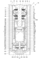
- FIG. 1 is a cross-sectional view showing a shock absorber according to a first embodiment of the present invention.
- 1 is a cross-sectional view of a main portion of a shock absorber according to a first embodiment of the present invention.
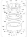
- FIG. 2 is a perspective view showing a base adapter of the shock absorber according to the first embodiment of the present invention.
- 1 is a cross-sectional view of a main portion of a shock absorber according to a first embodiment of the present invention.
- FIG. 6 is a cross-sectional view of a main portion of a shock absorber according to a second embodiment of the present invention.
- FIG. 11 is an exploded perspective view showing a compartment piston of a shock absorber according to a second embodiment of the present invention.
- FIG. 11 is a cross-sectional view of a main portion of a shock absorber according to a third embodiment of the present invention.
- FIG. 11 is a perspective cross-sectional view showing a movable ring support of a shock absorber according to a third embodiment of the present invention.
- FIG. 11 is a cross-sectional view of a main portion of a shock absorber according to a fourth embodiment of the present invention.
- FIG. 10 is an exploded perspective view showing a portion of a compartment piston of a shock absorber according to a fourth embodiment of the present invention.
- FIG. 13 is a cross-sectional view of a main portion of a shock absorber according to a fifth embodiment of the present invention.
- FIG. 13 is an exploded perspective cross-sectional view showing a body valve assembly of a shock absorber according to a fifth embodiment of the present invention.
- FIG. 13 is a cross-sectional view of a main portion of a shock absorber according to a sixth embodiment of the present invention.
- the shock absorber 1 of the first embodiment is a twin-tube hydraulic shock absorber.
- the shock absorber 1 is used in a suspension device for a vehicle, specifically an automobile.
- the shock absorber 1 is equipped with a cylinder 2.
- the cylinder 2 has a tube 3 and a shell 5.
- the tube 3 is cylindrical.
- the shell 5 is cylindrical with a bottom.
- the inner diameter of the shell 5 is larger than the outer diameter of the tube 3.
- the tube 3 is disposed radially inside the shell 5.
- the central axis of the tube 3 and the central axis of the shell 5 coincide.
- the inside of the tube 3 forms an inner chamber 6.
- the space between the tube 3 and the shell 5 forms a reservoir chamber 7.
- the shell 5 has a body member 11 and a bottom member 12.
- the body member 11 is cylindrical.
- the bottom member 12 is circular and is fitted inside the lower part of the body member 11. The entire circumference of the bottom member 12 is joined to the body member 11 by welding or the like.
- the bottom member 12 closes the lower part of the body member 11.
- the shock absorber 1 includes a piston assembly 17.
- the piston assembly 17 is disposed in the tube 3 of the cylinder 2.
- the piston assembly 17 includes a piston 18.
- the piston 18 of the piston assembly 17 is fitted slidably in the tube 3.
- the piston 18 divides the inner chamber 6 in the tube 3 into two chambers, a first chamber 19 on one side and a second chamber 20 on the other side.
- the first chamber 19 is located on the opposite side of the bottom member 12 from the piston 18.
- the second chamber 20 is located on the bottom member 12 side from the piston 18.
- oil L is sealed in the inner chamber 6 in the tube 3 as a working fluid.
- oil L and gas G are sealed in the reservoir chamber 7 between the tube 3 and the shell 5 as a working fluid.
- the shock absorber 1 includes a piston rod 21.
- the piston rod 21 has a first end 22, which is one end in the axial direction, disposed inside the tube 3 of the cylinder 2.
- the piston rod 21 has a second end 23, which is the other end in the axial direction, disposed outside the cylinder 2.
- the piston rod 21 is connected to a piston assembly 17 at a midpoint between the first end 22 and the second end 23 in the axial direction, the midpoint being closer to the first end 22.
- the piston rod 21 is connected to the piston assembly 17 and passes through the first chamber 19, extending outward from the tube 3 and the shell 5, i.e., the cylinder 2.
- the piston assembly 17 divides the inner chamber 6 into a first chamber 19 on the second end 23 side of the piston rod 21 in the axial direction, and a second chamber 20 on the first end 22 side.
- the shock absorber 1 is connected to the vehicle body with the portion of the piston rod 21 extending from the cylinder 2 located at the top. At the same time, the body member 11 of the shell 5 is located at the bottom and connected to the wheel side of the vehicle.
- the piston 18 is fixed to the piston rod 21. Therefore, the piston 18 and the piston rod 21 move together.
- the stroke in which the piston rod 21 moves in a direction to increase the amount of extension from the cylinder 2 is the extension stroke in which the overall length increases.
- the stroke in which the piston rod 21 moves in a direction to decrease the amount of extension from the cylinder 2 is the compression stroke in which the overall length contracts.
- the piston 18 moves towards the first chamber 19 during the extension stroke.
- the piston 18 moves towards the second chamber 20 during the compression stroke.
- a rod guide 25 is fitted to the upper opening side of the tube 3 and the upper opening side of the shell 5.
- a seal member 26 is fitted to the shell 5 above the rod guide 25. Both the rod guide 25 and the seal member 26 are annular.
- the piston rod 21 is inserted into the radial inside of each of the rod guide 25 and the seal member 26. The piston rod 21 slides along the axial direction of each of the rod guide 25 and the seal member 26. The piston rod 21 extends from inside the cylinder 2 to the outside of the cylinder 2 beyond the seal member 26.
- the rod guide 25 restricts the piston rod 21 from moving radially relative to the tube 3 and shell 5 of the cylinder 2.
- the piston rod 21 fits into the rod guide 25, and the piston 18 fits into the tube 3. This causes the central axis of the piston rod 21 to coincide with the central axis of the tube 3.
- the rod guide 25 supports the piston rod 21 so that it can move in the axial direction of the piston rod 21.
- the outer periphery of the seal member 26 is in close contact with the shell 5.
- the inner periphery of the seal member 26 is in close contact with the outer periphery of the piston rod 21.
- the piston rod 21 slides against the seal member 26 in the axial direction of the seal member 26.
- the seal member 26 prevents the oil liquid L in the tube 3 and the high-pressure gas G and oil liquid L in the reservoir chamber 7 from leaking out to the outside.
- the rod guide 25 has a large diameter section 28, an intermediate diameter section 29, and a small diameter section 30 on the outer periphery.
- the large diameter section 28 has an outer diameter larger than that of the intermediate diameter section 29.
- the intermediate diameter section 29 has an outer diameter larger than that of the small diameter section 30.
- the intermediate diameter section 29 of the rod guide 25 is provided below the large diameter section 28.
- the small diameter section 30 of the rod guide 25 is provided below the intermediate diameter section 29.
- the intermediate diameter section 29 of the rod guide 25 fits into the inner periphery of the upper end of the tube 3. At that time, the upper end of the tube 3 abuts against the large diameter section 28 in the axial direction of the tube 3.
- the upper large diameter section 28 of the rod guide 25 fits into the inner periphery of the upper part of the body member 11 of the shell 5.
- a body valve assembly 31 is placed on the bottom member 12 of the shell 5.
- the body valve assembly 31 is provided on the opposite side of the second chamber 20 from the piston assembly 17.
- the body valve assembly 31 has a seat member 32.
- the seat member 32 is placed in contact with the upper surface of the bottom member 12 of the shell 5.
- the seat member 32 is positioned radially relative to the shell 5.
- the seat member 32 has a large diameter portion 33 and a small diameter portion 34 on its radial outer periphery.
- the large diameter portion 33 has an outer diameter larger than the outer diameter of the small diameter portion 34.
- the large diameter portion 33 of the seat member 32 is provided below the small diameter portion 34.
- the large diameter portion 33 of the seat member 32 is placed on the upper surface of the bottom member 12.
- the seat member 32 fits into the inner periphery of the lower end of the tube 3 at the upper small diameter portion 34. At that time, the lower end of the tube 3 abuts against the large diameter portion 33 in the axial direction of the tube 3. This connects the body valve assembly 31 to one axial end of the tube 3.
- a cover 41 is attached to the upper end of the body member 11 of the shell 5.
- the cover 41 is fitted and fixed to the body member 11.
- a disk 42 is placed on the seal member 26, and the disk 42 and the seal member 26 are fixed to the cylinder 2 by being sandwiched between the cover 41 and the rod guide 25.
- the disk 42 is pressed against the seal member 26 along the axial direction of the shell 5 with the bottom member 12 of the shell 5 placed on a base. Then, the disk 42, the seal member 26, the rod guide 25, the tube 3, the sheet member 32, and the bottom member 12 abut against each other without any gaps in the axial direction. This generates an axial force in the disk 42, the seal member 26, the rod guide 25, the tube 3, and the sheet member 32.
- the cover 41 is fixed to the body member 11. Then, an axial force is generated in the disk 42, the seal member 26, the rod guide 25, the tube 3, and the sheet member 32.
- the piston rod 21 has a main shaft portion 51 and a mounting shaft portion 52. Both the main shaft portion 51 and the mounting shaft portion 52 are rod-shaped. The outer diameter of the mounting shaft portion 52 is smaller than the outer diameter of the main shaft portion 51. The mounting shaft portion 52 extends from one axial end of the main shaft portion 51. The central axis of the mounting shaft portion 52 coincides with the central axis of the main shaft portion 51. The entire mounting shaft portion 52 is disposed within the tube 3. The main shaft portion 51 of the piston rod 21 slides along the axial direction relative to the rod guide 25 and the seal member 26, respectively.
- the piston rod 21 has a first end 22 at the end opposite the main shaft 51 in the axial direction of the mounting shaft 52.
- a male thread 54 is formed on the outer periphery of the first end 22.
- the portion of the mounting shaft 52 between the main shaft 51 and the first end 22 in the axial direction of the mounting shaft 52 is an engagement shaft 55.
- the outer periphery of the engagement shaft 55 is a cylindrical surface.
- the piston rod 21 has a mounting shaft portion 52 to which the piston assembly 17, the intervening member 60, the intervening member 61, and the relief valve assembly 62 (valve assembly) are connected.
- the piston 18 of the piston assembly 17 has a through hole 70 formed in its radial center.
- the through hole 70 penetrates the piston 18 in the axial direction of the piston 18.
- the fitting shaft portion 55 of the piston rod 21 is fitted into the through hole 70 of the piston 18.
- the piston 18 has a first passage 71 and a second passage 72 formed outside the through hole 70 in the radial direction of the piston 18.
- the first passage 71 and the second passage 72 penetrate the piston 18 in the axial direction of the piston 18.
- the first passage 71 and the second passage 72 are formed in multiples in the piston 18.
- the first passages 71 and the second passages 72 are alternately arranged in the circumferential direction of the piston 18.
- the first passages 71 and the second passages 72 can both communicate with the first chamber 19 and the second chamber 20.
- the piston assembly 17 has a first damping valve 75 and a second damping valve 76.
- the first damping valve 75 is a disk valve formed by stacking a plurality of annular disks.
- the first damping valve 75 fits the mating shaft portion 55 of the piston rod 21 into its radial inside.
- the first damping valve 75 is arranged on the opposite side of the piston rod 21 from the main shaft portion 51 of the piston 18 in the axial direction of the piston rod 21.
- the outer peripheral portion of the first damping valve 75 separates from the piston 18 to open the first passage 71.
- the first damping valve 75 flows the oil L from the first chamber 19 to the second chamber 20 through the first passage 71. At that time, the first damping valve 75 suppresses the flow of the oil L to generate a damping force.
- the first damping valve 75 is provided in the first passage 71 and suppresses the flow of the oil L generated in the first passage 71 during the extension stroke to generate a damping force.
- the first damping valve 75 has an outer circumferential portion that abuts against the piston 18 to close the first passage 71.
- a fixed orifice (not shown) is provided between the first damping valve 75 and the piston 18. This fixed orifice allows oil L to flow from the first chamber 19 to the second chamber 20 through the first passage 71 even when the outer circumferential portion of the first damping valve 75 abuts against the piston 18.
- the second damping valve 76 is a disk valve formed by stacking a plurality of annular disks.
- the second damping valve 76 has the fitting shaft portion 55 fitted to its radial inside.
- the second damping valve 76 is disposed between the main shaft portion 51 and the piston 18 in the axial direction of the piston rod 21.
- the outer peripheral portion of the second damping valve 76 separates from the piston 18 to open the second passage 72.
- the second damping valve 76 flows the oil L from the second chamber 20 to the first chamber 19 through the second passage 72. At that time, the second damping valve 76 suppresses the flow of the oil L to generate a damping force.
- the second damping valve 76 is provided in the second passage 72, and suppresses the flow of the oil L generated in the second passage 72 during the compression stroke to generate a damping force.
- the outer peripheral portion of the second damping valve 76 abuts against the piston 18 to close the second passage 72.
- a fixed orifice (not shown) is provided between the second damping valve 76 and the piston 18. This fixed orifice allows oil L to flow from the second chamber 20 to the first chamber 19 through the second passage 72 even when the outer circumferential portion of the second damping valve 76 abuts against the piston 18.
- the piston assembly 17, which includes the piston 18, the first damping valve 75, and the second damping valve 76, moves integrally with the piston rod 21 when the piston rod 21 moves in the axial direction of the tube 3 relative to the tube 3, generating a damping force.
- the intervening member 60 is annular.
- the intervening member 60 has the mating shaft portion 55 fitted into its radially inner side.
- the intervening member 60 is disposed on the opposite side of the second damping valve 76 from the piston 18 in the axial direction of the piston rod 21.
- the intervening member 60 abuts against the second damping valve 76.
- the intervening member 60 has higher rigidity than the disk that constitutes the second damping valve 76.
- the intervening member 60 suppresses excessive deformation of the second damping valve 76.
- the intervening member 61 is annular.
- the intervening member 61 has the mating shaft portion 55 fitted into its radially inner side.
- the intervening member 61 is disposed on the opposite side of the first damping valve 75 from the piston 18 in the axial direction of the piston rod 21.
- the intervening member 61 abuts against the first damping valve 75.
- the intervening member 61 has higher rigidity than the disk that constitutes the first damping valve 75.
- the intervening member 61 suppresses excessive deformation of the first damping valve 75.
- the relief valve assembly 62 has a support piston 81 and a relief valve 82.
- the support piston 81 has a through hole 84 formed in its radial center.
- the through hole 84 passes through the support piston 81 in the axial direction of the support piston 81.
- the mating shaft portion 55 of the piston rod 21 is fitted into the through hole 84 of the support piston 81.
- the support piston 81 has a passage hole 85 formed outside the through hole 84 in the radial direction of the support piston 81.
- the passage hole 85 passes through the support piston 81 in the axial direction of the support piston 81.
- a plurality of passage holes 85 are formed in the support piston 81.
- the plurality of passage holes 85 are arranged at intervals in the circumferential direction of the support piston 81.
- the support piston 81 has a large diameter portion 87 and a small diameter portion 88 on its outer periphery.
- the large diameter portion 87 has an outer diameter larger than the outer diameter of the small diameter portion 88.
- the support piston 81 has the small diameter portion 88 located below the large diameter portion 87.
- the relief valve 82 is a disk valve formed by stacking multiple annular disks.
- the fitting shaft portion 55 of the piston rod 21 is fitted into the radial inside of the relief valve 82.
- the relief valve 82 is disposed between the intervening member 61 and the support piston 81 in the axial direction of the piston rod 21.
- the relief valve 82 has an outer peripheral portion that abuts against the support piston 81 to close the passages in the multiple passage holes 85.
- the relief valve 82 has an outer peripheral portion that separates from the support piston 81 to open the passages in the multiple passage holes 85.
- the intervening member 61 abuts against the relief valve 82.
- the intervening member 61 has a higher rigidity than the disks that constitute the relief valve 82.
- the intervening member 61 suppresses excessive deformation of the relief valve 82.
- the first end 22 of the piston rod 21 protrudes from the support piston 81 on the opposite side of the relief valve 82 in the axial direction of the piston rod 21.
- a nut 91 is screwed onto a male thread 54 formed on the outer periphery of the first end 22.
- the relief valve assembly 62 which includes the support piston 81 and the relief valve 82, is attached to the mounting shaft portion 52 of the piston rod 21 by a nut 91. Therefore, the relief valve assembly 62 is provided on the body valve assembly 31 side of the piston assembly 17 of the piston rod 21.
- the support piston 81 is fixed to the piston rod 21.
- the relief valve assembly 62 is connected to the piston rod 21 closer to the first end 22 than the piston assembly 17.
- the relief valve assembly 62 includes a support piston 81 connected to the piston rod 21 closer to the first end 22 than the piston assembly 17, and a relief valve 82 consisting of a plate-shaped disk that is provided in contact with the support piston 81.
- the support piston 81 is connected to a first cylinder 101.
- the support piston 81 and the first cylinder 101 form a cylindrical cup 100 with a bottom.
- the cup 100 moves together with the piston rod 21.
- the first cylinder 101 is cylindrical.
- the outer diameter of the first cylinder 101 is smaller than the inner diameter of the tube 3.
- the first cylinder 101 is disposed radially inside the tube 3.
- the small diameter portion 88 at the bottom of the support piston 81 is press-fitted into the inner periphery of the upper end of the first cylinder 101. This fixes the first cylinder 101 to the support piston 81.
- the upper end of the first cylinder 101 abuts against the large diameter portion 87 of the support piston 81 in the axial direction.
- the central axis of the first cylinder 101 and the central axis of the tube 3 coincide.
- the first cylinder 101 is disposed in the second chamber 20 with a radial gap between it and the tube 3.
- the first cylinder 101 is supported by the support piston 81.
- the first cylinder 101 has a main body portion 111 and an enlarged diameter portion 112 .
- the main body portion 111 is cylindrical with a constant inner diameter and a constant outer diameter, and is provided from one end to an intermediate portion in the axial direction of the first cylinder 101.
- One axial end of the main body portion 111 of the first cylinder 101 fits into the small diameter portion 88 of the support piston 81.
- the other end of the first cylinder 101 extends downward from the intermediate portion in the axial direction of the main body portion 111 from the support piston 81.
- the enlarged diameter portion 112 is provided at the other end, i.e., the lower end, of the first cylinder 101 in the axial direction.
- the inner diameter of the enlarged diameter portion 112 becomes larger as it approaches the lower end.
- the outer diameter of the enlarged diameter portion 112 becomes larger as it approaches the lower end.
- the enlarged diameter portion 112 enlarges in the axial direction of the first cylinder 101 in the direction away from the main body portion 111.
- the first cylinder 101 opens downward.
- the first cylinder 101 has a groove 116 extending in the axial direction of the first cylinder 101 on the inner periphery of one axial end side.
- the groove 116 is provided on the inner periphery of the lower end side of the first cylinder 101.
- the groove 116 is recessed outward in the radial direction of the first cylinder 101 from the inner periphery of the first cylinder 101.
- the groove 116 extends from the expanded diameter portion 112 to the lower part of the main body portion 111.
- the first cylinder 101 has a plurality of grooves 116 provided at equal intervals in the circumferential direction of the first cylinder 101.
- the grooves 116 each have a different length from the lower end of the first cylinder 101. In other words, the grooves 116 each have a different length in the axial direction of the first cylinder 101.
- the first cylinder 101 is connected to the piston rod 21 on the first end 22 side of the piston assembly 17 via the support piston 81 of the relief valve assembly 62.
- the relief valve assembly 62 is disposed in the second chamber 20 and connected to the piston rod 21.
- the body valve assembly 31 has a disk valve 122, a disk valve 123, a bolt 124, and a nut 125 in addition to the above-mentioned seat member 32.
- the bolt 124 has a shaft portion 126 and a head portion 127.
- the outer diameter of the shaft portion 126 is smaller than the outer diameter of the head portion 127.
- a male thread 128 is formed on the outer periphery of the shaft portion 126 on the axially opposite side to the head portion 127.
- the disk valve 122 is provided below the seat member 32.
- the disk valve 123 is provided above the seat member 32.
- the shaft 126 of the bolt 124 is inserted into the disk valve 122, seat member 32, and disk valve 123 from below.
- the nut 125 is screwed into the male thread 128 of the bolt 124. In this way, the bolt 124 and the nut 125 attach the disk valve 122 and disk valve 123 to the seat member 32.
- the seat member 32 has an annular shape.
- the seat member 32 has a base portion 131 and a protrusion portion 132.
- the base portion 131 is disk-shaped.
- a through hole 133 is formed in the radial center of the base portion 131.
- the through hole 133 penetrates the base portion 131 in the axial direction of the seat member 32.
- the shaft portion 126 of the bolt 124 is inserted into the through hole 133.
- a passage hole 134 and a passage hole 135 are formed outside the through hole 133 in the radial direction of the seat member 32.
- the passage hole 134 and the passage hole 135 penetrate the base portion 131 in the axial direction of the seat member 32.
- the passage hole 135 is located outside the passage hole 134 in the radial direction of the seat member 32.
- the sheet member 32 has multiple passage holes 134 and multiple passage holes 135 formed at intervals in the circumferential direction.
- the protrusion 132 protrudes downward from the outer periphery of the base portion 131.
- the protrusion 132 is disposed outside the passage hole 135 in the radial direction of the base portion 131.
- the protrusion 132 of the sheet member 32 abuts against the bottom member 12 of the shell 5.
- the protrusion 132 has a passage groove 136 formed therein, which penetrates the protrusion 132 in the radial direction of the sheet member 32.
- the sheet member 32 has a plurality of passage grooves 136 provided at equal intervals in the circumferential direction of the sheet member 32.
- the shock absorber 1 includes a base adapter 141, a second cylinder 142 (support member), and a partition piston 143.
- the base adapter 141 is annular.
- the base adapter 141 has a main plate portion 151, a press-fit portion 152, and legs 153.
- the main plate portion 151 is disk-shaped.
- the press-fit portion 152 is provided at one axial end of the base adapter 141.
- the press-fit portion 152 protrudes upward from the upper surface of the main plate portion 151.
- the press-fit portion 152 is cylindrical.
- the outer diameter of the press-fit portion 152 is smaller than the outer diameter of the main plate portion 151.
- a through hole 161 is formed in the radial center of the main plate portion 151 and the press-fit portion 152, penetrating them in the axial direction.
- the main plate portion 151 is disk-shaped with a hole
- the press-fit portion 152 is cylindrical.
- the leg portion 153 is provided at the end of the base adapter 141 opposite the press-fit portion 152 in the axial direction.
- the leg portion 153 protrudes downward from the underside of the outer periphery of the main plate portion 151.
- the leg portion 153 is cylindrical.
- the leg portion 153 is disposed outside the through hole 161 in the radial direction of the main plate portion 151.
- the radially inner inner periphery of the leg portion 153 becomes larger in diameter the further it is from the main plate portion 151 in the axial direction of the base adapter 141. In other words, the inner periphery of the leg portion 153 becomes larger in diameter the further it is from the main plate portion 151 in the axial direction.
- the outer periphery of the main plate portion 151 and the leg portion 153 are formed with a communication groove 162 that penetrates the main plate portion 151 and the leg portion 153 in the axial direction of the base adapter 141.
- the communication groove 162 opens to the outside in the radial direction of the base adapter 141.
- the communication groove 162 penetrates the leg portion 153 in the radial direction of the base adapter 141. Therefore, the communication groove 162 opens to the upper surface of the main plate portion 151, the outer periphery of the main plate portion 151, the outer periphery of the leg portion 153, the lower surface of the leg portion 153, and the inner periphery of the leg portion 153.
- the base adapter 141 is provided with a plurality of communication grooves 162 at equal intervals in the circumferential direction of the base adapter 141.
- the base adapter 141 is fixed by pressing the legs 153 into the inner circumference of the tube 3.
- the lower end of the legs 153 of the base adapter 141 abuts against the upper surface of the outer circumference of the base portion 131 of the seat member 32.
- the through hole 161 prevents the base adapter 141 from hitting the bolts 124 and nuts 125 of the body valve assembly 31.
- the legs 153 of the base adapter 141 surround the disk valve 123 of the body valve assembly 31 on the radial outside. In other words, the legs 153 are positioned radially outwardly of the disk valve 123 with respect to the disk valve 123.
- the base adapter 141 abutting against the body valve assembly 31 is provided between the first cylinder 101 and the body valve assembly 31.
- the base adapter 141 is supported in the axial direction by the body valve assembly 31 and in the radial direction by the tube 3.
- the second cylinder 142 is cylindrical.
- the outer diameter of the second cylinder 142 is smaller than the inner diameter of the main body portion 111 of the first cylinder 101.
- the press-in portion 152 of the base adapter 141 is pressed into the inner periphery of the lower end of the second cylinder 142.
- the upper surface of the main plate portion 151 abuts against the lower end of the second cylinder 142.
- the second cylinder 142 is pressed into and fixed to the base adapter 141.
- the second cylinder 142 extends from the base adapter 141 on the opposite side to the body valve assembly 31 in the axial direction of the base adapter 141.
- the base adapter 141 and the second cylinder 142 are provided in the second chamber 20.
- the second cylinder 142 is supported in the radial direction by the base adapter 141, and in the axial direction by the body valve assembly 31 via the base adapter 141.
- the communication groove 162 of the base adapter 141 is formed radially outward of the second cylinder 142 of the main plate portion 151.
- one axial end of the base adapter 141 is provided with a press-fit portion 152 that is press-fitted into the second cylinder 142.
- the other axial end of the base adapter 141 is provided with a leg portion 153 that is placed on the body valve assembly 31.
- the inner periphery of the leg portion 153 expands in diameter in the axial direction of the base adapter 141 as it approaches the body valve assembly 31.
- the partition piston 143 is attached to the end of the second cylinder 142 opposite the base adapter 141 in the axial direction, i.e., the upper end of the second cylinder 142.
- the partition piston 143 has a base member 171, a locking member 172, and a movable ring 173 (movable member).
- the base member 171 has a main body portion 181, a flange portion 182, and a cylindrical portion 183.
- the main body portion 181 is cylindrical.
- the flange portion 182 extends from one axial end side of the main body portion 181 to the outside in the radial direction of the main body portion 181.
- the flange portion 182 is annular and extends around the entire circumference of the main body portion 181.
- the outer diameter of the flange portion 182 is smaller than the inner diameter of the main body portion 111 of the first cylinder 101.
- Axial grooves 191 extending in the axial direction of the main body 181 are formed on the outer periphery of the main body 181, except for the flange portion 182.
- a plurality of axial grooves 191 are formed in the main body 181 at intervals in the circumferential direction.
- the flange portion 182 has radial grooves 192 formed on the axial groove 191 side in the axial direction, penetrating the flange portion 182 in the radial direction of the flange portion 182.
- the flange portion 182 has a plurality of radial grooves 192 formed at intervals in the circumferential direction.
- the flange portion 182 has the same number of radial grooves 192 as the axial grooves 191 in the main body portion 181.
- Each of the plurality of radial grooves 192 is aligned in phase with the corresponding axial groove 191 in the circumferential direction of the base member 171.
- the tubular portion 183 is cylindrical with an outer diameter smaller than the outer diameter of the flange portion 182.
- An axial groove 193 extending in the axial direction is formed on the outer periphery of the tubular portion 183.
- a plurality of axial grooves 193 are formed in the tubular portion 183 at intervals in the circumferential direction. In the axial direction of the tubular portion 183, the axial grooves 193 are formed so as to extend from the end of the tubular portion 183 on the flange portion 182 side in the axial direction to the opposite side to the flange portion 182.
- the locking member 172 has a fitting portion 201 and a flange portion 202 .
- the fitting portion 201 is cylindrical.
- the flange portion 202 spreads outward in the radial direction of the fitting portion 201 from one end side in the axial direction of the fitting portion 201.
- the flange portion 202 is annular and extends around the entire circumference of the fitting portion 201.
- the outer diameter of the flange portion 202 is smaller than the inner diameter of the main body portion 111 of the first cylinder 101.
- a passage hole 205 is formed in the flange portion 202, penetrating the flange portion 202 in the axial direction of the flange portion 202.
- a plurality of passage holes 205 are formed in the flange portion 202 at intervals in the circumferential direction.
- the movable ring 173 is annular. A portion of the movable ring 173 in the circumferential direction is broken to have a circumferential gap, which allows it to expand and contract in the radial direction.
- the movable ring 173 has an inner diameter in its natural state that is smaller than the outer diameter of the flange portion 182 of the base member 171 and the outer diameter of the flange portion 202 of the locking member 172.
- the movable ring 173 has an outer diameter in its natural state that is equal to or smaller than the maximum inner diameter of the expanded diameter portion 112 of the first cylinder 101 and larger than the inner diameter of the main body portion 111.
- the movable ring 173 contracts in diameter and its outer diameter becomes equal to the inner diameter of the main body portion 111 of the first cylinder 101.
- the movable ring 173 has an inner diameter in this state that is larger than the outer diameter of the tubular portion 183 of the base member 171. Even in this state, the movable ring 173 does not have a circumferential gap of zero.
- the axial length of the movable ring 173 is shorter than the axial length of the cylindrical portion 183 of the base member 171.
- the partition piston 143 is fixed to the second cylinder 142 by fitting the base member 171 at the main body 181 into the inner periphery of the upper end of the second cylinder 142.
- the base member 171 is fixed to the second cylinder 142 by fitting the main body 181 into the inner periphery on the opposite side of the base adapter 141 in the axial direction of the second cylinder 142.
- the flange portion 182 of the base member 171 abuts against the second cylinder 142 in the axial direction of the base member 171.
- the axial groove 191 and the radial groove 192 of the base member 171 fixed to the second cylinder 142 form a communication passage 208 that connects the radial inside of the second cylinder 142 to the radial outside.
- the partition piston 143 has the movable ring 173 placed on the upper side of the flange portion 182 of the base member 171, which is fixed to the second cylinder 142 in this manner.
- the movable ring 173 is positioned on the opposite side of the flange portion 182 from the second cylinder 142 in the axial direction.
- the cylindrical portion 183 of the base member 171 is inserted radially inward of the movable ring 173.
- the partition piston 143 is fixed to the base member 171 by pressing the locking member 172 into the inner periphery of the cylindrical portion 183 of the base member 171 at the fitting portion 201. At that time, the flange portion 202 of the locking member 172 abuts against the end of the cylindrical portion 183 of the base member 171 opposite the flange portion 182 in the axial direction. In this state, the flange portion 202 of the locking member 172 prevents the movable ring 173 from coming out of the cylindrical portion 83. As a result, the movable ring 173 is sandwiched between the flange portion 182 of the base member 171 and the flange portion 202 of the locking member 172 in the axial direction.
- the movable ring 173 is capable of moving axially between these flange portions 182, 202.
- the movable ring 173 moves axially away from the flange portion 182, it opens a passage 210 consisting of the passages in the multiple passage holes 205 of the locking member 172, the passage between the movable ring 173 and the tubular portion 183 of the base member 171, the passages in the multiple axial grooves 193 of the tubular portion 183, and the passage between the movable ring 173 and the flange portion 182.
- the movable ring 173 comes into axial contact with the flange portion 182, it closes the passage 210.
- the partition piston 143 is supported on the bottom member 12 of the tube 3 via the second cylinder 142, the base adapter 141, and the seat member 32 of the body valve assembly 31.
- the second cylinder 142 which has a smaller diameter than the first cylinder 101, is provided on the body valve assembly 31 via the base adapter 141 and supports the partition piston 143.
- the second cylinder 142 and the base adapter 141 constitute a partition piston support 211 that is placed on the body valve assembly 31 and supports the partition piston 143.
- the partition piston 143 and the partition piston support 211 are provided in the second chamber 20.
- the second cylinder inner chamber 213 communicates with the part of the second chamber 20 between the tube 3 and the first cylinder 101 and the part of the second chamber 20 between the tube 3 and the second cylinder 142 through a passage in the communication groove 162 of the base adapter 141.
- the second cylinder inner chamber 213 constitutes a part of the second chamber 20.
- the main plate portion 151 and the leg portion 153 of the base adapter 141 are provided with a communication groove 162 that forms the second cylinder inner chamber 213, which is a part of the second chamber 20, in the second cylinder 142.
- the communication passage 208 between the partition piston 143 and the second cylinder 142 communicates the second cylinder inner chamber 213 in the second cylinder 142 with the outside of the second cylinder 142.
- the communication passage 208 allows air to flow outside the second cylinder 142 when air is present in the second cylinder inner chamber 213 inside the second cylinder 142.
- the body valve assembly 31 has a plurality of passage holes 134 that allow oil L to flow between the second chamber 20, which includes the second cylinder inner chamber 213, and the reservoir chamber 7.
- the body valve assembly 31 has a plurality of passage holes 135 that allow oil L to flow between the reservoir chamber 7 and the second chamber 20, which includes the second cylinder inner chamber 213.
- the disk valve 122 on the reservoir chamber 7 side allows the flow of oil L from the second chamber 20, which includes the second cylinder inner chamber 213, to the reservoir chamber 7 via the passage hole 134.
- the disk valve 122 restricts the flow of oil L from the reservoir chamber 7 to the second chamber 20 via the passage hole 134.
- the disk valve 122 opens during the compression stroke of the shock absorber 1, allowing oil L to flow mainly from the second chamber 20 to the reservoir chamber 7 and generating a damping force.
- the disc valve 123 on the second cylinder inner chamber 213 side allows the flow of oil L from the reservoir chamber 7 to the second chamber 20 via the passage hole 135.
- the disc valve 123 restricts the flow of oil L from the second chamber 20 to the reservoir chamber 7 via the passage hole 135.
- the disc valve 123 constantly communicates between the second chamber 20 and the passage hole 134.
- the disc valve 123 opens during the extension stroke of the shock absorber 1 to allow oil L to flow from the reservoir chamber 7 to the second chamber 20 and generate a damping force.
- the disc valve 123 may also be a suction valve that allows oil L to flow from the reservoir chamber 7 to the second chamber 20 without substantially generating a damping force.
- the partition piston 143 enters the first cylinder 101 from below through an opening at the lower end of the first cylinder 101 and exits downward.
- the piston rod 21 moves to a second predetermined range closer to the base adapter 141 than the first predetermined range. Then, the cup 100, which moves together with the piston rod 21, causes the movable ring 173 of the partition piston 143 to enter the enlarged diameter portion 112 of the first cylinder 101 so as to cover the partition piston 143, and then fits the movable ring 173 into the main body portion 111 of the first cylinder 101.
- the movable ring 173 is pressed against the flange portion 182 of the base member 171 by the frictional force with the first cylinder 101 with which it comes into contact, as shown in FIG. 2, to block the passage 210.
- the movable ring 173 slides within the first cylinder 101 to approach the support piston 81 while being pressed against the flange portion 182 and blocking the passage 210 in this manner.
- the second chamber 20 is divided into a first cylinder inner chamber 214 (partition chamber) inside the first cylinder 101 and a cylinder outer chamber 215 outside the first cylinder 101.
- the first cylinder inner chamber 214 is the portion between the relief valve assembly 62 and the partition piston 143 inside the first cylinder 101.
- the cylinder outer chamber 215 is the portion of the second chamber 20 excluding the first cylinder inner chamber 214.
- the cylinder outer chamber 215 includes the portion between the cup 100 and the tube 3, the portion between the second cylinder 142 and the tube 3, the portion between the first cylinder 101 and the second cylinder 142, and the second cylinder inner chamber 213.
- the passage 210 of the partition piston 143 is a passage that can connect the cylinder outer chamber 215 and the first cylinder inner chamber 214, and the movable ring 173 can open and close this passage 210.
- the movable ring 173 abuts against the flange portion 182 as described above, blocking the passage 210, and the cup 100 moves together with the piston rod 21 toward the base adapter 141.
- the movable ring 173 is located at the position of the multiple grooves 116 provided in the first cylinder 101, and oil liquid L flows from the first cylinder inner chamber 214 to the cylinder outer chamber 215 through the passages in the multiple grooves 116.
- the closer the cup 100 is to the base adapter 141 the fewer the number of grooves 116 that flow oil liquid L from the first cylinder inner chamber 214 to the cylinder outer chamber 215, eventually becoming zero.
- the cup 100 including the first cylinder 101 and the partition piston 143 gradually increase the damping force.
- the movable ring 173 slides within the first cylinder 101 to approach the support piston 81 while remaining in a state in which it is fitted into the main body portion 111 and most of the passage 210 is blocked. In other words, the movable ring 173 blocks the passage 210 when the piston assembly 17 moves toward the second chamber 20.
- the relief valve assembly 62, the first cylinder 101 connected to the relief valve assembly 62, and the partition piston 143 constitute a damping force increasing mechanism 221 that increases the damping force in addition to the damping force generated by the piston assembly 17 when the piston assembly 17 moves toward the second chamber 20.
- the damping force increasing mechanism 221 includes a relief valve assembly 62 connected to the piston rod 21 closer to the first end 22 than the piston assembly 17, and the first cylinder 101 is connected to the relief valve assembly 62.
- the damping force increasing mechanism 221 includes the first cylinder 101 connected to the piston rod 21 closer to the first end 22 than the piston assembly 17, and a partition piston 143 that enters the inside of the first cylinder 101 when the piston assembly 17 moves toward the second chamber 20 to form a first cylinder inner chamber 214 within the first cylinder 101.
- the cup 100 moves toward the base adapter 141 while the partition piston 143 blocks the passage 210 as described above.
- the relief valve 82 opens depending on the piston speed, which is the moving speed of the piston rod 21, the piston 18, and the support piston 81 relative to the tube 3.
- the oil L flows from the first cylinder inner chamber 214 to the cylinder outer chamber 215 through the passages in the multiple passage holes 85.
- the relief valve 82 suppresses an excessive increase in pressure in the first cylinder inner chamber 214.
- the relief valve 82 suppresses the flow of the oil L through the passages in the multiple passage holes 85 that occurs during the compression stroke, and flows the oil L from the first cylinder inner chamber 214 to the cylinder outer chamber 215 while generating a damping force.
- the relief valve 82 has a higher rigidity than the second damping valve 76 and is less likely to open. Therefore, the relief valve 82 opens later than the second damping valve 76, and generates a higher damping force than the second damping valve 76.
- the cup 100 moves together with the piston rod 21 in a direction away from the base adapter 141. Then, due to the frictional force with the first cylinder 101, the movable ring 173 of the partition piston 143 moves axially away from the flange portion 182 and abuts against the flange portion 202, as shown in FIG. 4, to open the passage 210. In other words, the movable ring 173 opens the passage 210 when the piston assembly 17 moves toward the first chamber 19. During the subsequent extension stroke, the cup 100 moves in a direction away from the base adapter 141 while the movable ring 173 maintains the state in which the passage 210 is open.
- the cup 100 When the cup 100 moves in a direction away from the base adapter 141, it causes the oil liquid L to flow from the portion of the cylinder outer chamber 215 between the first cylinder 101 and the second cylinder 142 to the first cylinder inner chamber 214 through the passage 210. This reduces the damping force of the extension movement of the piston rod 21.
- the third cylinder 231 is connected to the small diameter portion 30 of the rod guide 25.
- the third cylinder 231 is cylindrical.
- the third cylinder 231 is disposed radially inside the tube 3.
- the third cylinder 231 is fixed to the rod guide 25 by fitting the inner peripheral portion of its upper end into the small diameter portion 30 of the rod guide 25. At that time, the upper end of the third cylinder 231 abuts against the intermediate diameter portion 29 of the rod guide 25 in the axial direction. At that time, the central axis of the third cylinder 231 and the central axis of the tube 3 coincide.
- the third cylinder 231 is disposed in the first chamber 19 with a radial gap between it and the tube 3.
- the third cylinder 231 has a main body portion 241 and an expanded diameter portion 242 .
- the main body portion 241 is cylindrical with a constant inner diameter and a constant outer diameter, and is provided from one end to an intermediate portion in the axial direction of the third cylinder 231.
- One axial end of the main body portion 241 of the third cylinder 231 fits into the small diameter portion 30 of the rod guide 25.
- the other end of the third cylinder 231 extends downward from the rod guide 25 from the intermediate portion in the axial direction of the main body portion 241.
- the enlarged diameter portion 242 is provided at the other end, i.e., the lower end, of the third cylinder 231 in the axial direction.
- the inner diameter of the enlarged diameter portion 242 becomes larger as it approaches the lower end.
- the outer diameter of the enlarged diameter portion 242 becomes larger as it approaches the lower end.
- the enlarged diameter portion 242 enlarges in the axial direction of the third cylinder 231 in the direction away from the main body portion 241.
- the third cylinder 231 is open downward.
- the third cylinder 231 has a groove 246 extending in the axial direction of the third cylinder 231 on its inner periphery at one axial end side.
- the groove 246 is provided on the inner periphery at the lower end side of the third cylinder 231.
- the groove 246 is recessed from the inner periphery of the third cylinder 231 outward in the radial direction of the third cylinder 231.
- the groove 246 extends from the expanded diameter portion 242 to the lower part of the main body portion 241.
- the third cylinder 231 has a plurality of grooves 246 provided at equal intervals in the circumferential direction of the third cylinder 231.
- the multiple grooves 246 each have a different length from the lower end of the third cylinder 231. In other words, the multiple grooves 246 each have a different length in the axial direction of the third cylinder 231.
- the main shaft portion 51 of the piston rod 21 is provided with a buffer piston 250.
- the buffer piston 250 has a first stopper member 251, a first locking ring 252, a second stopper member 253, a second locking ring 254, a ring member 255, and a buffer member 256.
- the first stopper member 251, the first locking ring 252, the second stopper member 253, the second locking ring 254, the ring member 255, and the buffer member 256 are all annular, and the main shaft portion 51 passes through them on the inside.
- the first locking ring 252 is positioned in the axial direction of the main shaft portion 51 and attached to the main shaft portion 51.
- the first stopper member 251 is disposed on the rod guide 25 side of the first locking ring 252 in the axial direction of the piston rod 21.
- the first stopper member 251 abuts against the first locking ring 252, thereby restricting movement of the piston rod 21 in the axial direction away from the rod guide 25.
- the second stopper member 253 has a cylindrical portion 261 and a flange portion 262.
- the tubular portion 261 is cylindrical.
- the flange portion 262 spreads outward in the radial direction of the cylindrical portion 261 from one end side in the axial direction of the cylindrical portion 261.
- the flange portion 262 is annular and extends around the entire circumference of the cylindrical portion 261.
- the outer diameter of the flange portion 262 is smaller than the inner diameter of the main body portion 241 of the third cylinder 231.
- a radial groove 271 that penetrates the flange portion 262 in the radial direction is formed on the flange portion 262 on the cylindrical portion 261 side in the axial direction.
- a plurality of radial grooves 271 are formed in the flange portion 262 at intervals in the circumferential direction.
- the second locking ring 254 is attached to the main shaft portion 51 on the rod guide 25 side of the first stopper member 251 in the axial direction of the main shaft portion 51 and is positioned axially relative to the main shaft portion 51 .
- the second stopper member 253 is disposed between the second locking ring 254 and the first stopper member 251 in the axial direction of the piston rod 21.
- the second stopper member 253 is provided on the main shaft portion 51 such that the flange portion 262 is farther from the first stopper member 251 than the cylindrical portion 261 is in the axial direction of the piston rod 21.
- the second stopper member 253 abuts against both the second locking ring 254 and the first stopper member 251, thereby restricting the movement of the piston rod 21 to both sides in the axial direction.
- the ring member 255 is annular.
- the outer diameter of the ring member 255 is equal to the inner diameter of the main body portion 241 of the third cylinder 231.
- the inner diameter of the ring member 255 is larger than the outer diameter of the cylindrical portion 261 of the second stopper member 253 and smaller than the outer diameter of the flange portion 262 of the second stopper member 253 and the outer diameter of the first stopper member 251.
- the axial length of the ring member 255 is shorter than the axial length of the cylindrical portion 261 of the second stopper member 253 minus the axial length of the flange portion 262. This allows the ring member 255 to move axially between the flange portion 262 of the second stopper member 253 and the first stopper member 251.
- the ring member 255 When the ring member 255 moves away from the first stopper member 251 in the axial direction, it opens a passage 272 consisting of the passage in the radial groove 271 of the second stopper member 253, the passage between the ring member 255 and the cylindrical portion 261 of the second stopper member 253, and the passage between the movable ring 173 and the first stopper member 251.
- the ring member 255 comes into contact with the first stopper member 251 in the axial direction, it closes the passage 272.
- the buffer member 256 is an elastic member.
- the buffer member 256 is disposed on the rod guide 25 side of the second stopper member 253 and the second locking ring 254 in the axial direction of the piston rod 21.
- the buffer piston 250 enters the third cylinder 231 from below through an opening at the bottom end of the third cylinder 231 and exits downward.
- the piston rod 21 moves to a third predetermined range that is closer to the rod guide 25 than the first predetermined range.
- the buffer piston 250 which moves together with the piston rod 21, fits into the main body portion 241 of the third cylinder 231 after the ring member 255 enters the enlarged diameter portion 242 of the third cylinder 231.
- the ring member 255 is pressed against the first stopper member 251 by the frictional force with the third cylinder 231 that it comes into contact with.
- the ring member 255 abuts against the first stopper member 251 in the axial direction and blocks the passage 272.
- the ring member 255 slides within the third cylinder 231 to approach the rod guide 25 while still blocking the passage 272.
- the buffer piston 250 moves together with the piston rod 21 toward the rod guide 25.
- the ring member 255 is located at the position of the multiple grooves 246 provided in the third cylinder 231, and oil liquid L flows through the multiple grooves 246.
- the buffer piston 250 abuts the buffer member 256 against the rod guide 25, elastically deforming the buffer member 256 to cushion the impact of the collision with the rod guide 25.
- the buffer piston 250 moves together with the piston rod 21 in a direction away from the rod guide 25 from a state in which the ring member 255 of the buffer piston 250 is fitted in the third cylinder 231. Then, due to frictional force with the third cylinder 231, the ring member 255 of the buffer piston 250 moves axially away from the first stopper member 251 and opens the passage 272. During the subsequent extension stroke, the buffer piston 250 moves in a direction away from the rod guide 25 while maintaining the state in which the ring member 255 opens the passage 272. When the buffer piston 250 moves in a direction away from the rod guide 25, it allows the oil L to flow through the passage 272. This reduces the damping force acting on the compression movement of the piston rod 21.
- shock absorber 1 Next, the main operation of shock absorber 1 will be explained.
- the cup 100 moves in a direction approaching the base adapter 141. Then, the oil liquid L in the first cylinder inner chamber 214 is squeezed by the multiple grooves 116 provided in the first cylinder 101 and flows into the cylinder outer chamber 215. As a result, the damping force generated by the damping force increasing mechanism 221 increases. At that time, as the cup 100 approaches the base adapter 141, the number of grooves 116 that allow the oil liquid L to flow from the first cylinder inner chamber 214 to the cylinder outer chamber 215 decreases, and finally becomes zero. As a result, the damping force generated by the damping force increasing mechanism 221 increases in stages, and the damping force against the contraction movement of the piston rod 21 increases in stages.
- the damping force generated by the damping force increasing mechanism 221 is added to the damping force generated by the piston assembly 17.
- the movable ring 173 is fitted into the main body 111 of the first cylinder 101, blocking the passage 210 most. Therefore, during the compression stroke after the movable ring 173 sets the number of grooves 116 through which the oil liquid L flows from the first cylinder inner chamber 214 to the cylinder outer chamber 215 to 0, the oil liquid L flowing from the first cylinder inner chamber 214 to the cylinder outer chamber 215 through the gap between the first cylinder 101 and the partition piston 143 is most restricted. This further increases the damping force.
- the relief valve 82 of the relief valve assembly 62 opens. Then, oil L flows from the first cylinder inner chamber 214 to the cylinder outer chamber 215 through the passages in the multiple passage holes 85. This prevents an excessive increase in pressure in the first cylinder inner chamber 214.
- the piston assembly 17 operates in the same manner as in the first predetermined range. Then, the cup 100 of the damping force increasing mechanism 221 moves in the axial direction of the tube 3 away from the base adapter 141. Then, at the beginning of this movement, the movable ring 173 opens the passage 210, as shown in FIG. 4.
- the cup 100 moves in a direction away from the base adapter 141. Then, through the passage 210, the oil liquid L in the cylinder outer chamber 215 flows from between the first cylinder 101 and the second cylinder 142 to the first cylinder inner chamber 214.
- the movable ring 173 passes the position of the groove 116 provided in the first cylinder 101 from a state in which it is on the opposite side of the base adapter 141 from all the grooves 116 provided in the first cylinder 101, in addition to the flow through the passage 210, the oil liquid L flows from the cylinder outer chamber 215 to the first cylinder inner chamber 214 through the passage in the groove 116.
- the buffer piston 250 moves toward the rod guide 25. Then, the oil L in the third cylinder 231 is squeezed by the multiple grooves 246 provided in the third cylinder 231 and flows out of the third cylinder 231. Therefore, the damping force generated by the third cylinder 231 and the buffer piston 250 becomes higher. At that time, the closer the buffer piston 250 is to the rod guide 25, the fewer the number of grooves 246 through which the oil L flows, eventually becoming zero. As a result, the generated damping force increases stepwise, and the damping force against the movement of the piston rod 21 in the extension direction increases stepwise. The amount of damping force generated by the buffer piston 250 and the third cylinder 231 increases relative to the damping force generated by the piston assembly 17.
- compression stroke when the piston rod 21 is in the third predetermined range In this compression stroke, the piston assembly 17 operates in the same manner as in the first predetermined range. Then, the buffer piston 250 moves in a direction away from the rod guide 25. Then, in the initial stage, the ring member 255 opens the passage 272.
- the buffer piston 250 moves in a direction away from the rod guide 25. Then, oil L flows from outside the third cylinder 231 into the third cylinder 231 through the passage 272.
- the ring member 255 of the buffer piston 250 passes the position of the groove 246 provided in the third cylinder 231 from a state in which it is closer to the rod guide 25 than all of the grooves 246 provided in the third cylinder 231, in addition to the flow through the passage 272, the oil L flows from outside the third cylinder 231 into the third cylinder 231 through the groove 246.
- the more the buffer piston 250 moves away from the rod guide 25, the more of the multiple grooves 246 through which the oil L flows increases. As a result, the damping force against the movement of the piston rod 21 in the contraction direction is gradually reduced.
- the above-mentioned US Patent No. 10107352 specification discloses a shock absorber that increases the damping force when the piston rod reaches a predetermined range on the limit side during the compression stroke in which the piston rod is pushed into the tube.
- This shock absorber has a cup-shaped insert provided in a base valve assembly, a secondary rod attached to a main piston rod, and a secondary piston assembly attached to the secondary rod.
- the secondary piston assembly enters the insert to form a compartment in the insert, and the damping force is increased by suppressing the oil discharged from the compartment.
- This shock absorber has a complex structure in which a secondary rod is attached to a main piston rod, and a secondary piston assembly is attached to the secondary rod. This results in increased costs for this shock absorber. For example, when changing the stroke position of the main piston rod that increases the damping force, the secondary rod needs to be changed, which also results in increased costs.
- the shock absorber 1 of the first embodiment comprises a tube 3 whose inside forms an inner chamber 6, a piston rod 21 whose first axial end 22 is disposed within the tube 3 and whose second axial end 23 is disposed outside the tube 3, a piston assembly 17 connected to the middle position of the piston rod 21 in the axial direction to divide the inner chamber 6 into a first chamber 19 on the second end 23 side of the piston rod 21 and a second chamber 20 on the first end 22 side, and which generates a damping force when the piston rod 21 moves, and a damping force increasing mechanism 221 which increases the damping force when the piston assembly 17 moves towards the second chamber 20.
- the shock absorber 1 includes a first cylinder 101 in which the damping force increasing mechanism 221 is connected to the first end 22 side of the piston rod 21 relative to the piston assembly 17, and a partition piston 143 that enters the inside of the first cylinder 101 when the piston assembly 17 moves toward the second chamber 20 side to form a first cylinder inner chamber 214 within the first cylinder 101.
- the shock absorber 1 in the shock absorber 1, the first cylinder 101, into which the partition piston 143 enters to form the first cylinder inner chamber 214 inside when the piston assembly 17 moves toward the second chamber 20, is connected to the piston rod 21 closer to the first end 22 than the piston assembly 17. Therefore, the shock absorber 1 can be simplified in structure and costs can be kept down. For example, when changing the stroke position of the piston rod 21 that increases the damping force, it is only necessary to change the position of the partition piston 143, so costs can be kept down.
- the second cylinder 142 that supports the partition piston 143 is provided in the body valve assembly 31 that is provided on the opposite side of the second chamber 20 from the piston assembly 17. This allows the partition piston 143 to be supported with a simple structure.
- the shock absorber 1 supports the partition piston 143 with the second cylinder 142, which has a smaller diameter than the first cylinder 101, so that the partition piston 143 can be stably supported. It is also possible to extend the shaft 126 of the bolt 124 of the body valve assembly 31 toward the piston assembly 17, and support the partition piston 143 with this shaft 126.
- the shock absorber 1 has a communication passage 208 between the partition piston 143 and the second cylinder 142 through which the air in the second cylinder 142 can flow. Therefore, the shock absorber 1 can smoothly discharge the air in the second cylinder 142 to the outside of the second cylinder 142 when the oil liquid L is filled into the tube 3.
- the shock absorber 1 the first cylinder 101 of the damping force increasing mechanism 221 is connected to the relief valve assembly 62, which is connected to the first end 22 side of the piston rod 21 relative to the piston assembly 17. Therefore, the shock absorber 1 can be simplified in structure and costs can be suppressed.
- the shock absorber 1 includes a support piston 81 in which the relief valve assembly 62 is connected to the first end 22 side of the piston assembly 17 of the piston rod 21 and supports the first cylinder 101, and a plate-shaped relief valve 82 provided on the support piston 81. Therefore, even if the relief valve 82 is provided in the damping force increasing mechanism 221, the shock absorber 1 can have a simplified structure and prevent costs from increasing.
- the partition piston 143 is provided with a passage 210 that connects the cylinder outer chamber 215 of the second chamber 20 with the first cylinder inner chamber 214, and a movable ring 173 that opens the passage 210 when the piston assembly 17 moves toward the first chamber 19 and closes the passage 210 when the piston assembly 17 moves toward the second chamber 20. Therefore, even if the damping force of the shock absorber 1 is increased by the damping force increasing mechanism 221 during the compression stroke, the damping force of the damping force increasing mechanism 221 can be smoothly reduced during the extension stroke.
- Shock absorber 1A has a damping force increasing mechanism 221A that is partially different from damping force increasing mechanism 221 in place of damping force increasing mechanism 221.
- Damping force increasing mechanism 221A has a partition piston 143A that is partially different from partition piston 143 in place of partition piston 143.
- partition piston 143A is attached to the end of second cylinder 142 opposite base adapter 141 in the axial direction, i.e., the upper end of second cylinder 142.
- the partition piston 143A has a base member 171A that is partially different from the base member 171 instead of the base member 171.
- the base member 171A has a main body portion 181A, a connecting portion 182A, and a cylindrical portion 183A.
- the main body portion 181A is cylindrical.
- a recess 301 is formed on one axial side of the main body portion 181A, which is recessed toward the other axial side.
- the recess 301 is provided at the radial center of the main body portion 181A.
- the connecting portion 182A extends from one axial end of the main body portion 181A to the outside in the radial direction of the main body portion 181A.
- the connecting portion 182A is annular and extends around the entire circumference of the main body portion 181A.
- the outer diameter of the connecting portion 182A is smaller than the inner diameter of the main body portion 111 of the first cylinder 101.
- Axial grooves 191 are formed on the outer periphery of the main body 181A, except for the connecting portion 182A, and extend in the axial direction of the main body 181A.
- a radial groove 192 is formed on the connecting portion 182A on the axial groove 191 side in the axial direction, penetrating the connecting portion 182A in the radial direction of the connecting portion 182A.
- the cylindrical portion 183A extends from the outer periphery of the connecting portion 182A to the opposite side of the main body portion 181A in the axial direction of the connecting portion 182A.
- the recess 301 of the main body portion 181A is formed from the end face of the main body portion 181A on the cylindrical portion 183A side to the opposite side of the connecting portion 182A from the cylindrical portion 183A.
- the partition piston 143A has a locking member 172A that is partially different from the locking member 172 instead of the locking member 172.
- the locking member 172A has a contact portion 305, a fitting portion 201A, and a flange portion 202A.
- the fitting portion 201A is cylindrical.
- the flange portion 202A extends from one axial end of the fitting portion 201A to the outside in the radial direction of the fitting portion 201A.
- the flange portion 202A is disk-shaped.
- the outer diameter of the flange portion 202A is smaller than the inner diameter of the main body portion 111 of the first cylinder 101.
- the abutment portion 305 extends radially inward from the end of the fitting portion 201A opposite the flange portion 202A in the axial direction.
- the abutment portion 305 is annular.
- the inner diameter of the abutment portion 305 is equal to the inner diameter of the opening side of the recess 301.
- a passage groove 205A is formed in the locking member 172A, continuing from the flange portion 202A to the portion of the fitting portion 201A on the flange portion 202A side in the axial direction.
- the passage groove 205A penetrates the flange portion 202A in the axial direction of the flange portion 202A and in the radial direction of the flange portion 202A.
- the passage groove 205A penetrates the fitting portion 201A in the radial direction of the fitting portion 201A.
- a plurality of passage grooves 205A are formed in the locking member 172A at intervals in its circumferential direction.
- the movable ring 173 has a circumferential gap 307 formed by breaking a portion of it in the circumferential direction, which allows it to expand and contract in the circumferential and radial directions.
- the inner diameter of the movable ring 173 in its natural state is smaller than the outer diameter of the cylindrical portion 183A of the base member 171A and the outer diameter of the flange portion 202A of the locking member 172A.
- the movable ring 173 contracts in diameter and, as shown in FIG. 5, its outer diameter becomes equal to the inner diameter of the main body portion 111 of the first cylinder 101. In this state, the inner diameter of the movable ring 173 is larger than the outer diameter of the mating portion 201A of the locking member 172A. Even in this state, the circumferential gap 307 of the movable ring 173 does not become zero.
- the partition piston 143A is fixed to the second cylinder 142 by fitting the base member 171A at the main body portion 181A into the inner periphery of the upper end of the second cylinder 142. At that time, the connecting portion 182A of the base member 171A abuts against the second cylinder 142 in the axial direction of the base member 171A.
- the base member 171A fixed to the second cylinder 142 has an axial groove 191 and a radial groove 192 that form a communication passage 208 that connects the radial inside of the second cylinder 142 to the radial outside.
- the partition piston 143A has a movable ring 173 placed on the upper side of the cylindrical portion 183A of the base member 171A, which is fixed to the second cylinder 142 in this manner.
- the partition piston 143A is fixed to the base member 171A by pressing the locking member 172A into the inner periphery of the cylindrical portion 183A of the base member 171A after the locking member 172A is inserted radially inside the movable ring 173 at the fitting portion 201A.
- the abutment portion 305 of the locking member 172A abuts against the end face of the main body portion 181A of the base member 171A on the cylindrical portion 183A side in the axial direction.
- the flange portion 202A of the locking member 172A covers the movable ring 173 on the side opposite the cylindrical portion 183A in the axial direction of the movable ring 173.
- the movable ring 173 is sandwiched between the cylindrical portion 183A of the base member 171A and the flange portion 202A of the locking member 172A in the axial direction.
- the length of the movable ring 173 is shorter than the distance between the cylindrical portion 183A and the flange portion 202A. Therefore, the movable ring 173 can move in the axial direction between the cylindrical portion 183A and the flange portion 202A.
- the movable ring 173 When the movable ring 173 moves away from the cylindrical portion 183A in the axial direction, it opens a passage 210A consisting of the passages in the multiple passage grooves 205A of the locking member 172A and the passage between the movable ring 173 and the cylindrical portion 183A of the base member 171A. When the movable ring 173 comes into contact with the cylindrical portion 183A in the axial direction, it closes the passage 210A.
- a recessed portion 308 is formed in the radial center of the end face of the partition piston 143A opposite the second cylinder 142 in the axial direction of the partition piston 143A, recessed toward the second cylinder 142 along the axial direction of the partition piston 143A.
- the recessed portion 308 includes a recess 301.
- the partition piston 143A is supported on the bottom member 12 of the tube 3 via the second cylinder 142, the base adapter 141, and the seat member 32 of the body valve assembly 31.
- the second cylinder 142 which has a smaller diameter than the first cylinder 101, is provided on the body valve assembly 31 via the base adapter 141 and supports the partition piston 143A.
- the partition piston 143A and the partition piston support 211 are provided in the second chamber 20.
- shock absorber 1A the inside of second cylinder 142 is the second cylinder chamber 213.
- the second cylinder chamber 213 is surrounded by the body valve assembly 31, the base adapter 141, the second cylinder 142, and the partition piston 143A.
- the partition piston 143A enters the first cylinder 101 from below through an opening at the bottom end of the first cylinder 101 and exits downward.
- the piston rod 21 When the piston rod 21 is in a first predetermined range in which the cup 100 including the first cylinder 101 is positioned above the partition piston 143A and the cup 100 is not fitted to the partition piston 143A, the entire inside of the cup 100 becomes the second chamber 20.
- the piston rod 21 moves to a second predetermined range closer to the base adapter 141 than the first predetermined range. Then, the cup 100, which moves together with the piston rod 21, causes the movable ring 173 of the partition piston 143A to enter the enlarged diameter portion 112 of the first cylinder 101 so as to cover the partition piston 143A, and then fits the movable ring 173 into the main body portion 111 of the first cylinder 101.
- the movable ring 173 is pressed against the cylindrical portion 183A of the base member 171A by the frictional force with the first cylinder 101 with which it comes into contact, blocking the passage 210A.
- the movable ring 173 slides inside the first cylinder 101 to approach the support piston 81 while being pressed against the cylindrical portion 183A and blocking the passage 210A in this manner.
- the second chamber 20 is divided into a first cylinder inner chamber 214 inside the first cylinder 101 and an outer cylinder chamber 215 outside the first cylinder 101.
- the first cylinder inner chamber 214 is the portion between the relief valve assembly 62 and the partition piston 143A inside the first cylinder 101.
- the outer cylinder chamber 215 is the portion of the second chamber 20 excluding the first cylinder inner chamber 214.
- the passage 210A of the partition piston 143A is a passage that can communicate between the outer cylinder chamber 215 and the first cylinder inner chamber 214, and the movable ring 173 can open and close this passage 210A.
- the cup 100 moves toward the base adapter 141 together with the piston rod 21 with the movable ring 173 abutting against the cylindrical portion 183A and blocking the passage 210A as described above.
- the movable ring 173 is located at the position of the multiple grooves 116 provided in the first cylinder 101, as in the upper part of the second predetermined range in the first embodiment, and oil liquid L flows from the first cylinder inner chamber 214 to the cylinder outer chamber 215 through the passages in the multiple grooves 116.
- the cup 100 including the first cylinder 101 and the partition piston 143B gradually increase the damping force generated.
- the movable ring 173 slides within the first cylinder 101 to approach the support piston 81 while blocking the passage 210A to the maximum extent. In other words, the movable ring 173 blocks the passage 210A when the piston assembly 17 moves toward the second chamber 20.
- the relief valve assembly 62, the first cylinder 101 connected to the relief valve assembly 62, and the partition piston 143A constitute a damping force increasing mechanism 221A that increases the damping force in addition to the damping force generated by the piston assembly 17 when the piston assembly 17 moves toward the second chamber 20.
- the damping force increasing mechanism 221A has a partition piston 143A that enters the inside of the first cylinder 101 when the piston assembly 17 moves toward the second chamber 20 to form a first cylinder inner chamber 214 within the first cylinder 101.
- the cup 100 moves toward the base adapter 141 while the partition piston 143A blocks the passage 210A as described above.
- the piston speed which is the speed at which the piston rod 21, piston 18, and support piston 81 move relative to the tube 3
- the relief valve 82 opens in the same way as in the first embodiment.
- the cup 100 moves together with the piston rod 21 in a direction away from the base adapter 141. Then, due to frictional force with the first cylinder 101, the movable ring 173 of the partition piston 143A moves axially away from the cylindrical portion 183A and opens the passage 210A. During the subsequent extension stroke, the cup 100 moves away from the base adapter 141 while keeping the movable ring 173 in a state in which the passage 210A is open.
- the cup 100 When the cup 100 moves in a direction away from the base adapter 141, it causes the oil L to flow from the portion of the cylinder outer chamber 215 between the first cylinder 101 and the second cylinder 142 to the first cylinder inner chamber 214 via the passage 210A. This reduces the damping force acting on the extension movement of the piston rod 21.
- the cup 100 moves the support piston 81 a predetermined distance away from the movable ring 173, and the movable ring 173 is positioned at the position of the groove 116 provided in the first cylinder 101, opening the groove 116 to the first cylinder inner chamber 214.
- oil L flows from the cylinder outer chamber 215 to the first cylinder inner chamber 214 through the passage in the groove 116, reducing the damping force on the extension movement of the piston rod 21.
- the multiple grooves 116 gradually reduce the damping force on the extension movement of the piston rod 21.
- shock absorber 1A that differ from shock absorber 1.
- compression stroke when the piston rod 21 is in the second predetermined range In this compression stroke, the piston assembly 17 operates in the same manner as in the first predetermined range. Then, the cup 100 of the damping force increasing mechanism 221A moves in the axial direction of the tube 3 toward the base adapter 141, and the movable ring 173 of the partition piston 143A fits into the first cylinder 101. Then, in the initial stage, the movable ring 173 is pressed against the cylindrical portion 183A of the base member 171A to close the passage 210A.
- the cup 100 moves in a direction approaching the base adapter 141. Then, the oil liquid L in the first cylinder inner chamber 214 is squeezed by the multiple grooves 116 provided in the first cylinder 101 and flows into the cylinder outer chamber 215. Therefore, the damping force generated by the damping force increasing mechanism 221A increases. At that time, as the cup 100 approaches the base adapter 141, the number of grooves 116 that allow the oil liquid L to flow from the first cylinder inner chamber 214 to the cylinder outer chamber 215 decreases, and finally becomes zero. As a result, the damping force generated by the damping force increasing mechanism 221A increases stepwise, and the damping force against the contraction movement of the piston rod 21 increases stepwise.
- the damping force generated by the damping force increasing mechanism 221A is added to the damping force generated by the piston assembly 17.
- the movable ring 173 is fitted into the main body 111 of the first cylinder 101, blocking the passage 210A the most.
- the relief valve 82 of the relief valve assembly 62 opens. Then, oil L flows from the first cylinder inner chamber 214 to the cylinder outer chamber 215 through the passages in the multiple passage holes 85. This prevents an excessive increase in pressure in the first cylinder inner chamber 214.
- the piston assembly 17 operates in the same manner as in the first predetermined range. Then, the cup 100 of the damping force increasing mechanism 221A moves in the axial direction of the tube 3 away from the base adapter 141. Then, at the beginning of this movement, the movable ring 173 opens the passage 210A.
- the cup 100 moves in a direction away from the base adapter 141. Then, through the passage 210A, the oil liquid L in the cylinder outer chamber 215 flows from between the first cylinder 101 and the second cylinder 142 to the first cylinder inner chamber 214.
- the movable ring 173 passes the position of the groove 116 provided in the first cylinder 101 from a state in which it is on the opposite side of the base adapter 141 from all the grooves 116 provided in the first cylinder 101, in addition to the flow through the passage 210A, the oil liquid L flows from the cylinder outer chamber 215 to the first cylinder inner chamber 214 through the passage in the groove 116.
- the shock absorber 1A of the second embodiment is equipped with a damping force increasing mechanism 221A that increases the damping force when the piston assembly 17 moves toward the second chamber 20.
- the shock absorber 1 is equipped with a first cylinder 101 in which the damping force increasing mechanism 221A is connected to the first end 22 side of the piston rod 21 relative to the piston assembly 17, and a partition piston 143A that enters the inside of the first cylinder 101 when the piston assembly 17 moves toward the second chamber 20 to form a first cylinder inner chamber 214 within the first cylinder 101.
- shock absorber 1A the first cylinder 101, into which the partition piston 143A enters to form the first cylinder inner chamber 214 inside when the piston assembly 17 moves toward the second chamber 20, is connected to the piston rod 21 closer to the first end 22 than the piston assembly 17. Therefore, shock absorber 1A can be simplified in structure and costs can be kept down. For example, when changing the stroke position of the piston rod 21 that increases the damping force, it is only necessary to change the position of the partition piston 143A, so costs can be kept down.
- the second cylinder 142 that supports the partition piston 143A is provided in the body valve assembly 31, which is provided on the opposite side of the second chamber 20 from the piston assembly 17. This allows the partition piston 143A to be supported with a simple structure.
- the shock absorber 1A supports the partition piston 143A with the second cylinder 142, which has a smaller diameter than the first cylinder 101, so that the partition piston 143A can be stably supported. It is also possible to extend the shaft 126 of the bolt 124 of the body valve assembly 31 toward the piston assembly 17, and support the partition piston 143A with this shaft 126.
- the shock absorber 1A has a communication passage 208 between the partition piston 143A and the second cylinder 142 through which the air in the second cylinder 142 can flow. Therefore, the shock absorber 1A can smoothly discharge the air in the second cylinder 142 to the outside of the second cylinder 142 when the oil liquid L is filled into the tube 3.
- shock absorber 1A a passage 210A that connects the cylinder outer chamber 215 of the second chamber 20 with the first cylinder inner chamber 214 is provided in the partition piston 143A, and a movable ring 173 that opens the passage 210A when the piston assembly 17 moves toward the first chamber 19 and closes the passage 210A when the piston assembly 17 moves toward the second chamber 20. Therefore, even if the damping force of shock absorber 1A is increased by the damping force increasing mechanism 221A during the compression stroke, the damping force of the damping force increasing mechanism 221A can be smoothly reduced during the extension stroke.
- the partition piston 143A has a recessed portion 308 at the radial center that is recessed toward the second cylinder 142 along the axial direction. Therefore, the shock absorber 1A can reduce the weight of the partition piston 143A.
- the shock absorber 1B of the third embodiment has a movable ring support 211B shown in Figures 7 and 8, which is an integral part of the compartment piston support 211 having the base adapter 141 and second cylinder 142, the base member 171, and the locking member 172 of the first embodiment.
- the movable ring support 211B is integrally molded, for example, by injection molding of a synthetic resin material.
- the movable ring support 211B has a support base portion 141B, a support cylindrical portion 142B, a ring support portion 310, and a reinforcing portion 311.
- the support base portion 141B is annular.
- a communication hole 162B is formed in the support base portion 141B, penetrating the support base portion 141B along the axial direction of the support base portion 141B.
- a plurality of communication holes 162B are provided in the support base portion 141B at equal intervals in the circumferential direction of the support base portion 141B.
- the support tubular portion 142B extends from the inner periphery of the support base portion 141B to one side along the axial direction of the support base portion 141B.
- the support tubular portion 142B is cylindrical.
- the multiple communication holes 162B of the support base portion 141B are arranged radially outward of the support tubular portion 142B.
- the outer diameter of the support tubular portion 142B is smaller than the inner diameter of the main body portion 111 of the first cylinder 101.
- a communication passage 208B is formed in the support tubular portion 142B at the end opposite the support base portion 141B in the axial direction. The communication passage 208B penetrates the support tubular portion 142B in the radial direction of the support tubular portion 142B.
- the ring support portion 310 is provided at the end of the support cylindrical portion 142B opposite the support base portion 141B in the axial direction.
- the ring support portion 310 has a base portion 171B and a locking portion 172B.
- the base portion 171B is provided at the end of the support cylindrical portion 142B opposite the support base portion 141B in the axial direction.
- the base portion 171B is disk-shaped.
- the outer diameter of the base portion 171B is equal to the outer diameter of the support cylindrical portion 142B.
- the base portion 171B closes the end of the support cylindrical portion 142B opposite the support base portion 141B in the axial direction.
- the base portion 171B has a recess 313 formed in the radial center, recessed toward the support cylindrical portion 142B from the end face opposite the support cylindrical portion 142B in the axial direction.
- the movable ring support 211B is formed with a recessed portion 315, which is recessed from the end face of the support base portion 141B on the axial side opposite the support cylindrical portion 142B to the base portion 171B, by the support base portion 141B, the support cylindrical portion 142B, and the base portion 171B.
- the communication passage 208B formed in the support cylindrical portion 142B opens near the bottom of the recessed portion 315.
- the movable ring support 211B has a reinforcing portion 311 formed within the recess 315.
- the reinforcing portion 311 is a triangular plate.
- the reinforcing portion 311 connects the portion of the support cylindrical portion 142B on the base portion 171B side in the axial direction to the portion of the base portion 171B on the support cylindrical portion 142B side in the axial direction.
- the movable ring support 211B has a plurality of reinforcing portions 311 formed at intervals in the circumferential direction.
- the communication passages 208B are arranged out of phase with these reinforcing portions 311 in the circumferential direction of the movable ring support 211B.
- the locking portion 172B is provided on the opposite side of the base portion 171B from the support cylindrical portion 142B in the axial direction.
- the locking portion 172B has a cylindrical portion 183B and a flange portion 202B.
- the cylindrical portion 183B extends in the opposite direction to the support cylindrical portion 142B from the end face of the base portion 171B on the axial side opposite the support cylindrical portion 142B.
- the cylindrical portion 183B is cylindrical and coaxial with the base portion 171B.
- the outer diameter of the cylindrical portion 183B is smaller than the outer diameter of the base portion 171B.
- the flange portion 202B extends radially outward from the end of the cylindrical portion 183B opposite the base portion 171B in the axial direction of the cylindrical portion 183B.
- the outer diameter of the flange portion 202B is smaller than the inner diameter of the main body portion 111 of the first cylinder 101.
- a passage groove 205B is formed in the locking portion 172B, continuing from the flange portion 202B and the cylindrical portion 183B.
- the passage groove 205B penetrates the flange portion 202B in the axial direction of the flange portion 202B and in the radial direction of the flange portion 202B.
- the passage groove 205B penetrates the fitting portion 201B in the radial direction of the fitting portion 201B.
- a plurality of passage grooves 205B are formed at intervals in the circumferential direction of the locking portion 172B. This allows the locking portion 172B to be elastically deformed such that the side opposite the base portion 171B in the axial direction has a smaller diameter overall, with the base portion 171B side as the base end.
- the movable ring support 211B is fixed by pressing the support base portion 141B into the inner periphery of the tube 3. At this time, the lower end of the support base portion 141B abuts against the upper surface of the outer periphery of the base portion 131 of the seat member 32. At this time, the concave portion 315 prevents the movable ring support 211B from hitting the bolts 124 and nuts 125 of the body valve assembly 31. At this time, the support base portion 141B of the movable ring support 211B surrounds the disk valve 123 of the body valve assembly 31 on the radial outside. In other words, the support base portion 141B is disposed at a distance from the disk valve 123 to the radial outside. The movable ring support 211B is supported by the body valve assembly 31 in the axial direction and by the tube 3 in the radial direction.
- the movable ring support 211B has a support tubular portion 142B extending from the support base portion 141B on the opposite side of the body valve assembly 31 in the axial direction of the support base portion 141B.
- the movable ring support 211B has a ring support portion 310 provided at the end of the support tubular portion 142B on the opposite side of the body valve assembly 31 in the axial direction.
- the movable ring support 211B is provided in the second chamber 20.
- the support base portion 141B that is placed on the body valve assembly 31 is provided at one axial end of the movable ring support 211B.
- the inner periphery of the support base portion 141B expands in diameter in the axial direction of the support base portion 141B toward the body valve assembly 31.
- the inner diameter of the movable ring 173 in its natural state is smaller than the outer diameter of the base portion 171B and the outer diameter of the flange portion 202B of the locking portion 172B.
- the movable ring 173 shrinks in diameter and its outer diameter becomes equal to the inner diameter of the main body portion 111 of the first cylinder 101.
- the inner diameter of the movable ring 173 is larger than the outer diameter of the tubular portion 183B of the locking portion 172B. Even in this state, the circumferential gap 307 of the movable ring 173 does not become zero.
- the movable ring 173 is assembled to the locking portion 172B from the side opposite the base portion 171B in the axial direction of the locking portion 172B. At that time, the movable ring 173 is assembled to the locking portion 172B while elastically deforming the locking portion 172B so that the side opposite the base portion 171B in the axial direction of the locking portion 172B has a smaller diameter.
- the locking portion 172B returns from its elastic deformation.
- the flange portion 202B of the locking portion 172B covers the movable ring 173 on the side opposite the base portion 171B in the axial direction of the movable ring 173.
- the movable ring 173 is sandwiched between the base portion 171B and the flange portion 202B of the locking portion 172B in the axial direction.
- the ring support portion 310 of the movable ring support body 211B and the movable ring 173 attached to the ring support portion 310 constitute the partition piston 143B.
- the length of the movable ring 173 is shorter than the distance between the base portion 171B and the flange portion 202B. Therefore, the movable ring 173 is movable in the axial direction between the base portion 171B and the flange portion 202B.
- the movable ring 173 is movable in the axial direction between the base portion 171B and the flange portion 202B.
- the movable ring 173 moves axially away from the base portion 171B, it opens the passage 210B, which is made up of the passages in the multiple passage grooves 205B of the locking portion 172B, the passage between the movable ring 173 and the cylindrical portion 183B of the locking portion 172B, and the passage between the movable ring 173 and the base portion 171B.
- the movable ring 173 comes into contact with the base portion 171B in the axial direction, it closes the passage 210B.
- the partition piston 143B is supported on the bottom member 12 of the tube 3 via the support cylindrical portion 142B, the support base portion 141B, and the seat member 32 of the body valve assembly 31.
- the support cylindrical portion 142B which has a smaller diameter than the first cylinder 101, is provided on the body valve assembly 31 via the support base portion 141B and supports the partition piston 143B.
- the area surrounded by the body valve assembly 31, the support base portion 141B, the support cylindrical portion 142B, and the base portion 171B of the ring support portion 310 forms the second cylinder inner chamber 213.
- the second cylinder inner chamber 213 communicates with the portion of the second chamber 20 between the tube 3 and the first cylinder 101 and the portion of the second chamber 20 between the tube 3 and the support cylindrical portion 142B via a passage in the communication hole 162B of the support base portion 141B.
- the second cylinder inner chamber 213 constitutes a part of the second chamber 20.
- the support base portion 141B is provided with a communication hole 162B that forms the second cylinder inner chamber 213, which is a part of the second chamber 20, within the support cylindrical portion 142B.
- the communication passage 208B of the support cylindrical portion 142B connects the second cylinder inner chamber 213 in the support cylindrical portion 142B to the outside of the support cylindrical portion 142B.
- the communication passage 208B allows the air to flow outside the movable ring support 211B.
- the partition piston 143B enters the first cylinder 101 from below through an opening at the bottom end of the first cylinder 101 and exits downward.
- the piston rod 21 moves to a second predetermined range closer to the support base portion 141B than the first predetermined range. Then, the cup 100, which moves together with the piston rod 21, causes the movable ring 173 of the partition piston 143B to enter the enlarged diameter portion 112 of the first cylinder 101 so as to cover the partition piston 143B, and then fits the movable ring 173 into the main body portion 111 of the first cylinder 101.
- the movable ring 173 is pressed against the base portion 171B of the movable ring support 211B by the frictional force with the first cylinder 101 with which it comes into contact, blocking the passage 210B.
- the movable ring 173 slides within the first cylinder 101 to approach the support piston 81 while being pressed against the base portion 171B and blocking the passage 210B in this manner.
- the second chamber 20 is divided into a first cylinder inner chamber 214 inside the first cylinder 101 and an outer cylinder chamber 215 outside the first cylinder 101.
- the first cylinder inner chamber 214 is the portion between the relief valve assembly 62 and the partition piston 143B inside the first cylinder 101.
- the outer cylinder chamber 215 is the portion of the second chamber 20 excluding the first cylinder inner chamber 214.
- the passage 210B of the partition piston 143B is a passage that can communicate between the outer cylinder chamber 215 and the first cylinder inner chamber 214, and the movable ring 173 can open and close this passage 210B.
- the cup 100 moves toward the support base portion 141B together with the piston rod 21 with the movable ring 173 abutting against the base portion 171B and blocking the passage 210B as described above.
- the movable ring 173 is located at the position of the multiple grooves 116 provided in the first cylinder 101, as in the upper part of the second predetermined range in the first embodiment, and oil liquid L flows from the first cylinder inner chamber 214 to the cylinder outer chamber 215 through the passages in the multiple grooves 116.
- the cup 100 including the first cylinder 101 and the partition piston 143B gradually increase the damping force generated.
- the movable ring 173 slides within the first cylinder 101 to approach the support piston 81 while blocking the passage 210B to the maximum extent. In other words, the movable ring 173 blocks the passage 210B when the piston assembly 17 moves toward the second chamber 20.
- the relief valve assembly 62, the first cylinder 101 connected to the relief valve assembly 62, and the partition piston 143B constitute a damping force increasing mechanism 221B that increases the damping force in addition to the damping force generated by the piston assembly 17 when the piston assembly 17 moves toward the second chamber 20.
- the damping force increasing mechanism 221B has a partition piston 143B that enters the inside of the first cylinder 101 when the piston assembly 17 moves toward the second chamber 20 to form a first cylinder inner chamber 214 within the first cylinder 101.
- the cup 100 moves toward the support base portion 141B while the partition piston 143B blocks the passage 210B as described above.
- the relief valve 82 opens depending on the piston speed, which is the speed at which the piston rod 21, piston 18, and support piston 81 move relative to the tube 3.
- the cup 100 moves together with the piston rod 21 in a direction away from the support base portion 141B. Then, due to frictional force with the first cylinder 101, the movable ring 173 of the partition piston 143B moves axially away from the base portion 171B and opens the passage 210B. During the subsequent extension stroke, the cup 100 moves in a direction away from the support base portion 141B while the movable ring 173 maintains the state in which the passage 210B is open.
- the cup 100 When the cup 100 moves in a direction away from the support base portion 141B, it causes the oil liquid L to flow from the portion of the cylinder outer chamber 215 between the first cylinder 101 and the support cylindrical portion 142B to the first cylinder inner chamber 214 via the passage 210B. This reduces the damping force acting on the extension movement of the piston rod 21.
- shock absorber 1B that differ from shock absorber 1.
- compression stroke when the piston rod 21 is in the second predetermined range In this compression stroke, the piston assembly 17 operates in the same manner as in the first predetermined range. Then, the cup 100 of the damping force increasing mechanism 221B moves in the axial direction of the tube 3 toward the support base portion 141B, and the movable ring 173 of the partition piston 143B fits into the first cylinder 101. Then, in the initial stage, the movable ring 173 is pressed against the base portion 171B to close the passage 210B.
- the cup 100 moves in a direction approaching the support base portion 141B. Then, the oil liquid L in the first cylinder inner chamber 214 is squeezed by the multiple grooves 116 provided in the first cylinder 101 and flows into the cylinder outer chamber 215. Therefore, the damping force generated by the damping force increasing mechanism 221B increases. At that time, as the cup 100 approaches the support base portion 141B, the number of grooves 116 that allow the oil liquid L to flow from the first cylinder inner chamber 214 to the cylinder outer chamber 215 decreases, and finally becomes zero. As a result, the damping force generated by the damping force increasing mechanism 221B increases in stages, and the damping force against the contraction movement of the piston rod 21 increases in stages.
- the damping force generated by the damping force increasing mechanism 221B is added to the damping force generated by the piston assembly 17.
- the movable ring 173 is fitted into the main body 111 of the first cylinder 101, blocking the passage 210B the most.
- the relief valve 82 of the relief valve assembly 62 opens. Then, oil L flows from the first cylinder inner chamber 214 to the cylinder outer chamber 215 through the passages in the multiple passage holes 85. This prevents an excessive increase in pressure in the first cylinder inner chamber 214.
- the piston assembly 17 operates in the same manner as in the first predetermined range. Then, the cup 100 of the damping force increasing mechanism 221B moves in the axial direction of the tube 3 away from the support base portion 141B. Then, at the beginning of this movement, the movable ring 173 opens the passage 210B.
- passage 210B With passage 210B open in this manner, cup 100 moves in a direction away from support base portion 141B. Then, oil liquid L in cylinder outer chamber 215 flows from between first cylinder 101 and support tubular portion 142B to first cylinder inner chamber 214 through passage 210B.
- movable ring 173 passes through groove 116 provided in first cylinder 101 from a state in which it is on the opposite side of support base portion 141B from all grooves 116 provided in first cylinder 101, oil liquid L flows from cylinder outer chamber 215 to first cylinder inner chamber 214 through the passage in groove 116 in addition to the flow through passage 210B.
- the shock absorber 1B of the third embodiment is equipped with a damping force increasing mechanism 221B that increases the damping force when the piston assembly 17 moves toward the second chamber 20.
- the shock absorber 1B is equipped with a first cylinder 101 in which the damping force increasing mechanism 221B is connected to the first end 22 side of the piston rod 21 relative to the piston assembly 17, and a partition piston 143B that enters the inside of the first cylinder 101 when the piston assembly 17 moves toward the second chamber 20 to form a first cylinder inner chamber 214 within the first cylinder 101.
- shock absorber 1B the first cylinder 101, into which the partition piston 143B enters to form the first cylinder inner chamber 214 inside when the piston assembly 17 moves toward the second chamber 20, is connected to the piston rod 21 closer to the first end 22 than the piston assembly 17. Therefore, shock absorber 1B can be simplified in structure and costs can be kept down. For example, when changing the stroke position of the piston rod 21 that increases the damping force, it is only necessary to change the position of the partition piston 143B, so costs can be kept down.
- shock absorber 1B the movable ring support 211B that supports the movable ring 173 is provided on the body valve assembly 31 that is provided on the opposite side of the second chamber 20 from the piston assembly 17. This allows the partition piston 143B to be supported with a simple structure.
- the shock absorber 1B supports the partition piston 143B with a support cylindrical portion 142B that has a smaller diameter than the first cylinder 101, so it can stably support the partition piston 143B.
- the shock absorber 1B has a communication passage 208B in the support cylindrical portion 142B through which air can flow inside the support cylindrical portion 142B. Therefore, when the oil liquid L is filled into the tube 3, the shock absorber 1B can smoothly discharge the air inside the support cylindrical portion 142B to the outside of the movable ring support 211B.
- a partition piston 143B is provided with a passage 210B that connects the cylinder outer chamber 215 of the second chamber 20 with the first cylinder inner chamber 214, and a movable ring 173 that opens passage 210B when the piston assembly 17 moves toward the first chamber 19 and closes passage 210B when the piston assembly 17 moves toward the second chamber 20. Therefore, even if shock absorber 1B is designed to increase the damping force by the damping force increasing mechanism 221B during the compression stroke, it can smoothly reduce the damping force of the damping force increasing mechanism 221B during the extension stroke.
- shock absorber 1B the movable ring support 211B that supports the movable ring 173 is integrally molded by injection molding of synthetic resin material. This allows for low cost shock absorber 1B.
- the shock absorber 1C of the fourth embodiment has a damping force increasing mechanism 221C that is partially different from the damping force increasing mechanism 221A in place of the damping force increasing mechanism 221A.
- a relief valve assembly 62 is not provided on the piston rod 21, and a support piston 81C that is partially different from the support piston 81 is provided in place of the support piston 81.
- the support piston 81C differs from the support piston 81 in that a passage hole 85 is not formed.
- a relief valve 82 is not provided between the support piston 81C and the intervening member 61.
- the first end 22 of the piston rod 21 protrudes from the support piston 81C on the side opposite the piston assembly 17 in the axial direction of the piston rod 21.
- a nut 91 is screwed onto a male thread 54 formed on the outer periphery of the first end 22.
- the first cylinder 101 is attached to the support piston 81C in the same manner as it is attached to the support piston 81.
- the damping force increasing mechanism 221C is provided in place of the cup 100 with a cup 100C, which differs from the cup 100 in that the support piston 81C is provided in place of the support piston 81.
- the damping force increasing mechanism 221C has a partition piston 143C that is partially different from partition piston 143A in place of partition piston 143A.
- Partition piston 143C has a base member 171C that is partially different from base member 171A in place of base member 171.
- Base member 171C has a main body portion 181C that is partially different from main body portion 181A in place of main body portion 181A.
- the base member 171C has a connecting portion 182A and a cylindrical portion 183A similar to those of the base member 171.
- the base member 171C has a through hole 321 formed in the radial center of the main body portion 181C.
- the through hole 321 penetrates the main body portion 181C in the axial direction of the main body portion 181C.
- the base member 171C has a passage hole 85C formed outside the through hole 321 in the radial direction of the main body portion 181C.
- the passage hole 85C penetrates the main body portion 181C in the axial direction of the main body portion 181C.
- a plurality of passage holes 85C are formed in the main body portion 181C.
- the plurality of passage holes 85C are arranged at intervals in the circumferential direction of the main body portion 181C.
- the plurality of passage holes 85C are arranged inside the connecting portion 182A in the radial direction of the base member 171C.
- the partition piston 143C has a relief valve 82C, a mounting bolt 325, a mounting nut 326, and a washer 327.
- the mounting bolt 325 has a shaft portion 331 and a head portion 332.
- the outer diameter of the shaft portion 331 is smaller than the outer diameter of the head portion 332.
- a male thread 333 is formed on the outer periphery of the shaft portion 331 on the side opposite the head portion 332 in the axial direction.
- the relief valve 82C is a disk valve that is made up of multiple stacked annular disks. As shown in FIG. 9, the relief valve 82C is disposed on the opposite side of the base member 171C from the locking member 172A in the axial direction.
- the shaft 331 of the mounting bolt 325 is inserted into the radial inside of the relief valve 82C, the through hole 321 of the base member 171C, and the washer 327 from the side opposite the base member 171C in the axial direction of the relief valve 82C. Then, the mounting nut 326 is screwed into the male thread 333 of the shaft 331 protruding from the locking member 172C. As a result, as shown in FIG. 9, the radial inside part of the relief valve 82C, the radial inside part of the base member 171C, and the washer 327 are clamped to the head 332 of the mounting bolt 325 and the mounting nut 326.
- the relief valve 82C has an outer peripheral part that abuts against the base member 171C to close the passages in the multiple passage holes 85C.
- the relief valve 82C has an outer peripheral part that moves away from the base member 171C to open the passages in the multiple passage holes 85C.
- the head 332 of the mounting bolt 325 is more rigid than the disk that constitutes the relief valve 82C.
- the head 332 of the mounting bolt 325 suppresses excessive deformation of the relief valve 82C.
- the base member 171C, the relief valve 82C, the mounting bolt 325, the washer 327, and the mounting nut 326 constitute the relief valve assembly 62C.
- the partition piston 143C is fixed to the second cylinder 142 by the main body portion 181C of the base member 171C in the same manner as the main body portion 181A of the base member 171A.
- the partition piston 143C has the movable ring 173 and the locking member 172A attached to the base member 171C, which is thus fixed to the second cylinder 142, in the same manner as the movable ring 173 and the locking member 172A were attached to the base member 171A.
- the movable ring 173 is sandwiched in the axial direction between the cylindrical portion 183A of the base member 171C and the flange portion 202A of the locking member 172A.
- the relief valve assembly 62C, together with the partition piston 143C, is supported by the body valve assembly 31 via the second cylinder 142.
- the partition piston 143C is supported on the bottom member 12 of the tube 3 via the second cylinder 142, the base adapter 141, and the seat member 32 of the body valve assembly 31.
- the second cylinder 142 which has a smaller diameter than the first cylinder 101, is provided on the body valve assembly 31 via the base adapter 141 and supports the partition piston 143C.
- the partition piston 143C and the partition piston support 211A are provided in the second chamber 20.
- the first cylinder inner chamber 214 which is formed by fitting the first cylinder 101 into the movable ring 173 of the partition piston 143C, is the portion between the support piston 81C and the partition piston 143C inside the first cylinder 101.
- the cylinder outer chamber 215 is the portion of the second chamber 20 excluding the first cylinder inner chamber 214.
- the portion surrounded by the body valve assembly 31, base adapter 141, second cylinder 142, and partition piston 143C becomes the second cylinder inner chamber 213.
- the damping force increasing mechanism 221C operates in the same manner as the damping force increasing mechanism 221A of the second embodiment, except for the following points.
- the damping force increasing mechanism 221A of the second embodiment during the compression stroke when the piston rod 21 is in the second predetermined range, depending on the piston speed, the relief valve 82 of the relief valve assembly 62 opens and oil L flows from the first cylinder inner chamber 214 to the cylinder outer chamber 215 through the passages in the multiple passage holes 85. As a result, the damping force increasing mechanism 221A of the second embodiment suppresses an excessive increase in pressure in the first cylinder inner chamber 214.
- the relief valve 82C of the relief valve assembly 62C opens, and oil L flows from the first cylinder inner chamber 214 to the second cylinder inner chamber 213 of the cylinder outer chamber 215 through the passages in the multiple passage holes 85C, suppressing an excessive increase in pressure in the first cylinder inner chamber 214.
- the relief valve 82C suppresses the flow of oil L through the passages in the multiple passage holes 85C that occurs during the compression stroke, and flows the oil L from the first cylinder inner chamber 214 to the cylinder outer chamber 215 while generating a damping force.
- the relief valve 82C has higher rigidity than the second damping valve 76 and is less likely to open. Therefore, the relief valve 82 opens later than the second damping valve 76, generating a higher damping force than the second damping valve 76.
- the shock absorber 1C of the fourth embodiment is equipped with a damping force increasing mechanism 221C that increases the damping force when the piston assembly 17 moves toward the second chamber 20.
- the damping force increasing mechanism 221C of the shock absorber 1C is equipped with a first cylinder 101 that is connected to the first end 22 side of the piston rod 21 relative to the piston assembly 17, and a partition piston 143C that enters the inside of the first cylinder 101 when the piston assembly 17 moves toward the second chamber 20 to form a first cylinder inner chamber 214 within the first cylinder 101.
- shock absorber 1C the first cylinder 101, into which the partition piston 143C enters to form the first cylinder inner chamber 214 inside when the piston assembly 17 moves toward the second chamber 20, is connected to the piston rod 21 closer to the first end 22 than the piston assembly 17. Therefore, shock absorber 1C can be simplified in structure and costs can be kept down. For example, when changing the stroke position of the piston rod 21 that increases the damping force, it is only necessary to change the position of the partition piston 143C, so costs can be kept down.
- the second cylinder 142 that supports the partition piston 143C is provided in the body valve assembly 31, which is provided on the opposite side of the second chamber 20 from the piston assembly 17. This allows the partition piston 143C to be supported with a simple structure.
- the shock absorber 1C supports the partition piston 143C with the second cylinder 142, which has a smaller diameter than the first cylinder 101, so that the partition piston 143C can be stably supported. It is also possible to extend the shaft 126 of the bolt 124 of the body valve assembly 31 toward the piston assembly 17, and support the partition piston 143C with this shaft 126.
- the shock absorber 1C has a communication passage 208 between the partition piston 143C and the second cylinder 142 through which the air in the second cylinder 142 can flow. Therefore, the shock absorber 1C can smoothly discharge the air in the second cylinder 142 to the outside of the second cylinder 142 when the oil liquid L is filled into the tube 3.
- a partition piston 143C is provided with a passage 210A that connects the cylinder outer chamber 215 of the second chamber 20 with the first cylinder inner chamber 214, and a movable ring 173 that opens passage 210A when the piston assembly 17 moves toward the first chamber 19 and closes passage 210A when the piston assembly 17 moves toward the second chamber 20. Therefore, even if shock absorber 1C is designed to increase the damping force by the damping force increasing mechanism 221C during the compression stroke, it is possible to smoothly reduce the damping force of the damping force increasing mechanism 221C during the extension stroke.
- the partition piston 143C has a recessed portion 308 in the radial center that is recessed toward the second cylinder 142 along the axial direction. Therefore, the shock absorber 1C can reduce the weight of the partition piston 143C.
- the shock absorber 1C of the fourth embodiment has a relief valve 82C provided on the partition piston 143C, which allows the axial length of the piston rod 21 to be shortened.
- the shock absorber 1D of the fifth embodiment has a damping force increasing mechanism 221D which is partially different from the damping force increasing mechanisms 221A and 221C in place of the damping force increasing mechanisms 221A and 221C.
- the damping force increasing mechanism 221D has a support piston 81C similar to the damping force increasing mechanism 221C provided on the piston rod 21.
- a first cylinder 101 is attached to this support piston 81C. Therefore, the damping force increasing mechanism 221D is provided with a cup 100C.
- the damping force increasing mechanism 221D has a partition piston 143D that is partially different from partition piston 143A in place of partition piston 143A.
- Partition piston 143D has a base member 171D that is partially different from base member 171A in place of base member 171.
- Base member 171D has a main body portion 181D that is partially different from main body portion 181A in place of main body portion 181A.
- the base member 171D has a connecting portion 182A and a cylindrical portion 183A similar to those of the base member 171A.
- the base member 171D has a through hole 321D formed in the radial center of the main body portion 181D.
- the through hole 321D passes through the main body portion 181D in the axial direction of the main body portion 181D.
- the through hole 321D is positioned radially inward of the connecting portion 182A of the base member 171D.
- Shock absorber 1D has a body valve assembly 31D that is partially different from body valve assembly 31 in place of body valve assembly 31.
- Damping force increasing mechanism 221D has a relief valve 82D provided in body valve assembly 31D.
- Relief valve 82D is a disk valve formed by stacking a plurality of annular disks. Relief valve 82D is disposed on the opposite side of disk valve 123 to seat member 32 in the axial direction of seat member 32.
- shaft 126 of bolt 124 is inserted from below into disk valve 122, seat member 32, disk valve 123, and relief valve 82D.
- nut 125 is screwed into male thread 128 of bolt 124.
- bolt 124 and nut 125 attach disk valve 122, disk valve 123, and relief valve 82D to seat member 32.
- shock absorber 1D has a partition piston support 211D that is partially different from partition piston support 211A in place of partition piston support 211A.
- Partition piston support 211D has a base adapter 141D that is partially different from base adapter 141 in place of base adapter 141.
- Base adapter 141D has a main plate portion 151D that is partially different from main plate portion 151 in place of main plate portion 151.
- Main plate portion 151D has a through hole 161D formed in its radial center, which passes through main plate portion 151D and press-fit portion 152 in the axial direction.
- the relief valve 82D has an outer peripheral portion that abuts against the axial side of the main plate portion 151D of the base adapter 141D opposite the press-fit portion 152, closing the passage in the through hole 161D of the main plate portion 151D.
- the relief valve 82D has an outer peripheral portion that moves away from the main plate portion 151D, opening the passage in the through hole 161D.
- the base adapter 141D and the relief valve 82D constitute the relief valve assembly 62D.
- the relief valve 82D is incorporated into the body valve assembly 31D.
- the partition piston 143D is supported on the bottom member 12 of the tube 3 via the second cylinder 142, the base adapter 141D, and the seat member 32 of the body valve assembly 31D.
- the second cylinder 142 which has a smaller diameter than the first cylinder 101, is provided on the body valve assembly 31D via the base adapter 141D and supports the partition piston 143D.
- the partition piston 143D and the partition piston support 211D are provided in the second chamber 20.
- the first cylinder inner chamber 214 formed by fitting the first cylinder 101 to the movable ring 173 of the partition piston 143D is made up of the portion between the support piston 81D and the partition piston 143D in the first cylinder 101, the portion inside the through hole 321D of the partition piston 143D, the portion inside the second cylinder 142, and the portion inside the through hole 161D of the base adapter 141D.
- the cylinder outer chamber 215 is the portion of the second chamber 20 excluding the first cylinder inner chamber 214.
- the passage 210A of the partition piston 143 is a passage that can communicate between the cylinder outer chamber 215 and the first cylinder inner chamber 214, and the movable ring 173 can open and close this passage 210A.
- the damping force increasing mechanism 221D operates in the same manner as the damping force increasing mechanism 221A of the second embodiment, except for the following points.
- the damping force increasing mechanism 221A of the second embodiment during the compression stroke when the piston rod 21 is in the second predetermined range, depending on the piston speed, the relief valve 82 of the relief valve assembly 62 opens and oil L flows from the first cylinder inner chamber 214 to the cylinder outer chamber 215 through the passages in the multiple passage holes 85. In this way, the damping force increasing mechanism 221A of the second embodiment is designed to suppress an excessive increase in pressure in the first cylinder inner chamber 214.
- the damping force increasing mechanism 221D opens the relief valve 82D of the body valve assembly 31D depending on the piston speed, and oil L flows from the first cylinder inner chamber 214 to the cylinder outer chamber 215 through a passage in the through hole 161D of the base adapter 141D, suppressing an excessive increase in pressure in the first cylinder inner chamber 214.
- the relief valve 82D suppresses the flow of oil L through the passage in the through hole 161D that occurs during the compression stroke, and flows oil L from the first cylinder inner chamber 214 to the cylinder outer chamber 215 while generating a damping force.
- the relief valve 82D is more rigid than the second damping valve 76 and is less likely to open. Therefore, the relief valve 82D opens later than the second damping valve 76, and generates a higher damping force than the second damping valve 76.
- the shock absorber 1D of the fifth embodiment is equipped with a damping force increasing mechanism 221D that increases the damping force when the piston assembly 17 moves toward the second chamber 20.
- the shock absorber 1D is equipped with a first cylinder 101 in which the damping force increasing mechanism 221D is connected to the first end 22 side of the piston rod 21 relative to the piston assembly 17, and a partition piston 143D that enters the inside of the first cylinder 101 when the piston assembly 17 moves toward the second chamber 20 to form a first cylinder inner chamber 214 within the first cylinder 101.
- shock absorber 1D the first cylinder 101, into which the partition piston 143D enters to form the first cylinder inner chamber 214 inside when the piston assembly 17 moves toward the second chamber 20, is connected to the piston rod 21 closer to the first end 22 than the piston assembly 17. Therefore, shock absorber 1D can simplify its structure and suppress costs. For example, when changing the stroke position of the piston rod 21 that increases the damping force, it is only necessary to change the position of the partition piston 143D, thereby suppressing costs.
- the second cylinder 142 that supports the partition piston 143D is provided in the body valve assembly 31D, which is provided on the opposite side of the second chamber 20 from the piston assembly 17. This allows the partition piston 143D to be supported with a simple structure.
- the shock absorber 1D supports the partition piston 143D with the second cylinder 142, which has a smaller diameter than the first cylinder 101, so that the partition piston 143D can be stably supported. It is also possible to extend the shaft 126 of the bolt 124 of the body valve assembly 31D toward the piston assembly 17, and support the partition piston 143D with this shaft 126.
- the shock absorber 1D has a communication passage 208 between the partition piston 143D and the second cylinder 142 through which the air in the second cylinder 142 can flow. Therefore, the shock absorber 1D can smoothly discharge the air in the second cylinder 142 to the outside of the second cylinder 142 when the oil liquid L is filled into the tube 3.
- a partition piston 143D is provided with a passage 210A that connects the cylinder outer chamber 215 of the second chamber 20 with the first cylinder inner chamber 214, and a movable ring 173 that opens passage 210A when the piston assembly 17 moves toward the first chamber 19 and closes passage 210A when the piston assembly 17 moves toward the second chamber 20. Therefore, even if shock absorber 1D is designed to increase the damping force by the damping force increasing mechanism 221D during the compression stroke, it can smoothly reduce the damping force of the damping force increasing mechanism 221D during the extension stroke.
- the partition piston 143D has a recessed portion 308 in the radial center that is recessed toward the second cylinder 142 along the axial direction. Therefore, the shock absorber 1D can reduce the weight of the partition piston 143D.
- the shock absorber 1D of the fifth embodiment has a relief valve 82D in the body valve assembly 31D, which allows the axial length of the piston rod 21 to be shortened.
- a shock absorber according to the sixth embodiment will be described with a focus on differences from the first embodiment, mainly based on Fig. 13. Note that parts common to the first embodiment will be designated by the same names and reference numerals.
- the shock absorber 1E of the sixth embodiment has a damping force increasing mechanism 221E that is partially different from the damping force increasing mechanism 221 in place of the damping force increasing mechanism 221.
- the damping force increasing mechanism 221E has a cup 100E that is partially different from the cup 100 in place of the cup 100.
- the cup 100E has a first cylinder 101E that is partially different from the first cylinder 101 in place of the first cylinder 101.
- the first cylinder 101E has a main body portion 111E that is partially different from the main body portion 111 in place of the main body portion 111.
- the first cylinder 101E like the first cylinder 101, has a plurality of grooves 116 extending in the axial direction of the first cylinder 101E on its inner periphery at one axial end side.
- the first cylinder 101E also has a groove 116E extending in the axial direction of the first cylinder 101E on its inner periphery at the other axial end side.
- the groove 116E is provided on the inner periphery at the upper end side of the first cylinder 101E.
- the groove 116E is recessed from the inner periphery of the first cylinder 101E outward in the radial direction of the first cylinder 101E.
- the first cylinder 101E has a plurality of grooves 116E provided at equal intervals in the circumferential direction of the first cylinder 101E.
- the plurality of grooves 116E have the same length from the upper end of the first cylinder 101E. In other words, the plurality of grooves 116E have the same length in the axial direction of the first cylinder 101E.
- Multiple grooves 116E are formed in the main body portion 111E.
- the upper end of the first cylinder 101E is pressed into the small diameter portion 88 of the support piston 81. At that time, the upper end of the support piston 81 abuts against the large diameter portion 87. This forms the cup 100E.
- the multiple grooves 116E extend below the small diameter portion 88.
- the damping force increasing mechanism 221E positions the movable ring 173 of the partition piston 143 at the position of the multiple grooves 116E provided in the first cylinder 101E. Then, the oil liquid L flows from the first cylinder inner chamber 214 to the cylinder outer chamber 215 via the multiple grooves 116E provided in the first cylinder 101E. As a result, the multiple grooves 116E suppress an excessive increase in pressure in the first cylinder inner chamber 214.
- the cup 100E moves in the extension direction together with the piston rod 21. Then, the movable ring 173 opens the passage 210.
- the oil L flows from the cylinder outer chamber 215 to the first cylinder inner chamber 214 via the passage 210. At the same time, the oil L flows from the cylinder outer chamber 215 to the first cylinder inner chamber 214 via the multiple grooves 116E. This reduces the resistance to the movement of the piston rod 21 in the extension direction.
- a groove 116 extending in the axial direction of the first cylinder 101E is provided on the inner periphery at one axial end of the first cylinder 101E, and a groove 116E extending in the axial direction of the first cylinder 101E is provided on the inner periphery at the other axial end of the first cylinder 101E.
- the groove 116 on the lower end side makes the rate of change of the damping force gentler. Since there is no groove in the axial middle of the first cylinder 101E, the damping force becomes large at the middle position of the compression stroke in the second specified range. At the lower end of the second specified range, the groove 116E suppresses the increase in the damping force.
- the groove 116E can act as a relief.
- hydraulic shock absorbers are shown as examples of shock absorbers 1, 1A to 1D, but the above structure can also be used for shock absorbers that use water or air as the working fluid.
- shock absorber according to the above aspect of the present invention makes it possible to suppress increases in costs.
Landscapes
- Engineering & Computer Science (AREA)
- General Engineering & Computer Science (AREA)
- Mechanical Engineering (AREA)
- Fluid-Damping Devices (AREA)
Priority Applications (3)
| Application Number | Priority Date | Filing Date | Title |
|---|---|---|---|
| JP2025506653A JPWO2024190362A1 (https=) | 2023-03-15 | 2024-02-22 | |
| CN202480017130.8A CN120752453A (zh) | 2023-03-15 | 2024-02-22 | 减震器 |
| EP24770475.2A EP4682400A1 (en) | 2023-03-15 | 2024-02-22 | Shock absorber |
Applications Claiming Priority (2)
| Application Number | Priority Date | Filing Date | Title |
|---|---|---|---|
| US18/121,649 | 2023-03-15 | ||
| US18/121,649 US12601385B2 (en) | 2023-03-15 | 2023-03-15 | Shock absorber |
Publications (1)
| Publication Number | Publication Date |
|---|---|
| WO2024190362A1 true WO2024190362A1 (ja) | 2024-09-19 |
Family
ID=92714746
Family Applications (1)
| Application Number | Title | Priority Date | Filing Date |
|---|---|---|---|
| PCT/JP2024/006534 Ceased WO2024190362A1 (ja) | 2023-03-15 | 2024-02-22 | ショックアブソーバ |
Country Status (5)
| Country | Link |
|---|---|
| US (1) | US12601385B2 (https=) |
| EP (1) | EP4682400A1 (https=) |
| JP (1) | JPWO2024190362A1 (https=) |
| CN (1) | CN120752453A (https=) |
| WO (1) | WO2024190362A1 (https=) |
Families Citing this family (1)
| Publication number | Priority date | Publication date | Assignee | Title |
|---|---|---|---|---|
| US12416343B2 (en) * | 2022-09-28 | 2025-09-16 | Hitachi Astemo, Ltd. | Shock absorber and manufacturing method of shock absorber |
Citations (4)
| Publication number | Priority date | Publication date | Assignee | Title |
|---|---|---|---|---|
| JPH07139576A (ja) * | 1993-11-15 | 1995-05-30 | Kayaba Ind Co Ltd | 油圧緩衝器の底付き緩衝装置 |
| JP2008202700A (ja) * | 2007-02-20 | 2008-09-04 | Tein:Kk | 油圧緩衝器 |
| KR20100089982A (ko) * | 2009-02-05 | 2010-08-13 | 주식회사 만도 | 유압 스토퍼 구조를 갖는 모노 튜브식 쇽업소버 |
| US10107352B2 (en) | 2016-04-29 | 2018-10-23 | Beijingwest Industries Co., Ltd. | Hydraulic damper with a hydraulic stop arrangement |
Family Cites Families (17)
| Publication number | Priority date | Publication date | Assignee | Title |
|---|---|---|---|---|
| US2783859A (en) * | 1954-12-16 | 1957-03-05 | Gabriel Co | Shock absorber with compression stop |
| US2907414A (en) * | 1956-06-06 | 1959-10-06 | Gabriel Co | Shock absorber with hydraulic compression stops |
| US3036669A (en) * | 1959-11-27 | 1962-05-29 | Gen Motors Corp | Hydraulic shock absorber with compression cut-off |
| US3150747A (en) * | 1961-06-30 | 1964-09-29 | Ford Motor Co | Hyraulic shock absorber having hydraulic stop means |
| GB1132038A (en) * | 1966-03-17 | 1968-10-30 | Woodhead Mfg Company Ltd | Vibration dampers |
| JPH03102633U (https=) | 1990-02-09 | 1991-10-25 | ||
| DE10016641C2 (de) * | 2000-04-04 | 2002-06-13 | Daimler Chrysler Ag | Schwingungsdämpfer mit Zuganschlag |
| ES2561132B1 (es) * | 2014-07-23 | 2016-12-19 | Kyb Suspensions Europe, S.A. | Sistema de control de carga variable en un dispositivo hidráulico |
| ITUB20151830A1 (it) * | 2015-07-02 | 2017-01-02 | Sistemi Sospensioni Spa | Tampone idraulico in compressione per ammortizzatore idraulico per sospensione di veicolo, con dispositivo limitatore di pressione. |
| US10167921B2 (en) * | 2016-05-13 | 2019-01-01 | Beijingwest Industries Co., Ltd. | Hydraulic damper with a hydro-mechanical compression stop assembly |
| JP6291120B1 (ja) * | 2017-08-29 | 2018-03-14 | 株式会社ショーワ | 油圧緩衝器 |
| DE112020002358T5 (de) * | 2019-05-13 | 2022-01-27 | Tenneco Automotive Operating Company Inc. | Hydraulischer Kompressionsanschlag mit vorgespanntem Kolben |
| ES2832888B2 (es) * | 2019-12-11 | 2022-04-07 | Kyb Europe Gmbh Sucursal En Navarra | Dispositivo de control hidraulico de carga variable |
| KR102603934B1 (ko) * | 2021-11-03 | 2023-11-21 | 에이치엘만도 주식회사 | 쇽 업소버 |
| US12595835B2 (en) * | 2022-09-09 | 2026-04-07 | Thyssenkrupp Bilstein Of America Inc. | End-stop control valves for providing progessive damping forces in vibration dampers |
| US12372133B2 (en) * | 2022-09-28 | 2025-07-29 | Hitachi Astemo, Ltd. | Shock absorber |
| DE102023106520A1 (de) * | 2023-03-15 | 2024-09-19 | Thyssenkrupp Ag | Schwingungsdämpfer für ein Kraftfahrzeug |
-
2023
- 2023-03-15 US US18/121,649 patent/US12601385B2/en active Active
-
2024
- 2024-02-22 EP EP24770475.2A patent/EP4682400A1/en active Pending
- 2024-02-22 CN CN202480017130.8A patent/CN120752453A/zh active Pending
- 2024-02-22 JP JP2025506653A patent/JPWO2024190362A1/ja active Pending
- 2024-02-22 WO PCT/JP2024/006534 patent/WO2024190362A1/ja not_active Ceased
Patent Citations (4)
| Publication number | Priority date | Publication date | Assignee | Title |
|---|---|---|---|---|
| JPH07139576A (ja) * | 1993-11-15 | 1995-05-30 | Kayaba Ind Co Ltd | 油圧緩衝器の底付き緩衝装置 |
| JP2008202700A (ja) * | 2007-02-20 | 2008-09-04 | Tein:Kk | 油圧緩衝器 |
| KR20100089982A (ko) * | 2009-02-05 | 2010-08-13 | 주식회사 만도 | 유압 스토퍼 구조를 갖는 모노 튜브식 쇽업소버 |
| US10107352B2 (en) | 2016-04-29 | 2018-10-23 | Beijingwest Industries Co., Ltd. | Hydraulic damper with a hydraulic stop arrangement |
Non-Patent Citations (1)
| Title |
|---|
| See also references of EP4682400A1 |
Also Published As
| Publication number | Publication date |
|---|---|
| CN120752453A (zh) | 2025-10-03 |
| US12601385B2 (en) | 2026-04-14 |
| US20240309933A1 (en) | 2024-09-19 |
| JPWO2024190362A1 (https=) | 2024-09-19 |
| EP4682400A1 (en) | 2026-01-21 |
Similar Documents
| Publication | Publication Date | Title |
|---|---|---|
| US11536344B2 (en) | Valve and shock absorber | |
| JP6620212B2 (ja) | 油圧圧縮ストップアッセンブリを備える油圧式ダンパ | |
| US10995813B2 (en) | Shock absorber | |
| JP7829808B2 (ja) | ショックアブソーバ | |
| US12607243B2 (en) | Shock absorber | |
| WO2024190362A1 (ja) | ショックアブソーバ | |
| KR102716570B1 (ko) | 완충기 | |
| US12410847B2 (en) | Shock absorber | |
| JP7170840B2 (ja) | 緩衝器 | |
| JP7051543B2 (ja) | バルブ及び緩衝器 | |
| JP7523695B2 (ja) | 緩衝器 | |
| CN118582491A (zh) | 用于机动车的减振器 | |
| JP7653894B2 (ja) | 緩衝器 | |
| CN117628102A (zh) | 用于车辆的减振器 | |
| JP2020067173A (ja) | ハイドロストッパ付ショックアブソーバ | |
| JP7814576B2 (ja) | 緩衝器および減衰バルブ装置 | |
| WO2021153378A1 (ja) | 緩衝器 | |
| JP7828247B2 (ja) | 減衰バルブおよび緩衝器 | |
| JP2025183079A (ja) | 緩衝器 | |
| JP7814532B2 (ja) | ショックアブソーバおよびショックアブソーバの製造方法 | |
| JP2025076645A (ja) | 緩衝器 | |
| US20250383004A1 (en) | Damping force generation mechanism | |
| US20240376957A1 (en) | Damping force generation mechanism | |
| JP7584379B2 (ja) | 緩衝器 | |
| WO2024224881A1 (ja) | ショックアブソーバ |
Legal Events
| Date | Code | Title | Description |
|---|---|---|---|
| 121 | Ep: the epo has been informed by wipo that ep was designated in this application |
Ref document number: 24770475 Country of ref document: EP Kind code of ref document: A1 |
|
| ENP | Entry into the national phase |
Ref document number: 2025506653 Country of ref document: JP Kind code of ref document: A |
|
| WWE | Wipo information: entry into national phase |
Ref document number: 2025506653 Country of ref document: JP |
|
| WWE | Wipo information: entry into national phase |
Ref document number: 202480017130.8 Country of ref document: CN |
|
| WWP | Wipo information: published in national office |
Ref document number: 202480017130.8 Country of ref document: CN |
|
| WWE | Wipo information: entry into national phase |
Ref document number: 2024770475 Country of ref document: EP |
|
| NENP | Non-entry into the national phase |
Ref country code: DE |
|
| ENP | Entry into the national phase |
Ref document number: 2024770475 Country of ref document: EP Effective date: 20251015 |
|
| ENP | Entry into the national phase |
Ref document number: 2024770475 Country of ref document: EP Effective date: 20251015 |
|
| ENP | Entry into the national phase |
Ref document number: 2024770475 Country of ref document: EP Effective date: 20251015 |
|
| ENP | Entry into the national phase |
Ref document number: 2024770475 Country of ref document: EP Effective date: 20251015 |
|
| ENP | Entry into the national phase |
Ref document number: 2024770475 Country of ref document: EP Effective date: 20251015 |
|
| WWP | Wipo information: published in national office |
Ref document number: 2024770475 Country of ref document: EP |