WO2024190262A1 - センサシステム及びセンサ装置 - Google Patents
センサシステム及びセンサ装置 Download PDFInfo
- Publication number
- WO2024190262A1 WO2024190262A1 PCT/JP2024/005430 JP2024005430W WO2024190262A1 WO 2024190262 A1 WO2024190262 A1 WO 2024190262A1 JP 2024005430 W JP2024005430 W JP 2024005430W WO 2024190262 A1 WO2024190262 A1 WO 2024190262A1
- Authority
- WO
- WIPO (PCT)
- Prior art keywords
- state
- sensor device
- sensor
- light
- measurement light
- Prior art date
- Legal status (The legal status is an assumption and is not a legal conclusion. Google has not performed a legal analysis and makes no representation as to the accuracy of the status listed.)
- Ceased
Links
Images


Classifications
-
- H—ELECTRICITY
- H01—ELECTRIC ELEMENTS
- H01H—ELECTRIC SWITCHES; RELAYS; SELECTORS; EMERGENCY PROTECTIVE DEVICES
- H01H35/00—Switches operated by change of a physical condition
Definitions
- the present invention relates to a sensor system and a sensor device.
- Patent Document 1 discloses a sensor device with a power-saving display mode.
- this sensor device has a first power-saving display mode in which the display is completely turned off, and a second power-saving display mode in which power consumption can be significantly reduced while still clearly displaying basic information such as whether the sensor is in operation or not, and whether it is operating normally or not.
- the above three display modes can be switched in sequence by pressing a push button switch. Therefore, it is necessary to press the push button switch every time to switch to the power-saving display mode or to return to the normal display mode, which makes it time-consuming to switch modes.
- the present invention aims to provide a sensor system and a sensor device that can eliminate the need for operations when transitioning to a power-saving state or returning to a normal operating state.
- a sensor system is a sensor system in which multiple sensor devices are connected to detect an object using reflected or transmitted light obtained by emitting measurement light toward the object, and each of the sensor devices has a control unit that switches the output state of the measurement light between a normal operation state and a power-saving state, and each of the control units switches the output state of the measurement light from the power-saving state to the normal operation state when triggered by the detection of an object in any of the multiple connected sensor devices.
- each of the control units when switching the output state of the measurement light from a power saving state to a normal operation state, each of the control units may be triggered by the detection of the object in the sensor device connected at the top of the multiple connections, or may be triggered by the detection of the object in the sensor device connected upstream based on the direction in which the object to be detected is transported.
- each of the control units may switch the output state of the measurement light from a power saving state to a normal operation state while an object is being detected by any of the multiple connected sensor devices.
- the detection of an object by any one of the multiple connected sensor devices can be used as a trigger to switch the output state of the measurement light in the other sensor devices from a power saving state to a normal operating state.
- the detection of an object in any one of the multiple connected sensor devices may be used as a trigger to cause the control unit of each of the other sensor devices to switch the output state of the measurement light from a power saving state to a normal operation state.
- the output state of the measurement light in each of the other sensor devices can be switched from a power saving state to a normal operating state.
- each of the control units may switch the output state of the measurement light from a normal operating state to a power saving state when an object is not detected.
- each sensor device the absence of detection of an object is used as a trigger to automatically switch the output state of the measurement light from a normal operating state to a power-saving state, making it possible to effectively reduce power consumption.
- each of the control units may switch the output state of the measurement light from a normal operating state to a power saving state when a next object is not detected even after a predetermined time has elapsed since it was determined that an object has not been detected.
- the output level of the measurement light in the power saving state may be a value lower than the output level of the measurement light in the normal operating state, and may be near the lower limit of the range in which the target object can be detected, or may be OFF.
- each of the control units when switching from a normal operating state to a power saving state, may further stop part or all of the display on the display unit that displays the detection results of the object, and may put some of the functions of the sensor device to sleep.
- a sensor device is a sensor device that can be incorporated into a sensor system that connects multiple sensor devices that detect an object using reflected or transmitted light obtained by emitting measurement light toward the object, and includes a control unit that switches the output state of the measurement light between a normal operation state and a power-saving state, and the control unit switches the output state of the measurement light from the power-saving state to the normal operation state when triggered by the detection of an object by any of the multiple connected sensor devices.
- the detection of an object in the sensor device that is linked to the higher level can be used as a trigger to switch the output state of the measurement light from a power-saving state to a normal operating state. This makes it possible to reliably detect objects while suppressing power consumption.
- the present invention provides a sensor system and sensor device that can eliminate the need for operations when switching to a power-saving state or returning to a normal operating state.
- FIG. 1 is a diagram illustrating a schematic configuration of a sensor device constituting a sensor system according to an embodiment
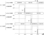
- 10 is a timing chart showing an example of when the operating state of each sensor device is switched.
- 10 is a timing chart showing an example of when the operating state of each sensor device is switched.
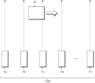
- FIG. 1 is a schematic diagram for explaining the concept of a sensor system according to an embodiment.
- 13 is a schematic diagram illustrating a state in which a cardboard box, which is an object, is detected by three sensor devices linked together as a sensor system in the modified example.
- FIG. 11 is a graph illustrating an example of a frequency distribution of an OFF time of a detection signal when a cardboard box is detected.
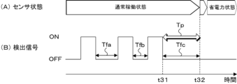
- 10 is a timing chart for switching a sensor device in a modified example from a normal operation state to a power saving state.
- a schematic configuration of a sensor device constituting a sensor system will be described.
- the sensor device 1 is a photoelectric sensor
- photoelectric sensors can be classified into, for example, a reflective type that detects an object based on the amount of light reflected by the object and a transmissive type that detects an object based on the light being blocked by the object.
- a reflective photoelectric sensor will be described.
- a mode will be described in which a plurality of sensor devices 1 are connected together and operated as a sensor system 100 including the connected plurality of sensor devices 1.
- a means for connecting the sensor devices 1 together for example, a connector that directly connects the sensor devices 1 together, a wired connection such as a cable, wireless communication, etc. can be appropriately used.
- FIG. 1 is a block diagram illustrating the general configuration of the sensor device 1.
- the sensor device 1 includes, for example, a light-projecting unit 10, a light-receiving unit 20, a control unit 30, a memory unit 40, a display unit 50, an input/output I/F (interface) 60, an operation unit 70, light-projecting circuits 81a, 81b, light-emitting elements 82a, 82b, light-receiving circuits 83a, 83b, and light-receiving elements 84a, 84b.
- the light-projecting unit 10, the light-receiving unit 20, the control unit 30, the memory unit 40, the display unit 50, the input/output I/F 60, the operation unit 70, the light-projecting circuits 81a, 81b, the light-emitting elements 82a, 82b, the light-receiving circuits 83a, 83b, and the light-receiving elements 84a, 84b are housed in a housing.
- the components of the sensor device 1 are not limited to being housed in a single housing, and each component of the sensor device 1 may be housed in two or more separate housings.
- the light-projecting unit 10 is configured to output (project) measurement light toward an object.
- the light-projecting unit 10 includes, for example, a light-emitting element such as an LED (Light Emitting Diode) and a drive circuit that drives the light-emitting element.
- a light-emitting element such as an LED (Light Emitting Diode)
- a drive circuit that drives the light-emitting element.
- the light receiving unit 20 is configured to receive light and obtain the amount of received light.
- the light receiving unit 20 includes, for example, a light receiving element such as a PD (photodiode), an amplifier circuit, and an A/D conversion circuit.
- the control unit 30 is configured to control the operation of each part of the sensor device 1.
- the control unit 30 includes a processor such as a CPU (Central Processing Unit). Specifically, the control unit 30 executes a detection process based on the received light amount data input from the light receiving unit 20 while controlling the operation of the light projecting unit 10 and the light receiving unit 20 in accordance with a program stored in a storage unit 40 including a memory. The result of the detection process is output via the display unit 50 or the input/output I/F 60.
- the control unit 30 will be described in detail later.
- the storage unit 40 is configured to store programs, data, and the like.
- the storage unit 40 is configured to include memories such as a ROM (Read Only Memory), a RAM (Random Access Memory), and a buffer memory.
- the storage unit 40 stores data such as programs executed by the control unit 30, setting items and setting contents, and set values.
- the display unit 50 is configured to display information.
- the display unit 50 includes, for example, a display such as an organic electroluminescence display (OLED) and an indicator light such as an LED (Light Emitting Diode).
- OLED organic electroluminescence display
- LED Light Emitting Diode
- the input/output I/F 60 is configured as an interface with external devices including other sensor devices 1 and controllers (control devices).
- the input/output I/F 60 has a function of exchanging data and signals with external devices, for example, and controlling communication with external devices.
- the operation unit 70 is configured to input information.
- the operation unit 70 includes, for example, buttons, switches, a touch panel, a keyboard, etc.
- the light-emitting circuits 81a and 81b, the light-emitting elements 82a and 82b, the light-receiving circuits 83a and 83b, and the light-receiving elements 84a and 84b are used for optical communication between adjacent sensor devices 1 on the left and right.
- the light-emitting elements 82a and 82b can be, for example, LEDs
- the light-receiving elements 84a and 84b can be, for example, PDs.
- control unit 30 controls the light-projecting circuits 81a, 81b on the left and right of the sensor device 1 to emit light from the left and right light-emitting elements 82a, 82b to the adjacent sensor device 1.
- the light that reaches the adjacent sensor device 1 is received by the left and right light-receiving elements 84a, 84b, and reaches the control unit 30 via the light-receiving circuits 83a, 83b, where it is used for processing.
- a different channel number is assigned to each of the multiple sensor devices 1 that are connected.
- a sensor device 1 optically communicates with adjacent sensor devices 1 on the left and right, it can transmit information including the channel number of its own device as well as the change in the detection signal and trigger signals, which will be described later. This allows the other sensor devices 1 that receive the information to recognize, for example, which sensor device 1 sent what signal and how the detection state is changing in that device.
- the control unit 30 includes functional elements such as a detection unit 31 and a switching unit 32.
- the detection unit 31 outputs a detection signal indicating "ON” or “OFF” as a detection result. Specifically, when the amount of received light is equal to or greater than the threshold, the detection unit 31 outputs an "ON” detection signal indicating that an object has been detected. On the other hand, when the amount of received light is less than the threshold, the detection unit 31 outputs an "OFF" detection signal indicating that an object has not been detected.
- the switching unit 32 switches the operating state of the sensor device 1 between a power-saving state and a normal operating state.
- the power-saving state is an operating state that is set to consume less power than the normal operating state by reducing the intensity (power) of the projected light.
- the switching unit 32 switches the intensity of the projected light from a high level, which is the normal operating state, to a low level, which is the power-saving state. This makes it possible to transition the operating state of the sensor device 1 in the normal operating state to a power-saving state.
- the switching unit 32 switches the intensity of the projected light from a low level, which is a power-saving state, to a high level, which is a normal operating state, when triggered by the operation of a higher-level sensor device 1 among the multiple sensor devices 1 connected as the sensor system 100. This allows the operating state of the sensor device 1 that has switched to the power-saving state to be restored to the normal operating state.
- the sensor device 1 that is connected upstream based on the direction in which the object to be detected is transported will be described as the higher-level sensor device 1. Therefore, the sensor device 1 that is connected most upstream in the direction in which the object is transported will be the top sensor device 1, and the sensor device 1 that is connected most downstream will be the lowest-level sensor device 1.
- the sensor device 1 located at either end of the connected sensor device group may be the highest-level sensor device 1. In this case, the sensor device 1 located at the other end becomes the lowest-level sensor device 1.
- the sensor device 1 with the smallest channel number may also be the highest-level sensor device 1. In this case, the sensor device 1 with the smallest channel number becomes the highest-level sensor device 1, and the sensor device 1 with the largest channel number becomes the lowest-level sensor device 1.
- Wireless communication may be used when communicating between connected sensor devices 1. In this case, when communicating wirelessly, it is preferable to transmit information including, for example, the channel number of the own device, the channel number of the destination, the change state of the detection signal described below, and the trigger signal.
- the sensor device 1 can switch the operating state of the other sensor devices 1 when a target object is detected by one of the multiple connected reference sensor devices 1.
- the operation of the higher-level sensor device 1 that serves as a trigger can include, for example, either (1) or (2) below.
- the measurement light output of the lower-level sensor device 1 may also be turned OFF (zero intensity). By turning it OFF, the light emitted by the lower-level sensor device 1 can be completely turned off, which can further improve the power saving effect.
- the power saving state is not limited to being realized only by reducing the intensity of the projected light.
- other requirements that can reduce power consumption can be set as appropriate, such as stopping part or all of the display on the display unit 50 that displays the detection results of the target object, or putting some of the functions of the sensor device 1 into sleep mode.
- control unit 30 can, for example, appropriately output to the outside the detection state by the detection unit 31 or the switching state by the switching unit 32.
- the outside may be an external device or an external display device.
- the control unit 30 outputs to the outside at least the detection state of the object in the normal operation state after switching.
- the state of the detection signal may be determined once when switching from a power saving state to a normal operating state and once during normal operating state after switching, and based on each determination result, information on how the operating state of the sensor device 1 has changed and the state of the detection signal may be output to the outside.
- FIG. 2 is a timing chart showing an example of when the operating state of each sensor device 1 is switched when the above (1) is adopted.
- FIG. 3 is a timing chart showing an example of when the operating state of each sensor device 1 is switched when the above (2) is adopted.
- Figs. 2 and 3 will be used to explain a case where the sensor system 100 connects three sensor devices 1.
- the first sensor device 1, the second sensor device 1, and the third sensor device 1 are connected in this order from the top of the connection.
- the first sensor device 1 is in a normal operating state, and the second and third sensor devices 1 are in a power saving state.
- the timing chart of FIG. 2 will be described.
- the detection signal from the detector 31 of the first sensor device 1 in FIGS. 2A and 2B becomes "ON", indicating that an object is being detected.
- the detection signal from the detection unit 31 of the first sensor device 1 in Figures 2(A)(b) becomes "OFF", indicating that no object is being detected.
- the first sensor device 1 in Figure 2(A) transmits a trigger signal Sa to the second sensor device 1, and switches the intensity of the light projected by the light projector 10 of the first sensor device 1 from high to low.
- the period from time t2 to time t3 is a transition period in which the intensity of the light projected is switched from high to low.
- the switching unit 32 of the second sensor device 1 in FIG. 2(B) that has received the trigger signal Sa switches the intensity of the light projected by the light-projecting unit 10 from low level to high level. This causes the operating state of the second sensor device 1 in FIG. 2(B)(a) to return to the normal operating state.
- the period from time t2 to time t3 is a transition period during which the intensity of the light projected is switched from low level to high level.
- the detection signal from the detection unit 31 of the second sensor device 1 in Figure 2(B)(b) becomes "OFF", indicating that no object is being detected.
- the second sensor device 1 in Figure 2(B) transmits a trigger signal Sb to the third sensor device 1, and switches the intensity of the light projected by the light projector 10 of the second sensor device 1 from high to low.
- the period from time t4 to time t5 is a transition period in which the intensity of the light projected is switched from high to low.
- the switching unit 32 of the third sensor device 1 in FIG. 2(C) that receives the trigger signal Sb switches the intensity of the light projected by the light-projecting unit 10 from low level to high level. This causes the operating state of the third sensor device 1 in FIG. 2(C)(a) to return to the normal operating state.
- the period from time t4 to time t5 is a transition period during which the intensity of the light projected is switched from low level to high level.
- the detection signal from the detection unit 31 of the third sensor device 1 in Figure 2(C)(b) becomes "OFF", indicating that no object is being detected.
- the third sensor device 1 in Figure 2(C) transmits a trigger signal Sc to the first sensor device 1, and switches the intensity of the light projected by the light projector 10 of the third sensor device 1 from high to low. This causes the operating state of the third sensor device 1 in Figure 2(C)(a) to transition to a power saving state.
- the period from time t6 to time t7 is a transition period in which the intensity of the light projected is switched from high to low.
- the switching unit 32 of the first sensor device 1 in FIG. 2(A) that has received the trigger signal Sc switches the intensity of the light projected by the light projecting unit 10 from low level to high level. This causes the operating state of the first sensor device 1 in FIG. 2(A)(a) to return to the normal operating state.
- the period from time t6 to time t7 is a transition period during which the intensity of the light projected is switched from low level to high level.
- the operating state of the first sensor device 1 in FIG. 2(A)(a) is switched between a normal operating state and a power saving state, but it may be maintained in the normal operating state without switching.
- the trigger signals Sa, Sb, and Sc are transmitted when the detection signal by the detection unit 31 of the sensor device 1 connected one level higher becomes “OFF", but the timing of transmitting the trigger signals Sa, Sb, and Sc is not limited to this.
- the trigger signals Sa, Sb, and Sc may be transmitted when the detection signal by the detection unit 31 of the sensor device 1 connected one level higher becomes "ON”.
- the trigger signals Sa, Sb, and Sc may be transmitted at any timing from when the detection signal by the detection unit 31 of the sensor device 1 connected one level higher changes from "ON" to "OFF".
- the detection signal by the detector 31 of the first sensor device 1 in Fig. 3(A) and (b) becomes "ON" indicating that an object is being detected.
- the first sensor device 1 in Fig. 3(A) transmits a trigger signal Sa to the second sensor device 1.
- the second sensor device 1 in FIG. 3(B) receives the trigger signal Sa and transmits a trigger signal Sb to the third sensor device 1, and switches the intensity of the light projected by the light-projecting unit 10 of the second sensor device 1 from low to high.
- the third sensor device 1 in FIG. 3(C) receives the trigger signal Sb and switches the intensity of the light projected by the light-projecting unit 10 of the third sensor device 1 from low level to high level.
- the operating state of the second sensor device 1 in FIG. 3(B)(a) and the operating state of the third sensor device 1 in FIG. 3(C)(a) are restored to their normal operating states, and all three connected sensor devices 1 are in their normal operating states.
- the period from time t11 to time t12 is a transition period in which the intensity of the projected light switches from low to high.
- the detection signal from the detection unit 31 of the second sensor device 1 in Figure 3(B)(b) becomes "OFF", indicating that no object is being detected.
- the second sensor device 1 in Figure 3(B) switches the intensity of the light projected by the light-projecting unit 10 from high to low. This causes the operating state of the second sensor device 1 in Figure 3(B)(a) to transition to a power-saving state.
- the period from time t13 to time t14 is a transition period in which the intensity of the light projected is switched from high to low.
- the detection signal from the detection unit 31 of the third sensor device 1 in Figure 3(C)(b) becomes "OFF", indicating that no object is being detected.
- the third sensor device 1 in Figure 3(C) switches the intensity of the light projected by the light-projecting unit 10 from high to low. This causes the operating state of the third sensor device 1 in Figure 3(C)(a) to transition to a power-saving state.
- the period from time t15 to time t16 is a transition period in which the intensity of the light projected is switched from high to low.
- the first sensor device 1 transmits a trigger signal Sa to the second sensor device 1, and the second sensor device 1 transmits a trigger signal Sb to the third sensor device 1, but the first sensor device 1 may transmit a trigger signal Sa to each of the second sensor device 1 and the third sensor device 1.
- the operating state of the first sensor device 1 in FIG. 3(A)(a) is maintained as the normal operating state, but the normal operating state and the power saving state may be switched based on the detection signal from the detection unit 31 of the first sensor device 1 in FIG. 3(A)(b). For example, when the detection signal from the detection unit 31 of the first sensor device 1 becomes "OFF", the intensity of the light projected by the light-projecting unit 10 is switched from high level to low level, and the operating state is transitioned to the power saving state. On the other hand, when the detection signal from the detection unit 31 of the first sensor device 1 becomes "ON", the intensity of the light projected by the light-projecting unit 10 is switched from low level to high level, and the operating state is restored to the normal operating state.
- FIG. 4 is a schematic diagram for explaining the concept of a sensor system 100 according to an embodiment.
- FIG. 4 illustrates a sensor system 100 in which n sensor devices 1a to 1n are connected together.
- an object O such as a workpiece
- the sensors are connected in the order of sensor device 1a, sensor device 1b, sensor device 1c, sensor device 1d, ..., sensor device 1n.
- the lower sensor device 1 is triggered by the operation of the higher sensor device 1 to switch the intensity of the light it projects from a low level, which is a power-saving state, to a high level, which is a normal operating state. Then, when the sensor device 1 that has returned to the normal operating state detects an object O and the object O is no longer detected, the intensity of the light it projects is switched from the high level, which is a normal operating state, to the low level, which is a power-saving state.
- the light projection intensity is switched from high to low, causing the device to transition from a normal operating state to a power-saving state, and when an object is detected in a connected higher-level sensor device 1, the light projection intensity in the lower-level sensor device 1 is switched from low to high, causing the device to return from the power-saving state to the normal operating state.
- the sensor system 100 can effectively reduce power consumption and reliably detect objects while eliminating the need for operations when switching to a power-saving state or returning to a normal operating state.
- external devices such as image lighting that operate in response to a trigger from the sensor system 100 can also be switched to a power-saving state or stopped state at the same timing as necessary, which can contribute to power savings on the external device side as well.
- the upper sensor device 1 switches the intensity of the light projected and the detection signal using the amount of light received by the light receiving unit 20, but the elements used to switch the intensity of the light projected and the detection signal are not limited to the amount of light received.
- the operating state and the detection signal may be switched using light reception position information, measurement calculation values, wavelength intensity, etc.
- the sensor device 1 is a displacement sensor, the intensity of the light projected can be switched using the amount of light received, and the detection signal can be switched using the light reception position.
- the switching unit 32 in the embodiment described above switches the intensity of the light projected by the light-projecting unit 10 from a high level (normal operating state) to a low level (power-saving state) when the detection signal from the detection unit 31 becomes "OFF," but the timing of switching from a high level to a low level is not limited to this.
- the switching unit 32 may switch the intensity of the light projected by the light-projecting unit 10 from a high level to a low level when the next object is not detected even after the period (time) for detecting the object has elapsed.
- FIG. 5 is a schematic diagram illustrating a state in which the target objects in this modified example, cardboard boxes Ca, Cb, and Cc (hereinafter also referred to as "cardboard box C"), are detected by three sensor devices 1a, 1b, and 1c connected as sensor system 100.
- Each cardboard box C is transported by a belt conveyor from the left side to the right side of the paper.
- the intervals at which each cardboard box C is transported vary slightly depending on the timing at which each cardboard box C is placed on the belt conveyor. Therefore, the time intervals at which each sensor device 1a, 1b, and 1c detects each cardboard box Ca, Cb, and Cc will also vary slightly.
- Figure 6 is a graph illustrating the frequency distribution of the OFF time from when the detection signal from the detection unit 31 turns “OFF” to when it turns “ON” when detecting a group of cardboard boxes being transported on a conveyor belt. As illustrated in Figure 6, the OFF time between each cardboard box peaks at time t21, with some variation before and after.
- the next cardboard box or the like may not arrive for some time.
- the switching unit 32 switches the intensity of the light projected by the light-projecting unit 10 from a high level to a low level when a predetermined time has elapsed between the time it is determined that a cardboard box has not been detected and the time the next cardboard box is detected (hereinafter also referred to as the "OFF time")
- the above-mentioned predetermined time takes into consideration the OFF time between each cardboard box when detecting cardboard boxes transported by the conveyor belt, and is preferably set to a time slightly longer than the upper limit of the range in which each OFF time is distributed.
- the predetermined time is set to time t22, which is slightly longer than the upper limit of the distribution range that peaks at time t21. Therefore, when the OFF time has elapsed beyond time t22, the switching unit 32 switches the intensity of the light projected by the light-projecting unit 10 from a high level to a low level. On the other hand, when the OFF time is less than time t22, the switching unit 32 maintains the intensity of the light projected by the light-projecting unit 10 at a high level.
- FIG. 7 is a timing chart showing how the sensor device 1 in this modified example switches from a normal operating state to a power saving state.
- the OFF time Tfc that started at time t31 reaches the predetermined time Tp.
- the intensity of the light projected by the light-projecting unit 10 switches from a high level to a low level, and the normal operating state switches to a transition state and then to a power-saving state.
- the sensor system 100 when detecting a cardboard box being transported by a conveyor belt, if the cardboard box is not being transported for a longer period than normal, it is possible to reduce the power consumption until the next cardboard box is transported.
- the sensor device 1 of the above-described embodiment may further be provided with an operation mode.
- the operation modes may be a constant normal operation mode and a time-saving power-saving operation mode.
- the constant normal operation mode is an operation mode in which the normal operation state is always maintained
- the time-saving power-saving operation mode is an operation mode in which the normal operation state and the power-saving operation state are switched based on an external trigger.
- the user can set the desired operation mode, for example, by operating the operation unit 70.
- a sensor device 1 that issues a trigger to other sensor devices 1 is set to a normal operation mode at all times, and a sensor device 1 that receives a trigger and returns to a normal operation state is set to a power-saving operation mode as appropriate.
- a sensor device 1 that receives a trigger and returns to a normal operation state is set to a power-saving operation mode as appropriate.
- the intensity of the projected light is switched from a low level, which is a power saving state, to a high level, which is a normal operating state, by using the operation of a higher-level sensor device 1 as a trigger among multiple sensor devices 1 connected as the sensor system 100, but this is not limited to this.
- each of the control units (30) uses detection of the object in the sensor device (1) that is connected to a higher level among the multiple connections as a trigger. 2.
- each of the control units (30) uses detection of the object in the sensor device (1) connected upstream based on the direction in which the object to be detected is transported as a trigger. 2.
- each of the control units (30) switches an output state of the measurement light from the power saving state to the normal operation state while the object is being detected by any of the plurality of connected sensor devices (1); 4.
- Each of the control units (30) switches an output state of the measurement light from the normal operation state to the power saving state when the object is not detected. 6.
- each of the control units (30) switches an output state of the measurement light from the normal operation state to the power saving state when a next object is not detected even after a predetermined time has elapsed since it was determined that the object was not detected. 7.
- an output level of the measurement light in the power saving state is a value lower than an output level of the measurement light in the normal operation state; 8.
- each of the control units (30) When switching from the normal operation state to the power saving state, each of the control units (30) further stops a part or all of the display on a display unit that displays the detection result of the object, and puts some of the functions of the sensor device (1) into sleep mode.
- a sensor device (1) that can be incorporated into a sensor system (100) that connects a plurality of sensor devices (1) that detect an object using reflected light or transmitted light obtained by outputting measurement light toward the object, A control unit (30) that switches an output state of the measurement light between a normal operation state and a power saving state, the control unit (30) switches the output state of the measurement light from the power saving state to the normal operation state when a detection of the object by any one of the multiple connected sensor devices (1) is used as a trigger.
- Sensor device (1) Sensor device (1).
- control unit (30) uses detection of the object in the sensor device (1) that is connected to a higher level among the multiple connections as a trigger. 12.
- the sensor device (1) according to claim 11.
- control unit (30) uses detection of the object in the sensor device (1) connected upstream with respect to the direction in which the object to be detected is transported as a trigger. 12.
- the sensor device (1) according to claim 11.
Landscapes
- Geophysics And Detection Of Objects (AREA)
- Switches Operated By Changes In Physical Conditions (AREA)
- Electronic Switches (AREA)
Abstract
省電力状態への移行や通常稼働状態に復帰する際の操作を省くことができるセンサシステム及びセンサ装置を提供する。センサシステム100は、計測光を対象物に向けて出力して得られる反射光又は透過光を用いて対象物を検出するセンサ装置1を複数連結するセンサシステム100であって、センサ装置1の各々は、計測光の出力状態を通常稼働状態と省電力状態とに切り替える制御部30をそれぞれ備え、制御部30の各々は、複数連結されているいずれかのセンサ装置1における対象物の検出をトリガにして、計測光の出力状態を省電力状態から通常稼働状態にそれぞれ切り替える。
Description
本発明は、センサシステム及びセンサ装置に関する。
下記特許文献1には、省電力表示モードを有するセンサ装置が開示されている。このセンサ装置は、通常表示モードの他に、表示器を全消灯状態にする第1の省電力表示モードと、センサが動作中か否か、又は正常に動作しているか否かの基本的な情報のみを視認性良く表示しながら、消費電力を大幅に低減することができる第2の省電力表示モードとを備えている。
特許文献1のセンサ装置では、上記三つの表示モードを、押し釦スイッチを押下することで、順番に切り替えることができるようになっている。したがって、省電力表示モードに移行させる際や通常表示モードに復帰させるたびに、押し釦スイッチを押下する必要があり、モードを切り替えるのに手間がかかる。
このような事情に鑑み、本発明は、省電力状態への移行や通常稼働状態に復帰する際の操作を省くことができるセンサシステム及びセンサ装置を提供することを目的とする。
本発明の一態様に係るセンサシステムは、計測光を対象物に向けて出力して得られる反射光又は透過光を用いて対象物を検出するセンサ装置を複数連結するセンサシステムであって、センサ装置の各々は、計測光の出力状態を通常稼働状態と省電力状態とに切り替える制御部をそれぞれ備え、制御部の各々は、複数連結されているいずれかのセンサ装置における対象物の検出をトリガにして、計測光の出力状態を省電力状態から通常稼働状態にそれぞれ切り替える。
この態様によれば、複数連結されているセンサ装置のうち、いずれかのセンサ装置で対象物が検出されたことをトリガにして、他のセンサ装置における計測光の出力状態を省電力状態から通常稼働状態に切り替えることができる。これにより、消費電力を抑えつつ、対象物を確実に検出することが可能となる。
上述した態様において、制御部の各々は、計測光の出力状態を省電力状態から通常稼働状態にそれぞれ切り替える際に、複数連結のうち上位に連結されているセンサ装置における前記対象物の検出をトリガにしてもよいし、検出しようとする対象物が搬送される方向を基準にして上流側に連結されているセンサ装置における対象物の検出をトリガにしてもよい。
上述した態様において、制御部の各々は、複数連結されているいずれかのセンサ装置で対象物が検出されている間に、計測光の出力状態を省電力状態から通常稼働状態にそれぞれ切り替えてもよい。
この態様によれば、複数連結されているいずれかのセンサ装置で対象物が検出されていることをトリガにして、その他のセンサ装置における計測光の出力状態を省電力状態から通常稼働状態に切り替えることができる。
上述した態様において、複数連結されているいずれかのセンサ装置における対象物の検出をトリガにして、その他の各センサ装置の制御部は、計測光の出力状態を省電力状態から通常稼働状態にそれぞれ切り替えてもよい。
この態様によれば、複数連結されているいずれかのセンサ装置で対象物が検出されたことをトリガにして、その他の各センサ装置における計測光の出力状態を省電力状態から通常稼働状態にそれぞれ切り替えることができる。
上述した態様において、制御部の各々は、対象物が検出されないときに、計測光の出力状態を通常稼働状態から省電力状態にそれぞれ切り替えてもよい。
この態様によれば、各センサ装置において、対象物が検出されないことをトリガにして、計測光の出力状態を通常稼働状態から省電力状態に自動的に切り替えることができるため、消費電力を有効に抑えることが可能となる。
上述した態様において、制御部の各々は、対象物が検出されていないと判定してから所定時間が経過しても次の対象物が検出されないときに、計測光の出力状態を通常稼働状態から省電力状態にそれぞれ切り替えてもよい。
この態様によれば、対象物がしばらく搬送されてこない場合に、次の対象物が搬送されてくるまでの消費電力を削減することが可能となる。
上述した態様において、省電力状態における計測光の出力レベルは、通常稼働状態における計測光の出力レベルよりも低い値であってもよく、さらに、対象物を検出することができる範囲内での下限値付近であるか、OFFであってもよい。
この態様によれば、省電力状態に切り替えても、対象物を検出しつつ、消費電力を確実に抑えることが可能となる。
上述した態様において、制御部の各々は、通常稼働状態から省電力状態に切り替える際に、さらに、対象物の検出結果を表示する表示部への表示の一部又は全部を停止させ、センサ装置の機能の一部をスリープさせてもよい。
この態様によれば、省電力状態に切り替えることで、表示部やセンサ装置の機能の少なくとも一部を停止させることができるため、消費電力をさらに抑えることが可能となる。
本発明の他の態様に係るセンサ装置は、計測光を対象物に向けて出力して得られる反射光又は透過光を用いて対象物を検出するセンサ装置を複数連結するセンサシステムに組み込み可能なセンサ装置であって、計測光の出力状態を通常稼働状態と省電力状態とに切り替える制御部を備え、制御部は、複数連結されているいずれかのセンサ装置での対象物の検出をトリガにして、計測光の出力状態を省電力状態から通常稼働状態に切り替える。
この態様によれば、複数のセンサ装置を連結するセンサシステムに組み込まれたときに上位に連結されるセンサ装置において対象物が検出されたことをトリガにして、計測光の出力状態を省電力状態から通常稼働状態に切り替えることができる。これにより、消費電力を抑えつつ、対象物を確実に検出することが可能となる。
本発明によれば、省電力状態への移行や通常稼働状態に復帰する際の操作を省くことができるセンサシステム及びセンサ装置を提供することができる。
添付図面を参照して、本発明の好適な実施形態について説明する。なお、各図において、同一の符号を付したものは、同一又は同様の構成を有する。ただし、図面は模式的なものであり、具体的な寸法等は以下の説明を照らし合わせて判断するべきものである。また、図面相互間においても互いの寸法の関係や比率が異なる部分が含まれていることは勿論である。
図1を参照して、実施形態に係るセンサシステムを構成するセンサ装置の概略構成について説明する。本実施形態では、例示的に、センサ装置1が光電センサである場合について説明する。ここで、光電センサは、例えば、対象物によって反射された光の受光量に基づいて対象物を検出する反射型と、対象物によって光が遮られることに基づいて対象物を検出する透過型とに分類することができる。以下の説明では、センサ装置1が反射型の光電センサである場合について説明する。
また、本実施形態では、複数のセンサ装置1を連結させ、その連結させた複数のセンサ装置1を含むセンサシステム100として運用する態様について説明する。センサ装置1同士を連結させる手段として、例えば、センサ装置1同士を直接連結するコネクタや、ケーブル等の有線、無線通信等を適宜用いることができる。
図1は、センサ装置1の概略構成を例示するブロック図である。
図1に示すように、センサ装置1は、例えば、投光部10と、受光部20と、制御部30と、記憶部40と、表示部50と、入出力I/F(インターフェース)60と、操作部70と、投光回路81a、81bと、発光素子82a、82bと、受光回路83a、83bと、受光素子84a、84bと、を備える。投光部10、受光部20、制御部30、記憶部40、表示部50、入出力I/F60、操作部70、投光回路81a、81b、発光素子82a、82b、受光回路83a、83b、及び受光素子84a、84bは、筐体に収容される。
センサ装置1の各部は、1つの筐体に収容される構成に限定されず、センサ装置1の各部が2つ以上に分けて収容されてもよい。
投光部10は、対象物に向けて計測光を出力(投光)するように構成されている。投光部10は、例えば、LED(Light Emitting Diode)等の発光素子と、発光素子を駆動する駆動回路と、を含む。
受光部20は、光を受けて受光量を得るように構成されている。受光部20は、例えば、PD(フォトダイオード)等の受光素子と、増幅回路と、A/D変換回路と、を含む。
制御部30は、センサ装置1の各部の動作を制御するように構成されている。制御部30は、例えば、CPU(Central Processing Unit)等のプロセッサを含んで構成される。具体的に、制御部30は、メモリを含んで構成される記憶部40に記憶されたプログラムに従って、投光部10及び受光部20の動作を制御しながら、受光部20から入力される受光量データに基づいて検出処理を実行する。検出処理の結果は、表示部50又は入出力I/F60を介して出力される。なお、制御部30の詳細については、後述する。
記憶部40は、プログラムやデータ等を記憶するように構成されている。記憶部40は、例えば、ROM(Read Only Memory)、RAM(Random Access Memory)、バッファメモリ等のメモリを含んで構成される。具体的に、記憶部40は、制御部30が実行するプログラム、設定項目及び設定内容、並びに設定された値等のデータを記憶する。
表示部50は、情報を表示するように構成されている。表示部50は、例えば、有機ELディスプレイ(OLED:Organic Electro-Luminescence Display)等のディスプレイと、LED(Light Emitting Diode)等の表示灯とを含んで構成される。
入出力I/F60は、他のセンサ装置1やコントローラ(制御装置)等を含む外部機器とのインターフェースとして構成されている。入出力I/F60は、例えば、外部機器との間でデータや信号をやり取りし、外部機器との通信を制御する機能を有する。
操作部70は、情報を入力するように構成されている。操作部70は、例えば、ボタン、スイッチ、タッチパネル、キーボード等を含んで構成される。
投光回路81a、81b、発光素子82a、82b、受光回路83a、83b、及び受光素子84a、84bは、左右に隣接するセンサ装置1との間で光通信するために利用される。発光素子82a、82bとして、例えば、LEDを用いることができ、受光素子84a、84bとして、例えば、PDを用いることができる。
具体的に、センサ装置1の左右にある投光回路81a、81bを制御部30が制御して、左右の発光素子82a、82bから隣接するセンサ装置1に対して光を放出する。隣接するセンサ装置1に到来する光は、左右の受光素子84a、84bで受光され、受光回路83a、83bを介して制御部30に到来し、制御部30での処理に利用される。
ここで、連結される複数のセンサ装置1には、それぞれ異なるチャネル番号が割り当てられている。センサ装置1は、左右に隣接するセンサ装置1と光通信する際に、自装置のチャネル番号の他に、後述する検出信号の変化状態やトリガ信号など含む情報を送信することができる。これにより、情報を受信した他のセンサ装置1は、例えば、どのセンサ装置1から、どのような信号が送信され、その装置で検出状態がどのように変化しているのかを認識することができる。
制御部30は、機能的な要素として、例えば、検出部31と、切替部32と、を含む。
検出部31は、受光部20が得る受光量と閾値とに基づいて、例えばワーク等の対象物を検出する。閾値は、対象物を検出していると判定できるときの受光量の範囲内に設定することが好ましい。
検出部31は、検出結果として、「ON」又は「OFF」を表す検出信号を出力する。具体的に、検出部31は、受光量が閾値以上であるときに、対象物を検出していることを示す「ON」の検出信号を出力する。他方、検出部31は、受光量が閾値未満であるときに、対象物を検出していないことを示す「OFF」の検出信号を出力する。
切替部32は、センサ装置1の稼働状態を省電力状態と通常稼働状態とに切り替える。省電力状態は、投光の強度(パワー)を弱めることにより、通常稼働状態よりも消費電力が低くなるように設定された稼働状態である。
具体的に、切替部32は、検出部31による検出信号が対象物を検出していることを示す「ON」から対象物を検出していないことを示す「OFF」になったときに、投光の強度を、通常稼働状態であるハイレベルから省電力状態であるローレベルに切り替える。これにより、通常稼働状態のセンサ装置1における稼働状態を省電力状態に移行させることができる。
他方、切替部32は、センサシステム100として連結された複数のセンサ装置1のうち、上位にあるセンサ装置1の動作をトリガにして、投光の強度を、省電力状態であるローレベルから通常稼働状態であるハイレベルに切り替える。これにより、省電力状態に移行していたセンサ装置1の稼働状態を通常稼働状態に復帰させることができる。
ここで、本実施形態では、例示的に、連結される複数のセンサ装置1のうち、検出しようとする対象物が搬送される方向を基準にして上流側に連結されているセンサ装置1を上位のセンサ装置1として説明する。したがって、対象物が搬送される方向において最も上流側に連結されているセンサ装置1が最上位のセンサ装置1となり、最も下流側に連結されているセンサ装置1が最下位のセンサ装置1となる。
なお、連結しているセンサ装置群のいずれか一方の端に位置するセンサ装置1を最上位のセンサ装置1としてもよい。この場合、他方の端に位置するセンサ装置1が最下位のセンサ装置1となる。また、チャネル番号が小さいセンサ装置1を上位のセンサ装置1としてもよい。この場合、チャネル番号が最も小さいセンサ装置1が最上位のセンサ装置1となり、チャネル番号が最も大きいセンサ装置1が最下位のセンサ装置1となる。連結されているセンサ装置1間で通信する際に、無線通信を利用してもよい。この場合、無線通信する際に、例えば、自装置のチャネル番号、宛先となるチャネル番号、後述する検出信号の変化状態やトリガ信号など含む情報を送信することが好ましい。
このように、本実施形態に係るセンサ装置1は、複数連結されているいずれかの基準となるセンサ装置1における対象物の検出をトリガにして、他のセンサ装置1の稼働状態を切り替えることができる。
トリガとなる上位のセンサ装置1の動作には、例えば、以下の(1)又は(2)のいずれかを含むことができる。
(1)一つ上位に連結されているセンサ装置1の検出部31が、検出信号を「ON」から「OFF」にする動作
(2)最上位に連結されているセンサ装置1の検出部31が、検出信号を「OFF」から「ON」にする動作
なお、(1)及び(2)の詳細については、後述する。
(2)最上位に連結されているセンサ装置1の検出部31が、検出信号を「OFF」から「ON」にする動作
なお、(1)及び(2)の詳細については、後述する。
ここで、ローレベルの強度は、対象物を検出できる範囲内での下限値付近に設定することが好ましいが、下位のセンサ装置1の計測光の出力をOFF(強度ゼロ)にしてもよい。OFFにすることで、下位のセンサ装置1の投光を完全に消灯できるため、省電力の効果をさらに向上させることが可能となる。他方、ハイレベルの強度は、例えばフルパワーのように、S/N比を最大限に確保して対象物を確実に検出できる範囲内に設定することが好ましい。
また、省電力状態は、投光の強度を弱めることのみによって実現することには限定されない。投光の強度を弱めることに加え、例えば、対象物の検出結果を表示する表示部50への表示の一部又は全部を停止することや、センサ装置1の機能の一部をスリープさせること等のように、消費電力を抑制可能な他の要件を適宜設定することができる。
ここで、制御部30は、例えば、検出部31による検出状態や、切替部32による切替状態を、外部に適宜出力することができる。外部は、外部機器であってもよいし、外部の表示装置であってもよい。例示的に、制御部30は、省電力状態から通常稼働状態に切り替えられた後に、少なくとも、切替後の通常稼働状態における対象物の検出状態を外部に出力することが好ましい。
例えば、省電力状態から通常稼働状態に切り替える時と、切替後の通常稼働状態時とでそれぞれ1回ずつ検出信号の状態を判定し、それぞれの判定結果に基づいて、センサ装置1の稼働状態がどのように遷移し、検出信号がどのような状態になっているのかを、外部に出力してもよい。
図2及び図3を参照して、複数のセンサ装置1を含むセンサシステム100の動作の一例について説明する。
図2は、上記(1)を採用したときに、各センサ装置1の稼働状態が切り替わる際の一例を示すタイミングチャートである。図3は、上記(2)を採用したときに、各センサ装置1の稼働状態が切り替わる際の一例を示すタイミングチャートである。
図2及び図3では、説明の便宜のために、センサシステム100が3台のセンサ装置1を連結している場合について説明する。このセンサシステム100では、連結の上位側から、1台目のセンサ装置1、2台目のセンサ装置1、3台目のセンサ装置1の順に連結されている。タイミングチャートのスタート時は、1台目のセンサ装置1が通常稼働状態であり、2台目及び3台目のセンサ装置1が省電力状態になっている。
まず、図2のタイミングチャートについて説明する。
図2の時間t1において、図2(A)(b)の1台目のセンサ装置1の検出部31による検出信号が、対象物を検出していることを示す「ON」になる。
図2の時間t1において、図2(A)(b)の1台目のセンサ装置1の検出部31による検出信号が、対象物を検出していることを示す「ON」になる。
続いて、図2の時間t2において、図2(A)(b)の1台目のセンサ装置1の検出部31による検出信号が、対象物を検出していないことを示す「OFF」になる。このとき、図2(A)の1台目のセンサ装置1は、2台目のセンサ装置1にトリガ信号Saを送信するとともに、1台目のセンサ装置1の投光部10による投光の強度をハイレベルからローレベルに切り替える。これにより、図2(A)(a)の1台目のセンサ装置1の稼働状態が省電力状態に移行する。なお、時間t2から時間t3までは、投光の強度がハイレベルからローレベルに切り替わる移行期間となる。
続いて、トリガ信号Saを受信した図2(B)の2台目のセンサ装置1の切替部32は、投光部10による投光の強度をローレベルからハイレベルに切り替える。これにより、図2(B)(a)の2台目のセンサ装置1の稼働状態が通常稼働状態に復帰する。なお、時間t2から時間t3までは、投光の強度がローレベルからハイレベルに切り替わる移行期間となる。
続いて、図2の時間t4において、図2(B)(b)の2台目のセンサ装置1の検出部31による検出信号が、対象物を検出していないことを示す「OFF」になる。このとき、図2(B)の2台目のセンサ装置1は、3台目のセンサ装置1にトリガ信号Sbを送信するとともに、2台目のセンサ装置1の投光部10による投光の強度をハイレベルからローレベルに切り替える。これにより、図2(B)(a)の2台目のセンサ装置1の稼働状態が省電力状態に移行する。なお、時間t4から時間t5までは、投光の強度がハイレベルからローレベルに切り替わる移行期間となる。
続いて、トリガ信号Sbを受信した図2(C)の3台目のセンサ装置1の切替部32は、投光部10による投光の強度をローレベルからハイレベルに切り替える。これにより、図2(C)(a)の3台目のセンサ装置1の稼働状態が通常稼働状態に復帰する。なお、時間t4から時間t5までは、投光の強度がローレベルからハイレベルに切り替わる移行期間となる。
続いて、図2の時間t6において、図2(C)(b)の3台目のセンサ装置1の検出部31による検出信号が、対象物を検出していないことを示す「OFF」になる。このとき、図2(C)の3台目のセンサ装置1は、1台目のセンサ装置1にトリガ信号Scを送信するとともに、3台目のセンサ装置1の投光部10による投光の強度をハイレベルからローレベルに切り替える。これにより、図2(C)(a)の3台目のセンサ装置1の稼働状態が省電力状態に移行する。なお、時間t6から時間t7までは、投光の強度がハイレベルからローレベルに切り替わる移行期間となる。
続いて、トリガ信号Scを受信した図2(A)の1台目のセンサ装置1の切替部32は、投光部10による投光の強度をローレベルからハイレベルに切り替える。これにより、図2(A)(a)の1台目のセンサ装置1の稼働状態が通常稼働状態に復帰する。なお、時間t6から時間t7までは、投光の強度がローレベルからハイレベルに切り替わる移行期間となる。
これ以降は、上述した図2のタイミングチャートの各手順を先頭から繰り返し実行することになる。
ここで、図2では、図2(A)(a)の1台目のセンサ装置1の稼働状態を、通常稼働状態と省電力状態とに切り替えているが、切り替えずに通常稼働状態のまま維持してもよい。
また、図2では、一つ上位に連結されているセンサ装置1の検出部31による検出信号が「OFF」になったときに、トリガ信号Sa、Sb、Scを送信しているが、トリガ信号Sa、Sb、Scを送信するタイミングは、これに限定されない。例えば、一つ上位に連結されているセンサ装置1の検出部31による検出信号が「ON」になったときに、トリガ信号Sa、Sb、Scを送信してもよい。また、一つ上位に連結されているセンサ装置1の検出部31による検出信号が「ON」から「OFF」になるまでのいずれかのタイミングに、トリガ信号Sa、Sb、Scを送信してもよい。
次に、図3のタイミングチャートについて説明する。
図3の時間t11において、図3(A)(b)の1台目のセンサ装置1の検出部31による検出信号が、対象物を検出していることを示す「ON」になる。このとき、図3(A)の1台目のセンサ装置1は、2台目のセンサ装置1にトリガ信号Saを送信する。
図3の時間t11において、図3(A)(b)の1台目のセンサ装置1の検出部31による検出信号が、対象物を検出していることを示す「ON」になる。このとき、図3(A)の1台目のセンサ装置1は、2台目のセンサ装置1にトリガ信号Saを送信する。
そして、上記トリガ信号Saを受信した図3(B)の2台目のセンサ装置1は、3台目のセンサ装置1にトリガ信号Sbを送信するとともに、2台目のセンサ装置1の投光部10による投光の強度をローレベルからハイレベルに切り替える。
さらに、上記トリガ信号Sbを受信した図3(C)の3台目のセンサ装置1は、3台目のセンサ装置1の投光部10による投光の強度をローレベルからハイレベルに切り替える。
これらにより、図3(B)(a)の2台目のセンサ装置1の稼働状態及び図3(C)(a)の3台目のセンサ装置1の稼働状態が、それぞれ通常稼働状態に復帰し、連結している3台のセンサ装置1の全てが、通常稼働状態となる。なお、時間t11から時間t12までは、投光の強度がローレベルからハイレベルに切り替わる移行期間となる
続いて、図3の時間t13において、図3(B)(b)の2台目のセンサ装置1の検出部31による検出信号が、対象物を検出していないことを示す「OFF」になる。このとき、図3(B)の2台目のセンサ装置1は、投光部10による投光の強度をハイレベルからローレベルに切り替える。これにより、図3(B)(a)の2台目のセンサ装置1の稼働状態が省電力状態に移行する。なお、時間t13から時間t14までは、投光の強度がハイレベルからローレベルに切り替わる移行期間となる。
続いて、図3の時間t15において、図3(C)(b)の3台目のセンサ装置1の検出部31による検出信号が、対象物を検出していないことを示す「OFF」になる。このとき、図3(C)の3台目のセンサ装置1は、投光部10による投光の強度をハイレベルからローレベルに切り替える。これにより、図3(C)(a)の3台目のセンサ装置1の稼働状態が省電力状態に移行する。なお、時間t15から時間t16までは、投光の強度がハイレベルからローレベルに切り替わる移行期間となる。
これ以降は、上述した図3のタイミングチャートの各手順を先頭から繰り返し実行することになる。
ここで、図3では、1台目のセンサ装置1が2台目のセンサ装置1にトリガ信号Saを送信し、2台目のセンサ装置1が3台目のセンサ装置1にトリガ信号Sbを送信しているが、1台目のセンサ装置1が、2台目のセンサ装置1及び3台目のセンサ装置1のそれぞれにトリガ信号Saを送信してもよい。
また、図3では、図3(A)(a)の1台目のセンサ装置1の稼働状態を、通常稼働状態のまま維持しているが、図3(A)(b)の1台目のセンサ装置1の検出部31による検出信号に基づいて、通常稼働状態と省電力状態とを切り替えてもよい。例えば、1台目のセンサ装置1の検出部31による検出信号が「OFF」になったときに、投光部10による投光の強度をハイレベルからローレベルに切り替え、稼働状態を省電力状態に移行させる。他方、1台目のセンサ装置1の検出部31による検出信号が「ON」になったときに、投光部10による投光の強度をローレベルからハイレベルに切り替え、稼働状態を通常稼働状態に復帰させる。
図4は、実施形態に係るセンサシステム100の概念を説明するための模式図である。図4は、n台のセンサ装置1a~1nを連結させたセンサシステム100を例示する。同図では、例えばワーク等の対象物Oが、ベルトコンベアにより紙面の左側から右側に向けて搬送されている。このセンサシステム100では、連結の上位側(紙面の左側)から、センサ装置1a、センサ装置1b、センサ装置1c、センサ装置1d、…、センサ装置1nの順に連結されている。
図2及び図3のタイミングチャートを用いて説明したように、n台のセンサ装置1a~1nのうち、下位のセンサ装置1は、上位のセンサ装置1の動作をトリガにして、投光の強度を、省電力状態であるローレベルから通常稼働状態であるハイレベルにそれぞれ切り替える。そして、通常稼働状態に復帰したセンサ装置1が対象物Oを検出し、その対象物Oが検出されなくなると、投光の強度を、通常稼働状態であるハイレベルから省電力状態であるローレベルに切り替える。
このように、実施形態に係るセンサシステム100によれば、連結されている各センサ装置1において、対象物が検出されなくなったことをトリガにして、投光強度をハイレベルからローレベルに切り替えて通常稼働状態から省電力状態に移行させ、連結されている上位のセンサ装置1で対象物が検出されたことをトリガにして、下位のセンサ装置1における投光強度をローレベルからハイレベルに切り替えて省電力状態から通常稼働状態に復帰させることができる。
これにより、実施形態に係るセンサシステム100によれば、省電力状態への移行や通常稼働状態に復帰する際の操作を省きつつ、消費電力を有効に抑え、対象物を確実に検出することが可能となる。
また、省電力状態への移行や通常稼働状態に復帰する際の操作を省くことにより、移行や復帰のためのボタンや外部入力、通信手段などを省略することができるため、UIを簡易化することが可能となる。
さらに、省電力状態への移行や通常稼働状態に復帰する際の操作を省くことにより、センサ装置1の後段側のI/O回路などを削減することができるため、後段システムの負荷や立ち上げ時の設計工数を軽減することが可能となる。
加えて、センサシステム100からトリガを受けて稼働する、例えば、画像照明などの外部機器も、必要に応じて同様のタイミングで省電力状態や停止状態に切り替えることができるため、外部機器側の省電力化にも寄与することが可能となる。
[変形例]
上述した実施形態は、あらゆる点において本発明の例示に過ぎない。したがって、本発明の範囲を逸脱することなく種々の改良や変形を行うことができる。
上述した実施形態は、あらゆる点において本発明の例示に過ぎない。したがって、本発明の範囲を逸脱することなく種々の改良や変形を行うことができる。
例えば、上述した実施形態では、上位のセンサ装置1が、受光部20による受光量を用いて、投光の強度や検出信号を切り替えているが、投光の強度や検出信号の切り替えに用いる要素は、受光量に限定されない。受光量の他、受光位置情報や、計測演算値、波長強度などを用いて、稼働状態や検出信号を切り替えてもよい。具体的に、センサ装置1が変位センサである場合に、投光の強度は受光量を用いて切り替え、検出信号は受光位置を用いて切り替えることができる。
また、上述した実施形態に係る切替部32は、検出部31による検出信号が「OFF」になったときに、投光部10による投光の強度をハイレベル(通常稼働状態)からローレベル(省電力状態)に切り替えているが、ハイレベルからローレベルに切り替えるタイミングはこれに限定されない。
具体的に、切替部32は、対象物を検出する周期(時間)を超えても次の対象物が検出されないときに、投光部10による投光の強度をハイレベルからローレベルに切り替えてもよい。
本変形例について、図5乃至図7を参照して説明する。図5は、本変形例における対象物である段ボールCa、Cb、Cc(以下において、「段ボールC」ともいう。)を、センサシステム100として連結された3台のセンサ装置1a、1b、1cで検出する状態を例示する模式図である。各段ボールCは、ベルトコンベアによって紙面の左側から右側に向けて搬送されている。各段ボールCが搬送される間隔は、各段ボールCをベルトコンベア上に置いたタイミングにより、多少ばらつきが生ずる。したがって、各センサ装置1a、1b、1cで各段ボールCa、Cb、Ccを検出する時間の間隔も多少ばらつくことになる。
図6は、ベルトコンベアで搬送される一群の段ボールを検出するときに、検出部31による検出信号が「OFF」になってから「ON」になるまでのOFF時間の頻度分布を例示するグラフである。図6に例示するように、各段ボール間におけるOFF時間は時間t21をピークにして前後に多少ばらつきを示す分布となる。
ところで、例えば、ベルトコンベアにより搬送される段ボール等を検出する場合、次の段ボール等がしばらく搬送されてこないこともある。このような場合、次の段ボール等が搬送されてくるまで、段ボールを検出する必要がないため、投光部10による投光の強度をハイレベル(通常稼働状態)からローレベル(省電力状態)に自動的に切り替えることが好ましい。
具体的に、切替部32は、段ボールが検出されていないと判定してから次の段ボールが検出されるまでの時間(以下、「OFF時間」ともいう。)が、所定時間を経過した場合に、投光部10による投光の強度をハイレベルからローレベルに切り替えることが好ましい。
上記の所定時間は、ベルトコンベアにより搬送される段ボールを検出する際に要する各段ボール間のOFF時間を勘案し、各OFF時間が分布する範囲の上限よりも少し長い時間にすることが好ましい。図6では、時間t21をピークとする分布範囲の上限よりも少し長い時間t22を所定時間に設定している。したがって、切替部32は、OFF時間が時間t22を経過した場合に、投光部10による投光の強度をハイレベルからローレベルに切り替える。他方、切替部32は、OFF時間が時間t22未満である場合に、投光部10による投光の強度をハイレベルのまま維持する。
図7は、本変形例におけるセンサ装置1を通常稼働状態から省電力状態に切り替える際のタイミングチャートである。
図7の時間t31までは、ベルトコンベアにより搬送される段ボールに対する検査が順次実行され、各OFF時間Tfa、Tfbは所定時間Tp未満になっている。したがって、センサ装置1の状態は通常稼働状態に維持される。
その後、段ボールの搬送間隔が空いて、時間t32になると、時間t31から開始されたOFF時間Tfcが所定時間Tpに達する。これにより、投光部10による投光の強度がハイレベルからローレベルに切り替わり、通常稼働状態から移行状態を経て省電力状態に切り替わる。
上述したように、変形例に係るセンサシステム100によれば、ベルトコンベアにより搬送される段ボールを検出しているときに、通常の間隔よりも長い間搬送されてこない場合に、次の段ボールが搬送されてくるまでの消費電力を削減することが可能となる。
また、上述した実施形態のセンサ装置1において、稼働モードをさらに設けることとしてもよい。稼働モードとして、例えば、常時通常稼働モードと、適時省電力稼働モードと、を設けることができる。常時通常稼働モードは、通常稼働状態を常に維持する稼働モードであり、適時省電力稼働モードは、外部からのトリガに基づいて通常稼働状態と省電力稼働状態とを切り替える稼働モードである。ユーザは、例えば、操作部70を操作して、所望の稼働モードに設定することができる。
例示的に、他のセンサ装置1に対してトリガを発するセンサ装置1を、常時通常稼働モードに設定し、トリガを受けて通常稼働状態に復帰するセンサ装置1を、適時省電力稼働モードに設定する。このように、一つのセンサ装置1を二つの異なる稼働モードで稼働させることが可能となるため、同じ種類のセンサ装置1を、異なる稼働モードで稼働する異なるセンサ装置1として使用することができる。
また、上述した実施形態では、センサシステム100として連結された複数のセンサ装置1のうち、上位にあるセンサ装置1の動作をトリガにして、投光の強度を、省電力状態であるローレベルから通常稼働状態であるハイレベルに切り替えているが、これに限定されない。
[付記]
本実施形態における態様は、以下のような開示を含む。
本実施形態における態様は、以下のような開示を含む。
(付記1)
計測光を対象物に向けて出力して得られる反射光又は透過光を用いて対象物を検出するセンサ装置(1)を複数連結するセンサシステム(100)であって、
前記センサ装置(1)の各々は、
前記計測光の出力状態を通常稼働状態と省電力状態とに切り替える制御部(30)をそれぞれ備え、
前記制御部(30)の各々は、複数連結されているいずれかの前記センサ装置(1)における前記対象物の検出をトリガにして、前記計測光の出力状態を前記省電力状態から前記通常稼働状態にそれぞれ切り替える、
センサシステム(100)。
計測光を対象物に向けて出力して得られる反射光又は透過光を用いて対象物を検出するセンサ装置(1)を複数連結するセンサシステム(100)であって、
前記センサ装置(1)の各々は、
前記計測光の出力状態を通常稼働状態と省電力状態とに切り替える制御部(30)をそれぞれ備え、
前記制御部(30)の各々は、複数連結されているいずれかの前記センサ装置(1)における前記対象物の検出をトリガにして、前記計測光の出力状態を前記省電力状態から前記通常稼働状態にそれぞれ切り替える、
センサシステム(100)。
(付記2)
前記制御部(30)の各々は、前記計測光の出力状態を前記省電力状態から前記通常稼働状態にそれぞれ切り替える際に、前記複数連結のうち上位に連結されている前記センサ装置(1)における前記対象物の検出をトリガにする、
付記1記載のセンサシステム(100)。
前記制御部(30)の各々は、前記計測光の出力状態を前記省電力状態から前記通常稼働状態にそれぞれ切り替える際に、前記複数連結のうち上位に連結されている前記センサ装置(1)における前記対象物の検出をトリガにする、
付記1記載のセンサシステム(100)。
(付記3)
前記制御部(30)の各々は、前記計測光の出力状態を前記省電力状態から前記通常稼働状態にそれぞれ切り替える際に、検出しようとする前記対象物が搬送される方向を基準にして上流側に連結されている前記センサ装置(1)における前記対象物の検出をトリガにする、
付記1記載のセンサシステム(100)。
前記制御部(30)の各々は、前記計測光の出力状態を前記省電力状態から前記通常稼働状態にそれぞれ切り替える際に、検出しようとする前記対象物が搬送される方向を基準にして上流側に連結されている前記センサ装置(1)における前記対象物の検出をトリガにする、
付記1記載のセンサシステム(100)。
(付記4)
前記制御部(30)の各々は、前記複数連結されているいずれかの前記センサ装置(1)で前記対象物が検出されている間に、前記計測光の出力状態を前記省電力状態から前記通常稼働状態にそれぞれ切り替える、
付記1から3のいずれかに記載のセンサシステム(100)。
前記制御部(30)の各々は、前記複数連結されているいずれかの前記センサ装置(1)で前記対象物が検出されている間に、前記計測光の出力状態を前記省電力状態から前記通常稼働状態にそれぞれ切り替える、
付記1から3のいずれかに記載のセンサシステム(100)。
(付記5)
前記複数連結されているいずれかの前記センサ装置(1)における前記対象物の検出をトリガにして、その他の各前記センサ装置(1)の前記制御部(30)は、前記計測光の出力状態を前記省電力状態から前記通常稼働状態にそれぞれ切り替える、
付記1から4のいずれかに記載のセンサシステム(100)。
前記複数連結されているいずれかの前記センサ装置(1)における前記対象物の検出をトリガにして、その他の各前記センサ装置(1)の前記制御部(30)は、前記計測光の出力状態を前記省電力状態から前記通常稼働状態にそれぞれ切り替える、
付記1から4のいずれかに記載のセンサシステム(100)。
(付記6)
前記制御部(30)の各々は、前記対象物が検出されないときに、前記計測光の出力状態を前記通常稼働状態から前記省電力状態にそれぞれ切り替える、
付記1から5のいずれかに記載のセンサシステム(100)。
前記制御部(30)の各々は、前記対象物が検出されないときに、前記計測光の出力状態を前記通常稼働状態から前記省電力状態にそれぞれ切り替える、
付記1から5のいずれかに記載のセンサシステム(100)。
(付記7)
前記制御部(30)の各々は、前記対象物が検出されていないと判定してから所定時間が経過しても次の前記対象物が検出されないときに、前記計測光の出力状態を前記通常稼働状態から前記省電力状態にそれぞれ切り替える、
付記6記載のセンサシステム(100)。
前記制御部(30)の各々は、前記対象物が検出されていないと判定してから所定時間が経過しても次の前記対象物が検出されないときに、前記計測光の出力状態を前記通常稼働状態から前記省電力状態にそれぞれ切り替える、
付記6記載のセンサシステム(100)。
(付記8)
前記省電力状態における前記計測光の出力レベルは、前記通常稼働状態における前記計測光の出力レベルよりも低い値である、
付記1から7のいずれかに記載のセンサシステム(100)。
前記省電力状態における前記計測光の出力レベルは、前記通常稼働状態における前記計測光の出力レベルよりも低い値である、
付記1から7のいずれかに記載のセンサシステム(100)。
(付記9)
前記省電力状態における前記計測光の出力レベルは、前記対象物を検出することができる範囲内での下限値付近であるか、OFFである、
付記8記載のセンサシステム(100)。
前記省電力状態における前記計測光の出力レベルは、前記対象物を検出することができる範囲内での下限値付近であるか、OFFである、
付記8記載のセンサシステム(100)。
(付記10)
前記制御部(30)の各々は、前記通常稼働状態から前記省電力状態に切り替える際に、さらに、前記対象物の検出結果を表示する表示部への表示の一部又は全部を停止させ、前記センサ装置(1)の機能の一部をスリープさせる、
付記6又は7記載のセンサシステム(100)。
前記制御部(30)の各々は、前記通常稼働状態から前記省電力状態に切り替える際に、さらに、前記対象物の検出結果を表示する表示部への表示の一部又は全部を停止させ、前記センサ装置(1)の機能の一部をスリープさせる、
付記6又は7記載のセンサシステム(100)。
(付記11)
計測光を対象物に向けて出力して得られる反射光又は透過光を用いて対象物を検出するセンサ装置(1)を複数連結するセンサシステム(100)に組み込み可能なセンサ装置(1)であって、
前記計測光の出力状態を通常稼働状態と省電力状態とに切り替える制御部(30)を備え、
前記制御部(30)は、複数連結されているいずれかのセンサ装置(1)での前記対象物の検出をトリガにして、前記計測光の出力状態を前記省電力状態から前記通常稼働状態に切り替える、
センサ装置(1)。
計測光を対象物に向けて出力して得られる反射光又は透過光を用いて対象物を検出するセンサ装置(1)を複数連結するセンサシステム(100)に組み込み可能なセンサ装置(1)であって、
前記計測光の出力状態を通常稼働状態と省電力状態とに切り替える制御部(30)を備え、
前記制御部(30)は、複数連結されているいずれかのセンサ装置(1)での前記対象物の検出をトリガにして、前記計測光の出力状態を前記省電力状態から前記通常稼働状態に切り替える、
センサ装置(1)。
(付記12)
前記制御部(30)は、前記計測光の出力状態を前記省電力状態から前記通常稼働状態に切り替える際に、前記複数連結のうち上位に連結されている前記センサ装置(1)における前記対象物の検出をトリガにする、
付記11記載のセンサ装置(1)。
前記制御部(30)は、前記計測光の出力状態を前記省電力状態から前記通常稼働状態に切り替える際に、前記複数連結のうち上位に連結されている前記センサ装置(1)における前記対象物の検出をトリガにする、
付記11記載のセンサ装置(1)。
(付記13)
前記制御部(30)は、前記計測光の出力状態を前記省電力状態から前記通常稼働状態に切り替える際に、検出しようとする前記対象物が搬送される方向を基準にして上流側に連結されている前記センサ装置(1)における前記対象物の検出をトリガにする、
付記11記載のセンサ装置(1)。
前記制御部(30)は、前記計測光の出力状態を前記省電力状態から前記通常稼働状態に切り替える際に、検出しようとする前記対象物が搬送される方向を基準にして上流側に連結されている前記センサ装置(1)における前記対象物の検出をトリガにする、
付記11記載のセンサ装置(1)。
1…センサ装置、10…投光部、20…受光部、30…制御部、31…検出部、32…切替部、40…記憶部、50…表示部、60…入出力I/F、70…操作部、100…センサシステム、C…段ボール、O…対象物
Claims (13)
- 計測光を対象物に向けて出力して得られる反射光又は透過光を用いて対象物を検出するセンサ装置を複数連結するセンサシステムであって、
前記センサ装置の各々は、
前記計測光の出力状態を通常稼働状態と省電力状態とに切り替える制御部をそれぞれ備え、
前記制御部の各々は、前記複数連結されているいずれかの前記センサ装置における前記対象物の検出をトリガにして、前記計測光の出力状態を前記省電力状態から前記通常稼働状態にそれぞれ切り替える、
センサシステム。 - 前記制御部の各々は、前記計測光の出力状態を前記省電力状態から前記通常稼働状態にそれぞれ切り替える際に、前記複数連結のうち上位に連結されている前記センサ装置における前記対象物の検出をトリガにする、
請求項1記載のセンサシステム。 - 前記制御部の各々は、前記計測光の出力状態を前記省電力状態から前記通常稼働状態にそれぞれ切り替える際に、検出しようとする前記対象物が搬送される方向を基準にして上流側に連結されている前記センサ装置における前記対象物の検出をトリガにする、
請求項1記載のセンサシステム。 - 前記制御部の各々は、前記複数連結されているいずれかの前記センサ装置で前記対象物が検出されている間に、前記計測光の出力状態を前記省電力状態から前記通常稼働状態にそれぞれ切り替える、
請求項1記載のセンサシステム。 - 前記複数連結されているいずれかの前記センサ装置における前記対象物の検出をトリガにして、その他の各前記センサ装置の前記制御部は、前記計測光の出力状態を前記省電力状態から前記通常稼働状態にそれぞれ切り替える、
請求項1記載のセンサシステム。 - 前記制御部の各々は、前記対象物が検出されないときに、前記計測光の出力状態を前記通常稼働状態から前記省電力状態にそれぞれ切り替える、
請求項1記載のセンサシステム。 - 前記制御部の各々は、前記対象物が検出されていないと判定してから所定時間が経過しても次の前記対象物が検出されないときに、前記計測光の出力状態を前記通常稼働状態から前記省電力状態にそれぞれ切り替える、
請求項1記載のセンサシステム。 - 前記省電力状態における前記計測光の出力レベルは、前記通常稼働状態における前記計測光の出力レベルよりも低い値である、
請求項1記載のセンサシステム。 - 前記省電力状態における前記計測光の出力レベルは、前記対象物を検出することができる範囲内での下限値付近であるか、OFFである、
請求項1記載のセンサシステム。 - 前記制御部の各々は、前記通常稼働状態から前記省電力状態に切り替える際に、さらに、前記対象物の検出結果を表示する表示部への表示の一部又は全部を停止させ、前記センサ装置の機能の一部をスリープさせる、
請求項1記載のセンサシステム。 - 計測光を対象物に向けて出力して得られる反射光又は透過光を用いて対象物を検出するセンサ装置を複数連結するセンサシステムに組み込み可能なセンサ装置であって、
前記計測光の出力状態を通常稼働状態と省電力状態とに切り替える制御部を備え、
前記制御部は、前記複数連結されているいずれかのセンサ装置での前記対象物の検出をトリガにして、前記計測光の出力状態を前記省電力状態から前記通常稼働状態に切り替える、
センサ装置。 - 前記制御部は、前記計測光の出力状態を前記省電力状態から前記通常稼働状態に切り替える際に、前記複数連結のうち上位に連結されている前記センサ装置における前記対象物の検出をトリガにする、
請求項11記載のセンサ装置。 - 前記制御部は、前記計測光の出力状態を前記省電力状態から前記通常稼働状態に切り替える際に、検出しようとする前記対象物が搬送される方向を基準にして上流側に連結されている前記センサ装置における前記対象物の検出をトリガにする、
請求項11記載のセンサ装置。
Applications Claiming Priority (2)
| Application Number | Priority Date | Filing Date | Title |
|---|---|---|---|
| JP2023-039850 | 2023-03-14 | ||
| JP2023039850A JP2024130228A (ja) | 2023-03-14 | 2023-03-14 | センサシステム及びセンサ装置 |
Publications (1)
| Publication Number | Publication Date |
|---|---|
| WO2024190262A1 true WO2024190262A1 (ja) | 2024-09-19 |
Family
ID=92755321
Family Applications (1)
| Application Number | Title | Priority Date | Filing Date |
|---|---|---|---|
| PCT/JP2024/005430 Ceased WO2024190262A1 (ja) | 2023-03-14 | 2024-02-16 | センサシステム及びセンサ装置 |
Country Status (3)
| Country | Link |
|---|---|
| JP (1) | JP2024130228A (ja) |
| TW (1) | TWI891251B (ja) |
| WO (1) | WO2024190262A1 (ja) |
Citations (2)
| Publication number | Priority date | Publication date | Assignee | Title |
|---|---|---|---|---|
| JP2003124791A (ja) * | 2001-10-12 | 2003-04-25 | Keyence Corp | 光電センサ |
| WO2020196354A1 (ja) * | 2019-03-26 | 2020-10-01 | アダマンド並木精密宝石株式会社 | 車両検知装置、駐車場、道路および車両検知方法 |
Family Cites Families (2)
| Publication number | Priority date | Publication date | Assignee | Title |
|---|---|---|---|---|
| US7586079B2 (en) * | 2005-05-13 | 2009-09-08 | Dynamic Eye, Inc. | Low power glare sensor |
| TWI363491B (en) * | 2008-04-28 | 2012-05-01 | Chihwei Wang | A sensing controller |
-
2023
- 2023-03-14 JP JP2023039850A patent/JP2024130228A/ja active Pending
-
2024
- 2024-02-16 WO PCT/JP2024/005430 patent/WO2024190262A1/ja not_active Ceased
- 2024-02-21 TW TW113106049A patent/TWI891251B/zh active
Patent Citations (2)
| Publication number | Priority date | Publication date | Assignee | Title |
|---|---|---|---|---|
| JP2003124791A (ja) * | 2001-10-12 | 2003-04-25 | Keyence Corp | 光電センサ |
| WO2020196354A1 (ja) * | 2019-03-26 | 2020-10-01 | アダマンド並木精密宝石株式会社 | 車両検知装置、駐車場、道路および車両検知方法 |
Also Published As
| Publication number | Publication date |
|---|---|
| TWI891251B (zh) | 2025-07-21 |
| JP2024130228A (ja) | 2024-09-30 |
| TW202437696A (zh) | 2024-09-16 |
Similar Documents
| Publication | Publication Date | Title |
|---|---|---|
| US9618650B2 (en) | Multiple optical axis photoelectric sensor for muting processing | |
| KR101743829B1 (ko) | 센서 장치 및 위험 검지 시스템 | |
| US20090027652A1 (en) | Integrated ambient light sensor and distance sensor | |
| CN105474035B (zh) | 光传感器和电子设备 | |
| JP2024130228A (ja) | センサシステム及びセンサ装置 | |
| EP2863712A1 (en) | An LED driver circuit capable of extending a lifespan of the LED driver and reducing manufacturing cost | |
| JP2024124146A (ja) | センサ装置及びセンサ装置を制御する方法 | |
| JP2021141021A (ja) | 光電センサ | |
| JP6645126B2 (ja) | 表示装置および通信方法 | |
| US20120286162A1 (en) | Semiconductor Device and Electronic Apparatus Employing the Same | |
| US20080150896A1 (en) | Optical mouse with selectable dual light source device and detection method for the same | |
| US12418291B2 (en) | Non-contact switch and control system thereof | |
| JP2020123148A (ja) | センサユニット及び機能作動方法 | |
| US20230075708A1 (en) | Smart parts bin apparatus and system | |
| US11530949B2 (en) | Spectral filter module, spectroscopic camera, and electronic device | |
| EP4428747A1 (en) | Apparatus, methods, and computer program products for automatic switching of object detection modes | |
| JP4594247B2 (ja) | 情報通信システムおよびその情報通信システムに適用されるタグ装置 | |
| CN112239058B (zh) | 一种结构光信号隔离保护转接装置及其操作方法 | |
| JP2004333173A (ja) | 多光軸光電センサ | |
| KR101021978B1 (ko) | Led 조명장치 | |
| JP5265167B2 (ja) | 検出センサ及び検出センサシステム | |
| JP2002506311A (ja) | 操作キーを有する電子装置 | |
| KR200426897Y1 (ko) | 자동 감도 설정 방식의 매핑 센서 | |
| TW201001244A (en) | Optical control apparatus of input apparatus | |
| KR0157571B1 (ko) | 분위기 설정이 가능한 전등 제어 시스템 및 그 방법 |
Legal Events
| Date | Code | Title | Description |
|---|---|---|---|
| 121 | Ep: the epo has been informed by wipo that ep was designated in this application |
Ref document number: 24770377 Country of ref document: EP Kind code of ref document: A1 |
|
| NENP | Non-entry into the national phase |
Ref country code: DE |
|
| 122 | Ep: pct application non-entry in european phase |
Ref document number: 24770377 Country of ref document: EP Kind code of ref document: A1 |