WO2024190077A1 - 爪切り - Google Patents
爪切り Download PDFInfo
- Publication number
- WO2024190077A1 WO2024190077A1 PCT/JP2024/001465 JP2024001465W WO2024190077A1 WO 2024190077 A1 WO2024190077 A1 WO 2024190077A1 JP 2024001465 W JP2024001465 W JP 2024001465W WO 2024190077 A1 WO2024190077 A1 WO 2024190077A1
- Authority
- WO
- WIPO (PCT)
- Prior art keywords
- blade
- tip
- cutting edge
- angle
- blade body
- Prior art date
- Legal status (The legal status is an assumption and is not a legal conclusion. Google has not performed a legal analysis and makes no representation as to the accuracy of the status listed.)
- Ceased
Links
Images


Classifications
-
- A—HUMAN NECESSITIES
- A45—HAND OR TRAVELLING ARTICLES
- A45D—HAIRDRESSING OR SHAVING EQUIPMENT; EQUIPMENT FOR COSMETICS OR COSMETIC TREATMENTS, e.g. FOR MANICURING OR PEDICURING
- A45D29/00—Manicuring or pedicuring implements
- A45D29/02—Nail clippers or cutters
-
- B—PERFORMING OPERATIONS; TRANSPORTING
- B26—HAND CUTTING TOOLS; CUTTING; SEVERING
- B26B—HAND-HELD CUTTING TOOLS NOT OTHERWISE PROVIDED FOR
- B26B17/00—Hand cutting tools, i.e. with the cutting action actuated by muscle power with two jaws which come into abutting contact
Definitions
- One aspect of the present invention relates to a nail clipper.
- Patent Document 1 There have been conventional nail clippers as described in Patent Document 1 or 2.
- the support part of the upper operating lever and the support part of the lower operating lever are inserted between the upper and lower blade bodies through their support holes, and are supported by the pivot connector between the upper and lower blade bodies so that they can rotate relative to each other.
- the force point part of the upper operating lever is located between the upper and lower cutting edges and the pivot connector, and engages with the outside of the support hole in the lower blade body.
- the force point part of the lower operating lever is located between the upper and lower cutting edges and the pivot connector, and engages with the outside of the support hole in the upper blade body.
- the nail clippers described in Patent Document 2 are equipped with a support body.
- a cutting member is disposed within the support body.
- a cutting blade is formed at the front end of the cutting member, and the cutting blade side has elasticity in the direction of moving away from each other.
- a support shaft is inserted through the support body and the front end of the cutting member.
- a pressing lever is rotatably supported at the upper end of the support shaft.
- the cutting member is supported on the support shaft so that it can rotate freely in clockwise and counterclockwise directions around the axis of the support shaft. When using the nail clippers, a part of the cutting member protruding from the cutout surface is pulled out.
- the present invention aims to provide a nail clipper that is one of the products that is not only functional but also durable, in order to contribute to the realization of a sustainable world.
- the nail clipper of one embodiment of the present invention comprises a first blade body (10) having a first bladed portion (13) at a first tip portion (12) located at the tip portion, a second blade body (20) having a second bladed portion (23) at a second tip portion (22) located at the tip portion, and an operating member (30) that operates to move the first bladed portion and the second bladed portion closer to and farther away from each other.
- the first tip portion (12) has a blade surface (15) exposed to the outside and a blade back surface (16) located on the back side of the blade surface.
- the blade back surface (16) is curved so that the angle with respect to the vertical direction increases with distance from the cutting edge at the tip of the first bladed portion, and the angle between the blade surface and the blade back surface at the cutting edge of the first bladed portion is 20° or more and 35° or less.
- the angle between the front and back of the blade in the nail clippers configured as described above is between 20° and 35°, which is sharper than that of conventional nail clippers, and allows for smooth cutting of nails while reducing the cutting resistance during use.
- the back of the blade is curved rather than straight, and the thickness of the first tip increases as it moves away from the cutting edge, which makes it possible to prevent the blade from bending or breaking. This makes it possible to provide a nail clipper that has sufficient performance for cutting nails while also having increased durability.
- the angle between the front and back of the blade at the cutting edge of the first blade portion is preferably 27° or more and 33° or less.
- the nail clipper configured as above allows the user to cut their nails without any stress.
- the underside of the blade is preferably curved in an arc with a radius of curvature of 5 mm to 50 mm.
- the nail clippers configured as above can provide a sufficiently sharp cutting edge while still ensuring sufficient durability of the cutting edge.
- the first blade body (10) further has a first main body portion (11) continuing from the first tip portion (12), the first tip portion (12) is bent toward the second blade body side with respect to the first main body portion, the blade surface (15) has a first blade surface (15a) including the cutting edge and extending horizontally in the vertical direction, and a second blade surface (15b) continuing from the first blade surface and extending linearly at an acute angle with respect to the vertical direction, the second blade surface being formed to form an angle of 55° or more and 75° or less with respect to the first main body portion.
- the inventors have now discovered that by adopting a nail clipper shape in which the blade surface is straight and the blade surface is curved as described above, it is possible to create a configuration that is deemed sufficiently useful even when the difficulties of manufacturing technology are taken into consideration. With a nail clipper configured as described above, it is possible to provide a nail clipper with enhanced durability that is capable of preventing the blade body from bending or breaking, while employing relatively easy manufacturing technology.
- the angle of the second cutting edge relative to the first body portion is less than 55°, the thickness of the cutting edge becomes smaller, reducing rigidity, causing the cutting edge to bend during use and making it difficult to cut nails. It was also found that if the angle of the second cutting edge is greater than 75°, it becomes difficult to shape the cutting edge by press processing. Therefore, by adopting the above configuration in which the angle of the second cutting edge relative to the first body portion is between 55° and 75°, it is possible to create a configuration that is easy to cut nails and does not cause problems when forming.
- the first blade surface extend horizontally in the vertical direction as described above, the first blade body and the second blade body can be sharpened simultaneously, improving the efficiency of the manufacturing process.
- the nail clipper can be configured to easily cut nails when in use.
- the first blade further has a first body portion continuing from the first tip portion, the first tip portion is bent toward the second blade body side with respect to the first body portion, and the blade back connection portion (16b) connecting the blade back and the first body portion is curved to have a radius of curvature smaller than the radius of curvature of the blade back.
- the nail clipper with the above configuration is relatively easy to mold, and can be configured to sufficiently prevent the bent connection between the first body portion and the first tip portion from being damaged by stress.
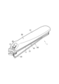
- FIG. 1 is a perspective view of a nail clipper.
- FIG. 2 is a side view of the nail clipper with the cutting edges engaged.
- FIG. 3 is an enlarged view of the vicinity of the blade tips of the nail clippers when the blade tips are engaged.
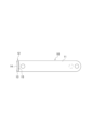
- FIG. 4 is a top view of the upper blade body.
- FIG. 5 is an enlarged view of the vicinity of the cutting edge of the upper blade body.
- FIG. 6 is an enlarged cross-sectional view of the vicinity of the cutting edge of the upper blade body of the modified example.
- the underside of the blade is curved in an arc so that the angle with respect to the vertical increases with distance from the cutting edge, and the angle between the front and back of the blade at the cutting edge is between 20° and 35°.
- the vertical direction here does not refer to the direction of gravity, which changes depending on the orientation of the nail clipper 1.
- Figs. 1 to 3 are diagrams of the nail clipper 1 of this embodiment, with Fig. 1 being a perspective view, Fig. 2 being a side view of the cutting edges engaged, and Fig. 3 being an enlarged view of the vicinity of the cutting edges in the same state.
- Figs. 4 and 5 are diagrams of the upper blade body 10 that constitutes the nail clipper 1, with Fig. 4 being a top view, and Fig. 5 being an enlarged cross-sectional view of the vicinity of the cutting edges at the center position in the width direction of the upper blade body 10.
- the nail clipper 1 comprises an upper blade body 10, a lower blade body 20, and an operating member 30.
- the operating member 30 comprises a lever 31 and a support shaft 32.
- the upper blade body 10 and the lower blade body 20 are connected by welding at the connecting portion 11a.
- the upper blade body 10 and the lower blade body 20 are further connected near their respective tips by the support shaft 32 so that the upper blade body 10 and the lower blade body 20 can move in directions toward and away from each other.
- the support shaft 32 is a cylindrical member, and the lever 31 is connected so as to be rotatable around the axis of the support shaft 32.
- the upper blade body 10 includes an upper body portion 11 and an upper tip portion 12.
- the upper body portion 11 is plate-shaped.
- the upper tip portion 12 is formed continuously from the upper body portion 11 and is bent toward the lower blade body 20 with respect to the upper tip portion 12.
- the upper tip portion 12 is formed with an upper bladed portion 13 that is sharpened by sharpening.
- the upper bladed portion 13 has a cutting edge 14 that is the tip of the blade.
- the upper tip portion 12 has a cutting surface 15 exposed to the outside and a cutting back surface 16 located on the back side of the cutting surface.
- the upper bladed portion 13 of the upper blade body 10 is curved in an arc shape with a recessed center at both ends in the width direction.
- the radius of curvature of this upper bladed portion 13 is, for example, 28 mm, but may be changed as desired.
- the upper body portion 11 has an outer surface 10a and an inner surface 10b.
- the inner surface 10b is located opposite the lower body portion 21 of the lower blade body 20, and the outer surface 10a is the surface opposite the inner surface 10b.
- the blade back connection portion 16b is also curved in an arc, and the radius of curvature is 0.1 mm to 2.0 mm, for example 1.0 mm.
- the radius of curvature of the blade back connection portion 16b is formed to be smaller than the radius of curvature of the curved portion 16a of the blade back 16.
- the blade surface 15 has a first blade surface 15a extending vertically from the cutting edge 14, a second blade surface 15b continuing from the first blade surface 15a, and a third blade surface 15c connecting the second blade surface 15b and the outer surface 10a.
- the second blade surface 15b extends in a direction forming an acute angle with respect to the vertical direction.
- the angle ⁇ 2 that the second blade surface 15b has with the outer surface 10a of the upper body portion 11 is preferably 55° or more and 75° or less, more preferably 60° or more and 70° or less, for example 65°.
- the third blade surface 15c is curved in an arc shape, and its radius of curvature is 1.0 mm or more and 4.0 mm or less, for example 2.8 mm.
- the distance L1 between the outer surface 10a and the cutting edge 14 is, for example, 3.0 mm or more and 6.0 mm or less, e.g., 4.6 mm.
- the angle ⁇ 1 between the cutting edge 15 and the cutting edge 16 is preferably 20° or more and 35° or less, more preferably 27° or more and 33° or less, for example 30°.
- the angle ⁇ 1 between the blade surface 15 and the blade back surface 16 is measured by measuring the angle between the tangent at the tip of the cutting edge 14 and the first blade surface 15a of the blade surface 15 on the curve formed by the blade back surface 16 on the cross section of the upper blade body 10.
- the lower blade body 20 has roughly the same shape as the upper blade body 10, but the shape is slightly different due to adjustments for meshing with the upper blade body 10, etc.
- the lower blade body 20 includes a lower body portion 21 and a lower tip portion 22.
- the lower body portion 21 is plate-shaped.
- the lower tip portion 22 is formed continuously with the lower body portion 21 and is bent toward the upper blade body 10 relative to the lower body portion 21.
- the lower tip portion 22 is formed with a lower bladed portion 23 that has been sharpened by sharpening.
- the lower bladed portion 23 has a cutting edge 24 that is the tip of the blade.
- a blade body that will be the base material for the upper blade body 10 and the lower blade body 20 is prepared.
- This base blade body is common to the upper blade body 10 and the lower blade body 20.
- the base blade body before processing is slightly different in shape from the upper blade body 10 and the lower blade body 20 that are completed through the steps below.
- the upper blade body 10 and the lower blade body 20 are connected by welding at the connecting portion 11a.
- the cutting edges 14 and 24 are formed by sharpening the respective tip portions.
- the front surfaces of the cutting edges 14 and 24 are formed on the same plane both before and after sharpening. Therefore, the cutting edge 14 of the upper blade body 10 and the cutting edge 24 of the lower blade body 20 can be sharpened simultaneously in a single sharpening process.
- the cutting edge 14 of the upper blade body 10 and the cutting edge 24 of the lower blade body 20 are slightly misaligned to form a "cover” that prevents the cutting edges from touching each other during use, and the angles of the upper blade body 10 and the lower blade body 20 are adjusted by "blade spread.”
- the operating member 30 is a member for operating the upper bladed portion 13 of the upper tip 12 and the lower bladed portion 23 of the lower tip 22 to move toward and away from each other.
- FIG. 6 is an enlarged view of the vicinity of the cutting edge of the upper blade body 110 of the nail clipper in the modified example, which corresponds to Fig. 5 of the embodiment.
- the cutting edge 116 of the modified example which corresponds to the cutting edge 16 is different in the curvature radius of the curved portion 116a and the cutting edge connecting portion 116b, and the angle with the cutting edge 15. The differences from the embodiment will be specifically described below.
- the blade back 116 has a curved portion 116a formed in the area from the cutting edge 14 to the blade back connection portion 116b, and the blade back connection portion 116b that connects the blade back 116 to the inner surface 10b of the upper body portion 11.
- the curved portion 116a and the blade back connection portion 116b are curved so that the angle with respect to the vertical direction increases with increasing distance from the cutting edge 14.
- the curved portion 116a is curved in an arc, with a radius of curvature of, for example, 7.6 mm.
- the blade back connection portion 116b is also curved in an arc, with a radius of curvature of, for example, 1.0 mm.
- the angle ⁇ 3 between the cutting edge 15 and the cutting edge 116 is, for example, 25°.
- the present invention is not limited to the configurations of the embodiments and modified examples, but also includes modifications based on the configurations of the embodiments and modified examples.
- the nail clippers 1 of the embodiment, the modified nail clippers, and the reference example nail clippers were prepared and evaluated by a number of people who actually used them.
- the reference example nail clippers were prepared with an angle of 40° between the blade surface and the blade back surface.
- the following description will refer to the nail clippers 1 of the embodiment as nail clippers A, the modified nail clippers as nail clippers B, and the reference example nail clippers as nail clippers C.
- the evaluation was carried out by multiple people on the quality of the cutting when cutting the nails and the sharpness of the blade, each on a four-point scale: 1. good, 2. fair, 3. slightly poor, and 4. poor.
- the quality of the cutting was determined by comprehensively assessing the cleanness of the cut edge when cutting the nails, the ease with which the separated nails were separated, and the occurrence of burrs.
- the sharpness was determined based on the degree to which the nails could be cut with light force.
- the quality of the cutting and the sharpness were calculated as the average of the four-point scale. In other words, the lower the value, the higher the evaluation.
- the blade back 16 is curved so that the angle with respect to the vertical direction increases as it moves away from the cutting edge 14 at the tip of the upper bladed portion 13, and the angle between the blade surface 15 and the blade back 16 at the cutting edge 14 of the upper bladed portion 13 is configured to be 20° or more and 35° or less. This configuration reduces the cutting resistance during use and allows the nail to be cut smoothly.
- the blade back 16 is curved rather than linear and the thickness of the upper tip portion 12 increases as it moves away from the cutting edge 14, it is possible to prevent the upper blade body 10 from bending or breaking. This makes it possible to provide a nail clipper that has sufficient performance for cutting nails and has increased durability.
- the angle between the front surface 15 of the blade and the back surface 16 of the blade is set to 27° or more and 33° or less, allowing the user to cut their nails without any stress.
- the underside of the blade 16 is curved into an arc with a radius of curvature of 5 mm to 50 mm, making the cutting edge 14 sufficiently sharp while ensuring sufficient durability of the cutting edge 14.
- the upper blade body 10 has an upper tip 12 bent toward the lower blade body 20 relative to the upper body 11.
- the second blade surface 15b which is continuous with the first blade surface 15a that includes the cutting edge 14 and extends horizontally in the vertical direction and extends linearly at an acute angle to the vertical direction, is formed to form an angle ⁇ 2 of 55° to 75° with the upper body 11.
- the blade back connection portion 16b is curved to have a smaller radius of curvature than the radius of curvature of the curved portion 16a of the blade back 16, making it relatively easy to mold, and is configured to sufficiently prevent the bent connection portion between the upper body portion 11 and the upper tip portion 12 from being damaged by stress.
- the above configurations are applied not only to the upper blade body 10 but also to the lower blade body 20, and it is more preferable to configure the upper blade body 10 and the lower blade body 20 as described above. However, a certain degree of effect can be obtained even if the above configuration is adopted only for the upper blade body 10 or the lower blade body 20.
Landscapes
- Life Sciences & Earth Sciences (AREA)
- Forests & Forestry (AREA)
- Engineering & Computer Science (AREA)
- Mechanical Engineering (AREA)
- Scissors And Nippers (AREA)
Priority Applications (1)
| Application Number | Priority Date | Filing Date | Title |
|---|---|---|---|
| CN202480016233.2A CN120857887A (zh) | 2023-03-16 | 2024-01-19 | 指甲刀 |
Applications Claiming Priority (2)
| Application Number | Priority Date | Filing Date | Title |
|---|---|---|---|
| JP2023-042344 | 2023-03-16 | ||
| JP2023042344A JP2024131863A (ja) | 2023-03-16 | 2023-03-16 | 爪切り |
Publications (1)
| Publication Number | Publication Date |
|---|---|
| WO2024190077A1 true WO2024190077A1 (ja) | 2024-09-19 |
Family
ID=92754803
Family Applications (1)
| Application Number | Title | Priority Date | Filing Date |
|---|---|---|---|
| PCT/JP2024/001465 Ceased WO2024190077A1 (ja) | 2023-03-16 | 2024-01-19 | 爪切り |
Country Status (3)
| Country | Link |
|---|---|
| JP (1) | JP2024131863A (https=) |
| CN (1) | CN120857887A (https=) |
| WO (1) | WO2024190077A1 (https=) |
Citations (4)
| Publication number | Priority date | Publication date | Assignee | Title |
|---|---|---|---|---|
| JPS50118076U (https=) * | 1974-03-13 | 1975-09-26 | ||
| JPH11169227A (ja) * | 1997-12-11 | 1999-06-29 | Kosaka Hamono Seisakusho:Kk | 爪切り |
| JP2018102408A (ja) * | 2016-12-22 | 2018-07-05 | 株式会社貝印刃物開発センター | 爪切り |
| WO2021177525A1 (ko) * | 2020-03-04 | 2021-09-10 | 로얄금속공업 주식회사 | 손톱깎이 |
-
2023
- 2023-03-16 JP JP2023042344A patent/JP2024131863A/ja active Pending
-
2024
- 2024-01-19 WO PCT/JP2024/001465 patent/WO2024190077A1/ja not_active Ceased
- 2024-01-19 CN CN202480016233.2A patent/CN120857887A/zh active Pending
Patent Citations (4)
| Publication number | Priority date | Publication date | Assignee | Title |
|---|---|---|---|---|
| JPS50118076U (https=) * | 1974-03-13 | 1975-09-26 | ||
| JPH11169227A (ja) * | 1997-12-11 | 1999-06-29 | Kosaka Hamono Seisakusho:Kk | 爪切り |
| JP2018102408A (ja) * | 2016-12-22 | 2018-07-05 | 株式会社貝印刃物開発センター | 爪切り |
| WO2021177525A1 (ko) * | 2020-03-04 | 2021-09-10 | 로얄금속공업 주식회사 | 손톱깎이 |
Also Published As
| Publication number | Publication date |
|---|---|
| CN120857887A (zh) | 2025-10-28 |
| JP2024131863A (ja) | 2024-09-30 |
Similar Documents
| Publication | Publication Date | Title |
|---|---|---|
| CN104097220B (zh) | 办公用剪刀 | |
| JP5624559B2 (ja) | 一体型かみそり刃及びこれを利用したカミソリカートリッジ | |
| JP2013240399A (ja) | 鋏 | |
| WO2008044538A1 (en) | Outer blade for reciprocation-type electric shaver and method of producing the same | |
| WO2024190077A1 (ja) | 爪切り | |
| WO2013021693A1 (ja) | 爪切り | |
| JP3155998U (ja) | まな板 | |
| HK40128303A (zh) | 指甲刀 | |
| WO2007081157A1 (en) | The manufacturing method for arc type clipper blade, and its nail clipper blade and its nail clipper | |
| KR20160062093A (ko) | 가위 | |
| KR200297625Y1 (ko) | 손톱깎이 | |
| JP2003062362A (ja) | 刃裏の凹曲を改良した鋏 | |
| WO2025132050A1 (en) | Personal grooming device | |
| JP5777243B2 (ja) | 爪切り | |
| JP3138480U (ja) | 条材カッタ | |
| JPH05317532A (ja) | 鋏の刀身構造 | |
| WO2025132049A1 (en) | Personal grooming device | |
| WO2025132053A1 (en) | Personal grooming device | |
| WO2025132040A1 (en) | Personal grooming device | |
| WO2025132048A1 (en) | Personal grooming device | |
| WO2025132051A1 (en) | Personal grooming device | |
| JPH10179947A (ja) | 鋏 | |
| JP6120600B2 (ja) | 爪切り | |
| JP2016189889A (ja) | 皮むき器 | |
| WO2026070086A1 (ja) | 穿刺針の製造方法 |
Legal Events
| Date | Code | Title | Description |
|---|---|---|---|
| 121 | Ep: the epo has been informed by wipo that ep was designated in this application |
Ref document number: 24770199 Country of ref document: EP Kind code of ref document: A1 |
|
| WWE | Wipo information: entry into national phase |
Ref document number: 202480016233.2 Country of ref document: CN |
|
| NENP | Non-entry into the national phase |
Ref country code: DE |
|
| WWP | Wipo information: published in national office |
Ref document number: 202480016233.2 Country of ref document: CN |
|
| 122 | Ep: pct application non-entry in european phase |
Ref document number: 24770199 Country of ref document: EP Kind code of ref document: A1 |