WO2024190045A1 - 発電用タービン - Google Patents
発電用タービン Download PDFInfo
- Publication number
- WO2024190045A1 WO2024190045A1 PCT/JP2023/046864 JP2023046864W WO2024190045A1 WO 2024190045 A1 WO2024190045 A1 WO 2024190045A1 JP 2023046864 W JP2023046864 W JP 2023046864W WO 2024190045 A1 WO2024190045 A1 WO 2024190045A1
- Authority
- WO
- WIPO (PCT)
- Prior art keywords
- working fluid
- turbine
- gap
- rotor blade
- axial direction
- Prior art date
- Legal status (The legal status is an assumption and is not a legal conclusion. Google has not performed a legal analysis and makes no representation as to the accuracy of the status listed.)
- Ceased
Links
Images





Classifications
-
- F—MECHANICAL ENGINEERING; LIGHTING; HEATING; WEAPONS; BLASTING
- F01—MACHINES OR ENGINES IN GENERAL; ENGINE PLANTS IN GENERAL; STEAM ENGINES
- F01D—NON-POSITIVE DISPLACEMENT MACHINES OR ENGINES, e.g. STEAM TURBINES
- F01D25/00—Component parts, details, or accessories, not provided for in, or of interest apart from, other groups
- F01D25/24—Casings; Casing parts, e.g. diaphragms, casing fastenings
- F01D25/26—Double casings; Measures against temperature strain in casings
-
- F—MECHANICAL ENGINEERING; LIGHTING; HEATING; WEAPONS; BLASTING
- F01—MACHINES OR ENGINES IN GENERAL; ENGINE PLANTS IN GENERAL; STEAM ENGINES
- F01D—NON-POSITIVE DISPLACEMENT MACHINES OR ENGINES, e.g. STEAM TURBINES
- F01D15/00—Adaptations of machines or engines for special use; Combinations of engines with devices driven thereby
- F01D15/10—Adaptations for driving, or combinations with, electric generators
-
- F—MECHANICAL ENGINEERING; LIGHTING; HEATING; WEAPONS; BLASTING
- F01—MACHINES OR ENGINES IN GENERAL; ENGINE PLANTS IN GENERAL; STEAM ENGINES
- F01D—NON-POSITIVE DISPLACEMENT MACHINES OR ENGINES, e.g. STEAM TURBINES
- F01D25/00—Component parts, details, or accessories, not provided for in, or of interest apart from, other groups
- F01D25/16—Arrangement of bearings; Supporting or mounting bearings in casings
Definitions
- the present disclosure relates to turbines for power generation.
- This application claims priority based on Japanese Patent Application No. 2023-040211, filed with the Japan Patent Office on March 15, 2023, the contents of which are incorporated herein by reference.
- Liquefied gas for example, liquefied natural gas
- liquefied natural gas is liquefied for the purpose of transportation and storage, and when it is supplied to destinations such as city gas and thermal power plants, it is heated and vaporized using a heat medium such as seawater.
- a heat medium such as seawater.
- the ORC Organic Rankine Cycle
- the ORC is known as a cold energy power generation cycle that uses liquefied natural gas.
- a low-temperature working fluid with a boiling point lower than that of water circulating in a closed loop is cooled and condensed with liquefied natural gas in a condenser, then pressurized by a pump, heated and evaporated in an evaporator using seawater or other heat sources, and this steam is introduced into a cold energy power generation turbine to generate power.
- Patent Document 1 discloses a cold energy power generation turbine in which two radial turbines and a generator are arranged coaxially within the same casing in order to reduce the size of the cold energy power generation device.
- the generator is located in the center of the shaft, and radial turbines are located at both ends of the shaft.
- At least one embodiment of the present disclosure aims to provide a power generation turbine that can cool a generator while minimizing the complexity and size of the structure.
- a power generating turbine includes: A rotating shaft; a generator including a rotor provided on one side of the rotating shaft in an axial direction and a stator disposed on an inner peripheral side of the rotor; at least one turbine blade provided on the other side of the rotating shaft in the axial direction relative to the generator; an inner casing configured to rotatably accommodate the rotating shaft, the inner casing having an opposing surface that faces a disk portion of the at least one turbine blade with a first gap therebetween, the inner casing forming a generator accommodating space that communicates with the first gap and accommodates the generator; an outer casing disposed on an outer circumferential side of the inner casing, communicating with the first gap between the outer casing and the inner casing to form a working fluid flow passage through which a working fluid of the turbine rotor blade flows;
- the inner casing is formed with at least one through hole having an outer opening formed on an outer surface that defines the working fluid flow path and an inner opening formed on an inner surface that defines the
- At least one embodiment of the present disclosure provides a power generation turbine that can cool a generator while minimizing the complexity and size of the structure.
- FIG. 1 is a schematic cross-sectional axial view of a power generating turbine according to an embodiment of the present disclosure
- FIG. 1 is a schematic cross-sectional axial view of a power generating turbine according to an embodiment of the present disclosure
- FIG. 1 is a schematic cross-sectional view, perpendicular to the axial direction, of a power generating turbine according to an embodiment of the present disclosure
- FIG. 1 is a schematic cross-sectional view along an axial direction near a turbine rotor blade of a power generating turbine according to an embodiment of the present disclosure
- FIG. 1 is a schematic cross-sectional view along an axial direction near a turbine rotor blade of a power generating turbine according to an embodiment of the present disclosure
- FIG. 1 is a schematic cross-sectional view along an axial direction near a turbine rotor blade of a power generating turbine according to an embodiment of the present disclosure
- FIG. 1 is a schematic cross-sectional axial view of a power generating turbine according to an embodiment of the present disclosure
- FIG. 1 is a schematic cross-sectional axial view of a power generating turbine according to an embodiment of the present disclosure
- FIG. 1 is a schematic cross-sectional view along the axial direction of a generator housing space and a bearing housing space of a power generating turbine according to an embodiment of the present disclosure.
- FIG. FIG. 1 is a schematic diagram of a power generation system including a power generating turbine according to an embodiment of the present disclosure.
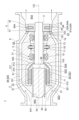
- FIGS. 1 and 2 are schematic cross-sectional views along the axial direction of a power generation turbine 1 according to an embodiment of the present disclosure.
- the direction in which the central axis CA of a rotating shaft 2 of the power generation turbine 1 extends is defined as the axial direction of the rotating shaft 2
- the direction perpendicular to the central axis CA is defined as the radial direction of the rotating shaft 2
- the circumferential direction around the central axis CA is defined as the circumferential direction of the rotating shaft 2.
- the axial direction, radial direction, and circumferential direction of the rotating shaft 2 may be simply referred to as the axial direction, radial direction, and circumferential direction, respectively.
- “along a certain direction” in this disclosure includes not only a certain direction, but also a direction inclined within a range of ⁇ 15° relative to a certain direction.
- the power generation turbine 1 comprises the rotating shaft 2, a generator 3 including a rotor 31 provided on one axial side (left side in the figure) of the rotating shaft 2 and a stator 32 provided on the inner circumferential side (radially inward) of the rotor 31, and at least one turbine blade 4 provided on the other axial side (right side in the figure) of the rotating shaft 2 relative to the generator 3.
- the one axial side and the other axial side of the rotating shaft 2 may be simply referred to as the one side and the other side, respectively.
- the rotor 31 includes a magnet support portion 311 that is cantilevered on the one end portion 21 of the rotating shaft 2, and a permanent magnet 312 that is supported from the outer periphery (radially outward) by the magnet support portion 311.
- the stator 32 has a stationary coil portion 321 that is disposed on the inner periphery side of the permanent magnet 312 so as to face the inner periphery side of the permanent magnet 312 with an inner periphery side gap S21 therebetween.
- the magnet support portion 311 includes a disk-shaped radial extension portion 313 whose inner end is mechanically connected to the end portion 21 on the one side of the rotating shaft 2 by fitting or the like and extends along the radial direction, and a cylindrical axial extension portion 314 that extends from the outer end of the radial extension portion 313 along the axial direction toward the one side in the axial direction.
- the radial extension portion 313 may include at least a portion of an inclined portion 315 that is inclined so as to shift toward the one side in the axial direction as it moves radially outward.
- the permanent magnet 312 is supported on the inner circumferential side of the axially extending portion 314.
- the stator 32 is disposed on the one side in the axial direction of the one end 21 of the rotating shaft 2, and is fixed relative to the rotation of the rotating shaft 2.
- the inner casing 5 includes a stator support portion 51 that supports the stator 32 from the inner circumferential side.
- the at least one turbine rotor blade 4 includes a first rotor blade 41 and a second rotor blade 42 provided on the other axial side of the rotating shaft 2 relative to the first rotor blade 41.
- the first rotor blade 41 and the second rotor blade 42 which are supported on the other side of the rotating shaft 2, have a short inter-blade distance, so that the pressure loss occurring between the rotor blades can be made small, thereby improving the performance of the power generation turbine 1.
- Each of the one-side rotor blade 41 and the other-side rotor blade 42 includes a disk portion 43, 45 whose inner circumferential end is attached to the other end of the rotating shaft 2 in the axial direction, protruding radially outward in a disk shape, and a blade portion 44, 46 provided on the outer periphery of the disk portion 43, 45.
- the power-generating turbine 1 further includes an inner casing 5 configured to rotatably house the rotating shaft 2, and an outer casing 6 arranged on the outer periphery (radially outward) of the inner casing 5.
- the inner casing 5 has an opposing surface 52 that faces the disk portion 43 of the one rotor blade 41 with a first gap S1 therebetween.
- the inner casing 5 forms therein a generator housing space S2 that houses the generator 3.
- the inner casing 5 is provided on one side of the rotating shaft 2 in the axial direction relative to the one-side rotor blade 41, and the opposing surface 52 is the end face of the inner casing 5 on the other side in the axial direction.
- the power-generating turbine 1 further includes at least one bearing 7 (in the illustrated example, a plurality of bearings) that are disposed between the generator 3 and the one rotor blade 41 in the axial direction of the rotating shaft 2 and rotatably support the rotating shaft 2.
- Each of the plurality of bearings 7 is made of a magnetic bearing that does not require lubricating oil, and is supported by the inner casing 5.
- the inner casing 5 defines therein a bearing accommodating space S3 that accommodates the rotating shaft 2 and the plurality of bearings 7, between the generator 3 and the one rotor blade 41 in the axial direction of the rotating shaft 2.
- the bearing accommodating space S3 is connected to the first gap S1 and the generator accommodating space S2, and communicates with the first gap S1 and the generator accommodating space S2.
- the rotating shaft 2 has a thrust disk portion 22 that protrudes radially outward from the rotating shaft 2 in the bearing accommodation space S3.
- the multiple bearings 7 include a one-side thrust bearing 71 that is arranged on one side of the rotating shaft 2 in the axial direction relative to the thrust disk portion 22 and faces the thrust disk portion 22 with a gap therebetween, and a other-side thrust bearing 72 that is arranged on the other side of the rotating shaft 2 in the axial direction relative to the thrust disk portion 22 and faces the thrust disk portion 22 with a gap therebetween.
- the multiple bearings 7 further include a one-side journal bearing 73 arranged between the generator 3 and the one-side thrust bearing 71 in the axial direction of the rotating shaft 2, and a second-side journal bearing 74 arranged between the other-side thrust bearing 72 and the one-side rotor blade 41 in the axial direction of the rotating shaft 2.
- the outer casing 6 is disposed on the outer periphery (radially outer side) of the inner casing 5, and forms a working fluid flow path S4 between the outer casing 6 and the inner casing 5, through which the working fluid of the turbine rotor blades 4 flows.
- the working fluid flow path S4 is formed by an inner circumferential surface 61 of the outer casing 6 and an outer circumferential surface 53 of the inner casing 5. The working fluid flowing through the working fluid flow path S4 is in a gaseous state.
- the working fluid flow path S4 includes an annular annular flow path S41 that surrounds the outer periphery of the generator accommodation space S2 and the bearing accommodation space S3, a columnar one-side columnar flow path S42 that is formed on the one side of the annular flow path S41 in the axial direction and extends along the axial direction, and a columnar other-side columnar flow path S43 that is formed on the other side of the annular flow path S41 in the axial direction and extends along the axial direction.
- Each of the one-side columnar flow path S42 and the other-side columnar flow path S43 is connected to the annular flow path S41 and communicates with the annular flow path S41.
- FIG. 3 is a schematic cross-sectional view perpendicular to the axial direction of the power generation turbine 1 according to an embodiment of the present disclosure.
- the inside of the generator accommodation space S2 is omitted.
- the power generation turbine 1 includes at least one casing support 11 that extends an annular flow path S41 along the radial direction of the rotating shaft 2.
- One end of the casing support 11 is connected to an inner circumferential surface 61 of the outer casing 6, and the other end is connected to an outer circumferential surface 53 of the inner casing 5.
- the inner casing 5 is supported by the outer casing 6 by the casing support 11.
- the first gap S1 is connected to a working fluid flow path S4 between one end of the one rotor blade 41 and the other end of the casing support 11, and communicates with the working fluid flow path S4.
- the casing support part 11 is arranged so that at least a portion of it overlaps with the generator storage space S2 in the axial direction, and is connected to the outer peripheral surface 53 of the inner casing 5, so that it also functions as a cooling fin to promote cooling of the generator 3. It is sufficient that at least one casing support part 11 is arranged along the axial direction, and it is sufficient that at least one is also arranged in the circumferential direction.
- the generator 3 provided on the other side of the rotating shaft 2 an outer rotor type
- a higher output density can be achieved and the radial size of the generator 3 and the generator housing space S2 can be reduced compared to when it is an inner rotor type.
- the working fluid flow path S4 formed on the outer periphery of the generator housing space S2 can be positioned relatively radially inward, preventing the power generation turbine 1 from becoming too large.
- the above-mentioned inner casing 5 is formed with at least one (in the illustrated example, multiple) through hole 54 having an outer opening 541 formed in an outer surface 55 that forms the working fluid flow path S4 and an inner opening 542 formed in an inner surface 56 that forms the generator accommodating space S2.
- the multiple through holes 54 are arranged at intervals from one another in the circumferential direction of the rotating shaft 2.
- each of the multiple through holes 54 is not limited to the illustrated embodiment, as long as the working fluid can flow between the generator storage space S2 and the outside of the inner casing 5.
- each of the multiple through holes 54 is formed in a straight line from the outer opening 541 to the inner opening 542, but is not limited to this shape.
- the outer opening 541 is formed on the end face on one side of the axial direction of the inner casing 5, but in other embodiments, it may be formed on the outer peripheral surface 53.
- the inner opening 542 is formed on the end face on the other side of the axial direction of the stator support part 51 extending along the axial direction, but it may be formed on a surface forming the generator storage space S2 other than the end face.
- the power generating turbine 1 includes at least one magnetic bearing 7 arranged between the generator 3 and one rotor blade 41 in the axial direction and configured to rotatably support the rotating shaft 2.
- the inner casing 5 described above has the above-mentioned bearing housing space S3 formed between the generator housing space S2 in the axial direction and the first gap S1, and connected to the generator housing space S2 and the first gap S1 to house the rotating shaft 2 and the magnetic bearing 7.
- the generator housing space S2 and the first gap S1 can allow the working fluid (bleed air) to flow through the bearing housing space S3, which houses the magnetic bearing 7 that does not require lubricating oil.
- the working fluid bleed air
- the bearing housing space S3 which houses the magnetic bearing 7 that does not require lubricating oil.
- the power generation turbine 1 is configured so that the working fluid flows through the working fluid flow path S4 from the other side to the one side in the axial direction.
- the blade portions 44, 46 of the one-side rotor blade 41 and the other-side rotor blade 42 are arranged in the working fluid flow path S4.
- the other-side rotor blade 42 is the first stage rotor blade
- the one-side rotor blade 41 is the second stage rotor blade.
- the power generation turbine 1 includes a first-side stator vane (second stage stator vane) 81 provided between the first-side rotor blade 41 and the second-side rotor blade 42, and a second-side stator vane (first stage stator vane) 82 provided on the other side in the axial direction of the second-side rotor blade 42.
- Each of the first-side stator vane 81 and the second-side stator vane 82 includes blade portions 83, 85 supported from the radially outer side by the inner circumferential surface 61 of the outer casing 6, and annular inner stator vane support portions 84, 86 that support the blade portions 83, 85 from the radially inner side.
- the main flow of the working fluid flowing through the working fluid flow passage S4 flows in the order of the other-side columnar flow passage S43, the annular flow passage S41, and the one-side columnar flow passage S42.
- the bleed air which is part of the working fluid flowing through the working fluid flow passage S4, flows in the order of the first gap S1, the bearing housing space S3, the generator housing space S2, the through hole 54, and the one-side columnar flow passage S42.
- the bleed air which is part of the working fluid that has passed through the turbine rotor blades 4, can flow into the generator housing space S2 through the first gap S1.
- the working fluid that flows into the generator housing space S2 expands and drops in temperature as it passes through the turbine rotor blades 4, so the generator 3 can be effectively cooled by the working fluid.
- the power generation turbine 1 described above further includes a resistor 12 that generates a pressure loss and is provided on the one axial side of the one rotor blade 41 in the working fluid flow path S4, as shown in FIG. 1.
- the resistor 12 generates a pressure loss in the working fluid flow path S4, thereby making the pressure in the working fluid flow path S4 between the resistor 12 and the one rotor blade 41 greater than the pressure in the bearing housing space S3.
- the casing support 11 also functions as a resistor 12. Measures for increasing the pressure loss in the working fluid flow path S4 using the casing support 11 include, for example, increasing the number or thickness of the casing support 11, or shifting one end of the casing support 11 in the axial direction in the circumferential direction relative to the other end.
- the resistor 12 may be a throttle section or the like that is provided in the working fluid flow path S4 and reduces the opening area of the working fluid flow path S4.
- the working fluid can be guided to the generator housing space S2 through the first gap S1 due to the pressure difference, and the working fluid can be discharged from the generator housing space S2 through the through hole 54.
- the working fluid since there is no need to separately provide a fan or the like for circulating the working fluid in the generator housing space S2, an increase in the number of pieces of equipment in the power generation turbine 1 can be suppressed, and an increase in the power consumption of the power generation turbine 1 can also be suppressed.
- the power generation turbine 1 is configured so that the working fluid flows through the working fluid flow path S4 from the one side to the other side in the axial direction.
- the blade portions 44, 46 of the one-side rotor blade 41 and the other-side rotor blade 42 are arranged in the working fluid flow path S4.
- the one-side rotor blade 41 is the first stage rotor blade
- the other-side rotor blade 42 is the second stage rotor blade.
- the power generation turbine 1 includes a first-side stator vane (first stage stator vane) 81A provided on the one side of the first-side rotor blade 41 in the axial direction, and a second-side stator vane (second stage stator vane) 82A provided between the first-side rotor blade 41 and the second-side rotor blade 42.
- the first-side stator vane 81A includes a blade portion 83A supported from the radial outside by the inner circumferential surface 61 of the outer casing 6 and supported from the radial inside by the outer circumferential surface 53 of the inner casing 5.
- the second-side stator vane 82A includes a blade portion 84A supported from the radial outside by the inner circumferential surface 61 of the outer casing 6, and an annular inner stator vane support portion 85A that supports the blade portion 84A from the radial inside.
- the main stream of the working fluid flowing through the working fluid flow path S4 flows in the order of the one-side columnar flow path S42, the annular flow path S41, and the other-side columnar flow path S43.
- the bleed air which is part of the working fluid flowing through the working fluid flow path S4, flows in the order of the through hole 54, the generator housing space S2, the bearing housing space S3, the first gap S1, and the other-side columnar flow path S43.
- the generator 3 can be cooled by allowing a portion of the working fluid before being introduced into the turbine rotor blades 4 to flow into the generator housing space S2 through the through holes 54. Then, by mixing the working fluid (bleed air) that has recovered thermal energy from the generator 3 and has increased enthalpy with the working fluid (main flow) introduced into the turbine rotor blades 4 through the first gap S1, the recovered power in the turbine rotor blades 4 can be increased, and the output of the power-generating turbine 1 can be increased.
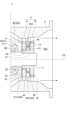
- FIG. 4 and Fig. 5 are schematic cross-sectional views along the axial direction near the turbine rotor blade 4 of the power generation turbine 1 according to one embodiment of the present disclosure.
- the power generation turbine 1 according to some embodiments includes the above-mentioned rotating shaft 2, the generator 3, the turbine rotor blade 4, the inner casing 5, and the outer casing 6, and the working fluid of the power generation turbine 1 is configured to flow through the working fluid flow path S4 from the one side to the other side in the axial direction.
- the disk portion 43 of the one-side rotor blade 41 described above has a first balance hole 48 penetrating in the axial direction.
- the first balance hole 48 is configured so that the working fluid (bleed air) guided from the bearing accommodation space S3 to the first gap S1 flows in.
- the working fluid (bleed air) guided from the bearing housing space S3 to the first gap S1 passes through the first balance hole 48 and then mixes with the working fluid (main flow) that has passed through the one-side rotor blade 41 between the one-side rotor blade 41 and the other-side rotor blade 42.
- the working fluid (bleed air) guided from the bearing accommodating space S3 to the first gap S1 passes through the first balance hole 48, and is mixed with the working fluid (main flow) that has passed through the one-side rotor blade 41 downstream in the flow direction of the working fluid from the one-side rotor blade 41 in which the first balance hole 48 is formed.
- the pressure loss when the bleed air and the main flow are mixed can be reduced compared to when the working fluid (bleed air) guided from the bearing accommodating space S3 to the first gap S1 is mixed with the working fluid introduced into the one-side rotor blade 41 through the first gap S1.
- the disk portion 43 of the one-side rotor blade 41 has a first balance hole 48 penetrating in the axial direction
- the disk portion 45 of the other-side rotor blade 42 has a second balance hole 49 penetrating in the axial direction.
- the first balance hole 48 is configured to receive the working fluid (bleed air) guided from the bearing accommodating space S3 to the first gap S1.
- the second balance hole 49 is formed radially outward of the rotating shaft 2 from the first balance hole 48, and is configured to receive the working fluid that has passed through the first balance hole 48.
- the working fluid (bleed air) guided from the bearing housing space S3 to the first gap S1 passes through the first balance hole 48 and the second balance hole 49, and then mixes with the working fluid (main flow) that has passed through the other rotor blade 42 in the other columnar flow passage S43.
- the turbine rotor blade 4 further includes a connecting portion 47 having one end connected to the disk portion 43 of the one rotor blade 41 and the other end connected to the disk portion 45 of the other rotor blade 42.
- the outer peripheral surface 471 of the connecting portion 47 faces the inner peripheral surface 851A of the inner stator vane support portion 85A described above with a gap therebetween.
- a seal structure 13 for sealing the gap between the outer peripheral surface 471 and the inner peripheral surface 851A is provided between the outer peripheral surface 471 of the connecting portion 47 and the inner peripheral surface 851A of the inner stator vane support portion 85A.
- the seal structure 13 is a labyrinth seal formed on the inner peripheral surface 851A.
- the gap between the outer peripheral surface 471 and the inner peripheral surface 851A is formed radially outward of the rotating shaft 2 from the first balance hole 48 and is formed radially inward of the rotating shaft 2 from the second balance hole 49.
- the first balance hole 48 described above passes through the gap between the outer peripheral surface 471 and the inner peripheral surface 851A, and then passes through the second balance hole 49.
- the working fluid (bleed air) that passes through the first balance hole 48 is pushed outward in the radial direction of the rotating shaft 2 due to the rotation of the rotating shaft 2.
- the working fluid (bleed air) that passes through the first balance hole 48 is more likely to flow into the second balance hole 49.
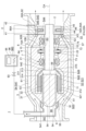
- FIGS. 6 and 7 are schematic cross-sectional views along the axial direction of a power generation turbine 1 according to one embodiment of the present disclosure.
- the power generation turbine 1 described above includes the rotating shaft 2, generator 3, turbine rotor blades 4, inner casing 5, and outer casing 6 described above, and the working fluid of the power generation turbine 1 is configured to flow through the working fluid flow path S4 from the one side to the other side in the axial direction.
- the power generation turbine 1 described above further includes an extraction line 9 having one end 91 connected to the outer opening 541 of at least one through hole 54 described above.
- the bleed line 9 has an internal flow passage 90 therein through which the working fluid flows.
- the outer openings 541 of each of the multiple through holes 54 are connected together to one end 91 arranged in the one-side columnar flow passage S42 and communicate with the internal flow passage 90.
- the working fluid (bleed air) introduced into the generator accommodating space S2 flows from the generator accommodating space S2 through the through holes 54 and into the bleed line 9.
- the working fluid (bleed air) flowing through the through holes 54 and the bleed line 9 is not mixed with the working fluid (main flow) flowing through the one-side columnar flow passage S42.
- the working fluid (extracted air) with increased enthalpy as a result of recovering thermal energy from the generator 3 can be recovered by the extraction line 9, and the enthalpy of the recovered working fluid (extracted air) can be used for a variety of purposes.
- the power generation turbine 1 may include a flow control valve 93 that is provided in the extraction line 9 and is configured to be able to adjust the flow rate of the working fluid flowing through the extraction line 9.
- the flow control valve 93 may be an on-off valve that can be adjusted to a fully closed or fully open position, or an opening control valve that can be adjusted to a fully closed or fully open position and at least one intermediate opening position therebetween.
- the power generation turbine 1 may include a heat exchanger 94 provided in the extraction line 9 and configured to recover thermal energy to the working fluid flowing through the extraction line 9.
- the object to be cooled is cooled by recovering thermal energy to the working fluid in the heat exchanger 94.
- the object to be cooled by the heat exchanger 94 may be, for example, a power electronics component 95 of the generator 3.
- the heat exchanger 94 and the power electronics component 95 are housed in an internal space 960 of a casing 96, and thermal energy generated by the power electronics component 95 is recovered to the working fluid in the heat exchanger 94.
- the rotating shaft 2 has the thrust disk portion 22.
- the magnetic bearing 7 includes the other-side thrust bearing 72.
- the inner casing 5 has at least one bleed hole 10.
- the bleed hole 10 has an outer opening 10A formed in the outer circumferential surface 53 that forms the annular flow path S41 (working fluid flow path S4) on the outer circumferential side of the bearing accommodating space S3, and an inner opening 10B formed in the inner surface 57 that forms the bearing accommodating space S3 on the other side in the axial direction than the other-side thrust bearing 72.
- the bleed hole 10 is not limited to the embodiment shown in the figure, as long as the working fluid can flow between the annular flow passage S41 and the bearing housing space S3.
- the bleed hole 10 is formed in a straight line along the radial direction from the outer opening 10A to the inner opening 10B, but is not limited to this shape.
- a portion of the working fluid (main flow) introduced into the turbine rotor blade 4 can be made to flow into the bearing housing space S3 through the bleed hole 10.
- the working fluid (bleed air) that flows into the bearing housing space S3 is divided into one-side bleed air that flows through the bearing housing space S3 toward the one side in the axial direction, and the other-side bleed air that flows through the bearing housing space S3 toward the other side in the axial direction.
- the one-side bleed air flows in the following order: the one side in the axial direction from the bleed hole 10 of the bearing accommodation space S3, the generator accommodation space S2, the through hole 54, and the bleed line 9.
- the other-side bleed air flows in the following order: the other side in the axial direction from the bleed hole 10 of the bearing accommodation space S3, the first gap S1, and the first space S44 between the one-side stator vane 81A and the one-side rotor blade 41 in the working fluid flow path S4.
- the above configuration allows a portion of the working fluid (main flow) introduced into the turbine rotor blades 4 to flow into the generator housing space S2 through the bleed hole 10 located upstream of the first gap S1 in the flow direction of the working fluid flow passage S4.
- the thrust disk portion 22 is pushed from the other side to the one side by the working fluid (one-side bleed) flowing through the generator housing space S2 from the other side to the one side in the axial direction, thereby reducing the thrust force on the rotating shaft 2.
- the at least one turbine rotor blade 4 includes the one-side rotor blade 41 and the other-side rotor blade 42.
- the power generation turbine 1 further includes a one-side stator blade 81A arranged on the one side in the axial direction from the one-side rotor blade 41 and the first gap S1, and the other end 92 (92A, 92B) of the above-mentioned extraction line 9 is connected to either the first space S44 between the one-side stator blade 81A and the one-side rotor blade 41 in the working fluid flow path S4, or the second space S45 on the other side from the other-side rotor blade 42 in the working fluid flow path S4.
- the other end 92 (92A, 92B) of the extraction line 9 is connected to the first space S44 or the second space S45 from the outside in the radial direction.
- the working fluid (bleed air) introduced into the extraction line 9 is led to the first space S44 or the second space S45.
- the working fluid (bleed air) that has cooled the generator 3 is mixed with the working fluid (main flow) that has passed through the other rotor blade 42 in the second space S45.
- the pressure loss when the bleed air and the main flow are mixed can be reduced compared to when the bleed air is mixed with the main flow introduced into the turbine rotor blade 4.
- the at least one turbine rotor blade 4 described above includes the one-side rotor blade 41 described above and the other-side rotor blade 42 described above.
- the power generation turbine 1 further includes a one-side stator vane 81A arranged on the one side in the axial direction relative to the one-side rotor blade 41 and the first gap S1, and the other end 92 (92A) of the above-mentioned extraction line 9 is connected to the second space S45 on the other side of the other-side rotor blade 42 in the working fluid flow path S4.
- the other end 92 (92A) of the extraction line 9 is connected to the second space S45 from the outside in the radial direction.
- the working fluid (bleed air) introduced into the extraction line 9 is led to the second space S45.
- the working fluid (bleed air) that has cooled the generator 3 is mixed with the working fluid (main flow) that has passed through the other rotor blade 42 in the second space S45.
- the pressure loss when the bleed air and the main flow are mixed can be reduced compared to when the bleed air is mixed with the main flow introduced into the turbine rotor blade 4.
- FIG. 8 is a schematic cross-sectional view along the axial direction near the generator housing space S2 and the bearing housing space S3 of the power generation turbine 1 according to one embodiment of the present disclosure. Although the first throttling portion A1 and the second throttling portion A2 are depicted in Fig. 8, it is sufficient if either the first throttling portion A1 or the second throttling portion A2 is present. In the power generation turbine 1 according to some embodiments, as shown in Fig.
- the rotating shaft 2 has the thrust disk portion 22, and the first throttling portion A1 that narrows the flow path of the working fluid is provided between the outer circumferential surface 221 of the thrust disk portion 22 and the inner surface 58 of the inner casing 5 that faces the outer circumferential surface 221 with a gap therebetween.
- the thrust disk portion 22 is pushed from the other side to the one side by the pressure difference generated between the one side and the other side in the axial direction of the first throttling portion A1 of the bearing housing space S3, thereby reducing the thrust force on the rotating shaft 2.
- the first throttling portion A1 upstream of the generator housing space S2 in the flow direction of the bleed air the rotor 31 of the generator 3 rotates in a relatively low pressure field, thereby reducing windage loss of the rotor 31.
- a second throttling section A2 that narrows the flow path of the working fluid is provided between the outer peripheral surface 33 of the rotor 31 and the inner surface (inner peripheral surface) 56A of the inner casing 5 that faces the outer peripheral surface 33 with a gap therebetween.
- the second throttling portion A2 is provided on the other side in the axial direction.
- the second throttling portion A2 is provided on the other side in the axial direction relative to the permanent magnet 312.
- the thrust bearing can be made smaller than when the first throttling portion A1 is provided, thereby preventing the power generation turbine 1 from becoming larger.
- the inner casing 5 of the power generation turbine 1 includes the stator support portion 51 that supports the stator 32 from the inner circumferential side.
- the generator accommodating space S2 includes an outer circumferential gap S22, an inner circumferential gap S21, a one-side space S23, and an other-side space S24.
- the outer circumferential gap S22 is formed between the outer circumferential surface 33 of the rotor 31 and the inner surface 56A of the inner casing 5 that faces the outer circumferential surface 33 with a gap on the outer circumferential side.
- the inner circumferential gap S21 is formed between the rotor 31 and the stator 32.
- the one-side space S23 is connected to the outer circumferential gap S22 and the inner circumferential gap S21 on the one side in the axial direction, further than the inner circumferential gap S21.
- the one-side space S23 is formed by the inner surface on the one side that forms the generator accommodating space S2 of the inner casing 5.
- the other side space S24 is connected to the inner circumferential gap S21 on the other side in the axial direction of the inner circumferential gap S21.
- the other side space S24 is formed by the rotor 31 and the stator support part 51.
- the inner opening 542 of each of the plurality of through holes 54 described above is connected to the other side space S24.
- the working fluid (bleed air) introduced into the generator housing space S2 passes through the outer peripheral gap S22, the one-side space S23, the inner peripheral gap S21, and the other-side space S24 in that order or in reverse order, so that the rotor 31 and the stator 32 can be effectively cooled as they pass through the generator housing space S2.
- Power generation system 9 is a schematic diagram of a power generation system 100 including a power generation turbine 1 according to an embodiment of the present disclosure.
- the power generation system 100 is for recovering cold energy contained in the liquefied gas as electric power via a heat medium for heating the liquefied gas.
- the liquefied gas is vaporized, the cold energy is recovered as electric power by the power generation turbine 1 mounted on the power generation system 100.
- the power generation system 100 includes a power generation turbine 1, a heat medium circulation line 101, a liquefied gas supply line 102, a condenser 103, a heating fluid supply line 104, a cold heat pump 105, and an evaporator 106.
- the power generation turbine 1, the condenser 103, the cold heat pump 105, and the evaporator 106 are each connected to the heat medium circulation line 101.
- the liquefied gas supply line 102 is connected to the condenser 103.
- the heating fluid supply line 104 is connected to the evaporator 106.
- Each of the heat medium circulation line 101, the liquefied gas supply line 102, and the heating fluid supply line 104 includes a flow path, such as a pipe, through which a fluid flows.
- the power generation system 100 is configured to be driven by the heat medium circulating in the heat medium circulation line 101 while changing its state to liquid or gas.
- the heat medium circulation line 101 is configured to circulate a heat medium having a lower freezing point than water.
- liquefied natural gas LNG
- propane will be used as a specific example of a heat medium flowing through the heat medium circulation line 101.
- the present disclosure is also applicable to liquefied gases other than liquefied natural gas (such as liquefied hydrogen), and is also applicable to cases where a heat medium other than propane, such as R1234yf or R1234ze, is used as a heat medium flowing through the heat medium circulation line 101.
- the condenser 103 is configured to condense the working fluid by heat exchange between the heat medium and the liquefied gas. Inside the condenser 103, there are provided a heating side pipe 103A connected to the heat medium circulation line 101 and into which the heat medium circulating through the heat medium circulation line 101 flows, and a heated side pipe 103B connected to the liquefied gas supply line 102 and into which the liquefied gas flowing through the liquefied gas supply line 102 flows.
- the heat medium flowing through the heating side pipe 103A and the liquefied gas flowing through the heated side pipe 103B are configured to exchange heat.
- the heat medium is cooled and condensed by the heat exchange, and the liquefied gas is heated.
- the liquefied gas supply line 102 upstream of the condenser 103 is connected to a liquefied gas pump 102A, and the further upstream side of the liquefied gas pump 102A is connected to a liquefied gas storage device 102B.
- the liquid liquefied gas stored in the liquefied gas storage device 102B is sent to the liquefied gas supply line 102, flows through the liquefied gas supply line 102 from the upstream side to the downstream side, and is supplied to the condenser 103.
- the liquefied gas vaporized by heat exchange inside the condenser 103 flows through the heated side pipe 103B, and then flows again through the liquefied gas supply line 102, and is supplied as fuel to an engine (not shown) installed downstream of the condenser 103.
- the cold heat pump 105 is configured to boost the pressure of the heat medium supplied from the condenser 103.
- the heat medium circulates through the heat medium circulation line 101.
- the heat medium flows from the condenser 103 to the cold heat pump 105, from the cold heat pump 105 to the evaporator 106, from the evaporator 106 to the power generation turbine 1, and from the power generation turbine 1 to the condenser 103.
- the cold/heat pump 105 may be of any type as long as it can boost the pressure of the heat medium.
- a turbo pump centrifugal pump, mixed flow pump, axial flow pump, etc.
- a positive displacement pump reciprocating pump, rotary pump
- a special pump submersible motor pump
- the evaporator 106 is configured to evaporate the heat medium by heat exchange between the heat medium pressurized by the cold heat pump 105 and the heating fluid introduced from outside the power generation system 100.
- Inside the evaporator 106 there are a heat medium heated side pipe 106A into which the heat medium pressurized by the cold heat pump 105 flows and which is connected to the heat medium circulation line 101, and a heat medium heating side pipe 106B into which the heating fluid introduced from outside the power generation system 100 flows, which is connected to the heating fluid supply line 104.
- the heat medium flowing through the heat medium heated side pipe 106A and the heating fluid flowing through the heat medium heating side pipe 106B are configured to exchange heat.
- the heat medium is heated and evaporated by the heat exchange, and the heating fluid is cooled.
- the heated fluid supply line 104 upstream of the evaporator 106 is connected to a heated fluid pump 104A.
- the heated fluid supply line 104 further upstream of the heated fluid pump 104A is connected to a heating fluid supply source so that heated fluid can be introduced from outside the power generation system 100.
- the heating fluid is sent from the heating fluid supply source to the heating fluid supply line 104, flows through the heating fluid supply line 104 from the upstream side to the downstream side, and is supplied to the evaporator 106.
- the heating fluid is cooled by heat exchange inside the evaporator 106, flows through the heat medium heating side pipe 106B, and then flows again through the heating fluid supply line 104, and is discharged outside the power generation system 100.
- heating fluid may be any fluid that heats the heat medium circulating in the heat medium circulation line 101 as a heat medium in the evaporator 106, and may be steam, hot water, seawater, engine cooling water, or water at room temperature.
- the power generation turbine 1 is configured to be driven by the gaseous heat medium generated in the evaporator 106.
- the power generation turbine 1 has the generator 3 described above.
- the power generation turbine 1 is configured to drive the generator 3 by rotating the rotating shaft 2 of the power generation turbine 1 with the gaseous heat medium generated in the evaporator 106.
- the gaseous heat medium that drives the power generation turbine 1 flows through the heat medium circulation line 101 toward the condenser 103 described above, which is installed downstream of the power generation turbine 1.
- the power generation turbine 1 is provided in a heat medium circulation line 101 configured to circulate a heat medium for heating the liquefied gas.
- the heat medium circulating through the heat medium circulation line 101 and introduced into the power generation turbine 1 is at a relatively low temperature due to the recovery of the cold energy of the liquefied gas.
- a relatively low-temperature working fluid is introduced into the generator housing space S2, so that the generator 3 is effectively cooled.
- expressions expressing relative or absolute configuration do not only strictly represent such a configuration, but also represent a state in which there is a relative displacement with a tolerance or an angle or distance to the extent that the same function is obtained.
- expressions indicating that things are in an equal state such as “identical,””equal,” and “homogeneous,” not only indicate a state of strict equality, but also indicate a state in which there is a tolerance or a difference to the extent that the same function is obtained.
- expressions describing shapes such as a rectangular shape or a cylindrical shape do not only refer to shapes such as a rectangular shape or a cylindrical shape in the strict geometric sense, but also refer to shapes that include uneven portions, chamfered portions, etc., to the extent that the same effect can be obtained.
- the expressions "comprise,””include,” or “have” a certain element are not exclusive expressions that exclude the presence of other elements.
- a power generating turbine (1) comprises: A rotating shaft (2); a generator (3) including a rotor (31) provided on one side of the rotating shaft (2) in the axial direction and a stator (32) arranged on an inner peripheral side of the rotor (31); At least one turbine blade (4) provided on the other side of the rotating shaft (2) in the axial direction relative to the generator (3); an inner casing (5) configured to rotatably accommodate the rotating shaft (2), the inner casing (5) having an opposing surface (52) opposing a disk portion (43) of the at least one turbine rotor blade (4) with a first gap (S1) therebetween, the inner casing (5) forming a generator accommodating space (S2) communicating with the first gap (S1) and accommodating the generator (3); an outer casing (6) disposed on an outer circumferential side of the inner casing (5) and communicating with the first gap (S1) between the outer casing (6) and the inner casing (5) to form a working fluid flow path (S4) through which a working fluid of
- the generator (3) provided on the other side of the rotating shaft (2) an outer rotor type
- a higher power density can be achieved and the radial size of the generator (3) and the generator housing space (S2) can be reduced compared to when it is an inner rotor type.
- This allows the working fluid flow path (S4) formed on the outer periphery of the generator housing space (S2) to be positioned relatively radially inward, thereby preventing the power generation turbine (1) from becoming too large.
- a portion of the working fluid flowing through the working fluid passage (S4) can be bled into the generator housing space (S2) via the first gap (S1) and the through hole (54), and can be discharged from the generator housing space (S2) after cooling the generator (3). Since the generator (3) can be cooled by such a simple structure, the complexity of the power generation turbine (1) can be suppressed.
- the power generating turbine (1) according to 1) above, at least one magnetic bearing (7) arranged between the generator (3) and the at least one turbine blade (4) in the axial direction and configured to rotatably support the rotating shaft (2);
- the inner casing (5) is formed between the generator accommodating space (S2) and the first gap (S1) in the axial direction, and a bearing accommodating space (S3) is formed which is connected to the generator accommodating space (S2) and the first gap (S1) and accommodates the rotating shaft (2) and the at least one magnetic bearing (7).
- the generator housing space (S2) and the first gap (S1) can allow the working fluid (bleed air) to flow through the bearing housing space (S3), which houses the magnetic bearing (7) that does not require lubrication.
- the bearing housing space (S3) which houses the magnetic bearing (7) that does not require lubrication.
- the power generating turbine (1) according to 2) above The working fluid is configured to flow through the working fluid flow path (S4) from the other side to the one side in the axial direction.
- a portion of the working fluid that has passed through the turbine rotor blades (4) can be made to flow into the generator housing space (S2) through the first gap (S1).
- the working fluid that flows into the generator housing space (S2) expands and has a lowered temperature as it passes through the turbine rotor blades (4), so the generator (3) can be effectively cooled by the working fluid.
- the power generating turbine (1) according to 2) above The working fluid is configured to flow through the working fluid flow path (S4) from the one side to the other side in the axial direction.
- the generator (3) can be cooled by allowing a portion of the working fluid before being introduced into the turbine rotor blades (4) to flow into the generator housing space (S2) through the through hole (54). Then, by mixing the working fluid with increased enthalpy as a result of recovering thermal energy from the generator (3) with the working fluid introduced into the turbine rotor blades (4) through the first gap (S1), the recovered power in the turbine rotor blades (4) can be increased, and the output of the power-generating turbine (1) can be increased.
- the rotor blade (4) is provided with a resistor (12) for generating a pressure loss, the resistor (12) being provided on one side of the at least one turbine blade (4) in the axial direction in the working fluid flow path (S4), and for making the pressure in the working fluid flow path between the resistor (12) and the at least one turbine blade (4) greater than the pressure in the bearing accommodating space (S3).
- a resistor (12) is provided in the working fluid flow path (S4) and the pressure of the working fluid flow path between the resistor (12) and the turbine rotor blades (4) is made higher than the pressure in the bearing housing space (S3), so that the working fluid can be guided to the generator housing space (S2) through the first gap (S1) by the pressure difference, and the working fluid can be discharged from the generator housing space (S2) through the through hole (54).
- the working fluid since there is no need to separately provide a fan or the like for circulating the working fluid in the generator housing space (S2), it is possible to suppress an increase in the number of pieces of equipment in the power generation turbine (1) and also suppress an increase in the power consumption of the power generation turbine (1).
- the first balance hole (48) is configured so that the working fluid introduced from the bearing accommodating space (S3) to the first gap (S1) flows into it.
- the working fluid (bleed air) guided from the bearing housing space (S3) to the first gap (S1) passes through the first balance hole (48) and is mixed with the working fluid (main flow) that has passed through the turbine rotor blade (4) in which the first balance hole (48) is formed, downstream of the turbine rotor blade (4) in which the first balance hole (48) is formed in the flow direction of the working fluid.
- the pressure loss when the bleed air and the main flow are mixed can be reduced compared to the case where the working fluid (bleed air) guided from the bearing housing space (S3) to the first gap (S1) is mixed with the working fluid introduced into the turbine rotor blade (4) through the first gap (S1).
- the at least one turbine blade (4) comprises: A blade (41) on one side having the first balance hole (48); a second rotor blade (42) provided on the second side in the axial direction relative to the first rotor blade (41), The disk portion (45) of the other rotor blade (42) has a second balance hole (49) penetrating therethrough in the axial direction,
- the second balance hole (49) is formed radially outward of the rotating shaft (2) relative to the first balance hole (48) and is configured so that the working fluid that has passed through the first balance hole (48) flows into the second balance hole (49).
- the working fluid (bleed air) that has passed through the first balance hole (48) is pushed outward in the radial direction of the rotating shaft (2) by the rotation of the rotating shaft (2).
- the working fluid (bleed air) that has passed through the first balance hole (48) is more likely to flow into the second balance hole (49).
- the at least one through hole (54) further includes a bleed line (9) having one end (91) connected to the outer opening (541) of the at least one through hole (54).
- the working fluid (bleed air) with increased enthalpy as a result of recovering thermal energy from the generator (3) can be recovered by the bleed line (9), and the enthalpy of the recovered working fluid (bleed air) can be used for a variety of purposes.
- the power generating turbine (1) according to 8) above, And,
- the rotating shaft (2) has a thrust disk portion (22) protruding radially outward of the rotating shaft (2) in the bearing accommodating space (S3),
- the at least one magnetic bearing (7) includes a second-side thrust bearing (72) that is disposed on the second side in the axial direction of the rotating shaft (2) relative to the thrust disk portion (22) and faces the thrust disk portion (22) with a gap therebetween;
- the inner casing (5) is formed with at least one bleed hole (10) having an outer opening (10A) formed in an outer peripheral surface (53) which forms the working fluid flow path (S4) on the outer peripheral side of the bearing accommodating space (S3), and an inner opening (10B) formed in an inner surface (57) which forms the bearing accommodating space (S3) on the other side in the axial direction relative to the other-side thrust bearing (72).
- a portion of the working fluid introduced into the turbine rotor blades (4) can be made to flow into the generator housing space (S2) through the bleed hole (10) located upstream of the first gap (S1) in the flow direction of the working flow passage.
- the thrust disk portion (22) is pushed from the other side to the one side by the working fluid (bleed air) flowing through the generator housing space (S2) from the other side to the one side in the axial direction, thereby reducing the thrust force applied to the rotating shaft (2).
- the at least one turbine blade (4) comprises: One rotor blade (41), a second rotor blade (42) provided on the second side in the axial direction relative to the first rotor blade (41),
- the power generating turbine (1) comprises: a one-side stator vane (81A) arranged on the one side in the axial direction relative to the one-side rotor blade (41) and the first gap (S1),
- the other end (92) of the extraction line (9) is connected to either a first space (S44) between the one-side stator vane (81A) and the one-side rotor blade (41) in the working fluid flow path (S4), or a second space (S45) on the other side of the other-side rotor blade (42).
- the at least one turbine blade (4) comprises: One rotor blade (41), a second rotor blade (42) provided on the second side in the axial direction relative to the first rotor blade (41),
- the power generating turbine (1) comprises: a one-side stator vane (81A) arranged on the one side in the axial direction relative to the one-side rotor blade (41) and the first gap (S1),
- the other end (92) of the extraction line (9) is connected to a second space (S45) on the other side of the other rotor blade (42) in the working fluid flow path (S4).
- the working fluid (bleed air) that has cooled the generator (3) is mixed with the working fluid (main flow) that has passed through the other rotor blade (42) in the second space (S45).
- the pressure loss when the bleed air and the main flow are mixed can be reduced compared to when the bleed air is mixed with the main flow introduced into the turbine rotor blade (4).
- the power generation turbine (1) according to any one of 8) to 11) above,
- the rotating shaft (2) has a thrust disk portion (22) protruding radially outward of the rotating shaft (2) in the bearing accommodating space (S3),
- a first throttling section (A1) that narrows the flow path of the working fluid is provided between an outer peripheral surface (221) of the thrust disk section (22) and an inner surface (58) of the inner casing (5) that faces the outer peripheral surface (221) of the thrust disk section (22) with a gap therebetween.
- the thrust disk portion (22) is pushed from the other side to the one side by the pressure difference generated between the one side and the other side in the axial direction of the first throttling portion (A1) of the bearing accommodation space (S3), thereby reducing the thrust force on the rotating shaft (2).
- the first throttling portion (A1) upstream of the generator accommodation space (S2) in the flow direction of the bleed air the rotor (31) of the generator (3) rotates in a relatively low pressure field, thereby reducing windage loss of the rotor (31).
- a second throttling section (A2) that narrows the flow path of the working fluid is provided between the outer peripheral surface (33) of the rotor (31) and the inner surface (56A) of the inner casing (5) that faces the outer peripheral surface (33) of the rotor (31) with a gap therebetween.
- the thrust bearing can be made smaller than when the first throttling portion (A1) is provided, thereby preventing the power generation turbine (1) from becoming larger.
- the inner casing (5) includes a stator support portion (51) that supports the stator from an inner peripheral side
- the generator accommodation space (S2) is an outer circumferential gap (S22) formed between an outer circumferential surface of the rotor (31) and an inner surface of the inner casing (5) facing the outer circumferential surface of the rotor (31) with a gap on the outer circumferential side; an inner peripheral gap (S21) formed between the rotor (31) and the stator (32); a one-side space (S23) connected to the outer circumferential side gap (S22) and the inner circumferential side gap (S21) on the one side in the axial direction relative to the inner circumferential side gap (S21); a second-side space (S24) connected to the inner-periphery-side gap (S21) on the other side in the axial direction relative to the inner-periphery-side gap (S21), the second-side
- the working fluid (bleed air) introduced into the generator housing space (S2) passes through the outer circumferential gap (S22), the one-side space (S23), the inner circumferential gap (S21), and the other-side space (S24) in that order or in reverse order, so that the rotor (31) and the stator (32) can be effectively cooled as they pass through the generator housing space (S2).
- the power generating turbine (1) according to any one of 1) to 14) above, The power generation turbine (1) was provided in a heat medium circulation line (101) configured to circulate a heat medium for heating liquefied gas.
- the heat medium circulating through the heat medium circulation line (101) and introduced into the power generation turbine (1) is at a relatively low temperature by recovering the cold energy of the liquefied gas.
- a relatively low-temperature working fluid is introduced into the generator housing space (S2), so that the generator (3) is effectively cooled.
Landscapes
- Engineering & Computer Science (AREA)
- Mechanical Engineering (AREA)
- General Engineering & Computer Science (AREA)
- Connection Of Motors, Electrical Generators, Mechanical Devices, And The Like (AREA)
Abstract
Description
本願は、2023年3月15日に日本国特許庁に出願された特願2023-040211号に基づき優先権を主張し、その内容をここに援用する。
回転シャフトと、
前記回転シャフトの軸方向の一方側に設けられるロータ及び前記ロータの内周側に配置されるステータを含む発電機と、
前記発電機よりも前記回転シャフトの前記軸方向の他方側に設けられる少なくとも1つのタービン動翼と、
前記回転シャフトを回転可能に収容するように構成された内側ケーシングであって、前記少なくとも1つのタービン動翼のディスク部に第1隙間を有して対向する対向面を有し、前記第1隙間に連通して前記発電機を収容する発電機収容空間を形成する内側ケーシングと、
前記内側ケーシングの外周側に配置され、前記内側ケーシングとの間に前記第1隙間に連通して前記タービン動翼の作動流体が流れる作動流体流路を形成する外側ケーシングと、を備え、
前記内側ケーシングは、前記作動流体流路を形成する外面に形成された外側開口及び前記発電機収容空間を形成する内面に形成された内側開口を有する少なくとも1つの貫通孔が形成された。
図1及び図2の各々は、本開示の一実施形態に係る発電用タービン1の軸方向に沿った概略断面図である。以下、発電用タービン1の回転シャフト2の中心軸線CAが延在する方向を回転シャフト2の軸方向と定義し、中心軸線CAに直交する方向を回転シャフト2の径方向と定義し、中心軸線CA回りの周方向を回転シャフト2の周方向と定義する。本開示において、回転シャフト2の軸方向、径方向、周方向の各々を単に軸方向、径方向、周方向と云うことがある。なお、本開示における「或る方向に沿って」とは、或る方向だけでなく、或る方向に対して±15°以内の範囲において傾斜する方向をも含むものである。
ロータ31は、回転シャフト2の上記一方側の端部21に片持ち支持される磁石支持部311と、磁石支持部311に外周側(径方向外側)から支持される永久磁石312と、を含む。ステータ32は、永久磁石312の内周側に内周側隙間S21を有して対向するように配置された静止コイル部321を有する。
図示される実施形態では、上述した少なくとも1つのタービン動翼4は、一方側動翼41と、一方側動翼41よりも回転シャフト2の軸方向の他方側に設けられる他方側動翼42と、を含む。回転シャフト2の上記他方側にそれぞれ支持される一方側動翼41及び他方側動翼42は、動翼間距離が短いため、動翼間に生じる圧力損失を小さなものとすることができ、ひいては発電用タービン1の性能向上が図れる。
発電用タービン1は、図1~図3に示されるように、回転シャフト2を回転可能に収容するように構成された内側ケーシング5と、内側ケーシング5の外周側(径方向外側)に配置される外側ケーシング6と、をさらに備える。内側ケーシング5は、一方側動翼41のディスク部43に第1隙間S1を有して対向する対向面52を有する。内側ケーシング5は、発電機3を収容する発電機収容空間S2を内部に形成する。
発電用タービン1は、図1~図3に示されるように、回転シャフト2の軸方向における発電機3と一方側動翼41の間に配置され、回転シャフト2を回転可能に支持する少なくとも1つ(図示例では、複数)の軸受7をさらに備える。複数の軸受7の各々は、潤滑油が不要な磁気軸受からなり、内側ケーシング5に支持されている。内側ケーシング5は、回転シャフト2の軸方向における発電機3と一方側動翼41の間に、回転シャフト2及び複数の軸受7を収容する軸受収容空間S3を内部に形成する。軸受収容空間S3は、第1隙間S1及び発電機収容空間S2に接続され、第1隙間S1及び発電機収容空間S2に連通している。
外側ケーシング6は、図1~図3に示されるように、内側ケーシング5の外周側(径方向外側)に配置され、内側ケーシング5との間にタービン動翼4の作動流体が流れる作動流体流路S4を形成する。作動流体流路S4は、外側ケーシング6の内周面61及び内側ケーシング5の外周面53により形成される。作動流体流路S4を流れる作動流体は、ガス状になっている。
図3は、本開示の一実施形態に係る発電用タービン1の軸方向に直交する概略断面図である。図3では、発電機収容空間S2の内部を省略して示している。図1~図3に示される実施形態では、発電用タービン1は、環状流路S41を回転シャフト2の径方向に沿って延在する少なくとも1つのケーシング支持部11を備える。ケーシング支持部11は、一端が外側ケーシング6の内周面61に接続され、他端が内側ケーシング5の外周面53に接続される。ケーシング支持部11により、内側ケーシング5は、外側ケーシング6に支持されている。第1隙間S1は、一方側動翼41の一方端とケーシング支持部11の他方端の間の作動流体流路S4に接続され、作動流体流路S4に連通している。
上述した内側ケーシング5は、図1及び図2に示されるように、作動流体流路S4を形成する外面55に形成された外側開口541及び発電機収容空間S2を形成する内面56に形成された内側開口542を有する少なくとも1つ(図示例では、複数)の貫通孔54が形成されている。複数の貫通孔54は、回転シャフト2の周方向において互いに間隔をあけて配置されている。
図4及び図5の各々は、本開示の一実施形態に係る発電用タービン1のタービン動翼4近傍の軸方向に沿った概略断面図である。幾つかの実施形態に係る発電用タービン1は、図2に示されるように、上述した回転シャフト2、発電機3、タービン動翼4、内側ケーシング5及び外側ケーシング6を備え、発電用タービン1の作動流体は、作動流体流路S4を上記軸方向の上記一方側から上記他方側に向かって流れるように構成されている。上述した一方側動翼41のディスク部43は、図4に示されるように、上記軸方向に貫通する第1バランスホール48を有する。第1バランスホール48は、軸受収容空間S3から第1隙間S1に導かれた作動流体(抽気)が流入するように構成されている。
幾つかの実施形態に係る発電用タービン1では、図6に示されるように、上述した回転シャフト2は、上述したスラストディスク部22を有する。上述した磁気軸受7は、上述した他方側スラスト軸受72を含む。上述した内側ケーシング5は、少なくとも1つの抽気孔10が形成されている。抽気孔10は、軸受収容空間S3の外周側に環状流路S41(作動流体流路S4)を形成する外周面53に形成された外側開口10A、及び他方側スラスト軸受72よりも上記軸方向の上記他方側において軸受収容空間S3を形成する内面57に形成された内側開口10B、を有する。
図8は、本開示の一実施形態に係る発電用タービン1の発電機収容空間S2及び軸受収容空間S3近傍の軸方向に沿った概略断面図である。図8では、第1絞り部A1と第2絞り部A2が描かれているが、第1絞り部A1と第2絞り部A2は、何れか一方があればよい。幾つかの実施形態に係る発電用タービン1では、図8に示されるように、上述した回転シャフト2は、上述したスラストディスク部22を有し、上述したスラストディスク部22の外周面221と、外周面221の外周側に隙間を有して対向する内側ケーシング5の内面58との間に、作動流体の流路を狭める第1絞り部A1が設けられている。
図9は、本開示の一実施形態に係る発電用タービン1を備える発電システム100の模式図である。発電システム100は、液化ガスを加熱するための熱媒体を介して、液化ガスが有する冷熱エネルギーを電力として回収するためのものである。液化ガスを気化させる際に、発電システム100に搭載される発電用タービン1により冷熱エネルギーを電力として回収する。
熱媒体循環ライン101は、水よりも凝固点の低い熱媒体を循環させるように構成されている。以下、液化ガスの具体例として液化天然ガス(LNG)を、熱媒体循環ライン101を流れる熱媒体の具体例としてプロパンを例に挙げて説明するが、本開示は、液化天然ガス以外の液化ガス(液化水素など)も適用可能であり、また、プロパン以外の熱媒体、例えばR1234yfやR1234zeなどを熱媒体循環ライン101に流れる熱媒体とした場合にも適用可能である。
凝縮器103は、熱媒体と液化ガスとが熱交換することで作動流体を凝縮させるように構成されている。凝縮器103の内部には、熱媒体循環ライン101に接続され熱媒体循環ライン101を循環する熱媒体が流入する加熱側管路103Aと、液化ガス供給ライン102に接続され液化ガス供給ライン102を流れる液化ガスが流入する被加熱側管路103Bが設けられている。そして、加熱側管路103Aを流れる熱媒体と被加熱側管路103Bを流れる液化ガスとが熱交換するように構成されている。凝縮器103において、熱交換により熱媒体は冷却され凝縮し、液化ガスは加熱される。
冷熱用ポンプ105は、凝縮器103から供給された熱媒体を昇圧するように構成されている。熱媒体循環ライン101に接続される冷熱用ポンプ105が駆動することにより、熱媒体循環ライン101を熱媒体が循環する。熱媒体は、凝縮器103から冷熱用ポンプ105へ、冷熱用ポンプ105から蒸発器106へ、蒸発器106から発電用タービン1へ、発電用タービン1から凝縮器103へと流れる。
蒸発器106は、冷熱用ポンプ105により昇圧された熱媒体と、発電システム100の外部から導入された加熱流体とが熱交換することで熱媒体を蒸発させるように構成されている。蒸発器106の内部には、冷熱用ポンプ105により昇圧された熱媒体が流入し、熱媒体循環ライン101に接続される熱媒体被加熱側管路106Aと、加熱流体供給ライン104に接続され、発電システム100の外部から導入される加熱流体が流入する熱媒体加熱側管路106Bが設けられている。そして、熱媒体被加熱側管路106Aを流れる熱媒体と熱媒体加熱側管路106Bを流れる加熱流体とが熱交換するように構成されている。蒸発器106において、熱交換により熱媒体は加熱され蒸発し、加熱流体は冷却される。
例えば、「同一」、「等しい」及び「均質」等の物事が等しい状態であることを表す表現は、厳密に等しい状態を表すのみならず、公差、若しくは、同じ機能が得られる程度の差が存在している状態も表すものとする。
また、本明細書において、四角形状や円筒形状等の形状を表す表現は、幾何学的に厳密な意味での四角形状や円筒形状等の形状を表すのみならず、同じ効果が得られる範囲で、凹凸部や面取り部等を含む形状も表すものとする。
また、本明細書において、一の構成要素を「備える」、「含む」、又は、「有する」という表現は、他の構成要素の存在を除外する排他的な表現ではない。
回転シャフト(2)と、
前記回転シャフト(2)の軸方向の一方側に設けられるロータ(31)及び前記ロータ(31)の内周側に配置されるステータ(32)を含む発電機(3)と、
前記発電機(3)よりも前記回転シャフト(2)の前記軸方向の他方側に設けられる少なくとも1つのタービン動翼(4)と、
前記回転シャフト(2)を回転可能に収容するように構成された内側ケーシング(5)であって、前記少なくとも1つのタービン動翼(4)のディスク部(43)に第1隙間(S1)を有して対向する対向面(52)を有し、前記第1隙間(S1)に連通して前記発電機(3)を収容する発電機収容空間(S2)を形成する内側ケーシング(5)と、
前記内側ケーシング(5)の外周側に配置され、前記内側ケーシング(5)との間に前記第1隙間(S1)に連通して前記タービン動翼(4)の作動流体が流れる作動流体流路(S4)を形成する外側ケーシング(6)と、を備え、
前記内側ケーシング(5)は、前記作動流体流路(S4)を形成する外面(55)に形成された外側開口(541)及び前記発電機収容空間(S2)を形成する内面(56)に形成された内側開口(542)を有する少なくとも1つの貫通孔(54)が形成された。
前記軸方向の前記発電機(3)と前記少なくとも1つのタービン動翼(4)との間に配置され、前記回転シャフト(2)を回転可能に支持するように構成された少なくとも1つの磁気軸受(7)をさらに含み、
前記内側ケーシング(5)は、前記軸方向の前記発電機収容空間(S2)と前記第1隙間(S1)との間に、前記発電機収容空間(S2)及び前記第1隙間(S1)に接続されて前記回転シャフト(2)及び前記少なくとも1つの磁気軸受(7)を収容する軸受収容空間(S3)が形成された。
前記作動流体は、前記作動流体流路(S4)を前記軸方向の前記他方側から前記一方側に向かって流れるように構成された。
前記作動流体は、前記作動流体流路(S4)を前記軸方向の前記一方側から前記他方側に向かって流れるように構成された。
前記作動流体流路(S4)における前記少なくとも1つのタービン動翼(4)よりも前記軸方向の前記一方側に設けられる圧力損失を生じさせる抵抗体(12)であって、前記抵抗体(12)と前記少なくとも1つのタービン動翼(4)との間における前記作動流体流路の圧力を、前記軸受収容空間(S3)の圧力よりも大きくするための抵抗体(12)をさらに備える。
前記内側ケーシング(5)の前記対向面(52)に対して前記第1隙間(S1)を介して対向する前記少なくとも1つのタービン動翼(4)の前記ディスク部(43)は、前記軸方向に貫通する第1バランスホール(48)を有し、
前記第1バランスホール(48)は、前記軸受収容空間(S3)から前記第1隙間(S1)に導かれた前記作動流体が流入するように構成された。
前記少なくとも1つのタービン動翼(4)は、
前記第1バランスホール(48)を有する一方側動翼(41)と、
前記一方側動翼(41)よりも前記軸方向の前記他方側に設けられる他方側動翼(42)と、を含み、
前記他方側動翼(42)のディスク部(45)は、前記軸方向に貫通する第2バランスホール(49)を有し、
前記第2バランスホール(49)は、前記第1バランスホール(48)よりも前記回転シャフト(2)の径方向における外側に形成され、前記第1バランスホール(48)を通過した前記作動流体が流入するように構成された。
前記少なくとも1つの貫通孔(54)の前記外側開口(541)に一端(91)が接続された抽気ライン(9)をさらに備える。
であって、
前記回転シャフト(2)は、前記軸受収容空間(S3)において前記回転シャフト(2)の径方向外側に突出するスラストディスク部(22)を有し、
前記少なくとも1つの磁気軸受(7)は、前記スラストディスク部(22)よりも前記回転シャフト(2)の前記軸方向の前記他方側に配置され、前記スラストディスク部(22)との間に隙間を有して対向する他方側スラスト軸受(72)を含み、
前記内側ケーシング(5)は、前記軸受収容空間(S3)の外周側に前記作動流体流路(S4)を形成する外周面(53)に形成された外側開口(10A)、及び前記他方側スラスト軸受(72)よりも前記軸方向の前記他方側において前記軸受収容空間(S3)を形成する内面(57)に形成された内側開口(10B)、を有する少なくとも1つの抽気孔(10)が形成された。
前記少なくとも1つのタービン動翼(4)は、
一方側動翼(41)と、
前記一方側動翼(41)よりも前記軸方向の前記他方側に設けられる他方側動翼(42)と、を含み、
前記発電用タービン(1)は、
前記一方側動翼(41)及び前記第1隙間(S1)よりも前記軸方向の前記一方側に配置される一方側静翼(81A)をさらに備え、
前記抽気ライン(9)の他端(92)は、前記作動流体流路(S4)における、前記一方側静翼(81A)と前記一方側動翼(41)との間の第1空間(S44)、又は、前記他方側動翼(42)よりも前記他方側の第2空間(S45)、の何れかに接続された。
前記少なくとも1つのタービン動翼(4)は、
一方側動翼(41)と、
前記一方側動翼(41)よりも前記軸方向の前記他方側に設けられる他方側動翼(42)と、を含み、
前記発電用タービン(1)は、
前記一方側動翼(41)及び前記第1隙間(S1)よりも前記軸方向の前記一方側に配置される一方側静翼(81A)をさらに備え、
前記抽気ライン(9)の他端(92)は、前記作動流体流路(S4)における、前記他方側動翼(42)よりも前記他方側の第2空間(S45)に接続された。
前記回転シャフト(2)は、前記軸受収容空間(S3)において前記回転シャフト(2)の径方向外側に突出するスラストディスク部(22)を有し、
前記スラストディスク部(22)の外周面(221)と、前記スラストディスク部(22)の前記外周面(221)の外周側に隙間を有して対向する前記内側ケーシング(5)の内面(58)との間に、前記作動流体の流路を狭める第1絞り部(A1)が設けられた。
前記ロータ(31)の外周面(33)と、前記ロータ(31)の前記外周面(33)の外周側に隙間を有して対向する前記内側ケーシング(5)の内面(56A)との間に、前記作動流体の流路を狭める第2絞り部(A2)が設けられた。
前記内側ケーシング(5)は、前記ステータを内周側から支持するステータ支持部(51)を含み、
前記発電機収容空間(S2)は、
前記ロータ(31)の外周面と、前記ロータ(31)の前記外周面の外周側に隙間を有して対向する前記内側ケーシング(5)の内面との間に形成される外周側隙間(S22)と、
前記ロータ(31)と前記ステータ(32)との間に形成される内周側隙間(S21)と、
前記内周側隙間(S21)よりも前記軸方向の前記一方側において前記外周側隙間(S22)及び前記内周側隙間(S21)に接続される一方側空間(S23)と、
前記内周側隙間(S21)よりも前記軸方向の前記他方側において前記内周側隙間(S21)に接続される他方側空間(S24)であって、前記ロータ(31)と前記ステータ支持部(51)により形成される他方側空間(S24)と、を含み、
前記少なくとも1つの貫通孔(54)の前記内側開口(542)は、前記他方側空間(S24)に接続された。
前記発電用タービン(1)は、液化ガスを加熱するための熱媒体を循環させるように構成された熱媒体循環ライン(101)に設けられた。
2 回転シャフト
3 発電機
4 タービン動翼
5 内側ケーシング
6 外側ケーシング
7 軸受
9 抽気ライン
10 抽気孔
11 ケーシング支持部
21 一方側の端部
22 スラストディスク部
31 ロータ
32 ステータ
41 一方側動翼
42 他方側動翼
43,45 ディスク部
44,46 翼部
51 ステータ支持部
52 対向面
53 外周面
54 貫通孔
55 外面
56 内面
61 内周面
71,72 スラスト軸受
73,74 ジャーナル軸受
81,81A 一方側静翼
82,82A 他方側静翼
83,83A,84A 翼部
84,85A 内側静翼支持部
311 磁石支持部
312 永久磁石
313 径方向延在部
314 軸方向延在部
315 傾斜部
321 静止コイル部
541 外側開口
542 内側開口
CA 中心軸線
S1 第1隙間
S2 発電機収容空間
S3 軸受収容空間
S4 作動流体流路
S21 内周側隙間
S22 外周側隙間
S23 一方側空間
S24 他方側空間
S41 環状流路
S42 一方側柱状流路
S43 他方側柱状流路
Claims (15)
- 回転シャフトと、
前記回転シャフトの軸方向の一方側に設けられるロータ及び前記ロータの内周側に配置されるステータを含む発電機と、
前記発電機よりも前記回転シャフトの前記軸方向の他方側に設けられる少なくとも1つのタービン動翼と、
前記回転シャフトを回転可能に収容するように構成された内側ケーシングであって、前記少なくとも1つのタービン動翼のディスク部に第1隙間を有して対向する対向面を有し、前記第1隙間に連通して前記発電機を収容する発電機収容空間を形成する内側ケーシングと、
前記内側ケーシングの外周側に配置され、前記内側ケーシングとの間に前記第1隙間に連通して前記タービン動翼の作動流体が流れる作動流体流路を形成する外側ケーシングと、を備え、
前記内側ケーシングは、前記作動流体流路を形成する外面に形成された外側開口及び前記発電機収容空間を形成する内面に形成された内側開口を有する少なくとも1つの貫通孔が形成された、
発電用タービン。 - 前記軸方向の前記発電機と前記少なくとも1つのタービン動翼との間に配置され、前記回転シャフトを回転可能に支持するように構成された少なくとも1つの磁気軸受をさらに備え、
前記内側ケーシングは、前記軸方向の前記発電機収容空間と前記第1隙間との間に、前記発電機収容空間及び前記第1隙間に接続されて前記回転シャフト及び前記少なくとも1つの磁気軸受を収容する軸受収容空間が形成された、
請求項1に記載の発電用タービン。 - 前記作動流体は、前記作動流体流路を前記軸方向の前記他方側から前記一方側に向かって流れるように構成された、
請求項2に記載の発電用タービン。 - 前記作動流体は、前記作動流体流路を前記軸方向の前記一方側から前記他方側に向かって流れるように構成された、
請求項2に記載の発電用タービン。 - 前記作動流体流路における前記少なくとも1つのタービン動翼よりも前記軸方向の前記一方側に設けられる圧力損失を生じさせる抵抗体であって、前記抵抗体と前記少なくとも1つのタービン動翼との間における前記作動流体流路の圧力を、前記軸受収容空間の圧力よりも大きくするための抵抗体をさらに備える、
請求項3に記載の発電用タービン。 - 前記内側ケーシングの前記対向面に対して前記第1隙間を介して対向する前記少なくとも1つのタービン動翼の前記ディスク部は、前記軸方向に貫通する第1バランスホールを有し、
前記第1バランスホールは、前記軸受収容空間から前記第1隙間に導かれた前記作動流体が流入するように構成された、
請求項4に記載の発電用タービン。 - 前記少なくとも1つのタービン動翼は、
前記第1バランスホールを有する一方側動翼と、
前記一方側動翼よりも前記軸方向の前記他方側に設けられる他方側動翼と、を含み、
前記他方側動翼のディスク部は、前記軸方向に貫通する第2バランスホールを有し、
前記第2バランスホールは、前記第1バランスホールよりも前記回転シャフトの径方向における外側に形成され、前記第1バランスホールを通過した前記作動流体が流入するように構成された、
請求項6に記載の発電用タービン。 - 前記少なくとも1つの貫通孔の前記外側開口に一端が接続された抽気ラインをさらに備える、
請求項4に記載の発電用タービン。 - 前記回転シャフトは、前記軸受収容空間において前記回転シャフトの径方向外側に突出するスラストディスク部を有し、
前記少なくとも1つの磁気軸受は、前記スラストディスク部よりも前記回転シャフトの前記軸方向の前記他方側に配置され、前記スラストディスク部との間に隙間を有して対向する他方側スラスト軸受を含み、
前記内側ケーシングは、前記軸受収容空間の外周側に前記作動流体流路を形成する外周面に形成された外側開口、及び前記他方側スラスト軸受よりも前記軸方向の前記他方側において前記軸受収容空間を形成する内面に形成された内側開口、を有する少なくとも1つの抽気孔が形成された、
請求項8に記載の発電用タービン。 - 前記少なくとも1つのタービン動翼は、
一方側動翼と、
前記一方側動翼よりも前記軸方向の前記他方側に設けられる他方側動翼と、を含み、
前記発電用タービンは、
前記一方側動翼及び前記第1隙間よりも前記軸方向の前記一方側に配置される一方側静翼をさらに備え、
前記抽気ラインの他端は、前記作動流体流路における、前記一方側静翼と前記一方側動翼との間の第1空間、又は、前記他方側動翼よりも前記他方側の第2空間、の何れかに接続された、
請求項9に記載の発電用タービン。 - 前記少なくとも1つのタービン動翼は、
一方側動翼と、
前記一方側動翼よりも前記軸方向の前記他方側に設けられる他方側動翼と、を含み、
前記発電用タービンは、
前記一方側動翼及び前記第1隙間よりも前記軸方向の前記一方側に配置される一方側静翼をさらに備え、
前記抽気ラインの他端は、前記作動流体流路における、前記他方側動翼よりも前記他方側の第2空間に接続された、
請求項8に記載の発電用タービン。 - 前記回転シャフトは、前記軸受収容空間において前記回転シャフトの径方向外側に突出するスラストディスク部を有し、
前記スラストディスク部の外周面と、前記スラストディスク部の前記外周面の外周側に隙間を有して対向する前記内側ケーシングの内面との間に、前記作動流体の流路を狭める第1絞り部が設けられた、
請求項8乃至11の何れか1項に記載の発電用タービン。 - 前記ロータの外周面と、前記ロータの前記外周面の外周側に隙間を有して対向する前記内側ケーシングの内面との間に、前記作動流体の流路を狭める第2絞り部が設けられた、
請求項8乃至11の何れか1項に記載の発電用タービン。 - 前記内側ケーシングは、前記ステータを内周側から支持するステータ支持部を含み、
前記発電機収容空間は、
前記ロータの外周面と、前記ロータの前記外周面の外周側に隙間を有して対向する前記内側ケーシングの内面との間に形成される外周側隙間と、
前記ロータと前記ステータとの間に形成される内周側隙間と、
前記内周側隙間よりも前記軸方向の前記一方側において前記外周側隙間及び前記内周側隙間に接続される一方側空間と、
前記内周側隙間よりも前記軸方向の前記他方側において前記内周側隙間に接続される他方側空間であって、前記ロータと前記ステータ支持部により形成される他方側空間と、を含み、
前記少なくとも1つの貫通孔の前記内側開口は、前記他方側空間に接続された、
請求項1乃至11の何れか1項に記載の発電用タービン。 - 前記発電用タービンは、液化ガスを加熱するための熱媒体を循環させるように構成された熱媒体循環ラインに設けられた
請求項1乃至11の何れか1項に記載の発電用タービン。
Priority Applications (2)
| Application Number | Priority Date | Filing Date | Title |
|---|---|---|---|
| CN202380092296.1A CN120530256A (zh) | 2023-03-15 | 2023-12-27 | 发电用涡轮机 |
| KR1020257023843A KR20250124205A (ko) | 2023-03-15 | 2023-12-27 | 발전용 터빈 |
Applications Claiming Priority (2)
| Application Number | Priority Date | Filing Date | Title |
|---|---|---|---|
| JP2023040211A JP7847098B2 (ja) | 2023-03-15 | 2023-03-15 | 発電用タービン |
| JP2023-040211 | 2023-03-15 |
Publications (1)
| Publication Number | Publication Date |
|---|---|
| WO2024190045A1 true WO2024190045A1 (ja) | 2024-09-19 |
Family
ID=92754762
Family Applications (1)
| Application Number | Title | Priority Date | Filing Date |
|---|---|---|---|
| PCT/JP2023/046864 Ceased WO2024190045A1 (ja) | 2023-03-15 | 2023-12-27 | 発電用タービン |
Country Status (4)
| Country | Link |
|---|---|
| JP (1) | JP7847098B2 (ja) |
| KR (1) | KR20250124205A (ja) |
| CN (1) | CN120530256A (ja) |
| WO (1) | WO2024190045A1 (ja) |
Citations (6)
| Publication number | Priority date | Publication date | Assignee | Title |
|---|---|---|---|---|
| JPS5479038U (ja) * | 1977-11-16 | 1979-06-05 | ||
| JPS63277801A (ja) * | 1987-05-07 | 1988-11-15 | Fuji Electric Co Ltd | 配管内蔵形発電装置 |
| JPH0942122A (ja) * | 1995-05-19 | 1997-02-10 | Toyota Motor Corp | 原動機の始動装置および始動方法 |
| JP2006230145A (ja) * | 2005-02-18 | 2006-08-31 | Ebara Corp | サブマージドタービン発電機 |
| US20100237619A1 (en) * | 2006-09-12 | 2010-09-23 | Josef Pozivil | Power recovery machine |
| US20120013125A1 (en) * | 2010-07-19 | 2012-01-19 | Calnetix, Inc. | Generating energy from fluid expansion |
Family Cites Families (1)
| Publication number | Priority date | Publication date | Assignee | Title |
|---|---|---|---|---|
| JPH08218816A (ja) | 1995-02-16 | 1996-08-27 | Mitsubishi Heavy Ind Ltd | 低温発電装置 |
-
2023
- 2023-03-15 JP JP2023040211A patent/JP7847098B2/ja active Active
- 2023-12-27 KR KR1020257023843A patent/KR20250124205A/ko active Pending
- 2023-12-27 WO PCT/JP2023/046864 patent/WO2024190045A1/ja not_active Ceased
- 2023-12-27 CN CN202380092296.1A patent/CN120530256A/zh active Pending
Patent Citations (6)
| Publication number | Priority date | Publication date | Assignee | Title |
|---|---|---|---|---|
| JPS5479038U (ja) * | 1977-11-16 | 1979-06-05 | ||
| JPS63277801A (ja) * | 1987-05-07 | 1988-11-15 | Fuji Electric Co Ltd | 配管内蔵形発電装置 |
| JPH0942122A (ja) * | 1995-05-19 | 1997-02-10 | Toyota Motor Corp | 原動機の始動装置および始動方法 |
| JP2006230145A (ja) * | 2005-02-18 | 2006-08-31 | Ebara Corp | サブマージドタービン発電機 |
| US20100237619A1 (en) * | 2006-09-12 | 2010-09-23 | Josef Pozivil | Power recovery machine |
| US20120013125A1 (en) * | 2010-07-19 | 2012-01-19 | Calnetix, Inc. | Generating energy from fluid expansion |
Also Published As
| Publication number | Publication date |
|---|---|
| JP2024130465A (ja) | 2024-09-30 |
| KR20250124205A (ko) | 2025-08-19 |
| JP7847098B2 (ja) | 2026-04-16 |
| CN120530256A (zh) | 2025-08-22 |
Similar Documents
| Publication | Publication Date | Title |
|---|---|---|
| US9476428B2 (en) | Ultra high pressure turbomachine for waste heat recovery | |
| US7948105B2 (en) | Turboalternator with hydrodynamic bearings | |
| JP2013151931A (ja) | 廃熱回収システム | |
| GB2497943A (en) | Internal combustion engine and waste heat recovery system | |
| WO2012132514A1 (ja) | 排熱回収発電装置 | |
| US20200412206A1 (en) | Dual-flux electric machine | |
| FI125189B (en) | Heat exchanger and energy converter | |
| FI125613B (en) | Electric turbo and energy converter | |
| JP7847098B2 (ja) | 発電用タービン | |
| Clementoni et al. | Off-nominal component performance in a supercritical carbon dioxide Brayton cycle | |
| FI125429B (en) | energy Converter | |
| JP7715828B2 (ja) | 冷熱発電用タービン及び冷熱発電用タービンを備える冷熱発電動システム | |
| JP7615441B2 (ja) | バイナリー発電システム | |
| JP7760480B2 (ja) | 冷熱発電装置、及び冷熱発電システム | |
| KR20150062027A (ko) | 하이브리드 터빈 발전 시스템 | |
| JP2023178158A (ja) | バイナリー発電システム | |
| JP7513142B1 (ja) | 排熱回収アセンブリ及び排熱回収システム | |
| JP2025043958A (ja) | 冷熱orc発電装置及びその運転方法 | |
| JP7382907B2 (ja) | 冷熱発電用のタービン | |
| TWI781860B (zh) | 渦輪裝置及循環系統 | |
| JP2025043957A (ja) | 冷熱orc発電装置及びその運転方法 | |
| CN115803509A (zh) | 冷热发电用的涡轮机 | |
| CN120720090A (zh) | 一种有机朗肯循环全封闭透平发电机组用工质自冷却结构及全封闭透平发电机 | |
| JP2024130465A5 (ja) |
Legal Events
| Date | Code | Title | Description |
|---|---|---|---|
| 121 | Ep: the epo has been informed by wipo that ep was designated in this application |
Ref document number: 23927647 Country of ref document: EP Kind code of ref document: A1 |
|
| ENP | Entry into the national phase |
Ref document number: 1020257023843 Country of ref document: KR Free format text: ST27 STATUS EVENT CODE: A-0-1-A10-A15-NAP-PA0105 (AS PROVIDED BY THE NATIONAL OFFICE) |
|
| WWE | Wipo information: entry into national phase |
Ref document number: 1020257023843 Country of ref document: KR |
|
| WWE | Wipo information: entry into national phase |
Ref document number: 202380092296.1 Country of ref document: CN |
|
| WWP | Wipo information: published in national office |
Ref document number: 1020257023843 Country of ref document: KR |
|
| WWP | Wipo information: published in national office |
Ref document number: 202380092296.1 Country of ref document: CN |
|
| NENP | Non-entry into the national phase |
Ref country code: DE |
|
| 122 | Ep: pct application non-entry in european phase |
Ref document number: 23927647 Country of ref document: EP Kind code of ref document: A1 |