WO2024190041A1 - 分離膜複合体および分離膜複合体の製造方法 - Google Patents
分離膜複合体および分離膜複合体の製造方法 Download PDFInfo
- Publication number
- WO2024190041A1 WO2024190041A1 PCT/JP2023/046745 JP2023046745W WO2024190041A1 WO 2024190041 A1 WO2024190041 A1 WO 2024190041A1 JP 2023046745 W JP2023046745 W JP 2023046745W WO 2024190041 A1 WO2024190041 A1 WO 2024190041A1
- Authority
- WO
- WIPO (PCT)
- Prior art keywords
- separation membrane
- membrane composite
- support
- ligand
- separation
- Prior art date
- Legal status (The legal status is an assumption and is not a legal conclusion. Google has not performed a legal analysis and makes no representation as to the accuracy of the status listed.)
- Ceased
Links
Images


Classifications
-
- B—PERFORMING OPERATIONS; TRANSPORTING
- B01—PHYSICAL OR CHEMICAL PROCESSES OR APPARATUS IN GENERAL
- B01D—SEPARATION
- B01D71/00—Semi-permeable membranes for separation processes or apparatus characterised by the material; Manufacturing processes specially adapted therefor
- B01D71/06—Organic material
-
- B—PERFORMING OPERATIONS; TRANSPORTING
- B01—PHYSICAL OR CHEMICAL PROCESSES OR APPARATUS IN GENERAL
- B01D—SEPARATION
- B01D71/00—Semi-permeable membranes for separation processes or apparatus characterised by the material; Manufacturing processes specially adapted therefor
- B01D71/02—Inorganic material
- B01D71/028—Molecular sieves
- B01D71/0281—Zeolites
-
- B—PERFORMING OPERATIONS; TRANSPORTING
- B01—PHYSICAL OR CHEMICAL PROCESSES OR APPARATUS IN GENERAL
- B01D—SEPARATION
- B01D67/00—Processes specially adapted for manufacturing semi-permeable membranes for separation processes or apparatus
- B01D67/0039—Inorganic membrane manufacture
- B01D67/0051—Inorganic membrane manufacture by controlled crystallisation, e,.g. hydrothermal growth
-
- B—PERFORMING OPERATIONS; TRANSPORTING
- B01—PHYSICAL OR CHEMICAL PROCESSES OR APPARATUS IN GENERAL
- B01D—SEPARATION
- B01D67/00—Processes specially adapted for manufacturing semi-permeable membranes for separation processes or apparatus
- B01D67/0079—Manufacture of membranes comprising organic and inorganic components
- B01D67/00793—Dispersing a component, e.g. as particles or powder, in another component
-
- B—PERFORMING OPERATIONS; TRANSPORTING
- B01—PHYSICAL OR CHEMICAL PROCESSES OR APPARATUS IN GENERAL
- B01D—SEPARATION
- B01D69/00—Semi-permeable membranes for separation processes or apparatus characterised by their form, structure or properties; Manufacturing processes specially adapted therefor
- B01D69/10—Supported membranes; Membrane supports
- B01D69/108—Inorganic support material
-
- B—PERFORMING OPERATIONS; TRANSPORTING
- B01—PHYSICAL OR CHEMICAL PROCESSES OR APPARATUS IN GENERAL
- B01D—SEPARATION
- B01D71/00—Semi-permeable membranes for separation processes or apparatus characterised by the material; Manufacturing processes specially adapted therefor
- B01D71/02—Inorganic material
- B01D71/022—Metals
-
- B—PERFORMING OPERATIONS; TRANSPORTING
- B01—PHYSICAL OR CHEMICAL PROCESSES OR APPARATUS IN GENERAL
- B01J—CHEMICAL OR PHYSICAL PROCESSES, e.g. CATALYSIS OR COLLOID CHEMISTRY; THEIR RELEVANT APPARATUS
- B01J20/00—Solid sorbent compositions or filter aid compositions; Sorbents for chromatography; Processes for preparing, regenerating or reactivating thereof
- B01J20/22—Solid sorbent compositions or filter aid compositions; Sorbents for chromatography; Processes for preparing, regenerating or reactivating thereof comprising organic material
-
- B—PERFORMING OPERATIONS; TRANSPORTING
- B01—PHYSICAL OR CHEMICAL PROCESSES OR APPARATUS IN GENERAL
- B01J—CHEMICAL OR PHYSICAL PROCESSES, e.g. CATALYSIS OR COLLOID CHEMISTRY; THEIR RELEVANT APPARATUS
- B01J20/00—Solid sorbent compositions or filter aid compositions; Sorbents for chromatography; Processes for preparing, regenerating or reactivating thereof
- B01J20/30—Processes for preparing, regenerating, or reactivating
-
- B—PERFORMING OPERATIONS; TRANSPORTING
- B01—PHYSICAL OR CHEMICAL PROCESSES OR APPARATUS IN GENERAL
- B01D—SEPARATION
- B01D2325/00—Details relating to properties of membranes
- B01D2325/04—Characteristic thickness
-
- B—PERFORMING OPERATIONS; TRANSPORTING
- B01—PHYSICAL OR CHEMICAL PROCESSES OR APPARATUS IN GENERAL
- B01D—SEPARATION
- B01D2325/00—Details relating to properties of membranes
- B01D2325/20—Specific permeability or cut-off range
-
- Y—GENERAL TAGGING OF NEW TECHNOLOGICAL DEVELOPMENTS; GENERAL TAGGING OF CROSS-SECTIONAL TECHNOLOGIES SPANNING OVER SEVERAL SECTIONS OF THE IPC; TECHNICAL SUBJECTS COVERED BY FORMER USPC CROSS-REFERENCE ART COLLECTIONS [XRACs] AND DIGESTS
- Y02—TECHNOLOGIES OR APPLICATIONS FOR MITIGATION OR ADAPTATION AGAINST CLIMATE CHANGE
- Y02C—CAPTURE, STORAGE, SEQUESTRATION OR DISPOSAL OF GREENHOUSE GASES [GHG]
- Y02C20/00—Capture or disposal of greenhouse gases
- Y02C20/40—Capture or disposal of greenhouse gases of CO2
Definitions
- the present invention relates to a separation membrane composite and a method for producing a separation membrane composite.
- Metal organic frameworks are porous materials with a large surface area that can be used for various purposes such as gas adsorption.
- MOFs Metal organic frameworks
- MOFs with small pore diameters and ligands that have high affinity for CO2 it is possible to obtain a high CO2 / N2 separation factor.
- the present invention aims to provide a separation membrane composite with a high separation coefficient and permeation rate.
- a first aspect of the invention is a separation membrane composite, comprising: a porous support formed of ceramic; and a separation membrane provided on the support and made of a metal-organic framework, wherein the separation membrane has an average thickness of 2 ⁇ m or less, the metal-organic framework comprises aluminum ions and ligands coordinated to the aluminum ions, the powder X-ray diffraction pattern of the metal-organic framework has peaks at diffraction angles 2 ⁇ shown in the table below, and the SF 6 /He permeation rate ratio is 0.020 or less.
- the present invention can provide a separation membrane composite with a high separation coefficient and permeation rate.
- the invention of aspect 2 is the separation membrane composite of aspect 1, in which the average particle size of the metal-organic framework is 0.1 ⁇ m to 2 ⁇ m.
- the invention of aspect 3 is the separation membrane composite of aspect 1 or 2, in which the ligand of the metal organic framework includes any one of 1H-pyrrole-2,5-dicarboxylic acid, 2,5-furandicarboxylic acid, and 3,5-pyridinedicarboxylic acid.
- the invention of aspect 4 is a separation membrane composite according to any one of aspects 1 to 3, in which the thickness of the composite layer of the support and the metal-organic framework is 2 ⁇ m or less.
- a fifth aspect of the present invention is the separation membrane composite according to any one of the first to fourth aspects, wherein the composite has a CO2 gas permeation rate of 1000 GPU or more.
- a sixth aspect of the invention is a method for producing a separation membrane composite, comprising: a) attaching seed crystals of a metal-organic framework onto a porous support; b) preparing a synthesis solution; and c) immersing the support in the synthesis solution and growing a metal-organic framework from the seed crystals by hydrothermal synthesis to form a separation membrane on the support, wherein the b) step includes a heating and stirring treatment in which a solution containing water, a monocarboxylate, and a ligand is heated and stirred, and in the b) step, an aluminum source is mixed into the solution after the heating and stirring treatment, an organic solvent is mixed into the solution at any timing, and the separation membrane is formed on the support.
- the SF 6 /He permeation rate ratio is 0.020 or less.
- the invention of aspect 7 is the method for producing the separation membrane composite of aspect 6, in which the organic solvent is an organic compound having a carbonyl group, and in the synthesis solution, the ratio of the amount of the organic solvent to the amount of the ligand is 0.1 to 10.
- the invention of aspect 8 is a method for producing a separation membrane composite of aspect 6 or 7, in which the ratio of the amount of substance of the monocarboxylate to the amount of substance of the ligand in the synthesis solution is 0.5 to 1.8.
- FIG. 2 is a cross-sectional view of a separation membrane composite.
- FIG. 2 is an enlarged cross-sectional view showing a part of the separation membrane composite.
- FIG. 2 is a diagram showing a flow of manufacturing a separation membrane composite.
- FIG. 2 is a diagram showing the flow of separation of a mixed material by a separation device.
- FIG. 2 is a diagram for explaining the synthesis of a separation membrane of a comparative example.
- FIG. 2 is a diagram for explaining the synthesis of a separation membrane of a comparative example.
- FIG. 2 is a diagram for explaining synthesis of a separation membrane of a comparative example.
- FIG. 2 is a diagram for explaining synthesis of a separation membrane.
- FIG. 2 is a diagram for explaining synthesis of a separation membrane.
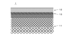
- FIG. 1 is a cross-sectional view of a separation membrane composite 1.
- FIG. 2 is a cross-sectional view showing an enlarged portion of the separation membrane composite 1.
- the separation membrane composite 1 includes a porous support 11 and a separation membrane 12 provided on the support 11.
- the separation membrane 12 is a MOF membrane made of a metal-organic framework (hereinafter referred to as "MOF")
- MOF metal-organic framework
- the MOF membrane is at least a membrane of MOF formed on the surface of the support 11, and does not include a membrane in which MOF particles are simply dispersed in an organic membrane.
- the separation membrane 12 is drawn with a thick line.
- the separation membrane 12 is drawn with parallel diagonal lines. Also, in FIG. 2, the thickness of the separation membrane 12 is drawn thicker than it actually is.
- the support 11 is a porous member that is permeable to gas and liquid.
- the support 11 is a monolithic support having a single continuous columnar body that is molded as an integral unit and has a number of through holes 111 that each extend in the longitudinal direction (i.e., the left-right direction in FIG. 1).
- the support 11 is approximately cylindrical.
- the cross section perpendicular to the longitudinal direction of each through hole 111 i.e., cell
- the diameter of the through holes 111 is drawn larger than the actual diameter, and the number of through holes 111 is drawn smaller than the actual number.
- the separation membrane 12 is formed on the inner circumferential surface of the through holes 111 and covers the inner circumferential surface of the through holes 111 over almost the entire surface.
- the length of the support 11 (i.e., the length in the left-right direction in FIG. 1) is, for example, 10 cm to 200 cm.
- the outer diameter of the support 11 is, for example, 0.5 cm to 30 cm.
- the distance between the central axes of adjacent through holes 111 is, for example, 0.3 mm to 10 mm.
- the surface roughness (Ra) of the support 11 is, for example, 0.1 ⁇ m to 5.0 ⁇ m, and preferably 0.2 ⁇ m to 2.0 ⁇ m.
- the shape of the support 11 may be, for example, a honeycomb shape, a flat plate shape, a tubular shape, a cylindrical shape, a columnar shape, or a polygonal column shape. When the shape of the support 11 is a tubular or cylindrical shape, the thickness of the support 11 is, for example, 0.1 mm to 10 mm.
- the support 11 is made of ceramic.
- ceramic sintered bodies selected as the material for the support 11 include alumina, silica, mullite, zirconia, titania, yttria, silicon nitride, silicon carbide, and the like.
- the support 11 contains at least one of alumina, silica, and mullite.
- the support 11 may contain an inorganic binder.
- the inorganic binder at least one of titania, mullite, sinterable alumina, silica, glass frit, clay minerals, and sinterable cordierite can be used.
- the average pore diameter of the support 11 is, for example, 0.01 ⁇ m to 70 ⁇ m, and preferably 0.05 ⁇ m to 25 ⁇ m.
- the average pore diameter of the support 11 near the surface where the separation membrane 12 is formed is 0.01 ⁇ m to 1 ⁇ m, and preferably 0.05 ⁇ m to 0.5 ⁇ m.
- the average pore diameter can be measured, for example, by a mercury porosimeter, a perm porometer, or a nanoperm porometer.
- D5 is, for example, 0.01 ⁇ m to 50 ⁇ m
- D50 is, for example, 0.05 ⁇ m to 70 ⁇ m
- D95 is, for example, 0.1 ⁇ m to 2000 ⁇ m.
- the porosity of the support 11 near the surface where the separation membrane 12 is formed is, for example, 20% to 60%.
- the support 11 has a multilayer structure in which, for example, multiple layers with different average pore diameters are stacked in the thickness direction.
- the average pore diameter and sintered grain size in the surface layer, including the surface on which the separation membrane 12 is formed, are smaller than the average pore diameter and sintered grain size in the layers other than the surface layer.
- the average pore diameter of the surface layer of the support 11 is, for example, 0.01 ⁇ m to 1 ⁇ m, and preferably 0.05 ⁇ m to 0.5 ⁇ m.
- the materials for each layer can be those described above.
- the materials of the multiple layers that form the multilayer structure may be the same or different. Note that when the support 11 has a multilayer structure, the average pore diameter of the support 11 refers to the average pore diameter of the surface layer, including the surface on which the separation membrane 12 is formed.
- Separation membrane 12 is a porous membrane having fine pores (micropores). Separation membrane 12 is capable of separating a specific substance from a mixture of multiple types of substances by utilizing molecular sieve action or the like. Other substances are less likely to permeate separation membrane 12 than the specific substance. In other words, the permeation rate of the other substances through separation membrane 12 is lower than the permeation rate of the specific substance.
- the average thickness of the separation membrane 12 is 2 ⁇ m or less. This allows a high permeation rate to be achieved.
- the lower limit of the average thickness of the separation membrane 12 is not particularly limited, but from the viewpoint of improving separation performance, it is, for example, 0.2 ⁇ m, preferably 0.5 ⁇ m, and more preferably 0.7 ⁇ m.
- a cross section perpendicular to the surface of the separation membrane 12 is exposed, for example, by cross-sectional polishing. In the cross section, randomly determined multiple fields (for example, seven fields) are observed by a scanning electron microscope (SEM). The magnification of the SEM is, for example, 5000 times.
- the average thickness of the separation membrane 12 in each field is obtained, and the arithmetic average of the field average thicknesses of the remaining fields excluding the fields with the maximum and minimum field average thickness values is obtained as the average thickness of the separation membrane 12.
- the surface roughness (Ra) of the separation membrane 12 is, for example, 2 ⁇ m or less, preferably 1 ⁇ m or less, and more preferably 0.5 ⁇ m or less.
- the separation membrane 12 is composed of MOFs. That is, the separation membrane 12 is an MOF membrane.
- the separation membrane 12 is typically composed only of MOFs, but depending on the manufacturing method, the separation membrane 12 may contain a small amount (e.g., 1 mass % or less) of substances other than MOFs.
- the pore diameter of the MOFs constituting the separation membrane 12 is, for example, 1 nm or less. The pore diameter can be calculated from the skeletal structure of the MOF crystal. The pore diameter is smaller than the average pore diameter of the support 11 near the surface on which the separation membrane 12 is formed.
- the average particle diameter of the MOF constituting the separation membrane 12 is, for example, 0.1 ⁇ m to 2 ⁇ m.
- the average particle diameter is preferably 1 ⁇ m or less, and more preferably 0.5 ⁇ m or less.
- the average particle diameter of the MOF in this embodiment is the arithmetic average of the maximum diameters of multiple particles (e.g., 30 particles) measured by cross-sectional observation using a SEM.
- the multiple particles to be measured may be randomly selected on the SEM image.
- a composite layer 13 is formed in which crystals of the MOF penetrate into the pores of the support 11.
- the composite layer 13 is shown by drawing parallel diagonal lines over a portion of the support 11.
- the composite layer 13 is part of the support 11.
- the thickness of the composite layer 13 is, for example, 2 ⁇ m or less. This makes it possible to suppress the decrease in permeation rate caused by the presence of the composite layer 13.
- the composite layer 13 does not have to be present, and the lower limit of the thickness of the composite layer 13 is 0.
- the boundary position of the composite layer 13 in the direction perpendicular to the interface between the support 11 and the separation membrane 12 is identified near one measurement position in the direction along the interface.
- the boundary position on the separation membrane 12 side of the composite layer 13 is the interface between the separation membrane 12 and the support 11.
- the boundary position on the opposite side of the separation membrane 12 in the composite layer 13 is the edge of the MOF that is farthest from the separation membrane 12 in the depth direction among the MOFs present in the pores of the support 11.
- the depth-wise distance between the boundary position on the separation membrane 12 side of the composite layer 13 and the boundary position on the opposite side of the separation membrane 12 is obtained as the thickness of the composite layer 13 at the measurement position. Then, the average of the thicknesses of the composite layer 13 at multiple different measurement positions (for example, 10 measurement positions) is determined as the thickness of the composite layer 13 in the separation membrane composite 1.
- the MOF constituting the separation membrane 12 is composed of aluminum ions (Al 3+ ) and ligands (organic ligands) coordinated to the aluminum ions.
- the ligands preferably have a high affinity for CO 2 , and include, for example, 1H-pyrrole-2,5-dicarboxylic acid, 2,5-furandicarboxylic acid, or 3,5-pyridinedicarboxylic acid. Other ligands may be used depending on the type of substance to be separated.
- the powder X-ray diffraction (XRD) pattern of the MOF of the separation membrane 12 has peaks at all diffraction angles 2 ⁇ listed in Table 2.
- the powder X-ray diffraction pattern is obtained using CuK ⁇ radiation as the radiation source of the X-ray diffraction device.
- an X-ray diffraction device manufactured by Rigaku (device name: MiniFlex600) is used, with a tube voltage of 40 kV, tube current of 15 mA, scanning speed of 0.5°/min, and scanning step of 0.02°.
- the divergence slit is 1.25°, scattering slit 1.25°, receiving slit 0.3 mm, incident Soller slit 5.0°, and receiving Soller slit 5.0°.
- No monochromator is used, and 0.015 mm thick nickel foil is used as the CuK ⁇ radiation filter.
- step S11 seed crystals to be used in manufacturing the separation membrane 12 are prepared (step S11).
- the seed crystals are obtained from MOF powder, which is produced, for example, by hydrothermal synthesis (solvothermal synthesis).
- the MOF powder may be produced by any manufacturing method or a known manufacturing method.
- the MOF powder may be used as the seed crystal as it is, or the seed crystals may be obtained by processing the powder by crushing or the like.
- the average particle size (D50) of the seed crystals is preferably 0.5 ⁇ m or less. This makes it possible to suppress the occurrence of grain boundary defects in the separation membrane 12, which would otherwise be caused by the average particle size of the MOF becoming excessively large.
- There is no particular lower limit to the average particle size of the seed crystals but for example, by setting the average particle size to 0.1 ⁇ m or more, it is possible to suppress a decrease in the crystallinity of the seed crystals.
- the average particle size of the seed crystals can be measured, for example, by a laser scattering method.
- the porous support 11 is immersed in the dispersion liquid in which the seed crystals are dispersed, and the seed crystals are attached to the support 11 (step S12).
- the dispersion liquid in which the seed crystals are dispersed is brought into contact with the portion of the support 11 where the separation membrane 12 is to be formed, thereby attaching the seed crystals to the support 11. In this way, a seed crystal-attached support is produced.
- the seed crystals may be attached to the support 11 by other methods.
- a synthesis solution (also called a synthesis sol or raw material solution) used to form the separation membrane 12 is prepared (step S13).
- the synthesis solution may be prepared before step S12 or in parallel with step S12.
- first, water, a monocarboxylate, a ligand, and an organic solvent are mixed.
- the monocarboxylate is, for example, a formate such as sodium formate, lithium formate, or potassium formate, or an acetate such as sodium acetate.
- the monocarboxylate acts as a modulator in the MOF synthesis and contributes to improving the crystallinity.
- an amino acid containing a monocarboxylate for example, glycine, arginine, etc.
- a monocarboxylate for example, glycine, arginine, etc.
- various organic compounds can be used as long as a powder X-ray diffraction pattern having a peak at the diffraction angle 2 ⁇ listed in Table 2 is obtained in the MOF synthesized using the ligand.
- a preferred ligand is an organic compound having a high affinity for CO2 , such as 1H-pyrrole-2,5-dicarboxylic acid, 2,5-furandicarboxylic acid, or 3,5-pyridinedicarboxylic acid.
- a preferred organic solvent is an organic compound having a carbonyl group (such as a carboxyl group), such as N,N-dimethylformamide (DMF), N-methyl-2-pyrrolidone (NMP), or N-methylformamide.
- a carbonyl group such as a carboxyl group
- DMF N,N-dimethylformamide
- NMP N-methyl-2-pyrrolidone
- N-methylformamide an organic solvent without a carbonyl group may also be used.
- the ratio of the amount of substance of the monocarboxylate to the amount of substance of the ligand (hereinafter also referred to as the "monocarboxylate/ligand ratio”) is preferably 0.5 to 1.8. If the monocarboxylate is not added, the synthesis solution becomes cloudy and loses uniformity even when the heating and stirring treatment described below is performed, making it difficult to produce an MOF. On the other hand, if an excessive amount of monocarboxylate is added, as described below, coordination defects in which some of the ligands constituting the MOF are missing are likely to occur.
- the ratio of the amount of substance of the organic solvent to the amount of substance of the ligand (hereinafter also referred to as the "organic solvent/ligand ratio") is preferably 0.1 to 10. If an organic solvent is not added, the crystallinity of the MOF decreases. On the other hand, if an excessive amount of organic solvent is added, as described below, coordination defects are likely to occur.
- a heating and stirring process (aging) is performed in which the solution is heated and stirred.
- the heating temperature in the heating and stirring process is, for example, 20 to 100°C, and preferably 40 to 80°C.
- the treatment time is, for example, 1 to 100 hours, and preferably 1 to 12 hours.
- Al source is, for example, aluminum sulfate, aluminum chloride, aluminum nitrate, aluminum hydroxide, boehmite, etc. In this way, a synthetic solution used to form the separation membrane 12 is obtained.
- the organic solvent does not necessarily need to be mixed into the solution before the heating and stirring process, and may be mixed during or after the heating and stirring process. In other words, the organic solvent may be mixed into the solution at any time.
- the support 11 with the seed crystals attached is immersed in the synthesis solution.
- the synthesis solution is then heated to start hydrothermal synthesis.
- the MOF grows using the seed crystals as nuclei, and a separation membrane 12, which is a dense MOF membrane, is formed on the support 11 (step S14).
- the synthesis temperature during hydrothermal synthesis is, for example, 40 to 200°C, preferably 70 to 150°C.
- the hydrothermal synthesis time is, for example, 1 to 100 hours, preferably 1 to 50 hours.
- the support 11 and separation membrane 12 are washed with pure water, and then washed with ethanol or the like. Preferably, washing with water and ethanol or the like is repeated multiple times. After washing, the support 11 and separation membrane 12 are dried, for example, at 100°C. Through the above processes, the above-mentioned separation membrane composite 1 is obtained.
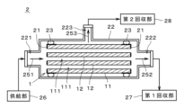
- Figure 4 is a diagram showing the separation device 2.
- Figure 5 is a diagram showing the flow of separation of a mixed substance by the separation device 2.
- a mixed substance containing multiple types of fluids i.e., gas or liquid
- highly permeable substances in the mixed substance are separated from the mixed substance by permeating the separation membrane composite 1. Separation in the separation device 2 may be performed, for example, for the purpose of extracting highly permeable substances from the mixed substance, or for the purpose of concentrating less permeable substances.
- the mixed substance (i.e., mixed fluid) may be a mixed gas containing multiple types of gas, a mixed liquid containing multiple types of liquid, or a gas-liquid two-phase fluid containing both gas and liquid.
- the mixture of substances may include, for example, one or more of the following substances: hydrogen ( H2 ), helium ( He ), nitrogen ( N2 ), oxygen (O2), water ( H2O ), carbon monoxide (CO), carbon dioxide ( CO2 ), nitrogen oxides, ammonia ( NH3 ), sulfur oxides, hydrogen sulfide ( H2S ), sulfur fluoride, mercury (Hg), arsine ( AsH3 ), hydrogen cyanide (HCN), carbonyl sulfide (COS), C1-C8 hydrocarbons, organic acids, alcohols, mercaptans, esters, ethers, ketones, and aldehydes.
- Nitrogen oxides are compounds of nitrogen and oxygen.
- gases called NOx (nox), such as nitric oxide ( NO ), nitrogen dioxide ( NO2 ) , nitrous oxide (also called dinitrogen oxide) ( N2O ), dinitrogen trioxide ( N2O3 ), dinitrogen tetroxide ( N2O4 ), and dinitrogen pentoxide ( N2O5 ) .
- Sulfur oxides are compounds of sulfur and oxygen.
- the above-mentioned sulfur oxides are, for example, gases called SOx , such as sulfur dioxide ( SO2 ) and sulfur trioxide ( SO3 ).
- Sulfur fluoride is a compound of fluorine and sulfur.
- C1-C8 hydrocarbons are those having at least one carbon and no more than eight carbons.
- C3-C8 hydrocarbons may be straight-chain compounds, branched-chain compounds, or cyclic compounds.
- C2-C8 hydrocarbons may be either saturated hydrocarbons (i.e., those having no double bonds or triple bonds in the molecule) or unsaturated hydrocarbons (i.e., those having double bonds and/or triple bonds in the molecule).
- C1-C4 hydrocarbons are, for example, methane (CH 4 ), ethane (C 2 H 6 ), ethylene (C 2 H 4 ), propane (C 3 H 8 ), propylene (C 3 H 6 ), normal butane (CH 3 (CH 2 ) 2 CH 3 ), isobutane (CH(CH 3 ) 3 ), 1-butene (CH 2 ⁇ CHCH 2 CH 3 ), 2-butene (CH 3 CH ⁇ CHCH 3 ) or isobutene (CH 2 ⁇ C(CH 3 ) 2 ).
- the organic acid may be a carboxylic acid or a sulfonic acid.
- the carboxylic acid may be, for example, formic acid (CH 2 O 2 ), acetic acid (C 2 H 4 O 2 ), oxalic acid (C 2 H 2 O 4 ), acrylic acid (C 3 H 4 O 2 ), or benzoic acid (C 6 H 5 COOH).
- the sulfonic acid may be, for example, ethanesulfonic acid (C 2 H 6 O 3 S).
- the organic acid may be a chain compound or a cyclic compound.
- the above-mentioned alcohols are, for example, methanol (CH 3 OH), ethanol (C 2 H 5 OH), isopropanol (2-propanol) (CH 3 CH(OH)CH 3 ), ethylene glycol (CH 2 (OH)CH 2 (OH)) or butanol (C 4 H 9 OH).
- Mercaptans are organic compounds that have hydrogenated sulfur (SH) at the end, and are also called thiols or thioalcohols.
- Examples of the mercaptans include methyl mercaptan (CH 3 SH), ethyl mercaptan (C 2 H 5 SH), and 1-propanethiol (C 3 H 7 SH).
- esters are, for example, formates or acetates.
- ethers are, for example, dimethyl ether ((CH 3 ) 2 O), methyl ethyl ether (C 2 H 5 OCH 3 ) or diethyl ether ((C 2 H 5 ) 2 O).
- ketones are, for example, acetone ((CH 3 ) 2 CO), methyl ethyl ketone (C 2 H 5 COCH 3 ) or diethyl ketone ((C 2 H 5 ) 2 CO).
- aldehydes are, for example, acetaldehyde (CH 3 CHO), propionaldehyde (C 2 H 5 CHO) or butanal (butyraldehyde) (C 3 H 7 CHO).
- the mixed substance separated by the separation device 2 is described as a mixed gas containing multiple types of gas.
- the separation device 2 includes a separation membrane complex 1, a sealing section 21, a housing 22, two sealing members 23, a supply section 26, a first recovery section 27, and a second recovery section 28.
- the separation membrane complex 1, the sealing section 21, and the sealing members 23 are housed within the housing 22.
- the supply section 26, the first recovery section 27, and the second recovery section 28 are disposed outside the housing 22 and connected to the housing 22.
- the sealing portion 21 is a member attached to both ends of the support 11 in the longitudinal direction (i.e., the left-right direction in FIG. 4) and covers and seals both longitudinal end faces and the outer peripheral surfaces near both end faces of the support 11.
- the sealing portion 21 prevents gas from flowing in and out from both end faces of the support 11.
- the sealing portion 21 is, for example, a plate-like member made of glass or resin. The material and shape of the sealing portion 21 may be changed as appropriate. Note that the sealing portion 21 has a plurality of openings that overlap with the plurality of through holes 111 of the support 11, and therefore both longitudinal ends of each through hole 111 of the support 11 are not covered by the sealing portion 21. Therefore, gas and the like can flow in and out of the through holes 111 from both ends.
- the shape of the housing 22 is not limited, but for example, it is a substantially cylindrical tubular member.
- the housing 22 is formed of, for example, stainless steel or carbon steel.
- the longitudinal direction of the housing 22 is substantially parallel to the longitudinal direction of the separation membrane composite 1.
- a supply port 221 is provided at one end of the longitudinal direction of the housing 22 (i.e., the left end in FIG. 4), and a first discharge port 222 is provided at the other end.
- a second discharge port 223 is provided on the side of the housing 22.
- a supply section 26 is connected to the supply port 221.
- a first collection section 27 is connected to the first discharge port 222.
- a second collection section 28 is connected to the second discharge port 223.
- the internal space of the housing 22 is a sealed space isolated from the space surrounding the housing 22.
- the two seal members 23 are disposed around the entire circumference between the outer circumferential surface of the separation membrane complex 1 and the inner circumferential surface of the housing 22 near both longitudinal ends of the separation membrane complex 1.
- Each seal member 23 is an approximately annular member made of a material that is gas impermeable.
- the seal member 23 is, for example, an O-ring made of a flexible resin.
- the seal member 23 adheres to the outer circumferential surface of the separation membrane complex 1 and the inner circumferential surface of the housing 22 around the entire circumference. In the example shown in FIG. 4, the seal member 23 adheres to the outer circumferential surface of the sealing portion 21 and indirectly adheres to the outer circumferential surface of the separation membrane complex 1 via the sealing portion 21.
- the seal member 23 and the outer circumferential surface of the separation membrane complex 1, and the seal member 23 and the inner circumferential surface of the housing 22 are sealed, and gas is hardly or completely unable to pass through.
- the supply unit 26 supplies the mixed gas to the internal space of the housing 22 via the supply port 221.
- the supply unit 26 is, for example, a blower or a pump that pressurizes the mixed gas toward the housing 22.
- the blower or pump has a pressure adjustment unit that adjusts the pressure of the mixed gas supplied to the housing 22.
- the first recovery unit 27 and the second recovery unit 28 are, for example, a storage container that stores the gas derived from the housing 22, or a blower or a pump that transports the gas.
- the separation device 2 described above is prepared, and thus the separation membrane composite 1 is prepared (step S21).
- the supply unit 26 supplies a mixed gas containing a plurality of types of gases having different permeabilities to the separation membrane 12 to the internal space of the housing 22.
- the main components of the mixed gas are CO 2 and N 2.
- the mixed gas may contain gases other than CO 2 and N 2.
- the pressure of the mixed gas supplied from the supply unit 26 to the internal space of the housing 22 i.e., the introduction pressure
- the temperature at which the mixed gas is separated is, for example, 10°C to 150°C.
- the mixed gas supplied from the supply unit 26 to the housing 22 is introduced into each through hole 111 of the support 11 from the left end of the separation membrane composite 1 in the figure, as shown by the arrow 251.
- a gas with high permeability in the mixed gas e.g., CO 2 , hereinafter referred to as a "highly permeable substance”
- CO 2 a gas with high permeability in the mixed gas
- the highly permeable substance is separated from a gas with low permeability in the mixed gas (e.g., N 2 , hereinafter referred to as a "lowly permeable substance”) (step S22).
- the gas discharged from the outer circumferential surface of the support 11 (hereinafter referred to as a "permeating substance") is collected by the second collection unit 28 through the second discharge port 223, as shown by the arrow 253.
- the pressure (i.e., permeation pressure) of the gas recovered by the second recovery section 28 via the second discharge port 223 is, for example, about 1 atmosphere (0.101 MPa).
- non-permeable substances gas other than the gas that has permeated the separation membrane 12 and the support 11
- the pressure of the gas recovered by the first recovery section 27 via the first exhaust port 222 is, for example, approximately the same as the introduction pressure.
- the non-permeable substances may also include highly permeable substances that did not permeate the separation membrane 12.
- Table 3 shows the type of ligand, the D50 value (average particle size) of the seed crystals, the ratio of monocarboxylate salt/ligand, the ratio of organic solvent/ligand, and the conditions of the heating and stirring treatment in Examples 1 to 21 and Comparative Examples 1 to 7.
- a mixed solution was prepared by mixing 1.551 g of 1H-pyrrole-2,5-dicarboxylic acid and 1.36 g of sodium formate in 50 mL of deionized water. The mixed solution was stirred at 50°C for 3 hours, cooled to room temperature, and 3.333 g of aluminum sulfate 18-hydrate was added. Next, this solution was kept at 120°C for 12 hours. The precipitate was separated by a centrifuge and washed three times with deionized water and ethanol. As a result, a powder of MOF containing 1H-pyrrole-2,5-dicarboxylic acid as a ligand was obtained as seed crystals.
- a mixed solution was prepared by mixing 1.562 g of 2,5-furandicarboxylic acid and 1.36 g of sodium formate in 50 mL of deionized water. The mixed solution was stirred at 50°C for 3 hours, cooled to room temperature, and 2.413 g of aluminum chloride hexahydrate was added. Next, this solution was kept at 100°C for 12 hours. The precipitate was separated by a centrifuge and washed three times with deionized water and ethanol. As a result, a powder of MOF containing 2,5-furandicarboxylic acid as a ligand was obtained as seed crystals.
- a mixed solution was prepared by mixing 1.67 g of 3,5-pyridinedicarboxylic acid and 1.36 g of sodium formate in 50 mL of deionized water. The mixed solution was stirred at 50°C for 3 hours, cooled to room temperature, and 3.333 g of aluminum sulfate 18-hydrate was added. Next, this solution was kept at 120°C for 12 hours. The precipitate was separated by a centrifuge and washed three times with deionized water and ethanol. As a result, a powder of MOF containing 3,5-pyridinedicarboxylic acid as a ligand was obtained as seed crystals.
- D50 average particle size
- Example 1 1.551 g of 1H-pyrrole-2,5-dicarboxylic acid, 1.22 g of sodium formate, and 0.58 g of N,N-dimethylformamide as an organic solvent were added to 150 mL of deionized water to prepare a mixed solution.
- the mixed solution was heated to 60° C. and stirred for 2 hours (heating and stirring treatment). After confirming that the mixed solution became transparent, it was cooled to room temperature. Then, 3.333 g of aluminum sulfate 18-hydrate was added to the mixed solution to prepare a synthesis solution.
- the monocarboxylate/ligand ratio (molar ratio; the same applies below) in the synthesis solution was 1.8, and the organic solvent/ligand ratio (molar ratio; the same applies below) was 0.8.
- a ceramic support carrying seed crystals (average particle size 0.33 ⁇ m) containing 1H-pyrrole-2,5-dicarboxylic acid and the synthesis solution were placed in a Teflon (registered trademark) container, and hydrothermal synthesis was performed at 100° C. for 20 hours.
- the obtained separation membrane composite was washed three times with deionized water and ethanol, and then dried.
- Example 2 The same procedure as in Example 1 was repeated except that the temperature of the hydrothermal synthesis was changed to 80°C.
- Example 3 The same procedure as in Example 1 was repeated except that the monocarboxylate/ligand ratio was changed to 1.
- Example 4 The same procedure was followed as in Example 1, except that the monocarboxylate/ligand ratio was changed to 0.6.
- Example 5 The procedure was the same as in Example 1, except that the heating temperature in the heating and stirring treatment of the mixed solution was changed to 40° C. and the stirring time was changed to 5 hours.
- Example 6 The same procedure as in Example 1 was repeated except that the heating temperature in the heating and stirring treatment of the mixed solution was changed to 80° C. and the stirring time was changed to 12 hours.
- Example 7 The procedure was the same as in Example 1, except that the organic solvent/ligand ratio was changed to 0.1.
- Example 8 The same procedure as in Example 1 was repeated except that the organic solvent/ligand ratio was changed to 8.
- Example 9 The procedure was the same as in Example 1, except that the hydrothermal synthesis time was 10 hours and the organic solvent was changed to N-methylformamide.
- Example 10 The procedure was the same as in Example 1, except that the average particle size of the seed crystals supported on the ceramic support was changed to 0.50 ⁇ m.
- Example 11 1.562 g of 2,5-furandicarboxylic acid, 1.22 g of sodium formate, and 0.58 g of N,N-dimethylformamide as an organic solvent were added to 150 mL of deionized water to prepare a mixed solution.
- the mixed solution was heated to 60°C and stirred for 2 hours (heating and stirring treatment). After confirming that the mixed solution became transparent, it was cooled to room temperature. Then, 2.413 g of aluminum chloride hexahydrate was added to the mixed solution to prepare a synthesis solution.
- the ratio of monocarboxylate/ligand in the synthesis solution was 1.8, and the ratio of organic solvent/ligand in the synthesis solution was 0.8.
- a ceramic support carrying seed crystals (average particle size 0.25 ⁇ m) containing 2,5-furandicarboxylic acid and the synthesis solution were placed in a Teflon container, and hydrothermal synthesis was performed at 80°C for 20 hours.
- the obtained separation membrane composite was washed three times with deionized water and ethanol, and then dried.
- Example 12 The same procedure as in Example 11 was repeated except that the heating temperature in the heating and stirring treatment of the mixed solution was changed to 40°C.
- Example 13 The same procedure was followed as in Example 11, except that the monocarboxylate/ligand ratio was changed to 1.
- Example 14 The same procedure as in Example 11 was repeated except that the organic solvent/ligand ratio was changed to 2.
- Example 15 1.67 g of 3,5-pyridinedicarboxylic acid, 1.22 g of sodium formate, and 0.58 g of N,N-dimethylformamide as an organic solvent were added to 150 mL of deionized water to prepare a mixed solution.
- the mixed solution was heated to 60°C and stirred for 2 hours (heating and stirring treatment). After confirming that the mixed solution became transparent, it was cooled to room temperature. Then, 3.333 g of aluminum sulfate 18-hydrate was added to the mixed solution to prepare a synthesis solution.
- the ratio of monocarboxylate/ligand in the synthesis solution was 1.8, and the ratio of organic solvent/ligand in the synthesis solution was 0.8.
- a ceramic support carrying seed crystals (average particle size 0.35 ⁇ m) containing 3,5-pyridinedicarboxylic acid and the synthesis solution were placed in a Teflon container, and hydrothermal synthesis was performed at 100°C for 20 hours.
- the obtained separation membrane composite was washed three times with deionized water and ethanol, and then dried.
- Example 16 The procedure was the same as in Example 15, except that the heating temperature in the heating and stirring treatment of the mixed solution was changed to 40°C.
- Example 17 The same procedure was followed as in Example 15, except that the monocarboxylate/ligand ratio was changed to 1.
- Example 18 The same procedure was followed as in Example 15, except that the organic solvent/ligand ratio was changed to 2.
- Example 19 0.775 g of 1H-pyrrole-2,5-dicarboxylic acid, 0.781 g of 2,5-furandicarboxylic acid, 1.26 g of lithium formate monohydrate, and 0.36 g of N,N-dimethylformamide as an organic solvent were added to 150 mL of deionized water to prepare a mixed solution.
- the mixed solution was heated to 60° C. and stirred for 2 hours (heating and stirring treatment). After confirming that the mixed solution became transparent, it was cooled to room temperature. Then, 3.333 g of aluminum sulfate 18-hydrate was added to the mixed solution to prepare a synthesis solution.
- the ratio of monocarboxylate/ligand in the synthesis solution was 1.5, and the ratio of organic solvent/ligand in the synthesis solution was 0.5.
- a ceramic support carrying the same seed crystals (seed crystals containing 1H-pyrrole-2,5-dicarboxylic acid) as in Example 1 and the synthesis solution were placed in a Teflon container, and hydrothermal synthesis was performed at 100° C. for 10 hours.
- the obtained separation membrane composite was washed three times with deionized water and ethanol, and then dried.
- Example 20 0.775 g of 1H-pyrrole-2,5-dicarboxylic acid, 0.835 g of 3,5-pyridinedicarboxylic acid, 1.51 g of sodium acetate, and 0.36 g of N,N-dimethylformamide as an organic solvent were added to 150 mL of deionized water to prepare a mixed solution.
- the mixed solution was heated to 60°C and stirred for 2 hours (heating and stirring treatment). After confirming that the mixed solution became transparent, it was cooled to room temperature. Then, 3.333 g of aluminum sulfate 18-hydrate was added to the mixed solution to prepare a synthesis solution.
- the ratio of monocarboxylate/ligand in the synthesis solution was 1.5, and the ratio of organic solvent/ligand in the synthesis solution was 0.5.
- a ceramic support carrying the same seed crystals (seed crystals containing 1H-pyrrole-2,5-dicarboxylic acid) as in Example 1 and the synthesis solution were placed in a Teflon container, and hydrothermal synthesis was performed at 100°C for 20 hours.
- the obtained separation membrane composite was washed three times with deionized water and ethanol, and then dried.
- Example 21 0.781 g of 2,5-furandicarboxylic acid, 0.781 g of 3,5-pyridinedicarboxylic acid, 1.47 g of potassium formate, and 0.58 g of N,N-dimethylformamide as an organic solvent were added to 150 mL of deionized water to prepare a mixed solution.
- the mixed solution was heated to 60°C and stirred for 2 hours (heating and stirring treatment). After confirming that the mixed solution became transparent, it was cooled to room temperature. Then, 3.333 g of aluminum sulfate 18-hydrate was added to the mixed solution to prepare a synthesis solution.
- the ratio of monocarboxylate/ligand in the synthesis solution was 1.5, and the ratio of organic solvent/ligand in the synthesis solution was 0.8.
- a ceramic support carrying the same seed crystals (seed crystals containing 2,5-furandicarboxylic acid) as in Example 11 and the synthesis solution were placed in a Teflon container, and hydrothermal synthesis was performed at 100°C for 20 hours.
- the obtained separation membrane composite was washed three times with deionized water and ethanol, and then dried.
- Comparative Example 2 The procedure was the same as in Comparative Example 1, except that the monocarboxylate/ligand ratio was changed to 0 (i.e., no monocarboxylate was added). In Comparative Example 2, no separation membrane was formed on the support.
- Example 4 The same as Example 1 was carried out, except that the organic solvent/ligand ratio was changed to 0 (i.e., no organic solvent was added).
- Comparative Example 5 A synthesis solution was prepared using the method and composition described in "Multivariate Polycrystalline Metal-Organic Framework Membranes for CO 2 /CH 4 Separation" by Weidong Fan et al. (J. Am. Chem. Soc., 2021, Vol. 143, pp. 17716-17723) (above reference 1), and membrane formation was performed without using seed crystals as in reference 1. In Comparative Example 5, it was not possible to cover the entire surface of the support on which the membrane was to be formed with the separation membrane.
- Comparative Example 6 The same procedure was followed as in Comparative Example 5, except that the same seed crystals as in Example 11 (seed crystals containing 2,5-furandicarboxylic acid) were used.
- the average thickness of the separation membrane, the thickness of the composite layer, and the average particle size of the separation membrane were measured by cross-sectional observation using a SEM, as described above.
- the average thickness of the separation membrane was 2 ⁇ m or less, and the thickness of the composite layer was 2 ⁇ m or less.
- the thickness of the composite layer was 2 ⁇ m or less, but the average thickness of the separation membrane was 2 ⁇ m or more.
- no separation membrane was formed on the support.
- the average particle size of the separation membrane was less than 0.5 ⁇ m, but in Comparative Examples 1 and 5 to 7, the average particle size of the separation membrane was greater than 2 ⁇ m.
- the permeation rate of each of CO2 gas, SF6 gas, and He gas was measured using the above-mentioned separation device 2.
- the permeation rate was not measured.
- the CO2 permeation rate was 1000 GPU or more, and a high permeation rate was realized.
- the CO2 permeation rate was less than 1000 GPU. Note that 1 GPU is 1 ⁇ 10 ⁇ 6 cm 3 (STP)/(cm 2 ⁇ sec ⁇ cmHg).
- the ratio of the permeation rate of SF6 gas to the permeation rate of He gas was 0.020 or less.
- the permeation rate ratio of SF 6 /He was greater than 0.020.
- the grain boundary defects and coordination defects are expected to have a defect size of 0.5 nm or more, so in this embodiment, the amount of defects in the separation membrane was evaluated based on the permeation rate ratio between SF 6 gas , which has a kinetic molecular diameter of 0.56 nm, and He gas, which has a kinetic molecular diameter sufficiently smaller than that of SF 6 gas.
- the permeation rate ratio of SF 6 /He was 0.020 or less in all cases, and SF 6 gas hardly permeated. Therefore, it can be said that the separation membrane composites of Examples 1 to 21 have reduced grain boundary defects and coordination defects, and a high separation factor can be obtained.
- the permeation rate ratio of SF 6 /He was greater than 0.020, and a large amount of SF 6 gas permeated. Therefore, in the separation membrane composite of the comparative example, the separation factor is low due to the influence of the grain boundary defects and the coordination defects.
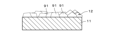
- Figures 6A and 6B are diagrams for explaining the synthesis of separation membrane 92 of a comparative example having a relatively large average particle size.
- Figures 7A and 7B are diagrams for explaining the synthesis of separation membrane 12 of Examples 1 to 21 having a relatively small average particle size.
- Figures 6A and 7A show the initial state of membrane synthesis, and Figures 6B and 7B show the state at the completion of membrane synthesis.
- the particle size of the MOF crystals 91 becomes large in the early stages of membrane synthesis. In this case, the gaps between the MOF crystals 91 also become large, making it easier for grain boundary defects to occur. In order to fill the gaps between the MOF crystals 91, it is necessary to grow the MOF crystals 91 large, as shown in Figure 6B, and the thickness of the separation membrane 92 becomes large. In other words, a separation membrane with an average thickness of about 2 ⁇ m has a low separation coefficient.
- the separation membrane 12 is synthesized by the secondary growth method using seed crystals with a small average particle size (for example, 0.5 ⁇ m or less), so the particle size of the MOF crystals 91 is small at the beginning of membrane synthesis, as shown in FIG. 7A. Therefore, the gaps between the MOF crystals 91 are also small, making it difficult for grain boundary defects to occur. Even at the completion of membrane synthesis, when the average membrane thickness is 2 ⁇ m or less, the average particle size of the separation membrane 12 (average particle size of the MOF crystals 91) remains small at 0.1 to 2 ⁇ m, as shown in FIG. 7B, and the occurrence of grain boundary defects is suppressed.
- a small average particle size for example, 0.5 ⁇ m or less
- the average particle size of the separation membrane becomes small is not necessarily clear, but in Comparative Examples 1, 6, and 7, in which the heating and stirring treatment was not performed, the average particle size was larger than 2 ⁇ m in all cases, so it is believed that the heating and stirring treatment contributed to this.
- the ligand used as the raw material of the synthesis solution is heated and dissolved, and it is believed that the precursor of the MOF in the synthesis solution is adsorbed to the seed crystals and stabilized, and this is presumed to affect the formation of the MOF membrane as described above.
- the average membrane thickness of the separation membrane can be made thin (2 ⁇ m or less) to easily achieve a high permeation rate.
- the thickness of the composite layer of the support and MOF is also 2 ⁇ m or less, and the permeation rate of CO 2 gas is 1000 GPU or more.
- the separation membrane composite 1 includes a porous support 11 formed of ceramic, and a separation membrane 12 formed on the support 11 and made of MOF.
- the average thickness of the separation membrane 12 is 2 ⁇ m or less.
- the MOF is made of aluminum ions and ligands coordinated to the aluminum ions.
- the powder X-ray diffraction pattern of the MOF has a peak at the diffraction angle 2 ⁇ shown in Table 2 above.
- the permeation rate ratio of SF 6 /He is 0.020 or less. In such a separation membrane composite 1, both a high separation factor and a high permeation rate can be achieved.
- the average particle size of the MOF is 0.1 ⁇ m to 2 ⁇ m. This reduces grain boundary defects in the thin separation membrane 12, improving the separation factor.
- the ligand of the MOF contains any one of 1H-pyrrole-2,5-dicarboxylic acid, 2,5-furandicarboxylic acid, and 3,5-pyridinedicarboxylic acid.
- the permeation rate of CO2 gas can be improved.
- the thickness of the composite layer 13 of the support 11 and MOF is 2 ⁇ m or less. This allows a higher permeation rate to be achieved in the separation membrane composite 1.
- the CO2 gas permeation rate is 1000 GPU or more. This allows the CO2 gas to be separated in a suitable manner. Depending on the application of the separation membrane composite 1, the CO2 gas permeation rate may be less than 1000 GPU.
- the method for producing the separation membrane composite 1 includes a step of attaching seed crystals made of MOFs onto a porous support 11 (step S12), a step of preparing a synthesis solution (step S13), and a step of immersing the support 11 in the synthesis solution and growing MOFs from the seed crystals by hydrothermal synthesis to form a separation membrane 12 on the support 11 (step S14).
- Step S13 includes a heating and stirring process in which a solution containing water, a monocarboxylate, and a ligand is heated and stirred.
- an Al source is mixed into the solution after the heating and stirring process, and an organic solvent is mixed into the solution at any timing.
- the permeation rate ratio of SF 6 /He is 0.020 or less. This makes it possible to provide a separation membrane composite 1 having a high separation coefficient and permeation rate.
- MOF synthesis requires the use of large amounts of organic solvents such as methanol, ethanol, and DMF, which places a high burden on the environment.
- organic solvents such as methanol, ethanol, and DMF
- the organic solvent is an organic compound having a carbonyl group
- the ratio of the substance amount of the organic solvent to the substance amount of the ligand is 0.1 to 10. This makes it possible to properly form the MOF membrane while reducing the amount of organic solvent used and lowering the environmental burden.
- the ratio of the amount of monocarboxylate to the amount of ligand is 0.5 to 1.8. This allows the MOF membrane to be properly formed, while reducing coordination defects and improving the separation factor.
- the average particle size of the MOF may be outside the range of 0.1 ⁇ m to 2 ⁇ m, and the thickness of the composite layer 13 of the support 11 and the MOF may be greater than 2 ⁇ m.
- the organic solvent/ligand ratio may be outside the range of 0.1 to 10
- the monocarboxylate/ligand ratio may be outside the range of 0.5 to 1.8.
- the ligand contained in the MOF of the seed crystal may be different from the two or more types of ligands.
- powders of multiple types of MOFs with different ligands may be mixed and used as seed crystals.
- the ligand contained in the MOF of the seed crystal may be the same as or different from the one type of ligand.
- the separation membrane composite 1 may further include a functional membrane or a protective membrane laminated on the separation membrane 12.
- a functional membrane or protective membrane may be an inorganic membrane such as a zeolite membrane, a silica membrane, or a carbon membrane, or an organic membrane such as a polyimide membrane or a silicone membrane.
- a substance that easily adsorbs specific molecules such as CO2 may be added to the functional membrane or protective membrane laminated on the separation membrane 12.
- the separation membrane composite 1 may be manufactured by a method other than the above manufacturing method.
- the separation device 2 and separation method may separate substances other than those exemplified in the above description from the mixed substance.
- the separation membrane composite of the present invention can be used in a variety of fields as a separation membrane or adsorption membrane for various substances.
Landscapes
- Chemical & Material Sciences (AREA)
- Chemical Kinetics & Catalysis (AREA)
- Inorganic Chemistry (AREA)
- Engineering & Computer Science (AREA)
- Manufacturing & Machinery (AREA)
- Analytical Chemistry (AREA)
- Organic Chemistry (AREA)
- Crystallography & Structural Chemistry (AREA)
- Life Sciences & Earth Sciences (AREA)
- Geology (AREA)
- Separation Using Semi-Permeable Membranes (AREA)
Priority Applications (4)
| Application Number | Priority Date | Filing Date | Title |
|---|---|---|---|
| JP2025506500A JPWO2024190041A1 (https=) | 2023-03-10 | 2023-12-26 | |
| DE112023005707.9T DE112023005707T5 (de) | 2023-03-10 | 2023-12-26 | Trennmembrankomplex und Verfahren zur Herstellung eines Trennmembrankomplexes |
| CN202380092079.2A CN120752084A (zh) | 2023-03-10 | 2023-12-26 | 分离膜复合体及分离膜复合体的制造方法 |
| US19/289,338 US20250360468A1 (en) | 2023-03-10 | 2025-08-04 | Separation membrane complex and method of producing separation membrane complex |
Applications Claiming Priority (2)
| Application Number | Priority Date | Filing Date | Title |
|---|---|---|---|
| JP2023037303 | 2023-03-10 | ||
| JP2023-037303 | 2023-03-10 |
Related Child Applications (1)
| Application Number | Title | Priority Date | Filing Date |
|---|---|---|---|
| US19/289,338 Continuation US20250360468A1 (en) | 2023-03-10 | 2025-08-04 | Separation membrane complex and method of producing separation membrane complex |
Publications (1)
| Publication Number | Publication Date |
|---|---|
| WO2024190041A1 true WO2024190041A1 (ja) | 2024-09-19 |
Family
ID=92754565
Family Applications (1)
| Application Number | Title | Priority Date | Filing Date |
|---|---|---|---|
| PCT/JP2023/046745 Ceased WO2024190041A1 (ja) | 2023-03-10 | 2023-12-26 | 分離膜複合体および分離膜複合体の製造方法 |
Country Status (5)
| Country | Link |
|---|---|
| US (1) | US20250360468A1 (https=) |
| JP (1) | JPWO2024190041A1 (https=) |
| CN (1) | CN120752084A (https=) |
| DE (1) | DE112023005707T5 (https=) |
| WO (1) | WO2024190041A1 (https=) |
Cited By (2)
| Publication number | Priority date | Publication date | Assignee | Title |
|---|---|---|---|---|
| CN119350645A (zh) * | 2024-10-23 | 2025-01-24 | 南京师范大学 | 一种微米级gm-1材料的制备方法与应用 |
| CN120189832A (zh) * | 2025-05-22 | 2025-06-24 | 浙江师范大学 | 分离膜及其制备方法和应用 |
Citations (8)
| Publication number | Priority date | Publication date | Assignee | Title |
|---|---|---|---|---|
| US6936306B1 (en) * | 1998-03-30 | 2005-08-30 | William Marsh Rice University | Chemical control over ceramic porosity using carboxylate-alumoxanes |
| JP2012509360A (ja) * | 2008-11-18 | 2012-04-19 | セントレ ナショナル デ ラ リシェルシェ サイエンティフィック(セ・エン・エル・エス) | 金属有機構造体型結晶性ポーラスアルミニウムカルボキシラートの水熱製造方法 |
| JP2013249279A (ja) * | 2012-05-31 | 2013-12-12 | Kuraray Co Ltd | 金属錯体、並びにそれからなる吸着材、吸蔵材及び分離材 |
| JP2016185534A (ja) * | 2015-03-27 | 2016-10-27 | 新日鐵住金株式会社 | ガス吸着材ならびにガス分離装置及びガス貯蔵装置 |
| WO2020184033A1 (ja) * | 2019-03-08 | 2020-09-17 | 日本碍子株式会社 | 結晶性物質および膜複合体 |
| JP2021533972A (ja) * | 2018-08-16 | 2021-12-09 | コモンウェルス サイエンティフィック アンド インダストリアル リサーチ オーガナイゼーション | 金属有機構造体ベースの水捕捉装置 |
| WO2022172893A1 (ja) * | 2021-02-10 | 2022-08-18 | 日本碍子株式会社 | ゼオライト膜複合体およびゼオライト膜複合体の製造方法 |
| WO2022190793A1 (ja) * | 2021-03-10 | 2022-09-15 | 日本碍子株式会社 | ゼオライト膜複合体、分離装置、膜反応装置およびゼオライト膜複合体の製造方法 |
-
2023
- 2023-12-26 WO PCT/JP2023/046745 patent/WO2024190041A1/ja not_active Ceased
- 2023-12-26 CN CN202380092079.2A patent/CN120752084A/zh active Pending
- 2023-12-26 DE DE112023005707.9T patent/DE112023005707T5/de active Pending
- 2023-12-26 JP JP2025506500A patent/JPWO2024190041A1/ja active Pending
-
2025
- 2025-08-04 US US19/289,338 patent/US20250360468A1/en active Pending
Patent Citations (8)
| Publication number | Priority date | Publication date | Assignee | Title |
|---|---|---|---|---|
| US6936306B1 (en) * | 1998-03-30 | 2005-08-30 | William Marsh Rice University | Chemical control over ceramic porosity using carboxylate-alumoxanes |
| JP2012509360A (ja) * | 2008-11-18 | 2012-04-19 | セントレ ナショナル デ ラ リシェルシェ サイエンティフィック(セ・エン・エル・エス) | 金属有機構造体型結晶性ポーラスアルミニウムカルボキシラートの水熱製造方法 |
| JP2013249279A (ja) * | 2012-05-31 | 2013-12-12 | Kuraray Co Ltd | 金属錯体、並びにそれからなる吸着材、吸蔵材及び分離材 |
| JP2016185534A (ja) * | 2015-03-27 | 2016-10-27 | 新日鐵住金株式会社 | ガス吸着材ならびにガス分離装置及びガス貯蔵装置 |
| JP2021533972A (ja) * | 2018-08-16 | 2021-12-09 | コモンウェルス サイエンティフィック アンド インダストリアル リサーチ オーガナイゼーション | 金属有機構造体ベースの水捕捉装置 |
| WO2020184033A1 (ja) * | 2019-03-08 | 2020-09-17 | 日本碍子株式会社 | 結晶性物質および膜複合体 |
| WO2022172893A1 (ja) * | 2021-02-10 | 2022-08-18 | 日本碍子株式会社 | ゼオライト膜複合体およびゼオライト膜複合体の製造方法 |
| WO2022190793A1 (ja) * | 2021-03-10 | 2022-09-15 | 日本碍子株式会社 | ゼオライト膜複合体、分離装置、膜反応装置およびゼオライト膜複合体の製造方法 |
Cited By (2)
| Publication number | Priority date | Publication date | Assignee | Title |
|---|---|---|---|---|
| CN119350645A (zh) * | 2024-10-23 | 2025-01-24 | 南京师范大学 | 一种微米级gm-1材料的制备方法与应用 |
| CN120189832A (zh) * | 2025-05-22 | 2025-06-24 | 浙江师范大学 | 分离膜及其制备方法和应用 |
Also Published As
| Publication number | Publication date |
|---|---|
| US20250360468A1 (en) | 2025-11-27 |
| DE112023005707T5 (de) | 2025-12-04 |
| CN120752084A (zh) | 2025-10-03 |
| JPWO2024190041A1 (https=) | 2024-09-19 |
Similar Documents
| Publication | Publication Date | Title |
|---|---|---|
| WO2024190041A1 (ja) | 分離膜複合体および分離膜複合体の製造方法 | |
| JP7052011B2 (ja) | セラミック支持体、ゼオライト膜複合体、ゼオライト膜複合体の製造方法および分離方法 | |
| JP6932841B2 (ja) | ゼオライト膜複合体、ゼオライト膜複合体の製造方法、および、分離方法 | |
| WO2025052716A1 (ja) | Mof膜複合体の製造方法およびmof膜複合体 | |
| JP2023153913A (ja) | 支持体、ゼオライト膜複合体、ゼオライト膜複合体の製造方法、および、分離方法 | |
| JP7313544B2 (ja) | ガス分離方法およびゼオライト膜 | |
| US20210370236A1 (en) | Method of producing zeolite membrane complex and zeolite membrane complex | |
| JP7230176B2 (ja) | ゼオライト膜複合体、ゼオライト膜複合体の製造方法、および、分離方法 | |
| JP7538325B2 (ja) | ゼオライト膜複合体、分離装置、膜反応装置およびゼオライト膜複合体の製造方法 | |
| US20250303367A1 (en) | Separation membrane complex and method of producing separation membrane complex | |
| JP7170825B2 (ja) | 分離方法 | |
| JP7741293B2 (ja) | ゼオライト膜複合体および分離方法 | |
| JP7629676B2 (ja) | ゼオライト膜複合体およびゼオライト膜複合体の製造方法 | |
| JP7757416B2 (ja) | ゼオライト膜複合体、膜反応装置およびゼオライト膜複合体の製造方法 | |
| JP7757417B2 (ja) | ゼオライト膜複合体および膜反応装置 | |
| JP7657517B2 (ja) | 分離膜複合体および分離膜複合体の製造方法 | |
| JP7297475B2 (ja) | ゼオライト合成用ゾル、ゼオライト膜の製造方法、および、ゼオライト粉末の製造方法 | |
| WO2025197219A1 (ja) | Mof膜複合体およびmof膜複合体の製造方法 | |
| WO2025177630A1 (ja) | 分離膜複合体および分離膜複合体の製造方法 | |
| WO2025037457A1 (ja) | 分離膜複合体および分離膜複合体の製造方法 | |
| JP7836381B2 (ja) | ゼオライト膜複合体、ゼオライト膜複合体の製造方法および分離方法 | |
| WO2025182507A1 (ja) | 分離膜複合体および分離膜複合体の製造方法 | |
| WO2020184033A1 (ja) | 結晶性物質および膜複合体 | |
| WO2025163983A1 (ja) | 分離膜複合体および分離膜複合体の製造方法 |
Legal Events
| Date | Code | Title | Description |
|---|---|---|---|
| 121 | Ep: the epo has been informed by wipo that ep was designated in this application |
Ref document number: 23927643 Country of ref document: EP Kind code of ref document: A1 |
|
| WWE | Wipo information: entry into national phase |
Ref document number: 202380092079.2 Country of ref document: CN |
|
| ENP | Entry into the national phase |
Ref document number: 2025506500 Country of ref document: JP Kind code of ref document: A |
|
| WWE | Wipo information: entry into national phase |
Ref document number: 2025506500 Country of ref document: JP |
|
| WWE | Wipo information: entry into national phase |
Ref document number: 112023005707 Country of ref document: DE |
|
| WWP | Wipo information: published in national office |
Ref document number: 202380092079.2 Country of ref document: CN |
|
| WWP | Wipo information: published in national office |
Ref document number: 112023005707 Country of ref document: DE |
|
| 122 | Ep: pct application non-entry in european phase |
Ref document number: 23927643 Country of ref document: EP Kind code of ref document: A1 |