WO2024189948A1 - 電縫鋼管の製造方法及び電縫鋼管 - Google Patents
電縫鋼管の製造方法及び電縫鋼管 Download PDFInfo
- Publication number
- WO2024189948A1 WO2024189948A1 PCT/JP2023/036365 JP2023036365W WO2024189948A1 WO 2024189948 A1 WO2024189948 A1 WO 2024189948A1 JP 2023036365 W JP2023036365 W JP 2023036365W WO 2024189948 A1 WO2024189948 A1 WO 2024189948A1
- Authority
- WO
- WIPO (PCT)
- Prior art keywords
- face
- steel sheet
- plated steel
- welded
- pipe
- Prior art date
- Legal status (The legal status is an assumption and is not a legal conclusion. Google has not performed a legal analysis and makes no representation as to the accuracy of the status listed.)
- Ceased
Links
Images





Classifications
-
- B—PERFORMING OPERATIONS; TRANSPORTING
- B21—MECHANICAL METAL-WORKING WITHOUT ESSENTIALLY REMOVING MATERIAL; PUNCHING METAL
- B21C—MANUFACTURE OF METAL SHEETS, WIRE, RODS, TUBES, PROFILES OR LIKE SEMI-MANUFACTURED PRODUCTS OTHERWISE THAN BY ROLLING; AUXILIARY OPERATIONS USED IN CONNECTION WITH METAL-WORKING WITHOUT ESSENTIALLY REMOVING MATERIAL
- B21C37/00—Manufacture of metal sheets, rods, wire, tubes, profiles or like semi-manufactured products, not otherwise provided for; Manufacture of tubes of special shape
- B21C37/06—Manufacture of metal sheets, rods, wire, tubes, profiles or like semi-manufactured products, not otherwise provided for; Manufacture of tubes of special shape of tubes or metal hoses; Combined procedures for making tubes, e.g. for making multi-wall tubes
- B21C37/08—Making tubes with welded or soldered seams
- B21C37/0826—Preparing the edges of the metal sheet with the aim of having some effect on the weld
-
- B—PERFORMING OPERATIONS; TRANSPORTING
- B21—MECHANICAL METAL-WORKING WITHOUT ESSENTIALLY REMOVING MATERIAL; PUNCHING METAL
- B21C—MANUFACTURE OF METAL SHEETS, WIRE, RODS, TUBES, PROFILES OR LIKE SEMI-MANUFACTURED PRODUCTS OTHERWISE THAN BY ROLLING; AUXILIARY OPERATIONS USED IN CONNECTION WITH METAL-WORKING WITHOUT ESSENTIALLY REMOVING MATERIAL
- B21C37/00—Manufacture of metal sheets, rods, wire, tubes, profiles or like semi-manufactured products, not otherwise provided for; Manufacture of tubes of special shape
- B21C37/06—Manufacture of metal sheets, rods, wire, tubes, profiles or like semi-manufactured products, not otherwise provided for; Manufacture of tubes of special shape of tubes or metal hoses; Combined procedures for making tubes, e.g. for making multi-wall tubes
- B21C37/08—Making tubes with welded or soldered seams
- B21C37/083—Supply, or operations combined with supply, of strip material
-
- B—PERFORMING OPERATIONS; TRANSPORTING
- B21—MECHANICAL METAL-WORKING WITHOUT ESSENTIALLY REMOVING MATERIAL; PUNCHING METAL
- B21D—WORKING OR PROCESSING OF SHEET METAL OR METAL TUBES, RODS OR PROFILES WITHOUT ESSENTIALLY REMOVING MATERIAL; PUNCHING METAL
- B21D5/00—Bending sheet metal along straight lines, e.g. to form simple curves
- B21D5/06—Bending sheet metal along straight lines, e.g. to form simple curves by drawing procedure making use of dies or forming-rollers, e.g. making profiles
- B21D5/10—Bending sheet metal along straight lines, e.g. to form simple curves by drawing procedure making use of dies or forming-rollers, e.g. making profiles for making tubes
- B21D5/12—Bending sheet metal along straight lines, e.g. to form simple curves by drawing procedure making use of dies or forming-rollers, e.g. making profiles for making tubes making use of forming-rollers
-
- B—PERFORMING OPERATIONS; TRANSPORTING
- B23—MACHINE TOOLS; METAL-WORKING NOT OTHERWISE PROVIDED FOR
- B23K—SOLDERING OR UNSOLDERING; WELDING; CLADDING OR PLATING BY SOLDERING OR WELDING; CUTTING BY APPLYING HEAT LOCALLY, e.g. FLAME CUTTING; WORKING BY LASER BEAM
- B23K13/00—Welding by high-frequency current heating
-
- B—PERFORMING OPERATIONS; TRANSPORTING
- B23—MACHINE TOOLS; METAL-WORKING NOT OTHERWISE PROVIDED FOR
- B23K—SOLDERING OR UNSOLDERING; WELDING; CLADDING OR PLATING BY SOLDERING OR WELDING; CUTTING BY APPLYING HEAT LOCALLY, e.g. FLAME CUTTING; WORKING BY LASER BEAM
- B23K13/00—Welding by high-frequency current heating
- B23K13/01—Welding by high-frequency current heating by induction heating
- B23K13/02—Seam welding
- B23K13/025—Seam welding for tubes
-
- C—CHEMISTRY; METALLURGY
- C23—COATING METALLIC MATERIAL; COATING MATERIAL WITH METALLIC MATERIAL; CHEMICAL SURFACE TREATMENT; DIFFUSION TREATMENT OF METALLIC MATERIAL; COATING BY VACUUM EVAPORATION, BY SPUTTERING, BY ION IMPLANTATION OR BY CHEMICAL VAPOUR DEPOSITION, IN GENERAL; INHIBITING CORROSION OF METALLIC MATERIAL OR INCRUSTATION IN GENERAL
- C23C—COATING METALLIC MATERIAL; COATING MATERIAL WITH METALLIC MATERIAL; SURFACE TREATMENT OF METALLIC MATERIAL BY DIFFUSION INTO THE SURFACE, BY CHEMICAL CONVERSION OR SUBSTITUTION; COATING BY VACUUM EVAPORATION, BY SPUTTERING, BY ION IMPLANTATION OR BY CHEMICAL VAPOUR DEPOSITION, IN GENERAL
- C23C4/00—Coating by spraying the coating material in the molten state, e.g. by flame, plasma or electric discharge
- C23C4/02—Pretreatment of the material to be coated, e.g. for coating on selected surface areas
Definitions
- the present invention relates to a method for manufacturing electric-resistance welded steel pipes and electric-resistance welded steel pipes.
- Plated steel sheets exhibit high corrosion resistance on the surface where the plating is coated, due to the anticorrosive properties of the plating.
- the temperatures near the weld become high locally, causing the plating components to evaporate and reducing corrosion resistance.
- some of the plating in the vicinity is also removed along with the bead, leaving the iron base exposed around the weld, which can further expand the area where corrosion resistance is reduced.
- the decrease in corrosion resistance around the welds is generally compensated for by carrying out post-repair such as spraying the main plating component (e.g. Zn) around the welds.
- the corrosion resistance around the repaired welds is not necessarily restored to the same level as other areas. Due to this decrease in corrosion resistance around the welds, in fields where high corrosion resistance is required, post-plated products that are immersed in hot-dip galvanizing after processing are used, rather than pre-plated products manufactured by processing galvanized steel sheets. Given this situation, there is a demand to improve the corrosion resistance around the welds of electric resistance welded steel pipes using galvanized steel sheets as the base material, in order to increase productivity.
- Patent Document 1 discloses a technique for manufacturing electric resistance welded steel pipes in the past, in which the ends of a strip are given a tapered shape with inclined surfaces that connect from the vertical end face of the strip to both end faces on the outer diameter side and the inner diameter side in the thickness direction of the strip, and then electric resistance welding is performed with the butt angle of the vertical end faces of the strip being within a range of ⁇ 1 degree.
- Patent Document 2 discloses a technique for forming a steel strip into a roughly tubular shape, giving a taper to both the outer and inner surfaces of both edges of an open tube, with the angle between the inclined surface and the vertical end face of the steel strip being 15 to 50 degrees, and the length of the inclined surface in the thickness direction from the steel strip surface being 10 to 45% of the steel strip thickness, and then electric resistance welding is performed with an upset amount of 40 to 75% of the steel strip thickness.
- Patent Document 3 discloses a method of butt welding after grinding off the plated layer at both widthwise ends that will become the welds. By removing the plated layer, which has a negative effect on the welding conditions and the structure of the weld, it is possible to obtain a weld with properties almost identical to those of the base material.
- Patent Documents 1 and 2 are intended for electric resistance welded steel pipes used as oil well tubular goods or line pipes, which require stricter corrosion resistance, and do not envisage the manufacture of electric resistance welded steel pipes using galvanized steel sheets as the base sheet.
- the technology described in Patent Document 3 removes the galvanized layer at both ends in the width direction, which will become the welded parts, and so there are concerns that the corrosion resistance around the welded parts will decrease.
- the present invention has been made in consideration of the above problems, and the object of the present invention is to provide an electric resistance welded steel pipe manufacturing method and electric resistance welded steel pipe that can suppress the decrease in corrosion resistance around the welded parts in electric resistance welded steel pipes made from galvanized steel sheets.
- a method for manufacturing an electric resistance welded steel pipe comprising an end face forming process in which an outer inclined portion that inclines in the plate thickness direction from the outer surface side toward the inner surface side is formed on each of a first end face and a second end face on both sides of the width direction of a plated steel sheet, or an outer inclined portion and an inner inclined portion that inclines in the plate thickness direction from the inner surface side toward the outer surface side, so that the first end face and the second end face have a shape in which the plate thickness decreases from the center in the width direction toward the end face, and a pipe making process in which the formed first end face and the formed second end face are butt welded together to form a pipe.
- At least a portion of the outer inclined portion may be coated with a continuous plating from the outer surface side.
- the first end face and the second end face may be heated and melted, and the first end face and the second end face may be pressed together to join them so that the ratio of the width of the weld bead on the outer surface side to the thickness of the plated steel sheet is 92% or less.
- plating may be applied to the welded portion where the first end face and the second end face are pressed together and joined.
- the plated steel sheet may be wound into a coil, and in the pipe making process, the plated steel sheet wound into a coil in the end face forming process may be discharged to make a pipe.
- an electric resistance welded steel pipe using a plated steel sheet as a base sheet which has a welded portion extending in the axial direction and a heat-affected portion extending in the axial direction on both circumferential sides of the welded portion, the ratio of the outer surface circumferential length of the welded portion to the plated steel sheet thickness is 48% or more, and for each heat-affected portion, the ratio of the outer surface circumferential length of the heat-affected portion to the plated steel sheet thickness is 40% or less.
- an electric resistance welded steel pipe using a plated steel sheet as a base sheet the outer surface of which has a post-plated portion where plating is applied at least along a weld extending in the axial direction, and the ratio of the outer surface circumferential length of the post-plated portion to the sheet thickness of the plated steel sheet is 172% or less.
- the present invention makes it possible to suppress the deterioration of corrosion resistance around the welds in electric resistance welded steel pipes made from galvanized steel sheets.
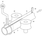
- FIG. 2 is an explanatory diagram showing an example of a welding step for welding both ends in the width direction of a cylindrically formed steel plate in the production of an electric resistance welded steel pipe.
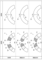
- 1 is a schematic diagram showing the shape of the welded portion of an electric resistance welded steel pipe using a plated steel sheet as a base sheet, viewed in the axial direction, before and after welding.
- FIG. 1 is an explanatory diagram showing an example of a technique for forming a first end face and a second end face of a plated steel sheet into a shape having an outer inclined portion and an inner inclined portion in an end face shaping process.
- FIG. 4 is a schematic side view of a cross section of a cut end surface of a plated steel sheet cut by the method of FIG. 3 .
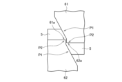
- FIG. 11 is an explanatory diagram showing an example of a technique for forming a first end face and a second end face of a plated steel sheet into a shape having an outer inclined portion in an end face shaping process.
- 6 is a schematic side view of a cross section of a cut end surface of a plated steel sheet cut by the method of FIG. 5 .
- FIG. 1 is an explanatory diagram showing a schematic view of the shape of the periphery of a welded portion of a plated steel sheet in a pipe-making process before and after welding as viewed in the axial direction.
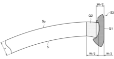
- FIG. FIG. 2 is an explanatory diagram showing the definitions of a weld width, a heat-affected zone width, and a bead width.
- 13 is a simulation result showing an example of the relationship between the pressing force and the bead width during welding for a steel pipe having an outer diameter of 114.3 mm.
- 13 is a simulation result showing an example of the relationship between the pressing force and the bead width during welding for a steel pipe having an outer diameter of 139.8 mm.
- 13 is a simulation result showing an example of the relationship between the pressing force and the bead width during welding for a steel pipe having an outer diameter of 159.8 mm.
- 11 is a simulation result showing a state when removal of the outer surface bead becomes unnecessary.
- molten steel is pushed out by pressure from the squeeze roll 20 to generate beads on the outer and inner surfaces of a welded portion 3c joining both ends 3a, 3b in the width direction.
- the beads generated on the outer surface are removed by, for example, a bite 30.
- the heat generated during welding causes localized high temperatures near both end faces of the plated steel sheet, causing the plating in those areas to evaporate.
- the amount of plating remaining around the welds is less than in other areas, or there is no plating remaining around the welds, resulting in reduced corrosion resistance only around the welds.
- the beads on the outer surface of the steel pipe are removed by cutting with a cutting tool or crushing with a roll.
- the plating in the vicinity of the beads is also partially removed, leaving the iron base metal exposed around the weld, which can expand the area of reduced corrosion resistance.
- the reduced corrosion resistance around the weld can be compensated for by carrying out post-repair work such as spraying the main plating component around the weld, but the corrosion resistance around the repaired weld is not necessarily restored to the same level as the rest of the area.
- the inventors of the present application considered that narrowing the bead removal width would reduce the area where the iron base metal is exposed around the welded part, and would suppress a decrease in corrosion resistance around the welded part. They then came up with the idea that by optimizing the shape of the end faces on both sides in the width direction of the plated steel sheet, the bead could be narrowed, and as a result, the bead removal width could be narrowed.
- the bead generated by welding the first end face and the second end face is narrowed.
- FIG. 2 is a schematic diagram showing the shape before and after welding in the axial direction of the welded portion of an electric resistance welded steel pipe using a plated steel sheet as the base sheet.
- the plated steel sheet 5 is formed into a cylindrical shape, and the first end face 51 and the second end face 52 on both sides in the width direction are heated.
- the heated parts of the plated steel sheet 5 are the welded portion Q1 and the heat-affected portion Q2 from the side close to the first end face 51 and the second end face 52.
- the circumferential width of the welded portion Q1 and the heat-affected portion Q2 is approximately the same as the plate thickness.
- the first end face 51 and the second end face 52 of the plated steel sheet 5 are butt-welded to each other, and an outer surface bead 53 is formed on the outer surface 5o side and an inner surface bead 54 is formed on the inner surface 5i side. Note that in FIG. 2, the shape around the welded portion is exaggerated to make the explanation easier to understand.
- the first end face 51 and the second end face 52 of the plated steel sheet 5 largely maintain the sheet shape before being formed into a cylindrical shape, and are substantially perpendicular to the outer surface 5o and the inner surface 5i.
- the base metal of the welded portion Q1 is pushed out toward the outer surface 5o and the inner surface 5i, forming an outer surface bead 53 and an inner surface bead 54.
- End face shape A and end face shape B in FIG. 2 are examples of the shapes of the first end face 51 and the second end face 52 according to one embodiment of the present invention.
- the end face shape A is a shape in which the corners on the outer surface 5o side and the inner surface 5i side are chamfered. As shown in FIG. 2, the end face shape A is composed of an outer inclined portion 5s that inclines in the plate thickness direction from the outer surface 5o side toward the inner surface 5i side, and an inner inclined portion 5t that inclines in the plate thickness direction from the inner surface 5i side toward the outer surface 5o side, and is a shape in which the plate thickness decreases toward the end face.
- the amount of base metal of the welded portion Q1 is less than that of the conventional example by the amount of the corners on the outer surface 5o side and the inner surface 5i side. Therefore, when the first end face 51 and the second end face 52 having the end face shape A are butted together and welded, both the outer surface bead 53 and the inner surface bead 54 are smaller than those of the comparative example.
- the end face shape B is a shape in which the corners on the outer surface 5o side are chamfered. As shown in FIG. 2, the end face shape B includes an outer inclined portion 5s that inclines in the plate thickness direction from the outer surface 5o side toward the inner surface 5i side, and the plate thickness decreases toward the end face. In the example of the end face shape B shown in FIG. 2, a surface 5r that is approximately perpendicular to the inner surface 5i exists on the inner surface 5i side, but the end face shape B may only have the outer inclined portion 5s.
- the amount of base metal of the welded portion Q1 is less by the amount of the corners on the outer surface 5o side compared to the conventional example. Therefore, when the first end face 51 and the second end face 52 having the end face shape B are butted together and welded, the outer surface bead 53 is smaller than that of the comparative example.
- the bead that is generated after welding can be narrowed, and as a result, the width of the bead that needs to be removed can be narrowed.
- This also narrows the repair width by spraying the main plating component, which compensates for the decrease in corrosion resistance, improving the corrosion resistance around the welded area.
- the inner bead 54 is expected to be approximately the same size as in the conventional example, but the inner bead 54 that cannot be seen from the outside may not be removed.
- the presence of an inner bead does not pose a problem.
- the present invention considers the presence or absence of an inner bead 54 to be irrelevant, and aims to narrow the outer bead 53.
- the method for producing an electric resistance welded steel pipe using a plated steel sheet according to one embodiment of the present invention as a base sheet includes an end face forming process for forming both end faces (first end face and second end face) in the width direction of the plated steel sheet as the base sheet, and a pipe making process for butt-welding the formed first end face and second end face together to form a pipe.
- the base plated steel sheet is assumed to be a plated steel sheet mainly composed of Zn.
- the first end face and the second end face of the plated steel sheet are formed into a shape in which the corners between the surface and the end face are chamfered only on the outer surface side, or on the outer surface side and the inner surface side.
- the first end face and the second end face are formed into a shape having an outer inclined portion 5s, or an outer inclined portion 5s and an inner inclined portion 5t, as in the end face shape A or the end face shape B shown in Fig. 2.
- the plated steel sheet is formed into a shape in which the sheet thickness decreases from the center in the width direction toward the end face (the first end face or the second end face).
- the outer inclined portion 5s and the inner inclined portion 5t may be flat as shown in Fig. 2, or may be curved.
- the method for forming the end face is not particularly limited, but it is desirable that the plating on the surface of the original plated steel sheet covers as much of the formed end face as possible. By covering the end face with plating, it is possible to minimize the repair width in which the main plating component is sprayed after welding the first end face and the second end face.
- a cutting device having a pair of annular blades 41, 42 with V-shaped blade edges 41a, 42a may be used as shown in Fig. 3 (for example, Patent Document 4).
- the tip angles ⁇ 1 , ⁇ 2 of the blade edges 41a, 42a of the cutting device are set to 10° to 120°, and the tip radii R 1 , R 2 of the blade edges 41a, 42a are set to 0.5% to 35.0% of the sheet thickness, and the plated steel sheet 5 is passed between the rotating annular blades 41, 42 to cut its end.
- the tensile force generated between the blade edges 41a, 42a of the pair of annular blades 41, 42 and the plated steel sheet 5 causes the plating on the surface of the plated steel sheet 5 to penetrate into the cut end face, and the cut end face is covered with the plating.
- FIG. 4 shows an example of a cut end surface of a plated steel sheet 5 cut by a cutting device having a pair of annular blades 41, 42 shown in FIG. 3.
- FIG. 4 is a schematic side view of a cross section of a cut end surface of a plated steel sheet 5 in which both surfaces of a base material 5a are covered with plating 5b.
- the cut end surface of the plated steel sheet 5 consists of a sag, an inclined surface, and a fractured surface.
- the sag and inclined surface on the upper side of FIG. 4 are formed by the cutting edge 41a of the annular blade 41 in FIG. 3, and the sag and inclined surface on the lower side of FIG.
- the inclined surface is covered by plating 5b that is continuous from the surface of the plated steel sheet 5.
- the fractured surface is caused by a crack generated in the plated steel sheet 5 by the cutting edges 41a, 42a, which is the starting point for fracture.
- the upper inclined surface in FIG. 4 becomes the outer inclined portion 5s after end face shaping
- the lower inclined surface in FIG. 4 becomes the inner inclined portion 5t after end face shaping.
- a cutting device having a pair of annular blades 41, 42 with V-shaped cutting edges 41a, 42a as shown in FIG. 3 it is possible to form the outer inclined portion 5s and the inner inclined portion 5t covered with plating 5b on the first end face and the second end face, respectively.
- a cutting device having a pair of slit blades 61, 62 with blade portions 61a, 62a having an inclined portion P1 and a protruding portion P2, as shown in FIG. 5, may be used.
- the inclined portion P1 of the blade portions 61a, 62a is inclined with respect to the pushing direction of the plated steel sheet 5, and the protruding portion P2 protrudes from the inclined portion P1 in the pushing direction.
- the plated steel sheet 5 is passed between the rotating slit blades 61, 62, and its end portion is cut.
- the inclined portion P1 of the blade portions 61a, 62a compresses the plating of the plating layer 5b, including the base material 5a, in the pushing direction (sheet thickness direction) and wraps around the cut end face, and the timing of cutting is delayed by applying a compressive stress, so that the inclined surface can be covered with plating.
- the plated steel sheet 5 is completely cut by the protrusions P2 of the blades 61a and 62a, which prevents the generation of large burrs.
- FIG. 6 shows an example of a cut end surface of a plated steel sheet 5 cut by a cutting device having a pair of slit blades 61, 62 shown in FIG. 5.
- FIG. 6 is a schematic diagram showing a cross section of a cut end surface of a plated steel sheet 5 in which both surfaces of a base material 5a are covered with plating 5b, viewed from the side. Note that FIG. 6 shows a cut end surface on the side where the surface (upper surface) opposite to the inclined portion P1 of the slit blade 61 in FIG. 5 is pressed in by the inclined portion P1 of the slit blade 61. As shown in FIG.
- the cut end surface of the plated steel sheet 5 has, in order from the upper surface, an inclined surface, a shear surface, and a fracture surface.
- the inclined surface is a surface formed along the inclined portion P1 of the blade portion 61a of the slit blade 61, and is inclined with respect to the sheet thickness direction.
- the shear surface is a smooth surface formed by the movement of the slit blade 61 that is embedded in the plated steel sheet 5, and occurs slightly.
- the fracture surface is a surface where the plated steel sheet 5 is broken, starting from a crack that has occurred in the plated steel sheet 5.
- the inclined surface in FIG. 6 becomes the outer inclined portion 5s after end face forming.
- a cutting device having a pair of slit blades 61, 62 shown in FIG. 5 it is possible to form the outer inclined portion 5s covered with plating 5b on each of the first end face and the second end face.
- the first end face 51 and the second end face 52 of the plated steel sheet 5 are each formed into a shape having an outer inclined portion 5s and an inner inclined portion 5t as shown in FIG. 4, or a shape having an outer inclined portion 5s as shown in FIG. 6.
- the outer inclined portion 5s and the inner inclined portion 5t do not necessarily have to be covered with plating, but it is preferable to cover at least a part of the outer inclined portion 5s with plating 5b that continues from the outer surface side.
- low-melting point components such as Zn in the plating 5b of the welded portion where the base material 5a is semi-molten evaporate, but the plating 5b remains in a molten state in the heat-affected zone, and solidifies after cooling to cover the base material 5a.
- the end face forming process by covering at least a part of the outer inclined portion 5s of the first end face 51 and the second end face 52 with plating 5b that continues from the outer surface side, the area where the base material 5a is exposed to the outside and the corrosion resistance is reduced can be reduced.
- the first end face 51 and the second end face 52 formed in the end face forming process are butted together and welded to form a pipe.
- the pipe forming process can be performed, for example, using the equipment shown in FIG. 1.
- the first end face 51 and the second end face 52 are heated and melted.
- the first end face 51 and the second end face 52 are pressed together to form a joint.
- the ratio of the width of the weld bead (outer surface bead 53) on the outer surface 5o side to the thickness of the plated steel sheet 5 (hereinafter, also referred to as "bead width") is set to 92% or less.
- the bead width is a portion that needs to be cut after welding, and is the circumferential width of the portion that is ejected from the outer surface 5o of the steel pipe to the outside.
- Figure 7 shows a schematic diagram of the shape of the periphery of the welded portion of the plated steel sheet 5 in the pipe-making process before and after welding, as viewed in the axial direction.
- Figure 7 shows a case in which the first end face 51 and the second end face 52 have the end face shape A shown in Figure 2.
- the heated portions of the plated steel sheet 5 are, from the side closest to the first end face 51 and the second end face 52, a welded portion Q1 and a heat-affected portion Q2.
- the welded portion Q1 is a portion where the base material iron is softened and semi-molten. In the welded portion Q1, the base material reaches a high temperature of 900°C or more, so that low-melting-point components such as Zn among the plating components that covered the surface of the plated steel sheet 5 evaporate.
- the heat-affected portion Q2 is a portion where the base material iron reaches a high temperature and the plating that covered the surface of the plated steel sheet 5 melts.
- the base material is at 400°C to 900°C, and in part or all of the region, some or all of the plating components are melted.
- the portion farther from the end (first end face 51 or second end face 52) than the heat-affected zone Q2 maintains the original plated steel sheet 5, and the outer surface 5o and inner surface 5i are coated with plating.
- the weld Q1 of the first end face 51 and the weld Q1 of the second end face 52 are pressed together to join the first end face 51 and the second end face 52.
- the triangular first end face 51 and the second end face 52 which are made up of an outer inclined portion 5s and an inner inclined portion 5t when viewed from the side, are deformed and disappear, and the plated steel sheet 5 becomes tubular (after welding 1).
- molten base metal is discharged from the outer surface 5o and the inner surface 5i, and becomes the outer bead 53 and the inner bead 54.
- the outer bead 53 visible from the outside is removed.
- the bead created after welding is narrowed, and the width of the bead to be removed is narrowed, thereby narrowing the repair width where the main plating component is sprayed, and improving the corrosion resistance around the welded portion.
- the ratio of the bead width of the outer bead 53 to the plate thickness of the plated steel sheet 5 is set to 92% or less.
- the width W1 of the weld Q1 (weld width), the width W2 of the heat-affected zone Q2 (heat-affected zone width), and the bead width Wb of the outer bead 53 are defined as shown in FIG. 8.
- the weld width W1 is the circumferential length of the weld Q1 on the outer surface 5o.
- the heat-affected zone width W2 is the circumferential length of the heat-affected zone Q2 on the outer surface 5o.
- the bead width Wb of the outer bead 53 is the circumferential length of the outer bead 53 on the outer surface 5o.
- FIG. 8 shows the periphery of the weld on one end face side. In other words, the weld width W1, heat-affected zone width W2, and bead width Wb of the entire steel pipe are twice as large as those in FIG. 8.
- the areas that become the welded zone Q1 and the heat-affected zone Q2 when heated in the pipe-making process are almost the same.
- the end face shape is shaped and chamfered as in end face shape A or end face shape B in Figure 2
- the amount of base metal at the end is less than in the conventional example, and the pressing amount is therefore greater.
- the amount of base metal of the welded portion Q1 that is expelled from the outer surface 5o of the steel pipe to the outside increases, and the bead width Wb of the outer bead 53 increases.
- the first end face 51 and the second end face 52 are chamfered, the amount of base metal at the end is less than in the conventional example, so that even if the pressing amount increases, the amount of base metal of the welded portion Q1 that is expelled from the outer surface 5o of the steel pipe to the outside is also less than in the conventional example. Therefore, by chamfering the first end face 51 and the second end face 52, it is possible to increase the pressing amount while reducing the bead width Wb of the outer bead 53.
- the outer bead 53 can be narrowed compared to the conventional example in FIG. 2.
- a part of the weld Q1 where low-melting point components of the surface plating such as Zn have evaporated, becomes a weld bead (outer surface bead 53 or inner surface bead 54) and is expelled to the outside of the steel pipe.
- a weld bead outer surface bead 53 or inner surface bead 54
- plating may be applied to the welded portion Q1. If no outer bead 53 is generated during welding and the outer surface of the steel pipe is not uneven, it is not necessary to remove the outer bead 53. However, when the end faces (first end face 51 and second end face 52) of the welded portion Q1 are heated, low melting point components of the plating such as Zn evaporate. Also, if the outer bead 53 is generated during welding, the outer bead 53 is removed. In the area where the welded portion Q1 or the outer bead 53 has been removed, the base metal is exposed and the plating has disappeared. For this reason, plating is applied to the welded portion Q1 or the area where the outer bead 53 has been removed by spraying the main plating component, etc., to suppress the decrease in corrosion resistance.
- the first end face 51 and the second end face 52 formed in the end face forming process are butted together and welded to form the pipe.
- the base material is covered with plating, so the time that the base metal is exposed to the air during welding is short, and the generation of penetrators due to oxidation of Mn and Si is suppressed. Therefore, penetrators do not pose a problem in the invention according to this embodiment.
- the end faces (first end face and second end face) on both widthwise sides of the plated steel sheet, which is the original sheet, are chamfered and shaped, and then the shaped first end face and second end face are butted together and welded to form a pipe.
- the repair width to which the main plating component is sprayed is narrowed, and the deterioration of corrosion resistance around the welded part can be suppressed.
- the end surface shaping process and the pipe making process may be carried out as a series of processes on the same production line, or on different production lines.
- the end surface shaping process the first end surface 51 and the second end surface 52 of the original plated steel sheet 5 are shaped, and then the plated steel sheet 5 is wound into a coil.
- the pipe making process the plated steel sheet 5 wound into a coil in the end surface shaping process may be discharged and used to make a pipe.
- FIG. 9 shows an example of an electric resistance welded steel pipe 50 manufactured by the above-mentioned manufacturing method.
- FIG. 9 is a schematic diagram showing an electric resistance welded steel pipe 50 using a plated steel sheet as a base sheet.
- the electric resistance welded steel pipe 50 has a welded portion Q1 extending in the axial direction ( ⁇ direction) and a heat-affected portion Q2 extending in the axial direction on both sides of the welded portion Q1 in the circumferential direction ( ⁇ direction).
- the ratio (W 1 /t) of the circumferential length W 1 of the outer surface 5o of the welded portion Q1 to the plate thickness t of the plated steel sheet is 48% or more.
- the ratio (W 2 /t) of the circumferential length W 2 of the outer surface 5o of the heat-affected portion Q2 to the plate thickness t of the plated steel sheet is 40% or less (80% or less for the entire steel pipe).
- the outer surface 5o of the electric resistance welded steel pipe 50 may have a post-plating portion where plating is applied at least along the welded portion Q1 extending in the ( ⁇ direction).
- the post-plating portion is a portion where plating is applied by spraying the plating main component after the removal of the outer surface bead 53.
- the post-plating portion includes at least the outer surface bead 53 after welding, and may further include a part of the heat-affected zone Q2 adjacent to the welded portion Q1 including the outer surface bead 53 after welding.
- the length W3 of the post-plating portion is equal to or greater than the length W1 of the welded portion Q1 and is equal to the removed bead width Wb.
- the ratio ( W3 /t) of the length W3 of the post-plating portion to the sheet thickness t of the plated steel sheet is 172% or less.
- Such an electric resistance welded steel pipe 50 suppresses the decrease in corrosion resistance around the welded portion Q1.
- the relationship between the pressing amount and the bead width was verified by simulation when the end face shapes of the steel plate were the conventional example shown in Figure 2, end face shape A, and end face shape B.
- the simulation was performed for steel pipes of three outer diameters (114.3 mm, 139.8 mm, 159.8 mm) with a plate thickness of 4.5 mm.
- the inclination angle of the outer inclined portion and the inner inclined portion in the plate thickness direction was 30° each, and the shape was symmetrical from top to bottom.
- the inclination angle of the outer inclined portion in the plate thickness direction was 45°, and the ratio of the plate thickness of the outer inclined portion to the plate thickness of the portion approximately perpendicular to the inner surface was 7:3.
- the tensile strength of the steel plate was assumed to be 400 MPa.
- a 900°C area was set up to simulate the welded zone, a 300°C area to simulate the heat-affected zone, and a 0°C area to simulate the area not affected by heating.
- the circumferential width of the 900°C area and the 300°C area was assumed to be the same as the plate thickness.
- Figures 10 to 12 show three conditions for each end face shape: a pressing amount of -1 mm (before welding), a pressing amount of 5 mm (after welding), and a pressing amount of 9 mm (after welding).
- a pressing amount of -1 mm before welding
- a pressing amount of 5 mm after welding
- a pressing amount of 9 mm after welding
- the bead width of the outer surface bead after welding in the cases of end face shape A and end face shape B was smaller than the conventional example.
- the end face has a larger chamfered portion than in the case of end face shape A, so the 900°C area on the outer surface side is reduced.
- the bead width of the outer surface bead can be made smaller than in the case of end face shape A, and the 900°C area remaining on the steel pipe can also be made smaller.
- Table 1 shows the bead width, weld width, and heat-affected zone width of the outer bead when the pressing amount is 9 mm.
- Table 2 shows the range of ratios of the outer bead width, weld width, and heat-affected zone width to the plate thickness, calculated based on Table 1. Note that both Tables 1 and 2 are values for one end face, and the values for the entire steel pipe are doubled.
- the bead width increases as the pressing amount increases. Therefore, the ratio of bead width to plate thickness shown in Table 2 is the maximum possible range. From Table 2, it can be seen that the maximum ratio of bead width to plate thickness in the conventional example is 100-112% for the entire steel pipe. In contrast, for end face shape A and end face shape B, the maximum ratio of bead width to plate thickness is 58-92% for the entire steel pipe, which is smaller than the conventional example. In this way, by using end face shape A or end face shape B, the bead width of the outer bead can be reduced.
- the ratio of the weld width to the plate thickness shown in Table 2 is the range of the minimum value that can be taken. From Table 2, it can be seen that the minimum value of the ratio of the weld width to the plate thickness in the conventional example is 76-80% for the entire steel pipe. In contrast, for end face shape A and end face shape B, the minimum value of the ratio of the weld width to the plate thickness is 48-80% for the entire steel pipe, which is a smaller value than the conventional example.
- the heat-affected zone width was the same as shown in Tables 1 and 2 above, since there was little change between the conventional example, end face shape A, and end face shape B.
- Tables 1 and 2 show the results when the pressing amount was 9 mm, and at least in the conventional example, the end was slightly overheated rather than heated sufficiently to avoid poor welding. In actual operation, the end must also be heated sufficiently to avoid poor welding, but it is expected that the heat-affected zone width will be the same as or smaller than the results of this verification so as not to result in overheating. Therefore, it can be considered that the ratio of the heat-affected zone width to the plate thickness will be 40% or less for each heat-affected zone (80% or less for the entire steel pipe).
- the ratio of the post-plated portion to the plate thickness can be considered to be 172% or less for the entire steel pipe.
- the post-plated portion includes at least the outer bead after welding, and may further include a part of the heat-affected zone adjacent to the welded portion including the outer bead. Therefore, the ratio of the post-plated portion to the plate thickness can be considered to be 172% or less for the entire steel pipe, taking into account the maximum value (92%) of the ratio of the outer bead width after welding to the plate thickness for the entire steel pipe, and the maximum value (80%) of the ratio of the heat-affected zone width to the plate thickness.
- Figure 13 also shows the state when removal of the outer bead is unnecessary for steel pipes with three different outer diameters (114.3 mm, 139.8 mm, 159.8 mm) in the conventional example, end face shape A, and end face shape B.
- the pressing amount at which this state occurs is 0 mm in the conventional example, regardless of the outer diameter of the steel pipe, but is 5.5 mm for end face shape A and 10.5 mm for end face shape B. In other words, by setting the pressing amount to 5.5 mm for end face shape A and 10.5 mm for end face shape B, the width of the outer bead to be removed can be minimized.
Landscapes
- Engineering & Computer Science (AREA)
- Mechanical Engineering (AREA)
- Chemical & Material Sciences (AREA)
- Physics & Mathematics (AREA)
- Plasma & Fusion (AREA)
- Chemical Kinetics & Catalysis (AREA)
- Materials Engineering (AREA)
- Metallurgy (AREA)
- Organic Chemistry (AREA)
- Arc Welding In General (AREA)
Priority Applications (4)
| Application Number | Priority Date | Filing Date | Title |
|---|---|---|---|
| EP23927564.7A EP4681835A1 (en) | 2023-03-16 | 2023-10-05 | Method for manufacturing electric resistance welded steel pipe, and electric resistance welded steel pipe |
| CN202380094893.8A CN120752101A (zh) | 2023-03-16 | 2023-10-05 | 电阻焊钢管的制造方法和电阻焊钢管 |
| KR1020257032185A KR20250156763A (ko) | 2023-03-16 | 2023-10-05 | 전봉 강관의 제조 방법 및 전봉 강관 |
| JP2025506461A JPWO2024189948A1 (https=) | 2023-03-16 | 2023-10-05 |
Applications Claiming Priority (2)
| Application Number | Priority Date | Filing Date | Title |
|---|---|---|---|
| JP2023-041937 | 2023-03-16 | ||
| JP2023041937 | 2023-03-16 |
Publications (1)
| Publication Number | Publication Date |
|---|---|
| WO2024189948A1 true WO2024189948A1 (ja) | 2024-09-19 |
Family
ID=92754568
Family Applications (1)
| Application Number | Title | Priority Date | Filing Date |
|---|---|---|---|
| PCT/JP2023/036365 Ceased WO2024189948A1 (ja) | 2023-03-16 | 2023-10-05 | 電縫鋼管の製造方法及び電縫鋼管 |
Country Status (6)
| Country | Link |
|---|---|
| EP (1) | EP4681835A1 (https=) |
| JP (1) | JPWO2024189948A1 (https=) |
| KR (1) | KR20250156763A (https=) |
| CN (1) | CN120752101A (https=) |
| TW (1) | TWI892252B (https=) |
| WO (1) | WO2024189948A1 (https=) |
Citations (8)
| Publication number | Priority date | Publication date | Assignee | Title |
|---|---|---|---|---|
| JPS5268058A (en) * | 1975-12-03 | 1977-06-06 | Nisshin Steel Co Ltd | Method of making metallplated steel pipe |
| JPH04197516A (ja) | 1990-11-28 | 1992-07-17 | Nisshin Steel Co Ltd | 溶接用めっき鋼帯の研削装置 |
| JPH09279324A (ja) * | 1996-04-16 | 1997-10-28 | Nkk Corp | 溶融めっき電縫鋼管のめっき補修方法 |
| JP2008105061A (ja) * | 2006-10-26 | 2008-05-08 | Jfe Steel Kk | 溶接部特性に優れた電縫管製造方法 |
| JP2009045643A (ja) | 2007-08-20 | 2009-03-05 | Jfe Steel Kk | 溶接部特性に優れた電縫管製造方法 |
| JP2013139051A (ja) | 2011-12-08 | 2013-07-18 | Jfe Steel Corp | 低温靭性に優れる電縫鋼管の製造方法 |
| JP2015174118A (ja) * | 2014-03-17 | 2015-10-05 | 日新製鋼株式会社 | めっき溶接鋼管の製造方法 |
| WO2020183883A1 (ja) | 2019-03-12 | 2020-09-17 | 日本製鉄株式会社 | 切断方法 |
Family Cites Families (6)
| Publication number | Priority date | Publication date | Assignee | Title |
|---|---|---|---|---|
| CN101617062B (zh) * | 2007-02-28 | 2012-07-04 | 杰富意钢铁株式会社 | 焊接部韧性优良的用于管道钢管的电阻焊钢管 |
| JP5223379B2 (ja) * | 2007-03-08 | 2013-06-26 | 新日鐵住金株式会社 | 低温靭性に優れるスパイラルパイプ用高強度熱延鋼板およびその製造方法 |
| US8794215B2 (en) * | 2009-03-12 | 2014-08-05 | Nippon Steel & Sumitomo Metal Corporation | Method of producing common rail and common rail |
| BR112014028915B1 (pt) * | 2012-05-25 | 2019-05-14 | Nippon Steel & Sumitomo Metal Corporation | Estabilizador oco, e tubo de aço para estabilizadores ocos e método de produção dos mesmos |
| JP5516680B2 (ja) * | 2012-09-24 | 2014-06-11 | Jfeスチール株式会社 | 電縫溶接部の耐hic性および低温靭性に優れた電縫鋼管およびその製造方法 |
| CN107002194B (zh) * | 2014-11-27 | 2022-05-17 | 杰富意钢铁株式会社 | 电阻焊钢管及其制造方法 |
-
2023
- 2023-10-05 TW TW112138208A patent/TWI892252B/zh active
- 2023-10-05 JP JP2025506461A patent/JPWO2024189948A1/ja active Pending
- 2023-10-05 EP EP23927564.7A patent/EP4681835A1/en active Pending
- 2023-10-05 WO PCT/JP2023/036365 patent/WO2024189948A1/ja not_active Ceased
- 2023-10-05 KR KR1020257032185A patent/KR20250156763A/ko active Pending
- 2023-10-05 CN CN202380094893.8A patent/CN120752101A/zh active Pending
Patent Citations (8)
| Publication number | Priority date | Publication date | Assignee | Title |
|---|---|---|---|---|
| JPS5268058A (en) * | 1975-12-03 | 1977-06-06 | Nisshin Steel Co Ltd | Method of making metallplated steel pipe |
| JPH04197516A (ja) | 1990-11-28 | 1992-07-17 | Nisshin Steel Co Ltd | 溶接用めっき鋼帯の研削装置 |
| JPH09279324A (ja) * | 1996-04-16 | 1997-10-28 | Nkk Corp | 溶融めっき電縫鋼管のめっき補修方法 |
| JP2008105061A (ja) * | 2006-10-26 | 2008-05-08 | Jfe Steel Kk | 溶接部特性に優れた電縫管製造方法 |
| JP2009045643A (ja) | 2007-08-20 | 2009-03-05 | Jfe Steel Kk | 溶接部特性に優れた電縫管製造方法 |
| JP2013139051A (ja) | 2011-12-08 | 2013-07-18 | Jfe Steel Corp | 低温靭性に優れる電縫鋼管の製造方法 |
| JP2015174118A (ja) * | 2014-03-17 | 2015-10-05 | 日新製鋼株式会社 | めっき溶接鋼管の製造方法 |
| WO2020183883A1 (ja) | 2019-03-12 | 2020-09-17 | 日本製鉄株式会社 | 切断方法 |
Also Published As
| Publication number | Publication date |
|---|---|
| TW202438683A (zh) | 2024-10-01 |
| KR20250156763A (ko) | 2025-11-03 |
| JPWO2024189948A1 (https=) | 2024-09-19 |
| CN120752101A (zh) | 2025-10-03 |
| EP4681835A1 (en) | 2026-01-21 |
| TWI892252B (zh) | 2025-08-01 |
Similar Documents
| Publication | Publication Date | Title |
|---|---|---|
| KR101257360B1 (ko) | 고밀도 에너지 빔으로 접합한 용접 강관 및 그의 제조 방법 | |
| JP3702216B2 (ja) | シーム溶接部靭性に優れた内外面サブマージアーク溶接鋼管の製造方法 | |
| WO2024189948A1 (ja) | 電縫鋼管の製造方法及び電縫鋼管 | |
| JP7356064B2 (ja) | T継手、建築構造、及びt継手の製造方法 | |
| JP6552723B2 (ja) | 電縫金属管の製造方法及びその電縫金属管 | |
| JP5482879B1 (ja) | 加工性に優れた鍛接鋼管の製造方法および鍛接鋼管 | |
| KR102035954B1 (ko) | 레이저 용접 형강 및 그 제조방법 | |
| JP3944525B1 (ja) | 鋼管の突合せ溶接方法および溶接鋼管の製造方法 | |
| JP2692542B2 (ja) | 製管溶接方法 | |
| JPH02229671A (ja) | 電縫鋼管製造用鋼帯の接続構造 | |
| JPH10277639A (ja) | 鋼管の製造方法 | |
| JP6377048B2 (ja) | 異種金属接合体の製造方法 | |
| JP6485463B2 (ja) | 電縫鋼管の製造方法 | |
| JP4586515B2 (ja) | 溶接部に母材並の二次加工性を有する溶接鋼管及びその製造方法 | |
| JP4400685B1 (ja) | 加工性に優れた鍛接鋼管の製造方法 | |
| RU2784438C1 (ru) | Способ сварки деталей из алюминиевого сплава | |
| JP2930249B2 (ja) | 内面溝付き管の製造方法 | |
| JPH0280180A (ja) | 加工性の優れた電縫鋼管の製造方法 | |
| JP2025010928A (ja) | 電縫金属管及び電縫金属管の製造方法 | |
| JPH0523869A (ja) | 溶接管の製造方法 | |
| JPS6380993A (ja) | クラツド鋼の鋼管の製造方法 | |
| JP2025009235A (ja) | 電縫管の製造方法及び溶接装置 | |
| JP3183324B2 (ja) | 高周波抵抗溶接による形鋼の製造方法 | |
| JPH10128435A (ja) | 鋼管の製造方法 | |
| JPH1058029A (ja) | 溶接鋼管の製造方法 |
Legal Events
| Date | Code | Title | Description |
|---|---|---|---|
| 121 | Ep: the epo has been informed by wipo that ep was designated in this application |
Ref document number: 23927564 Country of ref document: EP Kind code of ref document: A1 |
|
| WWE | Wipo information: entry into national phase |
Ref document number: 2025506461 Country of ref document: JP |
|
| WWE | Wipo information: entry into national phase |
Ref document number: 202380094893.8 Country of ref document: CN |
|
| WWE | Wipo information: entry into national phase |
Ref document number: 202517085575 Country of ref document: IN |
|
| ENP | Entry into the national phase |
Ref document number: 1020257032185 Country of ref document: KR Free format text: ST27 STATUS EVENT CODE: A-0-1-A10-A15-NAP-PA0105 (AS PROVIDED BY THE NATIONAL OFFICE) |
|
| WWE | Wipo information: entry into national phase |
Ref document number: KR1020257032185 Country of ref document: KR |
|
| WWP | Wipo information: published in national office |
Ref document number: 202517085575 Country of ref document: IN |
|
| WWP | Wipo information: published in national office |
Ref document number: 202380094893.8 Country of ref document: CN |
|
| WWE | Wipo information: entry into national phase |
Ref document number: 2023927564 Country of ref document: EP |
|
| NENP | Non-entry into the national phase |
Ref country code: DE |
|
| ENP | Entry into the national phase |
Ref document number: 2023927564 Country of ref document: EP Effective date: 20251016 |
|
| ENP | Entry into the national phase |
Ref document number: 2023927564 Country of ref document: EP Effective date: 20251016 |
|
| ENP | Entry into the national phase |
Ref document number: 2023927564 Country of ref document: EP Effective date: 20251016 |
|
| ENP | Entry into the national phase |
Ref document number: 2023927564 Country of ref document: EP Effective date: 20251016 |
|
| ENP | Entry into the national phase |
Ref document number: 2023927564 Country of ref document: EP Effective date: 20251016 |