WO2024189905A1 - 蓄電池の診断装置、診断システム及び診断方法 - Google Patents
蓄電池の診断装置、診断システム及び診断方法 Download PDFInfo
- Publication number
- WO2024189905A1 WO2024189905A1 PCT/JP2023/010348 JP2023010348W WO2024189905A1 WO 2024189905 A1 WO2024189905 A1 WO 2024189905A1 JP 2023010348 W JP2023010348 W JP 2023010348W WO 2024189905 A1 WO2024189905 A1 WO 2024189905A1
- Authority
- WO
- WIPO (PCT)
- Prior art keywords
- storage battery
- machine learning
- electrical characteristic
- learning model
- characteristic data
- Prior art date
- Legal status (The legal status is an assumption and is not a legal conclusion. Google has not performed a legal analysis and makes no representation as to the accuracy of the status listed.)
- Ceased
Links
Images




Classifications
-
- G—PHYSICS
- G01—MEASURING; TESTING
- G01R—MEASURING ELECTRIC VARIABLES; MEASURING MAGNETIC VARIABLES
- G01R31/00—Arrangements for testing electric properties; Arrangements for locating electric faults; Arrangements for electrical testing characterised by what is being tested not provided for elsewhere
- G01R31/36—Arrangements for testing, measuring or monitoring the electrical condition of accumulators or electric batteries, e.g. capacity or state of charge [SoC]
- G01R31/367—Software therefor, e.g. for battery testing using modelling or look-up tables
-
- G—PHYSICS
- G01—MEASURING; TESTING
- G01R—MEASURING ELECTRIC VARIABLES; MEASURING MAGNETIC VARIABLES
- G01R31/00—Arrangements for testing electric properties; Arrangements for locating electric faults; Arrangements for electrical testing characterised by what is being tested not provided for elsewhere
- G01R31/36—Arrangements for testing, measuring or monitoring the electrical condition of accumulators or electric batteries, e.g. capacity or state of charge [SoC]
- G01R31/374—Arrangements for testing, measuring or monitoring the electrical condition of accumulators or electric batteries, e.g. capacity or state of charge [SoC] with means for correcting the measurement for temperature or ageing
-
- G—PHYSICS
- G01—MEASURING; TESTING
- G01R—MEASURING ELECTRIC VARIABLES; MEASURING MAGNETIC VARIABLES
- G01R31/00—Arrangements for testing electric properties; Arrangements for locating electric faults; Arrangements for electrical testing characterised by what is being tested not provided for elsewhere
- G01R31/36—Arrangements for testing, measuring or monitoring the electrical condition of accumulators or electric batteries, e.g. capacity or state of charge [SoC]
- G01R31/382—Arrangements for monitoring battery or accumulator variables, e.g. SoC
- G01R31/3842—Arrangements for monitoring battery or accumulator variables, e.g. SoC combining voltage and current measurements
-
- G—PHYSICS
- G01—MEASURING; TESTING
- G01R—MEASURING ELECTRIC VARIABLES; MEASURING MAGNETIC VARIABLES
- G01R31/00—Arrangements for testing electric properties; Arrangements for locating electric faults; Arrangements for electrical testing characterised by what is being tested not provided for elsewhere
- G01R31/36—Arrangements for testing, measuring or monitoring the electrical condition of accumulators or electric batteries, e.g. capacity or state of charge [SoC]
- G01R31/389—Measuring internal impedance, internal conductance or related variables
-
- G—PHYSICS
- G01—MEASURING; TESTING
- G01R—MEASURING ELECTRIC VARIABLES; MEASURING MAGNETIC VARIABLES
- G01R31/00—Arrangements for testing electric properties; Arrangements for locating electric faults; Arrangements for electrical testing characterised by what is being tested not provided for elsewhere
- G01R31/36—Arrangements for testing, measuring or monitoring the electrical condition of accumulators or electric batteries, e.g. capacity or state of charge [SoC]
- G01R31/392—Determining battery ageing or deterioration, e.g. state of health
Definitions
- Embodiments of the present invention relate to a diagnostic device, diagnostic system, and diagnostic method for a storage battery.
- the frequency characteristics of the impedance of the battery are measured, and the resistance component or full charge capacity of the battery is estimated based on the measurement results of the impedance frequency characteristics.
- the frequency characteristics of the impedance of the battery for example, a current waveform whose current value changes periodically is input to the battery at each of multiple frequencies, and the time changes in the current and voltage of the battery are measured while the current waveform is input to the battery. Then, the impedance of the battery at each of multiple frequencies is measured by performing Fourier analysis on the measurement results of the time changes in the current and voltage of the battery, and the frequency characteristics of the impedance of the battery are measured.
- a fitting calculation is performed using the measurement results of the impedance frequency characteristics and an equivalent circuit model of the storage battery.
- the fitting calculation is performed using the circuit parameters set in the equivalent circuit model including the resistance component of the storage battery as variables, and the resistance component of the storage battery is estimated by calculating the circuit parameters that become variables through the fitting calculation.
- the full charge capacity of a storage battery is estimated using a machine learning model that outputs the full charge capacity of a storage battery from the input of the impedance frequency characteristics of the storage battery. In this case, the measurement results of the impedance frequency characteristics are input to the machine learning model, and the full charge capacity of the storage battery is estimated based on the output results from the machine learning model.
- the problem that the present invention aims to solve is to provide a storage battery diagnostic device, diagnostic system, and diagnostic method that reduce the effort required for analyzing measurement data, including the measurement results of the time-dependent changes in the current and voltage of a storage battery.
- the storage battery diagnostic device includes a processing circuit, which measures the time changes in current and voltage of the storage battery while a pseudo-random pulse signal of current is being input to the storage battery.
- the processing circuit uses a machine learning model that outputs the internal state of the storage battery from an input of electrical characteristic data based on current time series data and voltage time series data of the storage battery, and inputs target electrical characteristic data based on the measurement results of the time changes in current and voltage to the machine learning model as electrical characteristic data.
- the processing circuit estimates the internal state of the storage battery based on the output results from the machine learning model in response to the input of the target electrical characteristic data.
- FIG. 1 is a block diagram illustrating an example of a diagnostic system according to a first embodiment.
- FIG. 2 is a flowchart illustrating an example of a process performed by the process execution unit in measuring measurement data for diagnosis of the storage battery in the first embodiment.
- FIG. 3 is a schematic diagram showing an example of a pseudo-random pulse signal of a current input to a storage battery in the first embodiment.
- FIG. 4 is a schematic diagram illustrating an example of a process performed by the process execution unit in analyzing measurement data for diagnosis of the storage battery in the first embodiment.
- FIG. 5 is a flowchart illustrating an example of the process performed by the process execution unit in the data process of S111 in FIG.
- FIG. 6 is a schematic diagram illustrating an example of the processes in S122 and S123 in FIG.
- FIG. 7 is a schematic diagram showing an example of a machine learning model used in the process of S112 in FIG.
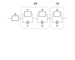
- FIG. 8 is a schematic diagram illustrating an example of an equivalent circuit model of the storage battery according to the first embodiment.
- FIG. 9 is a schematic diagram illustrating an example of learning data used to generate a machine learning model in the first embodiment.
- FIG. 10 is a schematic diagram showing an example of a plurality of machine learning models that can be used by the processing execution unit in the first modified example.
- FIG. 11 is a schematic diagram illustrating an example of a process performed by the process execution unit in analyzing measurement data for diagnosis of a storage battery in the first modified example.
- Fig. 1 shows an example of a diagnostic system 1 according to the first embodiment.
- the diagnostic system 1 includes a storage battery 2 to be diagnosed and a diagnostic device 3.
- the storage battery 2 is mounted on, for example, a battery-mounted device (not shown).
- Examples of the battery-mounted device on which the storage battery 2 is mounted include a transport vehicle for a factory such as an AGV (Automatic Guided Vehicle), a stationary power supply device, a smartphone, a vehicle such as an electric vehicle, a robot, a drone, and the like.
- AGV Automatic Guided Vehicle
- the storage battery 2 is, for example, a secondary battery such as a lithium ion secondary battery.
- the storage battery 2 may be formed from a single cell (single battery), or may be a battery module or cell block formed by electrically connecting a plurality of single cells.
- the plurality of single cells may be electrically connected in series in the storage battery 2, or may be electrically connected in parallel in the storage battery 2.
- the storage battery 2 may be formed with both a series connection structure in which a plurality of single cells are connected in series, and a parallel connection structure in which a plurality of single cells are connected in parallel.
- the storage battery 2 may be either a battery string or a battery array in which a plurality of battery modules are electrically connected.
- the diagnostic system 1 includes a power supply circuit 5, a current detection circuit 6, a voltage detection circuit 7, and a temperature sensor 8.
- the power supply circuit 5 is capable of outputting power to the storage battery 2.
- the power supply circuit 5 is used only in diagnosing the storage battery 2.
- the power supply circuit 5 is used not only in diagnosing the storage battery 2 but also in charging the storage battery 2.
- the output state of power from the power supply circuit 5 in diagnosing the storage battery 2 is different from the output state of power from the power supply circuit 5 in charging the storage battery 2.
- the current detection circuit 6 detects the current I flowing through the storage battery 2, for example, detecting the input current to the storage battery 2.
- the voltage detection circuit 7 detects the voltage V applied to the storage battery 2, for example, detecting the terminal voltage of the storage battery 2.
- the temperature sensor 8 detects the temperature T of the storage battery 2.
- the current detection circuit 6, the voltage detection circuit 7, and the temperature sensor 8 constitute a detection unit that detects parameters related to the storage battery 2.
- the diagnostic device 3 diagnoses the deterioration state, etc. of the storage battery 2 to be diagnosed.
- the diagnostic device 3 is a processing device (computer) such as a server, and includes a processing execution unit 11 such as a processing circuit, and a storage unit 12.
- the diagnostic device 3 includes a processor or integrated circuit, etc., and a storage medium such as a memory.
- the processor or integrated circuit, etc. includes any of a CPU (Central Processing Unit), an ASIC (Application Specific Integrated Circuit), a GPU (Graphics Processing Unit), a microcomputer, an FPGA (Field Programmable Gate Array), and a DSP (Digital Signal Processor), etc.
- the diagnostic device 3 may be provided with only one processor, etc., or may be provided with multiple processors, etc. Also, the diagnostic device 3 may be provided with only one storage medium, or may be provided with multiple storage media.
- the processor or integrated circuit, etc. performs processing, for example, by executing a program stored in the storage medium.
- a processor or the like performs processing of the processing execution unit 11, which is a processing circuit, and a storage medium functions as the storage unit 12.
- the processing execution unit 11 performs processing, which will be described later, by, for example, executing a diagnostic program stored in the storage unit 12.
- the diagnostic device 3 is configured from multiple processing devices (computers), such as multiple servers, and the processors of the multiple processing devices work together to perform the processing described below by the processing execution unit 11.
- at least a part of the diagnostic device 3 is configured from a cloud server in a cloud environment.
- the infrastructure of the cloud environment is configured from a virtual processor, such as a virtual GPU, and a cloud memory.
- the virtual processor then performs at least a part of the processing performed by the processing execution unit 11, which will be described below.
- the cloud memory then functions as the storage unit 12.
- the diagnostic system 1 may be provided with a user interface.
- the user of the diagnostic system 1 inputs operations related to the diagnosis of the diagnostic system 1 into the user interface.
- the user interface is provided with any of a button, mouse, touch panel, keyboard, etc. as an operation unit through which operations are input by the user.
- the user interface is also provided with a notification unit that notifies information related to the diagnosis of the diagnostic system 1.
- the notification unit notifies information by either displaying a screen or emitting a sound.
- the user interface may be mounted on a processing device constituting the diagnostic device 3, or may be provided separately from the processing device constituting the diagnostic device 3.
- FIG. 2 is a flowchart showing an example of a process performed by the process execution unit 11 in measuring diagnostic measurement data for the storage battery 2.
- the process execution unit 11 controls the output from the power supply circuit 5 to start inputting a pseudo-random pulse signal of the current I from the power supply circuit 5 to the storage battery 2 (S101).
- a pseudo-random pulse signal of the current I is generated in the power supply circuit 5, and the power supply circuit 5 outputs the generated pseudo-random pulse signal to the storage battery 2.
- the pseudo-random pulse signal does not necessarily have to be generated by the power supply circuit 5.
- a drive circuit switching circuit
- the processing execution unit 11 controls the output from the power supply circuit 5 to output an output current at a constant current value over time from the power supply circuit 5 to the storage battery 2.
- the drive circuit can be switched between a non-shunt state in which the entire output current from the power supply circuit 5 is input to the storage battery 2, and a shunt state in which a part of the output current from the power supply circuit 5 is shunted and the shunted part becomes a bypass current that is not input to the storage battery 2.
- the processing execution unit 11 controls the drive of the drive circuit and controls the switching of the drive circuit between the non-shunt state and the shunt state to input the pseudo-random pulse signal to the storage battery 2.
- the pseudorandom pulse signal of the current I input to the storage battery 2 includes a plurality of pulses p, and each of the plurality of pulses p has a specified pulse width and pulse height. At least one of the plurality of pulses p has a pulse width different from the other pulses p. In addition, the plurality of pulses p have the same or approximately the same pulse height with respect to each other. Therefore, in the pseudorandom pulse signal input to the storage battery 2, the amplitude Ip of the current I is constant or approximately constant over time.
- the current I changes over time between a current value (first current value) I ⁇ and a current value (second current value) I ⁇ +Ip that is larger in amplitude Ip than the current value I ⁇ .
- the current value I ⁇ may be zero or may be a value greater than zero.
- the processing execution unit 11 measures the time change of the current I and voltage V of the storage battery 2 while a pseudo-random pulse signal of the current I is being input to the storage battery 2 (S102). While the pseudo-random pulse signal is being input to the storage battery 2, the current detection circuit 6 detects the current I of the storage battery 2, and the voltage detection circuit 7 detects the voltage V of the storage battery 2 at each of a plurality of mutually different time points.
- the processing execution unit 11 measures the time change of the current I of the storage battery 2 based on the detection results by the current detection circuit 6 at the plurality of time points, and measures the time change of the voltage V of the storage battery 2 based on the detection results by the voltage detection circuit 7 at the plurality of time points. Note that while the pseudo-random pulse signal is being input to the storage battery 2, the time change of the pseudo-random pulse signal shown in the example of FIG. 3 is measured as the measurement result Itar(t) of the time change of the current I of the storage battery 2.
- the processing execution unit 11 measures the temperature T and SOC ⁇ of the storage battery 2 in addition to the time changes of the current I and voltage V of the storage battery 2 (S103).
- the temperature sensor 8 detects the temperature T of the storage battery 2 during the period in which the pseudo-random pulse signal is input to the storage battery 2, or at a certain point in time immediately before or after that period.
- the processing execution unit 11 then calculates the value of the temperature T detected by the temperature sensor 8 as the measurement result Ttar of the temperature T of the storage battery 2.
- the temperature sensor 8 detects the temperature T of the storage battery 2 at each of multiple points in time that are different from each other while the pseudo-random pulse signal is input to the storage battery 2.
- the processing execution unit 11 calculates the average value or median value of the values of the temperature T detected by the temperature sensor 8 at the multiple points in time as the measurement result Ttar of the temperature T of the storage battery 2.
- the processing execution unit 11 when measuring the SOC ⁇ of the storage battery 2, measures the open circuit voltage (OCV) of the storage battery 2 at the time of diagnosis based on the detection results by the current detection circuit 6 and the voltage detection circuit 7 while a pseudo-random pulse is being input to the storage battery 2. At this time, the processing execution unit 11 measures the closed circuit voltage (CCV) of the storage battery 2 at the time of diagnosis from the detection result by the voltage detection circuit 7, and calculates the open circuit voltage of the storage battery 2 using the measurement result of the closed circuit voltage, the detection result by the current detection circuit 6, and the resistance component of the storage battery 2.
- OCV open circuit voltage
- CCV closed circuit voltage
- the resistance component of the storage battery 2 used to calculate the open circuit voltage is calculated based on the estimated result of the resistance component of the storage battery 2 in the previous diagnosis, etc. Then, the processing execution unit 11 calculates the value of the SOC ⁇ of the storage battery 2 at the time of diagnosis as the measurement result ⁇ tar for SOC ⁇ based on the measurement result of the open circuit voltage of the storage battery 2 and the relationship between the open circuit voltage of the storage battery 2 and the SOC ⁇ stored in the memory unit 12.
- the value of SOC ⁇ of the storage battery 2 at the time of diagnosis is calculated as the measurement result ⁇ tar for SOC ⁇ based on the value of SOC ⁇ of the storage battery 2 at a predetermined time point before the diagnosis and the time history of charging and discharging the storage battery 2 from the predetermined time point to the time of diagnosis.
- the processing execution unit 11 may receive information on the SOC of the storage battery 2 from the power supply circuit 5 or the storage battery 2.
- the measured measurement data includes measurement results Itar(t) and Vtar(t) of the time change of the current I and voltage V of the storage battery 2 measured while a pseudo-random pulse signal is being input to the storage battery 2.
- the measured measurement data also includes measurement results Ttar and ⁇ tar of the temperature T and SOC ⁇ of the storage battery 2 measured during diagnosis.
- the processing execution unit 11 stops the input of the pseudo-random pulse signal of the current I from the power supply circuit 5 to the storage battery 2 by controlling the output from the power supply circuit 5 (S104). This ends the processing of the example of FIG. 2.
- FIG. 4 illustrates an example of processing performed by the processing execution unit 11 in analyzing the diagnostic measurement data for the storage battery 2.
- the processing execution unit 11 performs data processing using the measurement results Itar(t) and Vtar(t) of the time changes in the current I and voltage V of the storage battery 2 included in the measurement data (S111). Then, by the data processing of S111, the processing execution unit 11 generates target electrical characteristic data Ytar(N) of the storage battery 2 based on the measurement results Itar(t) and Vtar(t) of the time changes in the current I and voltage V of the storage battery 2.
- FIG. 5 is a flowchart showing an example of the data processing in S111 of FIG. 4, i.e., the processing performed by the processing execution unit 11 in generating the target electrical characteristic data Ytar(N) of the storage battery 2.
- the processing execution unit 11 normalizes the measurement result Vtar(t) of the time change of the voltage V by using the amplitude Ip of the current I in the measured time change of the current I (S121).
- the processing execution unit 11 normalizes the measurement result Vtar(t) of the time change of the voltage V, for example, by dividing the measured value of the voltage V at each of the multiple time points indicated by the measurement result Vtar(t) of the time change of the voltage V by the amplitude Ip of the current I.
- the processing execution unit 11 normalizes the measurement result Vtar(t) of the time change of the voltage V to generate normalized time series data Ytar(t) for the storage battery 2 to be diagnosed.
- the normalized time series data Ytar(t) indicates the value of the normalized parameter Y for each of the multiple time points at which the current I and voltage V of the storage battery 2 were measured (detected) in the measurement of the measurement data.
- the normalized parameter Y corresponds to a parameter obtained by dividing the voltage V of the storage battery 2 by the amplitude Ip of the current I in the time change of the measured current I.
- the processing execution unit 11 extracts values of the normalization parameter Y at multiple mutually different specified time points from the generated normalized time series data Ytar(t) (S122).
- the number of multiple specified time points extracted from the normalized time series data Ytar(t) is less than the number of multiple time points at which the current I and voltage V of the storage battery 2 were measured in the measurement of the measurement data.
- the processing execution unit 11 arranges the extracted values of the normalization parameter Y at the multiple specified time points in a specified order (S123). At this time, the specified order in which the values at the multiple specified time points are arranged is set based on the order parameter N.
- the processing execution unit 11 performs the processes of S122 and S123 as described above to generate target electrical characteristic data Ytar(N) of the storage battery 2 that is the diagnosis target. Since the target electrical characteristic data Ytar(N) of the storage battery 2 is generated as described above, the target electrical characteristic data Ytar(N) shows the extracted values of the normalization parameter Y at multiple specified time points arranged in a specified order based on the order parameter N. Furthermore, since the target electrical characteristic data Ytar(N) is generated as described above, the target electrical characteristic data Ytar(N) is data based on the measurement results Itar(t), Vtar(t) of the time changes in the current I and voltage V of the storage battery 2 that are included in the measurement data.
- the number of data points at which the value of the normalized parameter Y is indicated in the normalized time series data Ytar(t) is the same as the number of time points at which the current I and voltage V of the storage battery 2 were measured in the measurement of the measurement data
- the number of data points at which the value of the normalized parameter Y is indicated in the target electrical characteristic data Ytar(N) is the same as the number of specified time points extracted from the normalized time series data Ytar(t). Therefore, the number of data points at which the value of the normalized parameter Y is indicated in the target electrical characteristic data Ytar(N) is reduced from the number of data points at which the value of the normalized parameter Y is indicated in the normalized time series data Ytar(t).
- FIG. 6 illustrates an example of the processing of S122 and S123 in FIG. 5.
- the normalized time series data Ytar(t) described above is shown in a graph with the horizontal axis representing time t and the vertical axis representing the normalized parameter Y
- the target electrical characteristic data Ytar(N) described above is shown in a graph with the horizontal axis representing the order parameter N and the vertical axis representing the normalized parameter Y.
- the processing execution unit 11 extracts values indicated by open circles, open diamonds, and open crosses as values of the normalized parameter Y at multiple specified time points through the processing of S122.
- the values indicated by the open circles are extracted by extracting the values of the normalization parameter Y at equal intervals in the time interval (first time interval) X ⁇ between time t ⁇ 1 and time t ⁇ k (k is an integer of 2 or more) that follows time t ⁇ 1.
- the values indicated by the open diamonds are extracted by extracting the values of the normalization parameter Y at equal intervals in the time interval (second time interval) X ⁇ that is greater than the time interval X ⁇ between time t ⁇ 1 and time t ⁇ m (m is an integer of 2 or more) that follows time t ⁇ 1.
- the values indicated by the open crosses are extracted by extracting the values of the normalization parameter Y at equal intervals in the time interval (third time interval) X ⁇ that is greater than the time interval X ⁇ between time t ⁇ 1 and time t ⁇ n (n is an integer of 2 or more) that follows time t ⁇ 1.
- time interval X ⁇ between time t ⁇ 1 and time t ⁇ n (n is an integer of 2 or more) that follows time t ⁇ 1.
- time t ⁇ 1 and t ⁇ 1 is a time point later than time t ⁇ k
- time t ⁇ 1 is a time point between time t ⁇ 1 and time t ⁇ m.
- time t ⁇ n is a point in time later than time t ⁇ m.
- the processing execution unit 11 by the processing of S123, arranges the values indicated by the open circles in order of earliest time t, and arranges the values indicated by the open diamonds in order of earliest time t on the side where the order parameter N is greater than the values indicated by the open circles.
- the processing execution unit 11 then arranges the values indicated by the open crosses in order of earliest time t on the side where the order parameter N is greater than the values indicated by the open diamonds. For this reason, in the target electrical characteristic data Ytar(N), the values of the normalization parameter Y are arranged in the order of times t ⁇ 1, ... t ⁇ k from the side where the order parameter N is small, and the values of the normalization parameter Y are arranged in the order of times t ⁇ 1, ...
- the values of the normalization parameter Y are arranged in the order of time t ⁇ 1, ... t ⁇ n, from the side where the order parameter N is larger than the values of the normalization parameter Y at times t ⁇ 1 to t ⁇ m.
- the values of the normalization parameter Y at the order parameters N1 to Nk, Nk+1 to Nk+m, and Nk+m+1 to Nk+m+n correspond to the values of the normalization parameter Y at times t ⁇ 1 to t ⁇ k, t ⁇ 1 to t ⁇ m, and t ⁇ 1 to t ⁇ n in the normalized time series data Ytar(t), respectively.
- the times t ⁇ 1, t ⁇ 1, and t ⁇ 1 are different from each other, but in one example, the times t ⁇ 1, t ⁇ 1, and t ⁇ 1 may be the same from each other.
- the values of the normalized parameter Y are extracted at equal intervals of the time interval X ⁇ between the times t ⁇ 1 and t ⁇ k
- the values of the normalized parameter Y are extracted at equal intervals of the time interval X ⁇ larger than the time interval X ⁇ between the times t ⁇ 1 and t ⁇ m
- the values of the normalized parameter Y are extracted at equal intervals of the time interval X ⁇ larger than the time interval X ⁇ between the times t ⁇ 1 and t ⁇ n.
- the times t ⁇ 1, t ⁇ 1, and t ⁇ 1 may be the start times of input of a pseudo-random pulse signal of a current to the storage battery 2.
- the processing execution unit 11 uses the machine learning model Ma to estimate the internal state of the storage battery 2 from the target electrical characteristic data Ytar(N) of the storage battery 2 described above and the measurement results Ttar, ⁇ tar of the temperature T and SOC ⁇ of the storage battery 2 indicated by the measurement data (S112).
- the machine learning model Ma used in S112 is stored in the storage unit 12 and is generated (constructed) as described below.
- the processing execution unit 11 inputs the target electrical characteristic data Ytar(N) based on the measurement results Itar(t) and Vtar(t) of the time changes of the current I and voltage V of the storage battery 2, and the measurement results Ttar and ⁇ tar of the temperature T and SOC ⁇ of the storage battery 2 to the machine learning model Ma.
- the machine learning model Ma outputs the internal state of the storage battery 2 corresponding to the input target electrical characteristic data Ytar(N) and the measurement results Ttar and ⁇ tar.
- the machine learning model Ma outputs the value of a parameter indicating the internal state of the storage battery 2 as the internal state of the storage battery 2, and outputs, for example, the value of a circuit parameter ⁇ set in an equivalent circuit model of the storage battery 2 including the resistance component of the storage battery 2.
- the processing execution unit 11 estimates the internal state of the storage battery 2 based on the output result from the machine learning model Ma. In one example, the processing execution unit 11 estimates the resistance component of the storage battery 2 as the internal state of the storage battery 2 based on the value of the circuit parameter ⁇ output from the machine learning model Ma. For example, the value of the resistance component of storage battery 2 output from machine learning model Ma as the value of circuit parameter ⁇ is estimated as the value of the resistance component of storage battery 2 in real time.
- the input layer of the machine learning model Ma receives the electrical characteristic data Y(N) of the storage battery 2, such as the target electrical characteristic data Ytar(N) described above.
- the electrical characteristic data Y(N) is data based on the current time series data I(t) and voltage time series data V(t) of the storage battery 2.
- the current time series data I(t) indicates the time change of the current I of the storage battery 2 when a pseudo-random pulse signal of the current I is input to the storage battery 2, similar to the measurement result Itar(t) of the time change of the current I included in the measurement data
- the voltage time series data V(t) indicates the time change of the voltage V of the storage battery 2 when a pseudo-random pulse signal of the current I is input to the storage battery 2, similar to the measurement result Vtar(t) of the time change of the voltage V included in the measurement data.
- the electrical characteristic data Y(N) is generated based on the current time series data I(t) and the voltage time series data V(t) in a manner similar to the generation of the target electrical characteristic data Ytar(N) using the measurement results Itar(t) and Vtar(t) for the time changes in the current I and voltage V of the storage battery 2 contained in the measurement data.
- the value of the normalized parameter Y is input to the machine learning model Ma for each value of the order parameter N.
- the target electrical characteristic data Ytar(N) generated as in the example of FIG. 6 is input to the machine learning model Ma as the electrical characteristic data Y(N)
- the value of the normalized parameter Y for each of the order parameters N1 to Nk+m+n is input to the machine learning model Ma.
- the temperature T and SOC ⁇ of the storage battery 2 such as the measurement results Ttar and ⁇ tar, indicated by the measurement data, are input to the input layer of the machine learning model Ma.
- the electrical characteristic data Y(N) and the like are input to the machine learning model Ma
- processing is performed in the intermediate layer, and the value of a parameter indicating the internal state of the storage battery 2, such as the value of the circuit parameter ⁇ of the equivalent circuit model of the storage battery 2, is output from the output layer.
- a parameter indicating the internal state of the storage battery 2 such as the value of the circuit parameter ⁇ of the equivalent circuit model of the storage battery 2
- multiple circuit parameters ⁇ are set in an equivalent circuit model of the storage battery 2
- electrical characteristic data Y(N) and the like are input, so that the machine learning model Ma outputs values for each of the multiple circuit parameters ⁇ .
- FIG. 8 illustrates an example of an equivalent circuit model of the storage battery 2.
- resistances R0, R1, R2, and R3, which are resistance components, and capacitances C1, C2, and C3, which are capacity components, are set as the circuit parameter ⁇ .
- the resistances R1 and R2 are the resistance components of the negative electrode of the storage battery 2
- the resistance R3 is the resistance component of the positive electrode of the storage battery 2.
- the machine learning model Ma outputs values for each of the resistances R0 to R3 and capacitances C1 to C3, which are the circuit parameter ⁇ .
- Patent Document 4 JP Patent Publication No. 2017-106889
- the machine learning model Ma used in the process of S112 is generated (constructed) using learning data consisting of a large number of data sets.
- Each data set of the learning data indicates data from past diagnoses of a storage battery similar to the storage battery 2 to be diagnosed.
- Each data set indicates electrical characteristic data Y(N) similar to the target electrical characteristic data Ytar(N).
- the electrical characteristic data Y(N) indicated in each data set is generated, for example, based on current time series data I(t) and voltage time series data V(t) measured in a past diagnosis while a pseudo-random pulse signal of current I was input.
- the electrical characteristic data Y(N) of each data set is generated in the same manner as the generation of the target electrical characteristic data Ytar(N) using the measurement results Itar(t) and Vtar(t) of the time changes in the current I and voltage V of the storage battery 2 included in the measurement data.
- each of the data sets shows the values of temperature T and SOC ⁇ .
- the measured values in a past diagnosis of a storage battery similar to storage battery 2 are shown as the values of temperature T and SOC ⁇ .
- the values of temperature T and SOC ⁇ shown in each of the data sets are measured in the same manner as the measurement of temperature T and SOC ⁇ of storage battery 2 described above.
- each of the data sets shows the value of circuit parameter ⁇ of the equivalent circuit model. In generating each of the data sets, the value of circuit parameter ⁇ is calculated using the aforementioned current time series data I(t) and voltage time series data V(t) measured while a pseudo-random pulse signal of current I is input.
- the impedance of the storage battery at each of a plurality of frequencies is measured by performing Fourier analysis on the current time series data I(t) and the voltage time series data V(t) in calculating the value of the circuit parameter ⁇ , and the frequency characteristics of the impedance of the storage battery are measured.
- the measurement results of the frequency characteristics of the impedance of the storage battery can be shown, for example, in a complex impedance plot (Cole-Cole plot). Note that a method of calculating the frequency characteristics of the impedance of the storage battery using the current time series data and voltage time series data of the storage battery is shown in Patent Document 3 (JP Patent Publication 2014-126532).
- the frequency characteristics of the impedance of the storage battery may be calculated in the same manner as in Patent Document 3 in generating each data set.
- the value of the circuit parameter ⁇ is calculated using the measurement results of the impedance frequency characteristics and the equivalent circuit model of the storage battery.
- the equivalent circuit model an arithmetic expression or the like is shown for calculating the impedance of the storage battery from the set circuit parameter ⁇ , and for example, an expression for calculating each of the real component and the imaginary component of the impedance of the storage battery using the circuit parameter ⁇ and frequency, etc. is shown.
- a fitting calculation is performed using the aforementioned arithmetic expression shown in the equivalent circuit model and the measurement results of the impedance frequency characteristics of the storage battery.
- a fitting calculation is performed using the circuit parameter ⁇ of the equivalent circuit model as a variable, and the circuit parameter ⁇ that becomes the variable is calculated.
- the value of the circuit parameter ⁇ that becomes the variable is determined so that the difference between the impedance calculation result using the arithmetic expression shown in the equivalent circuit model and the impedance measurement result is as small as possible.
- the measurement results of the frequency characteristics of the impedance of the storage battery and a method of performing fitting calculations using an equivalent circuit model of the storage battery to calculate the circuit parameters of the equivalent circuit model are shown in Patent Document 4.
- parameters indicating the internal state of the storage battery are associated with electrical characteristic data Y(N) based on current time series data I(t) and voltage time series data V(t). Also, in each data set, for a storage battery similar to the previously diagnosed storage battery 2, parameters indicating the internal state of the storage battery, such as circuit parameter ⁇ , are associated with temperature T and SOC ⁇ .
- FIG. 9 shows an example of training data used to generate a machine learning model Ma.
- the training data is composed of j data sets (j is an integer equal to or greater than 2).
- the values of parameter sets ⁇ 1 to ⁇ j of the circuit parameter ⁇ are associated with electrical characteristic data Y1(N) to Yj(N), respectively.
- the values of parameter sets ⁇ 1 to ⁇ j of the circuit parameter ⁇ are associated with values T1 to Tj of temperature T and values ⁇ 1 to ⁇ j of SOC ⁇ , respectively.
- a part of many data sets of learning data is used as a training data set to train the model by deep learning.
- a neural network is trained as the model.
- the model is trained by supervised learning in which the value of the circuit parameter ⁇ shown in each training data set is given as the correct answer.
- the model learns the association of parameters indicating the internal state of the storage battery, such as the electrical characteristic data Y(N) shown in the training data set, the circuit parameter ⁇ with respect to the temperature T and SOC ⁇ .
- a portion of the training data set is used as an evaluation dataset to evaluate the trained model.
- the electrical characteristic data Y(N) and the values of temperature T and SOC ⁇ for each of the evaluation datasets are input to the trained model.
- the value of the circuit parameter ⁇ output as the output result from the trained model is compared with the calculation result of the circuit parameter ⁇ in an actual past diagnosis. Then, by performing the above-mentioned comparison for each of the training datasets, the validity of the output result from the model relative to the calculation result in the actual diagnosis is determined.
- the trained model is stored in the memory unit 12 as a machine learning model Ma.
- a training dataset is added, and the model is trained as described above using the added training dataset. Then, learning of the model using the training dataset and evaluation of the model using the evaluation dataset are repeated until the validity of the output results from the model relative to the calculation results in the actual diagnosis is equal to or higher than the reference level in the model evaluation.
- the processing execution unit 11 estimates the degree of deterioration of the storage battery 2 based on the internal state of the storage battery 2 including the circuit parameter ⁇ estimated using the machine learning model Ma (S113). In estimating the degree of deterioration, the processing execution unit 11 calculates the ratio ⁇ between the positive electrode resistance and the negative electrode resistance of the storage battery 2 based on the estimation result for the resistance component of the storage battery 2 set as the circuit parameter ⁇ .
- the processing execution unit 11 calculates the ratio ⁇ by taking the sum of the values of the resistances R1 and R2 as the negative electrode resistance and the value of the resistance R3 as the positive electrode resistance.
- the processing execution unit 11 estimates the degree of deterioration of the storage battery 2 based on the calculated ratio ⁇ .
- the estimation of the deterioration degree in S113 may be performed based on the measurement results Ttar, ⁇ tar, etc. of the temperature T and SOC ⁇ of the storage battery 2 in addition to the ratio ⁇ described above.
- the processing execution unit 11 corrects the calculated value of the ratio ⁇ between the positive electrode resistance and the negative electrode resistance calculated as described above to a correction value at the reference temperature Tref and the reference SOC ⁇ ref based on the measurement results Ttar, ⁇ tar, etc. of the temperature T and SOC ⁇ of the storage battery 2. Then, the processing execution unit 11 estimates the degree of deterioration of the storage battery 2 based on the corrected correction value of the ratio ⁇ . Also, the processing of S113 does not need to be performed. In this case, the analysis process of the diagnostic measurement data is completed by estimating the internal state of the storage battery 2, such as the circuit parameter ⁇ , in S112.
- the processing execution unit 11 which is a processing circuit, measures the time change in the current I and voltage V of the storage battery 2 while a pseudo-random pulse signal of the current I is being input to the storage battery 2. Then, using a machine learning model Ma that outputs the internal state of the storage battery 2 from an input of electrical characteristic data Y(N) based on the current time series data I(t) and voltage time series data V(t) of the storage battery 2, the processing execution unit 11 inputs target electrical characteristic data Ytar(N) based on the measurement results Itar(t) and Vtar(t) of the time change in the current I and voltage V to the machine learning model Ma as electrical characteristic data Y(N).
- the processing execution unit 11 estimates the internal state of the storage battery 2 based on the output result from the machine learning model Ma in response to the input of the target electrical characteristic data Ytar(N). Since the internal state of the storage battery 2 is estimated as described above, the internal state of the storage battery 2 can be estimated without performing Fourier analysis of the measurement results Itar(t) and Vtar(t) of the time changes in the current I and voltage V of the storage battery 2, and fitting calculations using the measurement results and equivalent circuit model of the frequency characteristics of the impedance of the storage battery 2. This reduces the effort required to analyze the measurement data including the measurement results Itar(t) and Vtar(t) of the time changes in the current I and voltage V of the storage battery 2. This also makes it possible to shorten the time required to analyze the measurement data.
- the processing execution unit 11 generates normalized time series data Ytar(t) by normalizing the measurement result Vtar(t) of the time change of the voltage V using the amplitude Ip of the measured time change of the current I in the data processing of S111. Then, the processing execution unit 11 extracts values at multiple specified time points that are different from each other from the generated normalized time series data Ytar(t) and arranges the extracted values at the multiple specified time points in a specified order to generate the target electrical characteristic data Ytar(N) to be input to the machine learning model Ma.
- the amount of data input to the machine learning model Ma is reduced compared to a case where the measurement results Itar(t) and Vtar(t) of the time changes of the current I and voltage V of the storage battery 2 are input directly to the machine learning model Ma, and the amount of data processed using the machine learning model Ma is reduced.
- the machine learning model Ma outputs a circuit parameter ⁇ that is set in an equivalent circuit model of the storage battery 2 including the resistance component of the storage battery 2, based on the input of the electrical characteristic data Y(N).
- the processing execution unit 11 estimates the resistance component of the storage battery 2 as the internal state of the storage battery 2 based on the output result from the machine learning model Ma in response to the input of the target electrical characteristic data Ytar(N). Therefore, the resistance component of the storage battery 2 is appropriately estimated as the internal state of the storage battery 2 using the machine learning model Ma.
- the processing execution unit 11 calculates the ratio ⁇ between the positive electrode resistance and the negative electrode resistance of the storage battery 2 based on the estimation result for the resistance component of the storage battery 2. The processing execution unit then estimates the degree of deterioration of the storage battery 2 based on the calculated ratio ⁇ . Therefore, the degree of deterioration of the storage battery 2 is appropriately estimated based on the amount of change in the ratio ⁇ between the positive electrode resistance and the negative electrode resistance from the start of use of the storage battery 2, etc.
- the processing execution unit 11 measures the temperature T and SOC ⁇ of the storage battery 2 during diagnosis. Then, the processing execution unit 11 estimates the internal state of the storage battery 2 by inputting the measurement results Ttar, ⁇ tar for the temperature T and SOC ⁇ of the storage battery 2 in addition to the target electrical characteristic data Ytar(N) to the machine learning model Ma. As a result, the internal state of the storage battery 2 is appropriately estimated taking into account the temperature T and SOC ⁇ of the storage battery 2 while the time changes of the current I and voltage V are being measured.
- the machine learning model Ma outputs a parameter indicating the internal state of the storage battery 2, such as a circuit parameter ⁇ , by inputting one of the temperature T and SOC ⁇ in addition to the electrical characteristic data Y(N).
- the processing execution unit 11 estimates the internal state of the storage battery 2 by inputting one of the measurement results Ttar and ⁇ tar of the temperature T and SOC ⁇ to the machine learning model Ma in addition to the target electrical characteristic data Ytar(N) based on the measurement results Itar(t) and Vtar(t) of the time changes of the current I and the voltage V.
- the machine learning model Ma outputs a parameter indicating the internal state of the storage battery 2, such as a circuit parameter ⁇ , by inputting only the electrical characteristic data Y(N).
- the processing execution unit 11 estimates the internal state of the storage battery 2 by inputting only the target electrical characteristic data Ytar(N) based on the measurement results Itar(t) and Vtar(t) of the time changes of the current I and the voltage V to the machine learning model Ma.
- the internal state of the storage battery 2 is estimated without performing Fourier analysis of the measurement results Itar(t) and Vtar(t) of the time changes in the current I and voltage V of the storage battery 2, and fitting calculations using the measurement results and equivalent circuit model of the impedance frequency characteristics of the storage battery 2. This reduces the effort required to analyze measurement data including the measurement results Itar(t) and Vtar(t) of the time changes in the current I and voltage V of the storage battery 2.
- the machine learning model Ma is generated (constructed) using learning data consisting of a large number of data sets, and in each of the large number of data sets, parameters indicating the internal state of the storage battery, such as the circuit parameter ⁇ , are associated with electrical characteristic data Y(N) based on the current time series data I(t) and voltage time series data V(t) for a storage battery similar to the storage battery 2 previously diagnosed.
- the processing execution unit 11 can use multiple machine learning models Ma1 to Maq (q is an integer of 2 or more) as the machine learning model Ma that outputs the internal state of the storage battery 2 from the input of the electrical characteristic data Y(N).
- FIG. 10 shows an example of multiple machine learning models Ma1 to Maq that can be used by the processing execution unit 11 in this modified example.
- each of the machine learning models Ma1 to Maq outputs the internal state of the storage battery 2 from the input of the electrical characteristic data Y(N) based on the current time series data I(t) and voltage time series data V(t) of the storage battery 2.
- the SOC ⁇ of the storage battery 2 can be input to the input layer of each of the machine learning models Ma1 to Maq.
- the applicable temperature range ⁇ T of the multiple machine learning models Ma1 to Maq is different from one another.
- the applicable temperature range ⁇ T of the machine learning models Ma1, Ma2, ..., Maq is the temperature range ⁇ T of ⁇ T1, ⁇ T2, ..., ⁇ Tq, respectively.
- the processing execution unit 11 uses a machine learning model (additional machine learning model) Mb different from the machine learning models Ma1 to Maq to estimate the temperature range ⁇ T of the storage battery 2 from the target electrical characteristic data Ytar(N) of the storage battery 2 and the measurement result ⁇ tar of the SOC ⁇ of the storage battery 2 indicated by the measurement data (S114).
- the machine learning model Mb used in S114 is stored in the storage unit 12. Also, in this modified example, the temperature T of the storage battery 2 is not measured when measuring the measurement data.
- the processing execution unit 11 inputs the target electrical characteristic data Ytar(N) based on the measurement results Itar(t) and Vtar(t) of the time changes of the current I and voltage V of the storage battery 2, and the measurement result ⁇ tar of the SOC ⁇ of the storage battery 2 to the machine learning model Mb.
- the machine learning model Mb outputs the temperature range ⁇ T of the storage battery 2 corresponding to the input target electrical characteristic data Ytar(N) and the measurement result ⁇ tar as information on the temperature T of the storage battery 2.
- the processing execution unit 11 estimates the temperature range ⁇ T of the storage battery 2 based on the output result from the machine learning model Mb.
- the machine learning model Mb is used, which outputs information on the temperature T of the storage battery 2, such as the temperature range ⁇ T, from the input of electrical characteristic data Y(N), such as the target electrical characteristic data Ytar(N).
- the machine learning model Mb is generated (constructed) using learning data consisting of multiple data sets, similar to the machine learning models Ma1 to Maq. However, in each data set of the learning data used to generate the machine learning model Mb, information on the temperature T of the storage battery 2, such as the temperature range ⁇ T of the storage battery 2, is associated with the electrical characteristic data Y(N) based on the current time series data I(t) and the voltage time series data V(t).
- a portion of the data set is used as a training data set to train the model. Then, a portion of the data set is used as an evaluation data set to evaluate the model as described above.
- the process execution unit 11 performs a selection process from among the multiple machine learning models Ma1 to Maq based on the estimation result ⁇ Test for the temperature range ⁇ T estimated using the machine learning model (additional machine learning model) Mb (S115).
- one of the multiple machine learning models Ma1 to Maq is selected to input the target electrical characteristic data Ytar(N) based on the output result from the machine learning model Mb in response to the input of the target electrical characteristic data Ytar(N).
- a machine learning model (corresponding one of Ma1 to Maq) applicable to the temperature range ⁇ T corresponding to the estimation result ⁇ Test is selected from the machine learning models Ma1 to Maq.
- a machine learning model (corresponding one of Ma1 to Maq) applicable to the temperature range ⁇ T indicated by the information on the temperature T of the storage battery 2 output from the machine learning model Mb is selected from the machine learning models Ma1 to Maq.
- the processing execution unit 11 uses the selected one of the machine learning models Ma1 to Maq to estimate the internal state of the storage battery 2 from the target electrical characteristic data Ytar(N) of the storage battery 2 and the measurement result ⁇ tar of the SOC ⁇ of the storage battery 2 (S112A).
- the internal state of the storage battery 2 is estimated using the selected machine learning model (corresponding one of Ma1 to Maq). That is, in this modified example, the processing execution unit 11 inputs the target electrical characteristic data Ytar(N) and the measurement result ⁇ tar for the SOC ⁇ of the storage battery 2 to the selected machine learning model (corresponding one of Ma1 to Maq).
- the selected machine learning model (corresponding one of Ma1 to Maq) outputs the internal state of the storage battery 2 corresponding to the input target electrical characteristic data Ytar(N), etc.
- the process execution unit 11 estimates the internal state of the storage battery 2 based on the output result from the selected machine learning model (one of Ma1 to Maq). Note that, although not shown in FIG. 11, in this modified example, once the process execution unit 11 estimates the internal state of the storage battery 2 by the process of S112A, it may estimate the degree of deterioration of the storage battery 2 in a manner similar to the example in FIG. 4.
- the multiple machine learning models Ma1 to Maq have different applicable SOC ranges ⁇ .
- the temperature T of the storage battery 2 can be input to the input layer of each of the machine learning models Ma1 to Maq.
- each of the machine learning models Ma1 to Maq is generated (constructed) using learning data consisting of a large number of data sets, as with the machine learning model Ma, and in each of the large number of data sets, parameters indicating the internal state of the storage battery, such as circuit parameters ⁇ , are associated with electrical characteristic data Y(N) based on current time series data I(t) and voltage time series data V(t) for a storage battery similar to the storage battery 2 previously diagnosed.
- each of the machine learning models Ma1 to Maq is generated using only data sets in the applicable SOC range ⁇ described above.
- the process execution unit 11 uses the machine learning model Mb to estimate the SOC range ⁇ of the storage battery 2 from the target electrical characteristic data Ytar(N) of the storage battery 2 and the measurement result Ttar of the temperature T of the storage battery 2 indicated by the measurement data.
- the measurement of the measurement data does not involve measurement of the SOC ⁇ of the storage battery 2.
- the process execution unit 11 inputs the target electrical characteristic data Ytar(N) based on the measurement results Itar(t) and Vtar(t) of the time changes in the current I and voltage V of the storage battery 2, and the measurement result Ttar of the temperature T of the storage battery 2, to the machine learning model Mb.
- the machine learning model Mb outputs the SOC range ⁇ of the storage battery 2 corresponding to the input target electrical characteristic data Ytar(N) and measurement result Ttar as information regarding the SOC ⁇ of the storage battery 2.
- the processing execution unit 11 estimates the SOC range ⁇ of the storage battery 2 based on the output result from the machine learning model Mb. Therefore, in this modified example, a machine learning model Mb is used that outputs information about the SOC ⁇ of the storage battery 2, such as the SOC range ⁇ , from the input of the electrical characteristic data Y(N).
- the process execution unit 11 performs a selection process from multiple machine learning models Ma1 to Maq based on the estimation result ⁇ est for the SOC range ⁇ estimated using the machine learning model (additional machine learning model) Mb. At this time, a machine learning model (corresponding one of Ma1 to Maq) applicable to the SOC range ⁇ corresponding to the estimation result ⁇ est is selected from the machine learning models Ma1 to Maq.
- a machine learning model (corresponding one of Ma1 to Maq) applicable to the SOC range ⁇ indicated by the information on the SOC ⁇ of the storage battery 2 output from the machine learning model Mb is selected from the machine learning models Ma1 to Maq.
- the process execution unit 11 uses a selected one of the machine learning models Ma1 to Maq to estimate the internal state of the storage battery 2 from the target electrical characteristic data Ytar(N) of the storage battery 2 and the measurement result Ttar of the temperature T of the storage battery 2.
- the internal state of the storage battery 2 is estimated using the selected machine learning model (the corresponding one of Ma1 to Maq) in the same manner as the process of S112 in the example of FIG. 4.
- the multiple machine learning models Ma1 to Maq differ from each other in at least one of the applicable temperature range ⁇ T and SOC range ⁇ . That is, the machine learning models Ma1 to Maq differ from each other in the conditions for the applicable temperature range ⁇ T and SOC range ⁇ . And, only electrical characteristic data Y(N) can be input to each of the machine learning models Ma1 to Maq.
- each of the machine learning models Ma1 to Maq is generated (constructed) using learning data composed of a large number of data sets, as with the machine learning model Ma, and in each of the large number of data sets, parameters indicating the internal state of the storage battery, such as circuit parameters ⁇ , are associated with electrical characteristic data Y(N) based on current time series data I(t) and voltage time series data V(t) for a storage battery similar to the storage battery 2 previously diagnosed.
- each of the machine learning models Ma1 to Maq is generated using only datasets that satisfy the conditions for the applicable temperature range ⁇ T and SOC range ⁇ described above.
- the process execution unit 11 uses the machine learning model Mb to estimate the temperature range ⁇ T and SOC range ⁇ of the storage battery 2 from the target electrical characteristic data Ytar(N) of the storage battery 2.
- the temperature T and SOC ⁇ of the storage battery 2 are not measured when measuring the measurement data.
- the process execution unit 11 inputs only the target electrical characteristic data Ytar(N) based on the measurement results Itar(t) and Vtar(t) of the time changes in the current I and voltage V of the storage battery 2 to the machine learning model Mb.
- the machine learning model Mb outputs the temperature range ⁇ T and SOC range ⁇ of the storage battery 2 corresponding to the input target electrical characteristic data Ytar(N) as information on the temperature T and SOC ⁇ of the storage battery 2.
- the process execution unit 11 estimates the temperature range ⁇ T and SOC range ⁇ of the storage battery 2 based on the output results from the machine learning model Mb. Therefore, in this modified example, a machine learning model Mb is used that outputs information about the temperature T and SOC ⁇ of the storage battery 2 from the input of the electrical characteristic data Y(N).
- the process execution unit 11 performs a selection process from multiple machine learning models Ma1 to Maq based on the estimation results ⁇ Test, ⁇ est for the temperature range ⁇ T and SOC range ⁇ estimated using the machine learning model Mb.
- a machine learning model (corresponding one of Ma1 to Maq) that is applicable to the conditions for the temperature range ⁇ T and SOC range ⁇ that correspond to the estimation results ⁇ Test, ⁇ est is selected from the machine learning models Ma1 to Maq. That is, a machine learning model (one of Ma1 to Maq) that is applicable to both the temperature range ⁇ T and the SOC range ⁇ indicated by the information on the temperature T and SOC ⁇ of the storage battery 2 output from the machine learning model Mb is selected from the machine learning models Ma1 to Maq.
- the process execution unit 11 estimates the internal state of the storage battery 2 from the target electrical characteristic data Ytar(N) of the storage battery 2 using the selected one of the machine learning models Ma1 to Maq. At this time, the internal state of the storage battery 2 is estimated using the selected machine learning model (one of Ma1 to Maq) in the same manner as the process of S112 in the example of FIG. 4.
- each of the multiple machine learning models Ma1 to Maq outputs the internal state of the storage battery 2 from an input of electrical characteristic data (e.g., Y(N)), and the machine learning models Ma1 to Maq differ from each other in at least one of the applicable temperature range ⁇ T and SOC range ⁇ .
- a processing execution unit 11 such as a processing circuit selects one of the machine learning models Ma1 to Maq to input the target electrical characteristic data (e.g., Ytar(N)) based on information regarding at least one of the temperature T and SOC ⁇ of the storage battery 2.
- the machine learning model (additional machine learning model) Mb outputs information regarding at least one of the temperature T and SOC ⁇ of the storage battery 2 from an input of electrical characteristic data (e.g., Y(N)), and the processing execution unit 11 uses the machine learning model Mb to input the target electrical characteristic data (e.g., Ytar(N)) to the machine learning model Mb. Then, the processing execution unit 11 selects one of the multiple machine learning models Ma1 to Maq to input the target electrical characteristic data, based on the output result from the machine learning model Mb in response to the input of the target electrical characteristic data.
- electrical characteristic data e.g., Y(N)
- the processing execution unit 11 selects one of the multiple machine learning models Ma1 to Maq to input the target electrical characteristic data, based on the output result from the machine learning model Mb in response to the input of the target electrical characteristic data.
- the internal state of the storage battery 2 is estimated without performing Fourier analysis of the measurement results Itar(t) and Vtar(t) of the time changes in the current I and voltage V of the storage battery 2, and fitting calculations using the measurement results and equivalent circuit model of the frequency characteristics of the impedance of the storage battery 2. Therefore, as in the above-mentioned embodiment, the effort required for analyzing measurement data including the measurement results Itar(t) and Vtar(t) of the time changes in the current I and voltage V of the storage battery 2 is reduced.
- the machine learning models Ma1 to Maq and the machine learning model Mb can be used, such as the first modified example, it is possible to omit measurement of at least one of the temperature T and SOC ⁇ of the storage battery 2 in measuring diagnostic measurement data including the time changes in the current I and voltage V of the storage battery 2. This reduces the effort required for measuring diagnostic measurement data in diagnosing the storage battery 2.
- the target electrical characteristic data Ytar(N) etc. generated by the processing of S111 is input to the machine learning models Ma (Ma1 to Maq), Mb etc., but this is not limited to the above, as long as electrical characteristic data based on the measurement results Itar(t), Vtar(t) of the time changes of the current I and the voltage V is input to the machine learning models Ma, Mb etc.
- the waveforms themselves indicating the measurement results Itar(t), Vtar(t) of the time changes of the current I and the voltage V when a pseudo-random pulse signal is input to the storage battery 2 are input to the machine learning models Ma, Mb etc. as the target electrical characteristic data of the storage battery 2.
- the machine learning models Ma (Ma1 to Maq) output the internal state of the storage battery 2 from the input of the current time series data I(t) and voltage time series data V(t) of the storage battery 2 itself. Then, the machine learning model (additional machine learning model) outputs information about at least one of the temperature T and SOC ⁇ of the storage battery 2 from the input of the current time series data I(t) and the voltage time series data V(t) of the storage battery 2 itself.
- the internal state of the storage battery 2 is estimated using at least the machine learning model Ma in a manner similar to any of the previously described embodiments. Therefore, in this modified example, it is possible to omit measuring at least one of the temperature T and SOC ⁇ of the storage battery 2 when measuring diagnostic measurement data including changes over time in the current I and voltage V of the storage battery 2. This reduces the effort required to measure diagnostic measurement data when diagnosing the storage battery 2.
- the processing execution unit 11 performs the data processing of S111 in FIG. 4 in parallel with the measurement of the current and voltage of the storage battery 2 while the pseudo-random current pulse signal is being input.
- the processing execution unit 11 acquires the measurement values of the current and voltage only at a specified time point, such as a time point corresponding to the sequence parameter N.
- the processing execution unit 11 calculates a normalization parameter Y from the measurement values of the current and voltage only at the specified time point, and stores the calculated normalization parameter Y.
- the measurement values of the current and voltage are acquired and the normalization parameter Y is calculated only at a specified time point among all the measurement time points at which the current and voltage are measured. Therefore, it is possible to reduce the amount of data to be stored and transferred in the data processing for generating the target electrical characteristic data Ytar(N).
- the time changes in the current and voltage of the storage battery are measured while a pseudo-random pulse signal of current is being input to the storage battery. Then, using a machine learning model that outputs the internal state of the storage battery from an input of electrical characteristic data based on the current time series data and voltage time series data of the storage battery, target electrical characteristic data based on the measurement results of the time changes in current and voltage are input to the machine learning model as electrical characteristic data, and the internal state of the storage battery is estimated based on the output results from the machine learning model in response to the input of the target electrical characteristic data.
Landscapes
- Physics & Mathematics (AREA)
- General Physics & Mathematics (AREA)
- Tests Of Electric Status Of Batteries (AREA)
Priority Applications (4)
| Application Number | Priority Date | Filing Date | Title |
|---|---|---|---|
| PCT/JP2023/010348 WO2024189905A1 (ja) | 2023-03-16 | 2023-03-16 | 蓄電池の診断装置、診断システム及び診断方法 |
| JP2025506431A JPWO2024189905A1 (https=) | 2023-03-16 | 2023-03-16 | |
| EP23927524.1A EP4682561A4 (en) | 2023-03-16 | 2023-03-16 | BATTERY DIAGNOSTIC DEVICE, DIAGNOSTIC SYSTEM, AND DIAGNOSTIC METHOD |
| US19/223,172 US20250290988A1 (en) | 2023-03-16 | 2025-05-30 | Diagnosis apparatus, diagnosis system, and diagnosis method of storage battery |
Applications Claiming Priority (1)
| Application Number | Priority Date | Filing Date | Title |
|---|---|---|---|
| PCT/JP2023/010348 WO2024189905A1 (ja) | 2023-03-16 | 2023-03-16 | 蓄電池の診断装置、診断システム及び診断方法 |
Related Child Applications (1)
| Application Number | Title | Priority Date | Filing Date |
|---|---|---|---|
| US19/223,172 Continuation US20250290988A1 (en) | 2023-03-16 | 2025-05-30 | Diagnosis apparatus, diagnosis system, and diagnosis method of storage battery |
Publications (1)
| Publication Number | Publication Date |
|---|---|
| WO2024189905A1 true WO2024189905A1 (ja) | 2024-09-19 |
Family
ID=92754790
Family Applications (1)
| Application Number | Title | Priority Date | Filing Date |
|---|---|---|---|
| PCT/JP2023/010348 Ceased WO2024189905A1 (ja) | 2023-03-16 | 2023-03-16 | 蓄電池の診断装置、診断システム及び診断方法 |
Country Status (4)
| Country | Link |
|---|---|
| US (1) | US20250290988A1 (https=) |
| EP (1) | EP4682561A4 (https=) |
| JP (1) | JPWO2024189905A1 (https=) |
| WO (1) | WO2024189905A1 (https=) |
Citations (9)
| Publication number | Priority date | Publication date | Assignee | Title |
|---|---|---|---|---|
| JP2003222660A (ja) * | 1996-12-17 | 2003-08-08 | Matsushita Electric Ind Co Ltd | 電池の残存容量測定装置 |
| WO2012049852A1 (ja) * | 2010-10-14 | 2012-04-19 | トヨタ自動車株式会社 | 蓄電装置の診断装置、診断方法、および蓄電装置 |
| JP2014126532A (ja) | 2012-12-27 | 2014-07-07 | Waseda Univ | 電気化学システム |
| JP2016090346A (ja) | 2014-10-31 | 2016-05-23 | エンネット株式会社 | 電池診断装置および電池診断方法 |
| JP2017106889A (ja) | 2015-11-30 | 2017-06-15 | 積水化学工業株式会社 | 診断用周波数決定方法、蓄電池劣化診断方法、診断用周波数決定システムおよび蓄電池劣化診断装置 |
| JP2020020604A (ja) | 2018-07-30 | 2020-02-06 | トヨタ自動車株式会社 | 電池情報処理システム、二次電池の容量推定方法、ならびに、組電池、および、その組電池の製造方法 |
| WO2020090143A1 (ja) * | 2018-10-30 | 2020-05-07 | エンネット株式会社 | 電流パルス法による電池診断装置及び電池診断方法 |
| JP2022174885A (ja) * | 2021-05-12 | 2022-11-25 | 株式会社日立製作所 | 二次電池管理装置、二次電池管理方法およびプログラム |
| US11527786B1 (en) * | 2022-03-28 | 2022-12-13 | Eatron Technologies Ltd. | Systems and methods for predicting remaining useful life in batteries and assets |
Family Cites Families (6)
| Publication number | Priority date | Publication date | Assignee | Title |
|---|---|---|---|---|
| WO2020157961A1 (ja) * | 2019-02-01 | 2020-08-06 | 三菱電機株式会社 | 人工ニューラルネットワーク学習装置、歪み補償回路及び信号処理装置 |
| JP2021018171A (ja) * | 2019-07-22 | 2021-02-15 | 株式会社Jvcケンウッド | 劣化状態監視装置、劣化状態監視方法及びプログラム |
| JP7082603B2 (ja) * | 2019-12-25 | 2022-06-08 | 本田技研工業株式会社 | 機械学習装置、機械学習方法、充電率推定装置、および充電率推定システム |
| JP7634198B2 (ja) * | 2020-11-24 | 2025-02-21 | Fairy Devices株式会社 | 統計的機械学習のための時系列データの情報処理技術 |
| KR102861015B1 (ko) * | 2021-01-08 | 2025-09-17 | 주식회사 엘지에너지솔루션 | 배터리 관리 장치 및 방법 |
| JP2022136664A (ja) * | 2021-03-08 | 2022-09-21 | 本田技研工業株式会社 | 二次電池の開放電圧推定モデルの学習方法、開放電圧推定方法、および二次電池の状態推定方法 |
-
2023
- 2023-03-16 WO PCT/JP2023/010348 patent/WO2024189905A1/ja not_active Ceased
- 2023-03-16 JP JP2025506431A patent/JPWO2024189905A1/ja active Pending
- 2023-03-16 EP EP23927524.1A patent/EP4682561A4/en active Pending
-
2025
- 2025-05-30 US US19/223,172 patent/US20250290988A1/en active Pending
Patent Citations (9)
| Publication number | Priority date | Publication date | Assignee | Title |
|---|---|---|---|---|
| JP2003222660A (ja) * | 1996-12-17 | 2003-08-08 | Matsushita Electric Ind Co Ltd | 電池の残存容量測定装置 |
| WO2012049852A1 (ja) * | 2010-10-14 | 2012-04-19 | トヨタ自動車株式会社 | 蓄電装置の診断装置、診断方法、および蓄電装置 |
| JP2014126532A (ja) | 2012-12-27 | 2014-07-07 | Waseda Univ | 電気化学システム |
| JP2016090346A (ja) | 2014-10-31 | 2016-05-23 | エンネット株式会社 | 電池診断装置および電池診断方法 |
| JP2017106889A (ja) | 2015-11-30 | 2017-06-15 | 積水化学工業株式会社 | 診断用周波数決定方法、蓄電池劣化診断方法、診断用周波数決定システムおよび蓄電池劣化診断装置 |
| JP2020020604A (ja) | 2018-07-30 | 2020-02-06 | トヨタ自動車株式会社 | 電池情報処理システム、二次電池の容量推定方法、ならびに、組電池、および、その組電池の製造方法 |
| WO2020090143A1 (ja) * | 2018-10-30 | 2020-05-07 | エンネット株式会社 | 電流パルス法による電池診断装置及び電池診断方法 |
| JP2022174885A (ja) * | 2021-05-12 | 2022-11-25 | 株式会社日立製作所 | 二次電池管理装置、二次電池管理方法およびプログラム |
| US11527786B1 (en) * | 2022-03-28 | 2022-12-13 | Eatron Technologies Ltd. | Systems and methods for predicting remaining useful life in batteries and assets |
Non-Patent Citations (1)
| Title |
|---|
| See also references of EP4682561A4 |
Also Published As
| Publication number | Publication date |
|---|---|
| EP4682561A4 (en) | 2026-04-29 |
| US20250290988A1 (en) | 2025-09-18 |
| JPWO2024189905A1 (https=) | 2024-09-19 |
| EP4682561A1 (en) | 2026-01-21 |
Similar Documents
| Publication | Publication Date | Title |
|---|---|---|
| Naseri et al. | An enhanced equivalent circuit model with real-time parameter identification for battery state-of-charge estimation | |
| JP6145824B2 (ja) | 電池診断装置および電池診断方法 | |
| EP3896776B1 (en) | Simulated battery construction method and simulated battery construction device | |
| CN113447828A (zh) | 一种基于贝叶斯神经网络的锂电池温度估计方法及系统 | |
| JP6842212B1 (ja) | 電池性能評価方法および電池性能評価装置 | |
| CN113189495B (zh) | 一种电池健康状态的预测方法、装置及电子设备 | |
| CN113945302B (zh) | 一种电池内部温度的确定方法及其确定装置 | |
| KR20230069675A (ko) | 배터리 진단 시스템 및 방법 | |
| TW202246793A (zh) | 電池狀態判定方法及電池狀態判定裝置 | |
| CN115575841A (zh) | 基于电化学阻抗谱的退役电池健康状态评估方法及系统 | |
| TWI591359B (zh) | 鋰電池健康狀態估測器及其訓練方法與估測方法 | |
| CN119247180A (zh) | 电池健康状态估计方法、电子设备及计算机可读存储介质 | |
| CN115210591A (zh) | 模拟电池控制装置、电子设备、充电器和模拟电池控制方法 | |
| Liu et al. | Adaptive remaining useful life prediction model for lithium-ion batteries based on polynomial fitting | |
| Rao et al. | Detection of cyber attacks on wireless bms of electric vehicles using long short-term memory networks | |
| Kumar et al. | Vital health indicator based state of health estimation of lithium-ion battery by adaptive neuro-fuzzy inference system | |
| Xu et al. | A SHapley Additive exPlanations‐Based Data‐Driven Approach for Lithium‐Ion Battery State of Health Estimation Using Ultrasound Technology | |
| WO2024189905A1 (ja) | 蓄電池の診断装置、診断システム及び診断方法 | |
| CN120891414A (zh) | 电池健康度的预测方法、模型训练方法和车辆 | |
| Li et al. | A fast identification method for internal short circuit resistance in lithium-ion battery based on voltage drop | |
| US20250242713A1 (en) | Startup condition monitoring system for a machine | |
| CN111814297A (zh) | 电动汽车电芯单体直流内阻测定方法、电子设备及存储介质 | |
| CN119375746A (zh) | 电池健康状态确定方法、装置、设备、介质和程序产品 | |
| CN116365639A (zh) | 户外电源电量预估方法、装置、设备及存储介质 | |
| Cheng et al. | State-of-health estimation of power battery regarding capacity and internal resistance from field data |
Legal Events
| Date | Code | Title | Description |
|---|---|---|---|
| 121 | Ep: the epo has been informed by wipo that ep was designated in this application |
Ref document number: 23927524 Country of ref document: EP Kind code of ref document: A1 |
|
| WWE | Wipo information: entry into national phase |
Ref document number: 2025506431 Country of ref document: JP |
|
| WWE | Wipo information: entry into national phase |
Ref document number: 2023927524 Country of ref document: EP |
|
| NENP | Non-entry into the national phase |
Ref country code: DE |
|
| ENP | Entry into the national phase |
Ref document number: 2023927524 Country of ref document: EP Effective date: 20251016 |
|
| ENP | Entry into the national phase |
Ref document number: 2023927524 Country of ref document: EP Effective date: 20251016 |
|
| ENP | Entry into the national phase |
Ref document number: 2023927524 Country of ref document: EP Effective date: 20251016 |
|
| ENP | Entry into the national phase |
Ref document number: 2023927524 Country of ref document: EP Effective date: 20251016 |
|
| ENP | Entry into the national phase |
Ref document number: 2023927524 Country of ref document: EP Effective date: 20251016 |