WO2024189835A1 - 制御装置及びロボットシステム - Google Patents
制御装置及びロボットシステム Download PDFInfo
- Publication number
- WO2024189835A1 WO2024189835A1 PCT/JP2023/010098 JP2023010098W WO2024189835A1 WO 2024189835 A1 WO2024189835 A1 WO 2024189835A1 JP 2023010098 W JP2023010098 W JP 2023010098W WO 2024189835 A1 WO2024189835 A1 WO 2024189835A1
- Authority
- WO
- WIPO (PCT)
- Prior art keywords
- robot
- force control
- parameter
- force
- parameter adjustment
- Prior art date
- Legal status (The legal status is an assumption and is not a legal conclusion. Google has not performed a legal analysis and makes no representation as to the accuracy of the status listed.)
- Ceased
Links
Images










Classifications
-
- B—PERFORMING OPERATIONS; TRANSPORTING
- B25—HAND TOOLS; PORTABLE POWER-DRIVEN TOOLS; MANIPULATORS
- B25J—MANIPULATORS; CHAMBERS PROVIDED WITH MANIPULATION DEVICES
- B25J13/00—Controls for manipulators
- B25J13/08—Controls for manipulators by means of sensing devices, e.g. viewing or touching devices
- B25J13/085—Force or torque sensors
-
- B—PERFORMING OPERATIONS; TRANSPORTING
- B25—HAND TOOLS; PORTABLE POWER-DRIVEN TOOLS; MANIPULATORS
- B25J—MANIPULATORS; CHAMBERS PROVIDED WITH MANIPULATION DEVICES
- B25J9/00—Program-controlled manipulators
- B25J9/16—Program controls
- B25J9/1628—Program controls characterised by the control loop
- B25J9/1633—Program controls characterised by the control loop compliant, force, torque control, e.g. combined with position control
-
- B—PERFORMING OPERATIONS; TRANSPORTING
- B25—HAND TOOLS; PORTABLE POWER-DRIVEN TOOLS; MANIPULATORS
- B25J—MANIPULATORS; CHAMBERS PROVIDED WITH MANIPULATION DEVICES
- B25J9/00—Program-controlled manipulators
- B25J9/16—Program controls
- B25J9/1679—Program controls characterised by the tasks executed
- B25J9/1687—Assembly, peg and hole, palletising, straight line, weaving pattern movement
Definitions
- This disclosure relates to a control device and a robot system.
- Patent Document 1 describes a fitting device in which a robot holds a fitting workpiece and fits the fitting workpiece into a mated workpiece that is installed in a fixed position.
- Patent Document 2 describes an adjustment support device that uses force state data and position data during the operation of an industrial robot when performing force control as state variables, and uses data that judges the results of force control performed under that state as pass/fail based on a predetermined criterion as judgment data to store a learning model generated by machine learning, and analyzes this learning model to analyze a method of adjusting control parameters that improve the success rate of force control for the control parameters used when the industrial robot failed in force control.
- One aspect of the present disclosure is a control device for controlling a robot, the control device comprising: a force control unit that executes force control based on the detection value of a force detector and a predetermined force control parameter; and a parameter adjustment unit that adjusts the predetermined force control parameter by having the robot execute a task using the force control based on conditions related to the task content.
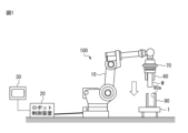
- FIG. 1 is a diagram showing a device configuration of a robot system according to a first embodiment.
- FIG. 2 is a functional block diagram of the robot system.
- FIG. 13 is a diagram showing a device configuration of a robot system according to a second embodiment.
- FIG. 13 is a diagram showing a device configuration of a robot system according to a third embodiment.
- FIG. 13 is a diagram showing a device configuration of a robot system according to a fourth embodiment.
- FIG. 13 is a diagram showing a device configuration of a robot system according to a fifth embodiment.
- FIG. 13 is a diagram showing a device configuration of a robot system according to a sixth embodiment.
- FIG. 13 is a diagram showing a device configuration of a robot system according to a first embodiment.
- FIG. 2 is a functional block diagram of the robot system.
- FIG. 13 is a diagram showing a device configuration of a robot system according to a second embodiment.
- FIG. 13 is a diagram showing a device configuration of
- FIG. 13 is a diagram showing a device configuration of a robot system according to a sixth embodiment, in which the robot posture is different from that of FIG. 7A.
- FIG. 23 is a diagram showing a device configuration of a robot system according to a seventh embodiment.
- FIG. 13 is a diagram showing the device configuration of a robot system according to a seventh embodiment, in which the robot posture is different from that of FIG. 8A.
- FIG. 23 is a diagram showing a device configuration of a robot system according to an eighth embodiment.
- FIG. 13 is a diagram showing a device configuration of a robot system according to an eighth embodiment, in which the robot posture is different from that of FIG. 7A.
- FIG. 13 is a diagram showing a device configuration of a robot system according to a ninth embodiment.
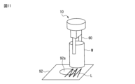
- FIG. 23 is a diagram for explaining a search operation in the ninth embodiment;
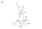
- FIG. 23 is a diagram showing the device configuration of a robot system according to a tenth embodiment.
- FIG. 23 is a diagram for explaining a phase search in the tenth embodiment.
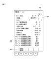
- FIG. 11 is a diagram showing an example of a setting screen in the first embodiment.
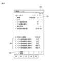
- FIG. 13 is a diagram showing an example of a setting screen in the fifth embodiment.
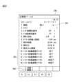
- FIG. 11 is a diagram showing an example of a setting screen in the second embodiment.
- FIG. 23 is a diagram showing an example of a setting screen in the sixth embodiment.
- FIG. 13 is a diagram showing an example of a setting screen in the third embodiment.
- FIG. 23 is a diagram showing an example of a setting screen in the seventh embodiment.
- FIG. 23 is a diagram showing the device configuration of a robot system according to a tenth embodiment.
- FIG. 23 is a diagram for explaining a phase search in the tenth embodiment.
- FIG. 11 is
- FIG. 13 is a diagram showing an example of a setting screen in the fourth embodiment.
- FIG. 23 is a diagram showing an example of a setting screen in the eighth embodiment.
- FIG. 13 is a diagram showing an example of a setting screen configured so that an operating area of the robot can be set.
- FIG. 2 shows the robot in a fully extended position.
- FIG. 13 is a diagram showing an example of a display screen that displays adjustment values obtained as a result of parameter adjustment.
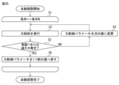
- 1 is a flowchart showing automatic parameter adjustment.
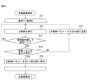
- 11 is a flowchart showing automatic parameter adjustment in a search operation.
- FIG. 1 is a diagram showing the equipment configuration of a robot system 100 according to an embodiment.
- the robot system 100 includes a robot 10, a robot control device 20 that controls the robot 10, and a teaching device 30 connected to the robot control device 20.
- Various types of end effectors can be attached to the robot 10 depending on the work application.
- FIG. 1 shows a configuration in which a hand 60 is attached to the tip of the arm of the robot 10 as an end effector.
- a force sensor (force detector) 70 is attached between the tip of the arm of the robot 10 and the hand 60.
- the robot system 100 can cause the robot 10 to perform force control based on the detection value detected by the force sensor 70.
- the robot 10 can be made to perform various types of work by introducing a necessary operation program according to the work content to be performed by the robot 10 (i.e., the application to be applied to the robot 10) and mounting the necessary end effector on the robot 10.
- FIG. 1 shows, as an example, a situation in which the robot 10 performs a precision fitting operation in which a cylindrical workpiece W held by the hand 60 is fitted into a fitting hole 90a of a workpiece 90 on the workbench 1.
- the robot system 100 is configured to automatically adjust parameters related to force control by having the robot 10 perform a force-controlled operation under conditions related to the work content.
- the robot 10 is a six-axis vertical articulated robot.
- various types of robots may be used as the robot 10 depending on the work target, such as a horizontal articulated robot, a parallel link type robot, or a dual-arm robot.
- the robot control device 20 controls the operation of the robot 10 according to an operation program or commands from the teaching device 30.
- the robot control device 20 may have a hardware configuration as a general computer having a processor 21 (see FIG. 2), memory (ROM, RAM, non-volatile memory, etc.), a storage device 129, an operation unit, an input/output interface, a network interface, etc.
- the teaching device 30 is used as an operation terminal for teaching the robot 10 and performing various settings.
- a teaching device configured with an information processing device such as a teaching operation panel or a tablet terminal can be used.
- the teaching device 30 may have a hardware configuration as a general computer having a processor, memory (ROM, RAM, non-volatile memory, etc.), a storage device, an operation unit, a display unit 31 (see Figure 2), an input/output interface, a network interface, etc.
- the display unit 31 is, for example, a liquid crystal display.
- the operation unit may be a touch panel type input device integrated with the display unit 31.
- the force sensor 70 is, for example, a six-axis force sensor that detects forces acting in the mutually orthogonal X, Y, and Z axis directions, and moments around each axis.
- the force sensor 70 detects external forces acting on the robot 10, but it may also be configured to determine the external forces acting on a specific part of the robot based on the detection values of torque sensors placed on each axis of the robot and the robot's posture information. Alternatively, it may be configured to determine the load torque of each axis by measuring the drive current of the motors 111 (see Figure 2) placed on each axis of the robot 10, and to determine the external force acting on a specific part of the robot 10 based on this information and the robot's posture information.
- FIG. 2 is a functional block diagram of the robot system 100.
- the robot control device 20 includes a motion control unit 121, a force control unit 122, a force data processing unit 123, a parameter adjustment unit 124, and a setting unit 126. These functional blocks may be functional elements that are realized by the processor 21 of the robot control device 20 executing a program.
- the robot control device 20 includes a storage device 129.
- the storage device 129 is, for example, a storage device formed of a non-volatile memory or a hard disk device.
- the storage device 129 stores operation programs for controlling the robot 10, force control parameters, various setting information, and the like.
- the operation control unit 121 controls the operation of the robot 10 according to an operation program or according to commands from the teaching device 30.
- the robot control device 20 is equipped with a servo control unit (not shown) that performs servo control on the motors 111 of each axis according to commands for each axis generated by the operation control unit 121.
- the force data processing unit 123 provides a function for calculating the external force (force and moment) acting on the robot 10 (hand 60) based on the detection value of the force sensor 70.
- the position and orientation of the force sensor 70 can be calculated from the position and orientation of the coordinate system of the wrist tip of the robot 10 and the relative position information of the force sensor 70 with respect to the wrist tip.
- the force data processing unit 123 can calculate the magnitude and direction of the force or moment in a preset arbitrary coordinate system based on the position, orientation, and detection value of the force sensor 70.
- the force control unit 122 is responsible for the function of executing force control based on the force information calculated by the force data processing unit 123 and predetermined force control parameters.
- the movement control unit 121 has a function of causing the robot 10 to execute movements based on force control under the control of the force control unit 122.
- the parameter adjustment unit 124 has a function of adjusting the force control parameters by having the robot 10 execute a specified task.
- the parameter adjustment unit 124 according to this embodiment is configured to adjust the force control parameters by having the robot 10 execute a force-controlled operation based on conditions related to the content of the task to be executed by the robot 10.
- the parameter adjustment unit 124 may include a determination unit 125 that can determine whether the force control parameters being applied are appropriate in the parameter adjustment process.
- the setting unit 126 can provide a function for accepting settings of various parameters related to force control parameters and parameter adjustment processing.
- the setting unit 126 can provide a user interface for accepting various settings on the display unit 31 of the teaching device 30.
- the first embodiment is an example of the parameter adjustment process in which the work to be performed by the robot 10 is precision fitting (fitting operation) and the condition related to the work is the type of workpieces (number of workpieces) to be worked on.
- the configuration of the robot system 100 is as shown in FIG.
- the following force control parameters are subject to adjustment.
- Pressing force (2) Fitting speed (3) Force control gain
- the pressing force is a target force in the direction in which the workpiece W is inserted into the fitting hole 90a of the fitted workpiece 90, as shown by the arrow in FIG. 1.
- the fitting speed is the speed at which the workpiece W is moved along the pressing direction (the direction of the arrow in FIG. 1).
- the force control gain is multiplied by the deviation between the target force (force or moment) and the actual detected force (force or moment) to bring the actual detected force closer to the target force. If the force control gain is relatively large, the response speed of the force control becomes faster, but the response tends to become unstable. If the force control gain is relatively small, the operation of the force control becomes stable, but the required time tends to increase. In the parameter adjustment process, these parameters are automatically adjusted to appropriate values.
- the force control gain related to the pressing force in the pressing direction may be the subject of parameter adjustment as the force control gain.
- the force control gain for five components namely the force in the pressing direction (this is the Z direction), the force in the X-axis direction, the force in the Y-axis direction, the moment about the X-axis, and the moment about the Y-axis, may be the subject of parameter adjustment processing.
- the set forces (target forces) for the force in the X-axis direction, the force in the Y-axis direction, the moment about the X-axis, and the moment about the Y-axis in the force control may be set to zero, for example.
- the user specifies the type (number of workpieces) of workpieces W to be applied to the parameter adjustment process.
- the setting unit 126 provides a function for accepting the user's specification of the type (number of workpieces).
- the parameter adjustment unit 124 searches for appropriate parameter values by performing a precision fitting operation for each of the specified workpieces W. Since each workpiece W includes individual differences, the size of the gap between the inner surface of the fitting hole 90a varies depending on the workpiece, and the force control parameters to be applied also vary. Therefore, by performing force control operations on multiple workpieces to search for appropriate parameter values, appropriate parameter values that take into account the individual differences of the workpieces can be obtained.
- FIG. 25 shows a flowchart for realizing automatic parameter adjustment in the configuration of this embodiment. This process is executed under the control of the processor 21 of the robot control device 20. Note that the parameter adjustment process shown in FIG. 25 is also applicable to the configurations of the second to eighth embodiments described below.
- step S1 the initial values of the force control parameters are set.
- This process is performed by looping a series of steps S2 to S5 for multiple conditions related to the work content of the robot (step S1).
- the type of work (number of workpieces) is defined as conditions 1 to N.
- parameter adjustment is performed for N workpieces.
- step S2 work is performed using force control according to the current conditions and force control parameters.
- the work performed here is precision fitting in the configuration of the first embodiment.
- the determination unit 125 checks the response of the actual detected force to the set force (target force) while force control is being executed to check whether a situation has arisen in which the robot oscillates or the detected force value becomes excessive (step S3). For example, if the adjustment is to be made on the force control gain of the pressing force, the determination unit 125 obtains the actual detected value of the pressing force as the response to the force control from the output of the force sensor 70. By checking the response waveform of this actual detected value, the determination unit 125 detects whether the robot's operation has become unstable due to the force control response oscillating or becoming excessive.
- the parameter adjustment unit 124 updates the force control parameter to the next value (step S4). If the force control response is oscillating or excessive (S3: YES), the current force control parameter is not appropriate, so the parameter adjustment unit 124 returns the force control parameter to the previous value (step S5).
- step S2 If there are any unprocessed conditions, the process is executed from step S2 for the next condition (here, the next work).
- step S5 When the loop process of steps S2 to S5 has been completed for all conditions (here, all works), this parameter adjustment process ends.
- the above process allows appropriate parameter values to be obtained for each of the multiple workpieces. Once parameter values have been obtained for the multiple workpieces in this way, those that can maintain normal force control operation for all of the workpieces (for example, the smallest values for force control gain and engagement speed) can be adopted as parameter adjustment values.
- the above parameter adjustment process allows the force control parameters to be adjusted based on the condition that, of the multiple conditions related to the work content, causes the detection value of the force sensor 70 to be the most oscillatory (or the most excessive). Therefore, the above parameter process allows for the acquisition of parameter values that are appropriate for all specified conditions (here, all specified workpieces).
- the initial value and the direction of the search when searching for parameters may be set appropriately according to the properties of the target parameter. For example, for pressing force, engagement speed, and force control gain, the larger the value, the faster the response can be, but the more likely the response is to become unstable. From this perspective, the search may start from low values for these parameters, and a search may be performed so that the highest value at the limit where the response does not become unstable can be obtained as the adjustment value.
- Such parameter adjustment can be achieved by the processing flow shown in FIG. 25.
- the parameter values to be used for automatic adjustment may be set in a table in advance, and parameter values may be selected in order from this table to perform parameter search.
- a table of parameter values such as the following may be prepared in advance for the pressing force, fitting speed, and force control gain.
- i ranges from 1 to 5.
- P(1), V(1), and G(1) may be used as initial values, and if there is no problem with force control (S3: NO), the parameter values may be increased by one step to use P(2), V(2), and G(2), and if there is a problem with force control with P(2), V(2), and G(2) (S3: YES), the parameter values may be decreased by one step to P(1), V(1), and G(1).
- the initial values for the parameter search, the direction of change, and the upper limit (or lower limit) can be set arbitrarily.
- the following parameter adjustment may be performed from another perspective.
- the pressing force it may be desirable to keep the pressing force as low as possible from the perspective of protecting the workpiece (preventing damage to the workpiece).
- Step a1 setting an initial value of a pressing force that is so low that an appropriate mating operation (e.g., a target mating speed) cannot be achieved;
- Step a2) Execute force control;
- Step a3) Gradually increase the pressing force,
- Step a4) Obtaining, as an adjustment value, the pressing force at the time when an appropriate fitting operation (e.g., a target fitting speed) is achieved; You can also take this search method.
- step S4 When changing parameter values in step S4 in the processing flow of FIG. 25, multiple force control parameters to be adjusted may be changed simultaneously, or only one force control parameter may be changed in step S4. When only one force control parameter is changed in step S4, the processing flow of FIG. 25 may be executed separately for each of the multiple force control parameters to be adjusted.
- the initial parameter value at the start of the search is the same value.
- an operation example may be possible in which the search for parameters for the next workpiece is started from the adjustment value for the previous workpiece.
- the adjustment target is a force control gain or a fitting speed, and it is desired to adjust the value to the highest possible value without exceeding a limit value.
- Step b1 For the first workpiece, a parameter search is performed in which the parameter value is gradually increased from a low initial value and a higher value is searched for up to the limit.
- Step b2) The parameter adjustment values for the first work are recorded.
- Step b3) For the next workpiece, a search is started using the parameter adjustment values for the previous workpiece as initial values. First, it is determined whether force control operation is possible with these parameter initial values. (Step b4) If it is determined in step b3 that the device is operable, a parameter search is performed to gradually increase the parameter value and search for a higher value up to the limit. The adjustment value obtained in this search is recorded.
- Step b5 If it is determined in step b3 that the operation is impossible, a search operation is performed to gradually decrease the parameter value and search for a parameter value that can successfully control the force. The parameter value when successful is recorded as the adjustment value.
- Step b6 For the third and subsequent workpieces, the same processing as steps b3 to b5 is performed. By the above processing, it is possible to obtain parameter adjustment values that enable the force control operation to be performed appropriately for all workpieces and that satisfy the condition of setting the highest possible value.
- the parameter adjustment process described above can also be used in cases where a workpiece is added as an adjustment target at a later stage.
- the previously adjusted adjustment values can be used as the initial values for the parameter search, and a parameter search such as steps b3 to b5 described above can be performed.
- the second embodiment is an example of the parameter adjustment process in which the work to be performed by the robot 10 is constant force pressing, and the multiple conditions related to the work are the types of workpieces (number of workpieces) to be worked on.
- the configuration of the robot system 100 in this embodiment is shown in FIG.
- the robot 10 presses the workpiece W held by the hand 60 against an object with a constant force.
- the robot 10 presses the tip of the workpiece W against the top surface of the workbench 1.
- Actual work involving constant force pressing can be, for example, the robot pressing a button, the robot pressing a tool against an object, etc.
- Pushing force (2) Force control gain (pushing direction)
- the pressing direction is a direction perpendicular to the upper surface of the worktable 1A as shown by the arrow in Fig. 3.
- the force control gain is adjusted in the pressing direction.
- the user specifies the type of workpiece W (number of workpieces) to be applied to the parameter adjustment process.
- the parameter adjustment unit 124 searches for appropriate parameter values by performing a constant force pressing operation on each of the specified number of workpieces W.
- Each workpiece W includes individual differences. Therefore, by performing force-controlled work on multiple workpieces to search for appropriate parameter values, it is possible to obtain appropriate parameter values that take into account the individual differences of the workpieces.
- the initial values, search direction, and processing flow of the parameter search can be the same as those described above for the first embodiment.
- the parameter adjustment process of FIG. 25, the parameter adjustment method according to steps a1 to a4, and the parameter adjustment method according to steps b1 to b6 can be applied to the present embodiment as well.
- the third embodiment is an example of parameter processing in which the work to be performed by the robot 10 is surface matching, and the multiple conditions related to the work are the types of workpieces (number of workpieces) to be worked on.
- the configuration of the robot system 100 in this embodiment is shown in FIG.
- Face matching is the process of matching the leading edge of the workpiece W with the target for face matching (the top surface of the worktable 1B in FIG. 3).
- the robot 10 presses the workpiece W with a constant pressing force in the pressing direction indicated by the arrow in the figure, and performs face matching while also adjusting the posture of the workpiece W.
- Pushing force (2) Force control gain (pushing direction, around X-axis, around Y-axis)
- the pressing direction is a direction perpendicular to the top surface of the worktable 1B as shown by the arrow in Fig. 4.
- the force control gain three components, namely, the target force (pressing force) in the pressing direction (this is the Z direction), the moment about the X axis, and the moment about the Y axis, may be subject to parameter adjustment processing.
- the set forces (target forces) of the moment about the X axis and the moment about the Y axis in the force control may be set to zero, for example.
- the user specifies the number of workpieces to be applied to the parameter adjustment process.
- the parameter adjustment unit 124 searches for appropriate parameter values by performing a surface alignment operation for each of the specified number of workpieces W.
- Each workpiece W includes individual differences. Therefore, by performing a force-controlled operation on multiple workpieces to search for appropriate parameter values, it is possible to obtain appropriate parameter values that take into account the individual differences of the workpieces.
- the initial values, search direction, and processing flow of the parameter search can be the same as those described above for the first embodiment.
- the parameter adjustment process of FIG. 25, the parameter adjustment method according to steps a1 to a4, and the parameter adjustment method according to steps b1 to b6 can be applied to the present embodiment as well.
- the fourth embodiment is an example of the parameter adjustment process in which the work to be performed by the robot is deburring, and the multiple conditions related to the work are the types of workpieces (number of workpieces) to be worked on.
- the configuration of the robot system 100 in this embodiment is shown in FIG.
- the robot 10 is equipped with a deburring tool (grinder, etc.) 60A as an end effector.
- a deburring tool grinding, etc.
- the robot 10 executes an operation of moving the deburring tool 60A, for example, by tracing the edge of the workpiece 91 to be deburred. This removes burrs present on the workpiece 91 to be deburred.
- deburring can be considered a tracing operation in which the robot operates by tracing the external shape of the workpiece.
- Pushing force (2) Force control gain (pushing direction)
- the pressing direction in this embodiment is, for example, the direction (horizontal direction) in which the deburring tool 60A is pressed against the workpiece 91 on the workbench 1C as shown by the arrow in Fig. 5.
- the force control gain is adjusted in the pressing direction.
- the user specifies the number of workpieces to be applied to the parameter adjustment process.
- the parameter adjustment unit 124 searches for appropriate parameter values by performing a deburring operation on each of the specified number of workpieces 91.
- Each of the workpieces 91 includes individual differences. Therefore, by performing a force-controlled operation on multiple workpieces to search for appropriate parameter values, it is possible to obtain appropriate parameter values that take into account the individual differences of the workpieces.
- the fifth embodiment is an example of the parameter adjustment process in which the work content to be executed by the robot 10 is precision fitting, and the multiple conditions related to the work content are multiple postures of the robot 10.
- the configuration of the robot system 100 in this case is shown in FIG.
- the user specifies multiple postures that the robot 10 should take during operation.
- the multiple postures of the robot may be specified as the mating points of four mating objects W1 to W4 located at different locations.
- the workpieces W1 to W4 are at different distances from the robot 10.
- the robot 10 since the workpiece W1 is close to the robot 10, the robot 10 takes a contracted posture when the robot 10 works on the workpiece W1.
- the robot 10 since the workpiece W4 is located relatively far from the robot 10, the robot 10 takes a fully extended posture when the robot 10 works on the workpiece W4. Therefore, the postures of the robot 10 when performing precision mating for these workpieces W1 to W4 are different.
- the parameter adjustment unit 124 adjusts the parameters by performing a precision fitting operation in each of a number of robot postures. In this way, by searching for appropriate parameters while performing tasks in different robot postures, appropriate parameters that can be applied to any posture of the robot 10 can be obtained.
- the initial values, search direction, and processing flow of the parameter search can be the same as those described above for the first embodiment.
- the parameter adjustment process of FIG. 25, the parameter adjustment method according to steps a1 to a4, and the parameter adjustment method according to steps b1 to b6 can be applied to the present embodiment as well.
- the sixth embodiment is an example of the parameter adjustment process in which the work content to be executed by the robot is pressing with a constant force, and the multiple conditions related to the work content are multiple postures of the robot 10.
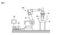
- An example of the configuration of the robot system 100 in this case is shown in Figures 7A and 7B.
- the user specifies multiple postures that the robot 10 should take while working.
- Multiple pressing points with different positions relative to the robot 10 may be specified as the multiple postures that the robot 10 should take.
- a position relatively close to the robot 10 is specified as the pressing point, as shown in FIG. 7A
- a position relatively far from the robot 10 is specified as the pressing point, as shown in FIG. 7B.
- FIG. 7A the robot 10 is in a contracted posture
- FIG. 7B the robot 10 is in an extended posture.
- the parameter adjustment unit 124 adjusts the parameters by performing a pressing operation in each of a number of robot postures. In this way, by searching for appropriate parameters while performing tasks in different robot postures, it is possible to obtain appropriate parameters that can be applied to any posture of the robot 10.
- the initial values, search direction, and processing flow of the parameter search can be the same as those described above for the first embodiment.
- the parameter adjustment process of FIG. 25, the parameter adjustment method according to steps a1 to a4, and the parameter adjustment method according to steps b1 to b6 can be applied to the present embodiment as well.
- the seventh embodiment is an example of the parameter adjustment process in which the work content to be executed by the robot is surface matching, and the multiple conditions related to the work content are multiple postures of the robot 10.
- An example of the configuration of the robot system 100 in this case is shown in Figures 8A and 8B.
- Pushing force (2) Force control gain (pushing direction, around X-axis, around Y-axis)
- the user specifies multiple postures that the robot 10 should take during work.
- Multiple pressing points (surface matching points) with different positions relative to the robot 10 may be specified as multiple postures that the robot 10 should take.
- a position relatively close to the robot 10 is specified as the pressing point (surface matching point), as shown in FIG. 8A
- an example is shown in which a position relatively far from the robot 10 is specified as the pressing point (surface matching point), as shown in FIG. 8B.
- the robot 10 is in a contracted posture
- FIG. 8B the robot 10 is in an extended posture.
- the parameter adjustment unit 124 adjusts the parameters by performing a surface alignment operation in each of a number of robot postures. In this way, by searching for appropriate parameters while performing tasks in different robot postures, appropriate parameters that can be applied to any posture of the robot 10 can be obtained.
- the initial values, search direction, and processing flow of the parameter search can be the same as those described above for the first embodiment.
- the parameter adjustment process of FIG. 25, the parameter adjustment method according to steps a1 to a4, and the parameter adjustment method according to steps b1 to b6 can be applied to the present embodiment as well.
- Eighth Example The eighth embodiment is an example of the parameter adjustment process in which the work content to be executed by the robot is deburring, and the multiple conditions related to the work content are multiple postures of the robot 10.
- An example of the configuration of the robot system 100 in this case is shown in Figures 9A and 9B.
- the user specifies a number of postures that the robot 10 should take during the task.
- the user specifies multiple postures that the robot 10 should take during work.
- multiple pressing points (deburring points) with different positions relative to the robot 10 may be specified.
- a position relatively close to the robot 10 is specified as the pressing point (deburring point), as shown in Fig. 9A
- a position relatively far from the robot 10 is specified as the pressing point (deburring point)
- Fig. 9B In the case of Fig. 9A, the robot 10 is in a contracted posture, and in the case of Fig. 9B, the robot 10 is in an extended posture.
- the parameter adjustment unit 124 adjusts the parameters by performing the deburring operation in each of the multiple robot postures. In this way, by searching for appropriate parameters while performing the work in different robot postures, appropriate parameters that can be applied to any posture of the robot 10 can be obtained.
- the initial values, search direction, and processing flow of the parameter search can be the same as those described above for the first embodiment.
- the parameter adjustment process of FIG. 25, the parameter adjustment method according to steps a1 to a4, and the parameter adjustment method according to steps b1 to b6 can be applied to the present embodiment as well.
- the force control parameters can be adjusted based on the condition in which the detection value of the force sensor 70 is the most oscillatory (or the most excessive) among multiple conditions related to the work content. Therefore, it is possible to obtain force control parameters that can stably execute force control under any of multiple conditions.
- the ninth embodiment is an example in which the work to be performed by the robot is a search operation. That is, in this embodiment, the condition related to the work content is that the work content is a search operation.
- the configuration of the robot system 100 in this embodiment is shown in FIG. 10.
- the search operation is an operation in which a cylindrical workpiece W held by the robot 10 is moved on a fitted workpiece 92 to search for a hole 92a into which the workpiece W should be fitted.
- the hole 92a of the fitted workpiece 92 is searched for by moving the workpiece W along a predetermined trajectory L.
- the parameter adjustment unit 124 determines the following parameters to be adjusted. (1) Pressing force (2) Searching motion speed (speed in the search direction)
- FIG. 26 shows a flowchart of the parameter adjustment process executed under the control of the parameter adjustment unit 124 (processor 21) when the work content is an exploration operation.
- FIG. 26 shows an example of a case where parameter adjustment is executed for multiple conditions (conditions 1 to N).
- the multiple conditions are the type of workpiece (number of workpieces) or multiple postures of the robot.
- step S12 work (search operation) is performed using force control according to the current conditions and force control parameters.
- the parameter adjustment unit 124 checks whether the search has been successful without a search operation (step S13). Whether or not a search operation has been performed may be determined based on whether the robot 10 has actually performed a zigzag movement of a certain distance or more. If the search has been successful without a search operation (S13: YES), the process returns to step S12. In this case, an operation of positioning the fitting workpiece W relative to the fitted workpiece 92 is performed again, and a search operation using force control is performed again (step S12).
- the determination unit 125 checks whether a situation has arisen in which the robot oscillates or the detected force value becomes excessive by checking the response of the actual detected force to the set force (target force) while force control is being executed (step S14). For example, the determination unit 125 obtains the actual detected value of the pressing force as a response to force control from the output of the force sensor 70. By checking the response waveform of this actual detected value, the determination unit 125 detects whether the robot's operation has become unstable due to oscillation or excessive response to force control.
- the parameter adjustment unit 124 sets the next set of parameter values from a pre-prepared table as the force control parameters (step S15). If the force control response is oscillating or excessive (S14: YES), the current set of parameter values is not appropriate, so the parameter adjustment unit 124 returns the set of parameter values to the previous value (step S16).
- step S12 If there are any unprocessed conditions, the process from step S12 is executed for the next condition.
- this parameter adjustment process ends. Through the above process, appropriate parameter values (pressing force, search speed) are obtained for multiple conditions.
- the parameter adjustment unit 124 performs parameter adjustment specific to a search operation in accordance with the condition that the work content is a search operation, and can obtain appropriate parameter values. Furthermore, when the work content is a search operation, the parameter adjustment unit 124 performs parameter adjustment processing for multiple conditions (type of workpiece (number of workpieces) or different postures of the robot), and can obtain force control parameters that allow the search operation to be performed stably even if the posture of the workpiece or robot changes.
- the tenth embodiment is an example in which the work to be executed by the robot is phase search.
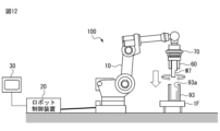
- a configuration example of the robot system 100 in this case is shown in Fig. 12.
- a detailed operation example of the phase search is shown in Fig. 13.
- the fitting workpiece W7 is rotated to align the phase so that the rotational position (phase) of the pin 7a of the fitting workpiece W7 matches the rotational position (phase) of the key groove 93b formed in the hole 93a of the fitted workpiece 93.
- the parameter adjustment unit 124 adjusts the following parameters. (1) Pressing force (2) Searching speed (speed in the direction in which the fitting workpiece is rotated)
- step S13 the determination of whether or not a search operation (phase search) has been performed (step S13) is performed as follows: Whether or not the robot 10 has actually rotated the fitting workpiece W7 by a certain rotation angle or more, or The determination may be made based on whether or not the robot 10 has caused the workpiece W7 to reciprocate in the rotation direction.
- the parameter adjustment unit 124 performs parameter adjustment specific to movement search in accordance with the condition that the work content is phase search, and can obtain appropriate parameter values. Furthermore, when the work content is phase search, the parameter adjustment unit 124 performs parameter adjustment processing for multiple conditions (type of workpiece (number of workpieces) or different postures of the robot), and can obtain force control parameters that can stably execute a search operation even if the posture of the workpiece or robot changes.
- FIG. 14 shows a setting screen (user interface) 210 provided by the setting unit 126 in the configuration of the first embodiment described above. That is, the setting screen 210 is a setting screen when the work content is precision fitting and the multiple conditions related to the work content are the type of workpieces (number of workpieces).
- This setting screen 210 (and similar setting screens described below) is displayed, for example, on the display screen of the display unit 31 of the teaching device 30. The user can input various parameters to this setting screen 210 via the operation unit of the teaching device 30.
- the setting screen 210 includes a display field 211 for displaying or specifying the work content.
- the setting screen 210 includes, as parameters related to the fitting operation, the specification of the coordinate system, the insertion direction for inserting the workpiece, the fitting depth, the upper limit of the generated force, etc. If an upper limit of the generated force is specified, the parameter adjustment unit 124 performs adjustment within a range in which the pressing force does not exceed this upper limit, for example.
- the setting screen 210 further includes a specification field 212 for specifying the type of workpiece (number of workpieces) to be used in the work as a number of conditions related to the work content.
- the user performs the following operations on the setting screen 200.
- the user inputs parameters such as the designation of the coordinate system, the insertion direction for inserting the workpiece, the fitting depth, and the upper limit of the generated force, or confirms and adjusts the default values previously set for these.
- the user inputs only the number of workpieces required in the designation field 212.
- the user selects one or more workpieces from the designation field 212 and operates the button 215 (F2 key) that executes automatic adjustment, thereby executing the parameter adjustment process for the selected workpieces.
- the user repeats this operation to execute parameter adjustment for all workpieces specified in the designation field 212.
- the parameter adjustment unit 124 obtains parameter values that allow stable operation for all workpieces through the above-mentioned parameter adjustment process.
- FIG. 15 shows a setting screen 250 provided by the setting unit 126 in the configuration of the fifth embodiment described above.
- the setting screen 250 is a setting screen when the work content is precision fitting and the multiple conditions related to the work content are multiple postures of the robot.
- the setting screen 250 accepts input of various parameters related to the work content.
- the setting screen 250 includes a display field 251 for displaying or specifying the work content.
- the setting screen 250 includes parameters related to the fitting operation, such as specification of a coordinate system, the insertion direction for inserting the workpiece, the fitting depth, and the upper limit of the generated force.
- the setting screen 250 further includes a specification field 252 for specifying multiple postures of the robot as multiple conditions related to the work content.
- a precision fitting operation is performed for the multiple robot postures specified here, and the parameters are adjusted.
- the user inputs the required number of robot postures in the specification field 252.
- the user selects one or more robot postures from the specification field 252 and operates the button 255 (F2 key) that executes automatic adjustment, thereby executing a parameter adjustment process for the selected robot postures.
- the user repeats this operation to execute parameter adjustment for all robot postures specified in the specification field 252.
- the parameter adjustment unit 124 obtains parameter values that enable stable operation for all workpieces through the above-mentioned parameter adjustment process.
- FIG. 16 shows the setting screen 220 provided by the setting unit 126 in the configuration of the second embodiment described above.
- the setting screen 220 is a setting screen when the work content is constant force pressing, and the multiple conditions related to the work content are the type of work (number of work).
- the setting screen 220 accepts input of various parameters related to the work content.
- the setting screen 220 includes a display field 221 for displaying or specifying the work content.
- the setting screen 220 includes parameters related to constant force pressing, such as designation of the coordinate system, pressing direction in which the workpiece is pressed, pressing time, pressing force, and upper limit of generated force.
- the setting screen 220 further includes a designation field 222 for designating the type of workpiece (number of workpieces) to be used in the work.
- a constant force pressing operation is performed on the number of workpieces designated here, and the parameters are adjusted.
- the user inputs the number of workpieces required in the specification field 222.
- the user selects one or more workpieces from the specification field 222 and operates the button 225 (F2 key) that executes automatic adjustment, thereby executing the parameter adjustment process for the selected workpieces.
- the user repeats this operation to execute parameter adjustment for all the workpieces specified in the specification field 222.
- the parameter adjustment unit 124 obtains parameter values that allow stable operation for all the workpieces through the above-mentioned parameter adjustment process.
- FIG. 17 shows a setting screen 260 provided by the setting unit 126 in the configuration of the sixth embodiment described above.
- the setting screen 260 is a setting screen when the work content is constant force pressing, and the multiple conditions related to the work content are multiple postures of the robot.
- the setting screen 260 accepts input of various parameters related to the work content.
- the setting screen 260 includes a display field 261 for displaying or specifying the work content.
- the setting screen 260 includes, as parameters related to constant force pressing, the specification of the coordinate system, the pressing direction in which the workpiece is pressed, the pressing time, the pressing force, and the upper limit of the generated force.
- the setting screen 260 further includes a specification field 262 for specifying multiple postures of the robot as multiple conditions related to the work content.
- a precision fitting operation is performed for the multiple robot postures specified here, and the parameters are adjusted.
- the user inputs the required number of robot postures in the specification field 262.
- the user selects one or more robot postures from the specification field 262 and operates the button 265 (F2 key) to execute automatic adjustment, thereby executing a parameter adjustment process for the selected robot postures.
- the user repeats this operation to execute parameter adjustment for all robot postures specified in the specification field 262.
- the parameter adjustment unit 124 obtains parameter values that enable stable operation for all workpieces through the above-mentioned parameter adjustment process.
- FIG. 18 shows a setting screen 230 provided by the setting unit 126 in the configuration of the third embodiment described above.
- the setting screen 230 is a setting screen when the work content is surface alignment and the multiple conditions related to the work content are the type of work (number of work).
- the setting screen 230 accepts input of various parameters related to the work content.
- the setting screen 230 includes a display field 231 for displaying or specifying the work content.
- the setting screen 230 includes parameters related to surface matching, such as specification of a coordinate system, the pressing direction in which the workpiece is pressed, pressing time, pressing force, and the upper limit of the generated force.
- the setting screen 230 further includes a specification field 232 for specifying the type of workpiece (number of workpieces) to be used in the work.
- a specification field 232 for specifying the type of workpiece (number of workpieces) to be used in the work.
- an example is shown in which five workpieces are specified as the workpieces to be used in the work, but it is also possible to specify other numbers of workpieces.
- a constant force pressing operation is performed on the number of workpieces specified here, and the parameters are adjusted.
- the user inputs the number of workpieces required in the specification field 232.
- the user selects one or more workpieces from the specification field 232 and operates the button 235 (F2 key) that executes automatic adjustment, thereby executing the parameter adjustment process for the selected workpieces.
- the user repeats this operation to execute parameter adjustment for all the workpieces specified in the specification field 232.
- the parameter adjustment unit 124 obtains parameter values that allow stable operation for all the workpieces through the above-mentioned parameter adjustment process.
- FIG. 19 shows a setting screen 270 provided by the setting unit 126 in the configuration of the seventh embodiment described above.
- the setting screen 270 is a setting screen when the work content is surface matching and the multiple conditions related to the work content are multiple postures of the robot.
- the setting screen 270 accepts input of various parameters related to the work content.
- the setting screen 270 includes a display field 271 for displaying or specifying the work content.
- the setting screen 270 includes parameters related to surface matching, such as specification of a coordinate system, the pressing direction in which the workpiece is pressed, pressing time, pressing force, and the upper limit of the generated force.
- the setting screen 260 further includes a specification field 272 for specifying multiple postures of the robot as multiple conditions related to the work content.
- a specification field 272 for specifying multiple postures of the robot as multiple conditions related to the work content.
- an example is shown in which five robot postures are specified as the multiple robot postures, but it is also possible to specify other numbers of robot postures.
- a precision fitting operation is performed for the multiple robot postures specified here, and the parameters are adjusted.
- the user inputs the required number of robot postures in the specification field 272.
- the user selects one or more robot postures from the specification field 272 and operates the button 275 (F2 key) to execute automatic adjustment, thereby executing parameter adjustment processing for the selected robot postures.
- the user repeats this operation to execute parameter adjustment for all robot postures specified in the specification field 272.
- the parameter adjustment unit 124 obtains parameter values that enable stable operation for all workpieces through the above-mentioned parameter adjustment processing.
- FIG. 20 shows a setting screen 240 provided by the setting unit 126 in the configuration of the fourth embodiment described above.
- the setting screen 240 is a setting screen when the work content is deburring (copying operation) and the multiple conditions related to the work content are the type of work (number of work).
- the setting screen 240 accepts input of various parameters related to the work content.
- the setting screen 240 includes a display field 241 for displaying or specifying the work content.
- the setting screen 240 includes parameters related to deburring, such as coordinate system specification, pressing direction, pressing time, pressing force, and upper limit of generated force.
- the setting screen 240 further includes a specification field 242 for specifying the type of work (number of work) to be used in the work.
- a specification field 242 for specifying the type of work (number of work) to be used in the work.
- an example is shown in which five workpieces are specified as the workpieces to be used in the work, but it is also possible to specify other numbers of workpieces.
- a constant force pressing operation is performed on the number of workpieces specified here, and the parameters are adjusted.
- the user inputs the number of workpieces required in the specification field 242.
- the user selects one or more workpieces from the specification field 242 and operates the button 245 (F2 key) that executes automatic adjustment, thereby executing the parameter adjustment process for the selected workpieces.
- the user repeats this operation to execute parameter adjustment for all the workpieces specified in the specification field 242.
- the parameter adjustment unit 124 obtains parameter values that allow stable operation for all the workpieces through the parameter adjustment process described above.
- FIG. 21 shows a setting screen 280 provided by the setting unit 126 in the configuration of the eighth embodiment described above.
- the setting screen 280 is a setting screen when the work content is deburring (copying operation) and the multiple conditions related to the work content are multiple postures of the robot.
- the setting screen 280 accepts input of various parameters related to the work content.
- the setting screen 280 includes a display field 281 for displaying or specifying the work content.
- the setting screen 280 includes parameters related to deburring, such as coordinate system specification, pressing direction, pressing time, pressing force, and upper limit of generated force.
- the setting screen 280 further includes a specification field 282 for specifying multiple postures of the robot as multiple conditions related to the work content.
- a specification field 282 for specifying multiple postures of the robot as multiple conditions related to the work content.
- five robot postures are specified as the multiple robot postures, but it is also possible to specify other numbers of robot postures.
- a precision fitting operation is performed for the multiple robot postures specified here, and the parameters are adjusted.
- the user inputs the required number of robot postures in the specification field 282.
- the user selects one or more robot postures from the specification field 282 and operates the button 285 (F2 key) that executes automatic adjustment, thereby executing a parameter adjustment process for the selected robot postures.
- the user repeats this operation to execute parameter adjustment for all robot postures specified in the specification field 282.
- the parameter adjustment unit 124 obtains parameter values that enable stable operation for all workpieces through the above-mentioned parameter adjustment process.
- the setting unit 126 may be configured to receive an input specifying an area in which the robot 10 operates as a condition related to the work content in the parameter adjustment process.
- the parameter adjustment unit 124 can operate the robot so that it performs work at one or more positions within this operating area. Specifying the operating area can be said to correspond to specifying one or more postures of the robot.
- FIG. 22 shows an example of a setting screen 290 configured to enable the operation area of the robot 10 to be set.
- a setting screen is shown that enables the robot operation area to be specified for the task of pressing a constant force.
- the setting screen 290 includes an input field 291 for specifying the operation area of the robot.
- the input field 291 has specification fields 292, 293 for specifying the positions of two opposing corners of a rectangular operation area.
- the parameter adjustment unit 124 sets multiple positions where the robot 10 should be located within the area specified here, and operates to perform a constant force pressing operation at each position.
- the method of setting the operating position (working location) of the robot from the operating area is as follows: (r1) Set the robot's position as widely as possible within its operating area; (r2) Within the motion area, include positions that result in a robot posture that is difficult to achieve force control performance, The following selection methods are possible.
- the former (r1) for example, when a rectangular operating area is specified, the positions of the four corners and the center of the rectangular area are selected.
- the latter method (r2) is used, for example, as shown in FIG. 23, a posture in which the robot 10 is fully stretched is included in the robot posture during parameter adjustment. In the posture in which the robot 10 is fully stretched as shown in FIG. 23, the rigidity of the robot 10 as a whole is reduced, resulting in a posture in which it is difficult to obtain force control performance. By including such a posture in the parameter adjustment, it becomes possible to obtain parameter values that enable more stable force control to be performed.
- the parameter adjustment unit 124 may further include a function for displaying parameter values obtained as adjustment results of the parameter adjustment process.
- FIG. 24 shows an example of a display screen 300 on which the parameter adjustment unit 124 displays adjustment values obtained as a result of parameter adjustment. This display screen 300 is displayed, for example, on the display unit 31 of the teaching device 30.
- the display screen 300 displays the parameter values of the approach speed, contact judgment threshold, and force control gain as a result of parameter adjustments made to a specific task.
- the parameter adjustment unit 124 may be configured to present multiple parameter set candidates thus obtained via the display screen 300, and to accept a user operation to select a parameter set to actually be applied from the parameter set candidates.
- the display screen 300 is configured to allow switching to other parameter candidate values by operating a switching button 301 (F4 key). The user can set the parameter set currently displayed on the display screen 300 as the parameter set to actually be applied.
- the robot control device applies an appropriate parameter adjustment process according to the type of work content as a condition related to the work content to be performed by the robot, and can obtain force control parameters that can perform stable force control according to the work content. Also, according to the above-mentioned embodiment, the robot control device can obtain force control parameters that can perform stable force control for multiple conditions by performing force control for multiple conditions related to the work content.
- the parameter adjustment unit 124 can adaptively switch and execute adjustment contents (processing contents, types of parameters to be adjusted, etc.) depending on whether the work content is precision fitting, constant force pressing, surface matching, deburring, or search operation.
- the functional blocks shown in Figure 2 may be realized by the processor of the robot control device executing various software stored in a storage device, or may be realized by a hardware-based configuration such as an ASIC (Application Specific Integrated Circuit).
- ASIC Application Specific Integrated Circuit
- the programs that execute various processes such as the parameter adjustment process in the above-mentioned embodiments can be recorded on various computer-readable recording media (e.g., semiconductor memory such as ROM, EEPROM, flash memory, magnetic recording media, and optical disks such as CD-ROM and DVD-ROM).
- semiconductor memory such as ROM, EEPROM, flash memory, magnetic recording media, and optical disks such as CD-ROM and DVD-ROM.
- Appendix 2 The control device (20) described in Appendix 1, wherein the conditions related to the work content include a plurality of conditions, and the parameter adjustment unit (124) adjusts the specified force control parameters by having the robot (10) execute the work by force control for each of the plurality of conditions.
- (Appendix 3) The control device (20) described in Appendix 2, wherein the multiple conditions include a type of workpiece, a type of posture of the robot (10), or any of a plurality of robot postures selectable from an operating area set for the robot (10).
- (Appendix 4) The control device (20) described in Appendix 2 or 3, wherein the parameter adjustment unit (124) adjusts the specified force control parameter based on a condition among the plurality of conditions that results in the most oscillatory detection value of the force detector (70) when the force control is executed.
- (Appendix 5) The control device (20) described in Appendix 1, wherein the conditions related to the work content include one or more robot postures selectable from a motion area set for the robot (10).
- the conditions related to the work content include that the work content is any one of precision fitting, constant force pressing, surface matching, deburring, and searching operation,
- the control device (20) according to any one of appendixes 1 to 5, wherein the parameter adjustment unit (124) adjusts the predetermined force control parameter in accordance with the work content.
- a robot system comprising: a robot (10); a force detector (70) that detects a force acting on the robot (10); a force control unit (122) that executes force control based on a detection value of the force detector (10) and predetermined force control parameters; and a parameter adjustment unit (124) that adjusts the predetermined force control parameters by having the robot (10) execute a task using the force control based on conditions related to the task content.
Landscapes
- Engineering & Computer Science (AREA)
- Robotics (AREA)
- Mechanical Engineering (AREA)
- Human Computer Interaction (AREA)
- Manipulator (AREA)
Priority Applications (5)
| Application Number | Priority Date | Filing Date | Title |
|---|---|---|---|
| JP2025506365A JPWO2024189835A1 (https=) | 2023-03-15 | 2023-03-15 | |
| CN202380095492.4A CN120835821A (zh) | 2023-03-15 | 2023-03-15 | 控制装置以及机器人系统 |
| DE112023005533.5T DE112023005533T5 (de) | 2023-03-15 | 2023-03-15 | Steuervorrichtung und Robotersystem |
| PCT/JP2023/010098 WO2024189835A1 (ja) | 2023-03-15 | 2023-03-15 | 制御装置及びロボットシステム |
| TW113105205A TW202438260A (zh) | 2023-03-15 | 2024-02-15 | 控制裝置及機器人系統 |
Applications Claiming Priority (1)
| Application Number | Priority Date | Filing Date | Title |
|---|---|---|---|
| PCT/JP2023/010098 WO2024189835A1 (ja) | 2023-03-15 | 2023-03-15 | 制御装置及びロボットシステム |
Publications (1)
| Publication Number | Publication Date |
|---|---|
| WO2024189835A1 true WO2024189835A1 (ja) | 2024-09-19 |
Family
ID=92754709
Family Applications (1)
| Application Number | Title | Priority Date | Filing Date |
|---|---|---|---|
| PCT/JP2023/010098 Ceased WO2024189835A1 (ja) | 2023-03-15 | 2023-03-15 | 制御装置及びロボットシステム |
Country Status (5)
| Country | Link |
|---|---|
| JP (1) | JPWO2024189835A1 (https=) |
| CN (1) | CN120835821A (https=) |
| DE (1) | DE112023005533T5 (https=) |
| TW (1) | TW202438260A (https=) |
| WO (1) | WO2024189835A1 (https=) |
Citations (3)
| Publication number | Priority date | Publication date | Assignee | Title |
|---|---|---|---|---|
| JP2010058202A (ja) * | 2008-09-02 | 2010-03-18 | Yaskawa Electric Corp | ロボットの教示再生装置および教示再生方法 |
| JP2019188545A (ja) * | 2018-04-26 | 2019-10-31 | セイコーエプソン株式会社 | ロボット制御装置 |
| JP2021000672A (ja) * | 2019-06-19 | 2021-01-07 | ファナック株式会社 | 調整支援装置 |
Family Cites Families (1)
| Publication number | Priority date | Publication date | Assignee | Title |
|---|---|---|---|---|
| JP4837113B2 (ja) | 2010-03-18 | 2011-12-14 | ファナック株式会社 | ロボットを用いた嵌合装置 |
-
2023
- 2023-03-15 DE DE112023005533.5T patent/DE112023005533T5/de active Pending
- 2023-03-15 JP JP2025506365A patent/JPWO2024189835A1/ja active Pending
- 2023-03-15 WO PCT/JP2023/010098 patent/WO2024189835A1/ja not_active Ceased
- 2023-03-15 CN CN202380095492.4A patent/CN120835821A/zh active Pending
-
2024
- 2024-02-15 TW TW113105205A patent/TW202438260A/zh unknown
Patent Citations (3)
| Publication number | Priority date | Publication date | Assignee | Title |
|---|---|---|---|---|
| JP2010058202A (ja) * | 2008-09-02 | 2010-03-18 | Yaskawa Electric Corp | ロボットの教示再生装置および教示再生方法 |
| JP2019188545A (ja) * | 2018-04-26 | 2019-10-31 | セイコーエプソン株式会社 | ロボット制御装置 |
| JP2021000672A (ja) * | 2019-06-19 | 2021-01-07 | ファナック株式会社 | 調整支援装置 |
Also Published As
| Publication number | Publication date |
|---|---|
| TW202438260A (zh) | 2024-10-01 |
| DE112023005533T5 (de) | 2026-02-26 |
| CN120835821A (zh) | 2025-10-24 |
| JPWO2024189835A1 (https=) | 2024-09-19 |
Similar Documents
| Publication | Publication Date | Title |
|---|---|---|
| US10618164B2 (en) | Robot system having learning control function and learning control method | |
| JP5545534B2 (ja) | ロボットの教示再生装置、教示再生方法、及び教示データ作成方法 | |
| JP7575559B2 (ja) | 制御装置 | |
| JP5176790B2 (ja) | ロボットの教示再生装置および教示再生方法 | |
| US9207668B2 (en) | Method of and apparatus for automated path learning | |
| US12138800B2 (en) | Program generation device configured to generate operation program including operation symbol of robot apparatus | |
| JP2014176940A (ja) | ロボットシステム、ロボット制御方法及び被加工物の製造方法 | |
| US10088824B2 (en) | Toolpath evaluation method, toolpath generation method, and toolpath generation device | |
| JP7088800B2 (ja) | ロボットの円弧動作を制御するロボット制御装置 | |
| US10994422B2 (en) | Robot system for adjusting operation parameters | |
| WO2024189835A1 (ja) | 制御装置及びロボットシステム | |
| CN114571447B (zh) | 机器人控制装置 | |
| US20250100154A1 (en) | Computer-implemented method for controlling a robot, robot control method, system, article manufacturing method, and recording medium | |
| JP2019136841A (ja) | 加工結果に基づいた学習制御を行うロボットシステム及びその制御方法 | |
| JP6959477B1 (ja) | レーザ加工機の制御装置 | |
| US20240051172A1 (en) | Robot for performing scraping, robot system, method, and computer program | |
| JP7494614B2 (ja) | ロボットの教示制御方法、ロボットシステム、及び、コンピュータープログラム | |
| JP5961077B2 (ja) | ロボット制御装置およびロボット制御方法 | |
| JP2023161093A (ja) | ロボット装置、ロボット装置の制御方法、画像処理装置、画像処理方法、物品の製造方法、プログラム、及び記録媒体 | |
| CN109773335B (zh) | 激光加工方法、控制器以及机器人系统 | |
| WO2022269927A1 (ja) | プログラム作成装置 | |
| JPH01273682A (ja) | 切断ロボットの切断出力条件設定方法 | |
| JPH06114791A (ja) | シート材の裁断方法および装置 | |
| JP2020163551A (ja) | 制御方法およびロボットシステム | |
| WO2024084544A1 (ja) | ロボット制御装置 |
Legal Events
| Date | Code | Title | Description |
|---|---|---|---|
| 121 | Ep: the epo has been informed by wipo that ep was designated in this application |
Ref document number: 23927455 Country of ref document: EP Kind code of ref document: A1 |
|
| WWE | Wipo information: entry into national phase |
Ref document number: 2025506365 Country of ref document: JP |
|
| WWE | Wipo information: entry into national phase |
Ref document number: 202380095492.4 Country of ref document: CN Ref document number: 112023005533 Country of ref document: DE |
|
| WWP | Wipo information: published in national office |
Ref document number: 202380095492.4 Country of ref document: CN |
|
| WWP | Wipo information: published in national office |
Ref document number: 112023005533 Country of ref document: DE |
|
| 122 | Ep: pct application non-entry in european phase |
Ref document number: 23927455 Country of ref document: EP Kind code of ref document: A1 |