WO2024185772A1 - ガイドワイヤ - Google Patents
ガイドワイヤ Download PDFInfo
- Publication number
- WO2024185772A1 WO2024185772A1 PCT/JP2024/008289 JP2024008289W WO2024185772A1 WO 2024185772 A1 WO2024185772 A1 WO 2024185772A1 JP 2024008289 W JP2024008289 W JP 2024008289W WO 2024185772 A1 WO2024185772 A1 WO 2024185772A1
- Authority
- WO
- WIPO (PCT)
- Prior art keywords
- coating
- core shaft
- guidewire
- recess
- outer periphery
- Prior art date
- Legal status (The legal status is an assumption and is not a legal conclusion. Google has not performed a legal analysis and makes no representation as to the accuracy of the status listed.)
- Ceased
Links
Images


Classifications
-
- A—HUMAN NECESSITIES
- A61—MEDICAL OR VETERINARY SCIENCE; HYGIENE
- A61M—DEVICES FOR INTRODUCING MEDIA INTO, OR ONTO, THE BODY; DEVICES FOR TRANSDUCING BODY MEDIA OR FOR TAKING MEDIA FROM THE BODY; DEVICES FOR PRODUCING OR ENDING SLEEP OR STUPOR
- A61M25/00—Catheters; Hollow probes
- A61M25/01—Introducing, guiding, advancing, emplacing or holding catheters
- A61M25/09—Guide wires
Definitions
- the technology disclosed in this specification relates to guidewires.
- Known guidewires have a laminated structure of an oxide coating layer and a resin coating layer formed on the outer periphery of a core shaft (see, for example, Patent Document 1).
- the resin coating that covers the outer circumference of the guidewire must be durable enough to not peel off during the procedure due to contact with the blood vessel wall, etc. With conventional guidewires, there was room for improvement in the adhesion between the resin coating and the components located inside the resin coating in order to improve the durability of the resin coating.
- the guidewire disclosed in this specification has a core shaft, a first coating covering the outer periphery of the core shaft, the first coating having a surface roughness greater than the surface roughness of the core shaft, and a resin coating covering the outer periphery of the first coating.
- This guide wire has a first coating that covers the outer circumference of the core shaft, and the surface roughness of the first coating is greater than the surface roughness of the core shaft. This improves the adhesion between the resin coating and the core shaft located inside the resin coating.
- the first coating may have a recess that is recessed radially inward of the core shaft.
- the recess may be linear and extend circumferentially around the core shaft.
- the engagement portion between the recess and the resin coating is linear and extends circumferentially around the core shaft, further improving the adhesion between the core shaft and the resin coating.
- the recess may be linear and extend along the longitudinal direction of the core shaft.
- the engagement portion between the recess and the resin coating is linear and extends along the longitudinal direction of the core shaft, further improving the adhesion between the core shaft and the resin coating.
- the recess may be linear and extend spirally along the longitudinal direction of the core shaft.
- the engagement portion between the recess and the resin coating is linear and extends spirally along the longitudinal direction of the core shaft, further improving the adhesion between the core shaft and the resin coating.
- the first coating may further include a convex portion adjacent to the concave portion when viewed in the radial direction of the core shaft and positioned radially outward of the core shaft relative to the concave portion, and the first coating may have irregularities at the interface between the concave portion and the convex portion when viewed in the radial direction of the core shaft.
- part of the resin coating penetrates into the irregularities at the interface between the concave and convex portions, and the first coating and the resin coating locally engage, further improving the adhesion between the core shaft and the resin coating.
- the first coating may be an oxide coating formed by oxidizing the surface of the core shaft.
- the first coating can be formed relatively easily.
- the above guidewire may further include a coil including a strand wound in a spiral shape around the outer periphery of the core shaft, and a second coating covering the outer periphery of the strand, the resin coating covering the outer periphery of the second coating, and the surface roughness of the second coating may be greater than the surface roughness of the strand.
- This guide wire has a second coating that covers the outer circumference of the wire, and the surface roughness of the second coating is greater than the surface roughness of the wire. This improves the adhesion between the wire located inside the resin coating and the resin coating.
- the second coating may be an oxide coating formed by oxidizing the surface of the wire.
- the second coating can be formed relatively easily.
- the technology disclosed in this specification can be realized in various forms, such as a guidewire manufacturing method, a catheter, a catheter manufacturing method, an endoscope, a dilator, etc.
- FIG. 2 is an explanatory diagram illustrating a guide wire according to the first embodiment.
- FIG. 2 is an explanatory diagram illustrating a longitudinal section of the guide wire of the first embodiment.
- FIG. 4 is an explanatory diagram illustrating a portion of the appearance of a first coating.
- FIG. 2 is an explanatory view illustrating a portion of a vertical cross section of a core shaft.
- 1 is a scanning electron microscope (SEM) photograph of a first coating.
- 1 is a scanning electron microscope (SEM) photograph of a first coating.
- 13 is an explanatory diagram illustrating a portion of the external appearance of a guidewire according to a second embodiment.
- FIG. FIG. 11 is an explanatory diagram illustrating a cross section of a guide wire according to a second embodiment.
- FIG. 13 is an explanatory diagram illustrating a portion of the external appearance of a guidewire according to a third embodiment.
- FIG. 13 is an explanatory view illustrating a portion of a longitudinal cross section of a guidewire according to a third embodiment.
- FIG. 13 is an explanatory diagram illustrating a guide wire according to a fourth embodiment.
- FIG. 13 is an explanatory diagram illustrating a longitudinal section of a guidewire according to a fourth embodiment.
- FIG. 4 is an explanatory diagram illustrating a portion of the appearance of a first coating.
- FIG. 2 is an explanatory view illustrating a portion of a vertical cross section of a core shaft.
- 1 is a scanning electron microscope (SEM) photograph of a first coating.
- 1 is a scanning electron microscope (SEM) photograph of a first coating.
- 13 is an explanatory diagram illustrating a portion of a longitudinal cross section of a guidewire according to a fifth embodiment.
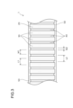
- FIG. 1 is an explanatory diagram illustrating a guidewire 1 according to a first embodiment.
- the guidewire 1 will be described with reference to Figs. 1 to 6.
- the sizes of the components of the guidewire 1 shown in Figs. 1 to 4 are merely examples, and may be expressed on a scale different from the actual size.
- the guidewire 1 is a medical device that is inserted into blood vessels or digestive organs and is used primarily to insert other medical devices, such as catheters, into the body.
- the guidewire 1 has a core shaft 10 (Fig. 2), a first coating 20, a resin coating 50, and a coil 60.
- the resin coating 50 is permeable, so the components inside the resin coating 50 are also shown in Figs. 1 and 3.
- the first coating 20 has a convex portion 30 and a concave portion 40, as described below.
- FIG. 2 is an explanatory diagram illustrating a longitudinal section of the guide wire 1.
- the core shaft 10 is a long member extending along the longitudinal direction of the guide wire 1.
- the outer diameter of the core shaft 10 gradually decreases toward the tip side.
- the core shaft 10 has, in order from the tip side to the rear end side of the core shaft 10, a first straight portion 11, a tapered portion 12, and a second straight portion 13.
- the first straight portion 11 includes the tip portion of the core shaft 10.
- the second straight portion 13 includes the rear end portion of the core shaft 10.
- the outer diameter of the first straight portion 11 is approximately constant in the longitudinal direction of the core shaft 10.
- the outer diameter of the first straight portion 11 is the smallest in the core shaft 10.
- the outer diameter of the second straight portion 13 is approximately constant in the longitudinal direction of the core shaft 10.
- the outer diameter of the second straight portion 13 is the largest in the core shaft 10.
- the tapered portion 12 is provided between the first straight portion 11 and the second straight portion 13.
- the outer diameter of the tapered portion 12 gradually decreases toward the tip.
- the cross sections of the first straight portion 11, the tapered portion 12, and the second straight portion 13 are each circular.
- the material of the core shaft 10 is not particularly limited.
- the material of the core shaft 10 may be stainless steel (SUS302, SUS304, SUS316, etc.), superelastic alloys such as Ni-Ti alloys, piano wire, nickel-chromium alloys, cobalt alloys, platinum, gold, tungsten, etc.
- the first coating 20 is a thin film that covers a part of the tapered portion 12 of the core shaft 10 and the outer periphery of the second straight portion 13. Details of the first coating 20 will be described later.
- the coil 60 is formed by wire 61 wound in a spiral shape around the outer periphery of the core shaft 10 along the longitudinal direction of the core shaft 10.
- the tip of the coil 60 and the tip of the core shaft 10 are joined by a joint 70.
- the rear end of the coil 60 and the tapered section 12 of the core shaft 10 are joined by a joint 71.
- the material of the coil 60 is not particularly limited.
- the material of the coil 60 may be stainless steel (SUS302, SUS304, SUS316, etc.), superelastic alloys such as Ni-Ti alloys, piano wire, nickel-chromium alloys, cobalt alloys, platinum, gold, tungsten, etc.
- the material of the joints (70, 71) is not particularly limited.
- the material of the joints (70, 71) may be, for example, a solder material (aluminum alloy solder, silver solder, gold solder, etc.), a metal solder (Ag-Sn alloy, Au-Sn alloy, etc.), an adhesive (epoxy adhesive, etc.), etc.
- the resin coating 50 is a thin film made of resin.
- the resin coating 50 covers the outer periphery of each of the first coating 20, the coil 60, the joint 70, and the joint 71.
- the resin coating 50 can be formed from a hydrophobic resin material, a hydrophilic resin material, or a mixture of these.
- a hydrophobic resin material for example, silicone resin, polyurethane, polyethylene, polyvinyl chloride, polyester, polypropylene, polyamide, polystyrene, polyolefin elastomer, polyester elastomer, polyamide elastomer, polyurethane elastomer, etc. can be used.
- hydrophilic resin material for example, starch-based materials such as carboxymethyl starch, cellulose-based materials such as carboxymethyl cellulose, polysaccharides such as alginic acid, chitin, chitosan, and hyaluronic acid, natural water-soluble polymeric substances such as gelatin, and synthetic water-soluble polymeric substances such as polyvinyl alcohol, polyethylene oxide, polyethylene glycol, polypropylene glycol, polyvinylpyrrolidone, and water-soluble nylon can be used.
- starch-based materials such as carboxymethyl starch
- cellulose-based materials such as carboxymethyl cellulose
- polysaccharides such as alginic acid, chitin, chitosan, and hyaluronic acid
- natural water-soluble polymeric substances such as gelatin
- synthetic water-soluble polymeric substances such as polyvinyl alcohol, polyethylene oxide, polyethylene glycol, polypropylene glycol, polyvinylpyrrolidone, and water-soluble nylon
- ⁇ Details of the first coating 20> 3 is an explanatory diagram illustrating a part of the appearance of the first coating 20.
- the first coating 20 is a thin film that covers a part of the outer periphery of the core shaft 10 (FIG. 2).
- the first coating 20 is a film-like oxide formed by combining a metal material contained in the core shaft 10 with oxygen. That is, the first coating 20 in this embodiment is an oxide coating formed by oxidizing the surface of the core shaft 10.
- the first coating 20 has a protrusion 30 and a recess 40.
- the convex portion 30 is a part of the first coating 20.
- the convex portion 30 is adjacent to the concave portion 40 when viewed in the radial direction of the core shaft 10.
- the convex portion 30 is located radially outward of the core shaft 10 relative to the concave portion 40.
- the convex portion 30 has a fine uneven shape on its outer surface.
- the surface roughness of the convex portion 30 (hereinafter referred to as "surface roughness S1”) is greater than the surface roughness of the core shaft 10 (hereinafter referred to as "surface roughness S2"). In other words, when the relationship between the surface roughness S1 and the surface roughness S2 is expressed by an inequality sign, S1>S2.
- the surface roughness S1 of the convex portion 30 in this embodiment, expressed by the root mean square height (Sq), is 0.01 ⁇ m to 10 ⁇ m.
- the surface roughness S2 of the core shaft 10 in this embodiment, expressed by the root mean square height (Sq), is 0.001 ⁇ m to 5 ⁇ m.
- the surface roughness S2 of the core shaft 10 refers to the surface roughness of the portion of the core shaft 10 that is not covered by the first coating 20. In this embodiment, it refers to the surface roughness of the first straight portion 11 and the surface roughness of the tip side of the tapered portion 12 that is not covered by the first coating 20.
- the distance between adjacent convex portions 30 in the longitudinal direction of the core shaft 10 is referred to as “distance L1," and the length of the convex portion 30 itself in the longitudinal direction of the core shaft 10 is referred to as “width W1.”
- the distances L1 between adjacent convex portions 30 are substantially the same.
- the widths W1 of the convex portions 30 are substantially the same.
- the recesses 40 are portions of the first coating 20 that are recessed radially inward of the core shaft 10 relative to the protrusions 30.
- the recesses 40 are linear and extend circumferentially of the core shaft 10.
- a plurality of recesses 40 are formed along the longitudinal direction of the core shaft 10.
- the distance between adjacent recesses 40 in the longitudinal direction of the core shaft 10 is referred to as the "distance L2”
- the length of the recess 40 itself in the longitudinal direction of the core shaft 10 is referred to as the "width W2" of the recess 40.
- the distances L2 between adjacent recesses 40 are substantially the same.
- the widths W2 of the recesses 40 in this embodiment are substantially the same.
- FIG. 4 is an explanatory diagram illustrating a portion of the longitudinal section of the core shaft 10.
- the film thickness of the convex portion 30 is called “film thickness T1" and the film thickness of the concave portion 40 is called “film thickness T2".
- the concave portion 40 is recessed radially inward of the core shaft 10, so the film thickness T2 of the concave portion 40 is smaller than the film thickness T1 of the convex portion 30.
- the film thickness T1 of the convex portion 30 in this embodiment is about 0.1 ⁇ m to about 10 ⁇ m.
- the film thickness of a dense film formed on the surface of a specific metal material, generally called a "passive film”, is about several nm.
- the so-called passive film and the first film 20 of this embodiment have different film thicknesses.
- the film thickness of the first film 20 is larger than the film thickness of a general passive film.
- the thickness of the first film 20 is drawn larger than the actual ratio for the purpose of explanation.
- the thickness of the first coating 20 is relatively smaller than the outer diameter of the core shaft 10 (approximately 0.2 mm to approximately 1.0 mm), the effect of the first coating 20 on the outer diameter of the guidewire 1 is small.
- a method for manufacturing the first coating 20 is illustrated. First, a core shaft 10 having a first straight portion 11, a tapered portion 12, and a second straight portion 13 is produced by grinding a metal wire. The core shaft 10 is rotated around the long axis of the core shaft 10, and a laser is irradiated to the outer circumferential surface of the core shaft 10. The first coating 20 is formed on the portion directly irradiated with the laser (hereinafter referred to as the "irradiated portion"). As a result, the heat of the laser is transferred to the periphery of the irradiated portion (hereinafter referred to as the "peripheral portion"). This promotes an oxidation reaction in the peripheral portion, and the first coating 20 is also formed in the peripheral portion.
- the core shaft 10 is locally evaporated by the laser. As a result, the core shaft 10 is recessed radially inward, and a recess 40 is formed. In the peripheral portion, a fine uneven shape is generated as the first coating 20 is formed, and a protrusion 30 is formed.
- the first coating 20 can also be formed by a known chemical surface treatment, such as a passivation treatment in which a coating is formed by immersing the core shaft 10 in a treatment liquid containing an oxidizing agent.
- a passivation treatment in which a coating is formed by immersing the core shaft 10 in a treatment liquid containing an oxidizing agent.
- FIG. 5 and 6 are respectively electron microscope (SEM) photographs of the first coating 20 of the first embodiment.
- FIG. 5 is an SEM photograph of the first coating 20 of the first embodiment observed at 100x magnification.
- FIG. 6 is an SEM photograph of the first coating 20 of the first embodiment observed at 1000x magnification.
- FIG. 5 and FIG. 6 show a part of the first coating 20 formed by laser heating on the outer periphery of the core shaft 10 (FIG. 2) made of a stainless steel alloy. As described above, a plurality of convex portions 30 and a plurality of concave portions 40 are alternately formed along the longitudinal direction of the core shaft 10.
- the fine uneven shape of the convex portions 30 is shown as being closer to black the deeper the concave portions are, and closer to white the higher the convex portions are.
- a part of the concave portions 40 is melted by heat and solidified into a spherical shape.
- the first coating 20 has unevenness at the interface between the recessed portion 40 and the protruding portion 30 when viewed in the radial direction of the core shaft 10. More specifically, referring to FIG. 6, when viewed in the radial direction of the core shaft 10, the boundary between the recessed portion 40 and the protruding portion 30 has a wavy shape. In other words, at the interface between the protruding portion 30 and the recessed portion 40, a portion that protrudes toward the recessed portion 40 and a portion that is recessed toward the opposite side of the recessed portion 40 are repeated in the circumferential direction of the core shaft 10.
- the first coating 20 is formed on a part of the tapered portion 12 of the core shaft 10 and on the outer periphery of the second straight portion 13.
- the formation range of the first coating 20 on the core shaft 10 can be set arbitrarily.
- the first coating 20 may be formed on the outer periphery of the first straight portion 11, and does not have to be formed on the outer periphery of the second straight portion 13.
- the first coating 20 may be formed on the outer periphery of a member other than the core shaft 10, for example, on the outer periphery of the coil 60, joint portion 70, and joint portion 71. In such a case, the adhesion between the member on whose outer periphery the first coating 20 is formed and the resin coating 50 covering those outer peripheries is improved.
- the guidewire 1 of the present embodiment described above includes a core shaft 10, a first coating 20 covering the outer periphery of the core shaft 10, the first coating 20 having a surface roughness greater than that of the core shaft 10, and a resin coating 50 covering the outer periphery of the first coating 20.
- the contact area between the first coating 20 and the resin coating 50 is greater than the contact area between the outer periphery of the core shaft 10 and the resin coating 50 when the resin coating 50 is formed directly on the outer periphery of the core shaft 10 that does not have the first coating 20. This improves the adhesion between the core shaft 10 and the resin coating 50 of the guidewire 1. In other words, the core shaft 10 and the resin coating 50 of the guidewire 1 are more firmly bonded to each other, and peeling of the resin coating 50 from the core shaft 10 can be suppressed.
- the first coating 20 has a recess 40. A portion of the resin coating 50 penetrates into the recess 40, and the first coating 20 and the resin coating 50 locally engage with each other, thereby further improving the adhesion between the core shaft 10 and the resin coating 50.
- the recess 40 is linear and extends along the circumferential direction of the core shaft 10. This allows the engagement portion between the recess 40 and the resin coating 50 to be formed along the circumferential direction of the core shaft 10, further improving the adhesion between the core shaft 10 and the resin coating 50.
- the first coating 20 further includes a protrusion 30 that is adjacent to the recess 40 when viewed in the radial direction of the core shaft 10 and is located radially outward of the recess 40 on the core shaft 10.
- the first coating 20 has irregularities at the interface between the recess 40 and the protrusion 30.
- a portion of the resin coating 50 penetrates into the irregularities at the interface between the recess 40 and the protrusion 30, and the first coating 20 and the resin coating 50 locally engage with each other, thereby further improving the adhesion between the core shaft 10 and the resin coating 50.
- the first coating 20 is an oxide coating formed by oxidizing the surface of the core shaft 10. This makes it relatively easy to form the first coating 20.
- Second Embodiment 7 is an explanatory diagram illustrating a part of the external appearance of the guidewire 1a of the second embodiment.
- the guidewire 1a of the second embodiment and the guidewire 1 of the first embodiment differ from each other in the aspect of the first coating.
- the explanation of the parts common to the guidewire 1 will be omitted.
- the first coating 20a in the second embodiment has a convex portion 30a and a concave portion 40a.
- the concave portion 40a in the second embodiment is linear and extends along the longitudinal direction of the core shaft 10.
- a plurality of concave portions 40a are formed along the circumferential direction of the core shaft 10.
- the distance between adjacent convex portions 30a in the circumferential direction of the core shaft 10 is called the “distance L1a”
- the length of the convex portion 30a itself in the circumferential direction of the core shaft 10 is called the “width W1a.”
- the distances L1a between adjacent convex portions 30a are approximately the same.
- the widths W1a of the convex portions 30a are approximately the same.
- the distance between adjacent recesses 40a in the circumferential direction of the core shaft 10 is referred to as the "distance L2a," and the length of the recess 40a itself in the circumferential direction of the core shaft 10 is referred to as the “width W2a" of the recess 40a.
- the distances L2a between adjacent recesses 40a are approximately the same.
- the widths W2a of the recesses 40a are approximately the same.
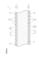
- FIG. 8 is an explanatory diagram illustrating a cross section of the guide wire 1a of the second embodiment.
- multiple recesses 40a are formed at equal intervals from each other in the circumferential direction of the core shaft 10.
- the film thickness of the protrusion 30a is called “film thickness T1a”
- the film thickness of the recess 40a is called “film thickness T2a.” Since the recess 40a is recessed radially inward of the core shaft 10, the film thickness T2a of the recess 40a is smaller than the film thickness T1a of the protrusion 30a.
- the recess 40a is linear and extends along the longitudinal direction of the core shaft 10. This allows the engagement portion between the recess 40a and the resin coating 50 to be formed along the longitudinal direction of the core shaft 10, further improving the adhesion between the core shaft 10 and the resin coating 50.
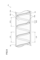
- Third Embodiment 9 is an explanatory diagram illustrating a part of the external appearance of the guidewire 1b of the third embodiment.
- the guidewire 1b of the third embodiment and the guidewire 1 of the first embodiment differ from each other in the aspect of the first coating.
- the description of the parts common to the guidewire 1 will be omitted.
- the first coating 20b in the third embodiment has a convex portion 30b and a concave portion 40b.
- the concave portion 40b in the third embodiment is linear and extends in a spiral shape along the longitudinal direction of the core shaft 10.
- the concave portion 40b is formed continuously from the rear end to the front end of the concave portion 40b.
- the distance between adjacent portions of the protrusion 30b in the longitudinal direction of the core shaft 10 is referred to as “distance L1b,” and the length of the protrusion 30b itself in the longitudinal direction of the core shaft 10 is referred to as “width W1b.”
- the distances L1b between adjacent portions are substantially the same.
- the widths W1b of the protrusions 30b are substantially the same.
- the distance between adjacent portions of the recess 40b in the longitudinal direction of the core shaft 10 is referred to as the "distance L2b," and the length of the recess 40b itself in the longitudinal direction of the core shaft 10 is referred to as the “width W2b" of the recess 40b.
- the distances L2b between adjacent portions are approximately the same.
- the widths W2b of each recess 40b are approximately the same.
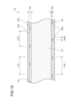
- FIG. 10 is an explanatory diagram illustrating a portion of a longitudinal section of the guidewire 1b of the third embodiment.
- the thickness of the convex portion 30b is called “thickness T1b” and the thickness of the concave portion 40b is called “thickness T2b.” Since the concave portion 40b is recessed radially inward of the core shaft 10, the thickness T2b of the concave portion 40b is smaller than the thickness T1b of the convex portion 30b.
- the recess 40b is linear and extends in a spiral shape along the longitudinal direction of the core shaft 10. This allows the engagement portion between the recess 40b and the resin coating 50 to be formed along the longitudinal direction of the core shaft 10, further improving the adhesion between the core shaft 10 and the resin coating 50.
- Fourth Embodiment 11 is an explanatory diagram illustrating a guidewire 1c of the fourth embodiment.
- the guidewire 1c is different from the guidewire 1 of the first embodiment in that the first coating 20c does not have a recess 40.
- the description of the parts common to the guidewire 1 will be omitted.
- FIG. 12 is an explanatory diagram illustrating a longitudinal section of a guidewire 1c of the fourth embodiment.
- the first coating 20c of the guidewire 1c has a convex portion 30c formed continuously along the longitudinal direction of the core shaft 10.
- the first coating 20c covers a part of the tapered portion 12 of the core shaft 10 and the outer periphery of the second straight portion 13.
- FIG. 13 is an explanatory diagram illustrating a portion of the appearance of the first coating 20.
- FIG. 14 is an explanatory diagram illustrating a portion of a longitudinal cross section of the core shaft 10 of the guidewire 1c of the fourth embodiment.
- the film thickness of the convex portion 30c in this embodiment is referred to as the "film thickness T1c.”
- the film thickness T1c of the convex portion 30c is approximately constant along the longitudinal direction of the core shaft 10.
- FIG. 15 and 16 are respectively electron microscope (SEM) photographs of the first coating 20c of the fourth embodiment.
- FIG. 15 is an SEM photograph of the first coating 20c of the fourth embodiment observed at 100x magnification.
- FIG. 16 is an SEM photograph of the first coating 20c of the fourth embodiment observed at 1000x magnification.
- FIG. 15 and FIG. 16 show a part of the first coating 20c formed by laser heating on the outer periphery of the core shaft 10 (FIG. 2) made of a stainless steel alloy. In the core shaft 10 shown in FIG. 15 and FIG.
- the surface of the core shaft 10 is irradiated with a laser adjusted to an output level that does not significantly evaporate the outer periphery of the core shaft 10, and the outer periphery of the core shaft 10 is heated to form the first coating 20c.
- the fine uneven shape of the convex portion 30c is represented as being closer to black the deeper the concave portion, and closer to white the higher the convex portion.
- the guidewire 1c described above can also improve the adhesion between the core shaft 10 and the resin coating 50.
- Fifth Embodiment 17 is an explanatory diagram illustrating a portion of a longitudinal section of a guidewire 1d of a fifth embodiment.
- the guidewire 1d of the fifth embodiment differs from the guidewire 1 of the first embodiment in that it has a second coating 80, which will be described later.
- the description of the parts common to the guidewire 1 will be omitted.
- the guide wire 1d has a core shaft 10, a first coating 20, a resin coating 50, and a coil 60.
- the guide wire 1d further has a second coating 80.
- the second coating 80 is a thin film that covers the outer circumference of the wire 61. In this embodiment, the second coating 80 covers a part of the wire 61. The tip of the wire 61 is not covered by the second coating 80. The rear end of the wire 61 is not covered by the second coating 80.
- the resin coating 50 covers the outer circumference of the second coating 80.
- the second coating 80 is a film-like oxide formed by the metal material contained in the wire 61 bonding with oxygen. That is, the second coating 80 in this embodiment is an oxide coating formed by oxidation of the surface of the wire 61.
- the surface roughness of the second coating 80 (hereinafter referred to as “surface roughness S3”) is greater than the surface roughness of the wire 61 (hereinafter referred to as “surface roughness S4").
- surface roughness S3 when the relationship between the surface roughness S3 and the surface roughness S4 is expressed by an inequality sign, S3>S4.
- the surface roughness S3 of the second coating 80 in this embodiment expressed by the root mean square height (Sq), is 0.01 ⁇ m to 10 ⁇ m.
- the surface roughness S4 of the wire 61 in this embodiment, expressed by the root mean square height (Sq) is approximately 0.001 ⁇ m to 5 ⁇ m.
- the surface roughness S4 of the wire 61 in this embodiment refers to the surface roughness of the portion of the wire 61 that is not covered by the second coating 80. In this embodiment, it refers to the surface roughness of the portion of the wire 61 that is not covered by the second coating 80 located at the tip and rear ends.
- the guidewire 1d of the present embodiment described above has a core shaft 10, a first coating 20 covering the outer periphery of the core shaft 10, and a resin coating 50 covering the outer periphery of the first coating 20.
- the guidewire 1d further has a coil 60 including a strand 61 wound in a spiral shape around the outer periphery of the core shaft 10, and a second coating 80 covering the outer periphery of the strand 61.
- the resin coating 50 covers the outer periphery of the second coating 80, and the surface roughness of the second coating 80 is greater than the surface roughness of the strand 61.
- the contact area between the second coating 80 and the resin coating 50 is greater than the contact area between the outer periphery of the strand 61 and the resin coating 50 when the resin coating 50 is formed directly on the outer periphery of the strand 61 that does not have the second coating 80. This improves the adhesion between the strand 61 and the resin coating 50 of the guidewire 1d. In other words, the wires 61 and the resin coating 50 of the guidewire 1d are more firmly bonded, and peeling of the resin coating 50 from the wires 61 can be prevented.
- the recess 40 is formed along the circumferential direction of the core shaft 10.
- the recess does not have to be formed around the entire circumferential circumference of the core shaft, but may be formed over half the circumferential length of the core shaft.
- the recess is not limited to being linear, and may be formed in, for example, a dot shape. Even in these cases, the adhesion between the core shaft and the resin coating can be improved.
- the coil 60 of the guidewire (1, 1c, 1d) of the first, fourth, and fifth embodiments covers the outer periphery of the first straight portion 11 and part of the outer periphery of the tapered portion 12.
- the length of the coil can be set arbitrarily, and may be, for example, a length that covers only a part of the tip side of the first straight portion.
- the guidewire does not have to have a coil, and may have a core shaft, an oxide coating that covers the outer periphery of the core shaft, and a resin coating.
- the first coating does not necessarily have to be an oxide coating.
- the second coating does not necessarily have to be an oxide coating.
Landscapes
- Health & Medical Sciences (AREA)
- Life Sciences & Earth Sciences (AREA)
- Biophysics (AREA)
- Pulmonology (AREA)
- Engineering & Computer Science (AREA)
- Anesthesiology (AREA)
- Biomedical Technology (AREA)
- Heart & Thoracic Surgery (AREA)
- Hematology (AREA)
- Animal Behavior & Ethology (AREA)
- General Health & Medical Sciences (AREA)
- Public Health (AREA)
- Veterinary Medicine (AREA)
- Media Introduction/Drainage Providing Device (AREA)
Priority Applications (1)
| Application Number | Priority Date | Filing Date | Title |
|---|---|---|---|
| JP2025505346A JPWO2024185772A1 (https=) | 2023-03-07 | 2024-03-05 |
Applications Claiming Priority (2)
| Application Number | Priority Date | Filing Date | Title |
|---|---|---|---|
| JP2023-035062 | 2023-03-07 | ||
| JP2023035062 | 2023-03-07 |
Publications (1)
| Publication Number | Publication Date |
|---|---|
| WO2024185772A1 true WO2024185772A1 (ja) | 2024-09-12 |
Family
ID=92675218
Family Applications (1)
| Application Number | Title | Priority Date | Filing Date |
|---|---|---|---|
| PCT/JP2024/008289 Ceased WO2024185772A1 (ja) | 2023-03-07 | 2024-03-05 | ガイドワイヤ |
Country Status (2)
| Country | Link |
|---|---|
| JP (1) | JPWO2024185772A1 (https=) |
| WO (1) | WO2024185772A1 (https=) |
Citations (4)
| Publication number | Priority date | Publication date | Assignee | Title |
|---|---|---|---|---|
| US20050096665A1 (en) * | 2003-10-30 | 2005-05-05 | Scimed Life Systems, Inc. | Guidewire having a helically contoured portion |
| JP2011152211A (ja) * | 2010-01-26 | 2011-08-11 | Piolax Medical Device:Kk | ガイドワイヤ |
| JP2013013449A (ja) * | 2011-06-30 | 2013-01-24 | Asahi Intecc Co Ltd | ガイドワイヤ |
| JP2013172926A (ja) * | 2012-02-27 | 2013-09-05 | Japan Lifeline Co Ltd | 医療用ガイドワイヤ |
-
2024
- 2024-03-05 WO PCT/JP2024/008289 patent/WO2024185772A1/ja not_active Ceased
- 2024-03-05 JP JP2025505346A patent/JPWO2024185772A1/ja active Pending
Patent Citations (4)
| Publication number | Priority date | Publication date | Assignee | Title |
|---|---|---|---|---|
| US20050096665A1 (en) * | 2003-10-30 | 2005-05-05 | Scimed Life Systems, Inc. | Guidewire having a helically contoured portion |
| JP2011152211A (ja) * | 2010-01-26 | 2011-08-11 | Piolax Medical Device:Kk | ガイドワイヤ |
| JP2013013449A (ja) * | 2011-06-30 | 2013-01-24 | Asahi Intecc Co Ltd | ガイドワイヤ |
| JP2013172926A (ja) * | 2012-02-27 | 2013-09-05 | Japan Lifeline Co Ltd | 医療用ガイドワイヤ |
Also Published As
| Publication number | Publication date |
|---|---|
| JPWO2024185772A1 (https=) | 2024-09-12 |
Similar Documents
| Publication | Publication Date | Title |
|---|---|---|
| JP4991694B2 (ja) | 親水性を高め治療薬を送達するための新規な外表面積と貯留部を有するワイヤガイド | |
| JP6765415B2 (ja) | ガイドワイヤ | |
| JPH08308933A (ja) | 医療用チューブ | |
| WO2024185772A1 (ja) | ガイドワイヤ | |
| JP2017169751A (ja) | ガイドワイヤ | |
| JP5946186B2 (ja) | コイル体 | |
| JP6046804B2 (ja) | コイル、ガイドワイヤおよびコイルの製造方法 | |
| JP2013192914A (ja) | ガイドワイヤ | |
| CN115003362B (zh) | 导丝 | |
| JP6850368B2 (ja) | カテーテル | |
| JP7746717B2 (ja) | カテーテル、カテーテルの製造方法、及び造影マーカのかしめ方法 | |
| JP7748835B2 (ja) | ガイドワイヤ | |
| JP7474589B2 (ja) | ガイドワイヤ、ガイドワイヤの製造方法 | |
| WO2024116319A1 (ja) | 医療デバイス、医療デバイスの製造方法 | |
| JP7529799B2 (ja) | ガイドワイヤ | |
| JP2014100333A (ja) | カテーテル用チューブの製造方法、カテーテル用チューブの連続体およびカテーテル用チューブ製造用の芯線 | |
| WO2021060249A1 (ja) | ガイドワイヤ | |
| JP2025005471A (ja) | ガイドワイヤ | |
| JP7541948B2 (ja) | ガイドワイヤ | |
| WO2025075126A1 (ja) | 医療デバイス | |
| JP2026055187A (ja) | ガイドワイヤ | |
| KR20230144761A (ko) | 의료용 마이크로 가이드 와이어 | |
| WO2025074816A1 (ja) | ガイドワイヤ | |
| JP2017164039A (ja) | ガイドワイヤ | |
| WO2025239114A1 (ja) | カテーテル |
Legal Events
| Date | Code | Title | Description |
|---|---|---|---|
| 121 | Ep: the epo has been informed by wipo that ep was designated in this application |
Ref document number: 24767139 Country of ref document: EP Kind code of ref document: A1 |
|
| ENP | Entry into the national phase |
Ref document number: 2025505346 Country of ref document: JP Kind code of ref document: A |
|
| WWE | Wipo information: entry into national phase |
Ref document number: 2025505346 Country of ref document: JP |
|
| NENP | Non-entry into the national phase |
Ref country code: DE |
|
| 122 | Ep: pct application non-entry in european phase |
Ref document number: 24767139 Country of ref document: EP Kind code of ref document: A1 |