WO2024185768A1 - 高強度鋼板およびその製造方法 - Google Patents
高強度鋼板およびその製造方法 Download PDFInfo
- Publication number
- WO2024185768A1 WO2024185768A1 PCT/JP2024/008249 JP2024008249W WO2024185768A1 WO 2024185768 A1 WO2024185768 A1 WO 2024185768A1 JP 2024008249 W JP2024008249 W JP 2024008249W WO 2024185768 A1 WO2024185768 A1 WO 2024185768A1
- Authority
- WO
- WIPO (PCT)
- Prior art keywords
- less
- steel sheet
- cold
- heat treatment
- rolled steel
- Prior art date
- Legal status (The legal status is an assumption and is not a legal conclusion. Google has not performed a legal analysis and makes no representation as to the accuracy of the status listed.)
- Ceased
Links
Images



Classifications
-
- C—CHEMISTRY; METALLURGY
- C23—COATING METALLIC MATERIAL; COATING MATERIAL WITH METALLIC MATERIAL; CHEMICAL SURFACE TREATMENT; DIFFUSION TREATMENT OF METALLIC MATERIAL; COATING BY VACUUM EVAPORATION, BY SPUTTERING, BY ION IMPLANTATION OR BY CHEMICAL VAPOUR DEPOSITION, IN GENERAL; INHIBITING CORROSION OF METALLIC MATERIAL OR INCRUSTATION IN GENERAL
- C23G—CLEANING OR DE-GREASING OF METALLIC MATERIAL BY CHEMICAL METHODS OTHER THAN ELECTROLYSIS
- C23G1/00—Cleaning or pickling metallic material with solutions or molten salts
- C23G1/02—Cleaning or pickling metallic material with solutions or molten salts with acid solutions
- C23G1/08—Iron or steel
-
- C—CHEMISTRY; METALLURGY
- C21—METALLURGY OF IRON
- C21D—MODIFYING THE PHYSICAL STRUCTURE OF FERROUS METALS; GENERAL DEVICES FOR HEAT TREATMENT OF FERROUS OR NON-FERROUS METALS OR ALLOYS; MAKING METAL MALLEABLE, e.g. BY DECARBURISATION OR TEMPERING
- C21D1/00—General methods or devices for heat treatment, e.g. annealing, hardening, quenching or tempering
- C21D1/18—Hardening; Quenching with or without subsequent tempering
- C21D1/25—Hardening, combined with annealing between 300 degrees Celsius and 600 degrees Celsius, i.e. heat refining ("Vergüten")
-
- C—CHEMISTRY; METALLURGY
- C21—METALLURGY OF IRON
- C21D—MODIFYING THE PHYSICAL STRUCTURE OF FERROUS METALS; GENERAL DEVICES FOR HEAT TREATMENT OF FERROUS OR NON-FERROUS METALS OR ALLOYS; MAKING METAL MALLEABLE, e.g. BY DECARBURISATION OR TEMPERING
- C21D6/00—Heat treatment of ferrous alloys
- C21D6/005—Heat treatment of ferrous alloys containing Mn
-
- C—CHEMISTRY; METALLURGY
- C21—METALLURGY OF IRON
- C21D—MODIFYING THE PHYSICAL STRUCTURE OF FERROUS METALS; GENERAL DEVICES FOR HEAT TREATMENT OF FERROUS OR NON-FERROUS METALS OR ALLOYS; MAKING METAL MALLEABLE, e.g. BY DECARBURISATION OR TEMPERING
- C21D8/00—Modifying the physical properties of ferrous metals or ferrous alloys by deformation combined with, or followed by, heat treatment
- C21D8/02—Modifying the physical properties of ferrous metals or ferrous alloys by deformation combined with, or followed by, heat treatment during manufacturing of plates or strips
-
- C—CHEMISTRY; METALLURGY
- C21—METALLURGY OF IRON
- C21D—MODIFYING THE PHYSICAL STRUCTURE OF FERROUS METALS; GENERAL DEVICES FOR HEAT TREATMENT OF FERROUS OR NON-FERROUS METALS OR ALLOYS; MAKING METAL MALLEABLE, e.g. BY DECARBURISATION OR TEMPERING
- C21D8/00—Modifying the physical properties of ferrous metals or ferrous alloys by deformation combined with, or followed by, heat treatment
- C21D8/02—Modifying the physical properties of ferrous metals or ferrous alloys by deformation combined with, or followed by, heat treatment during manufacturing of plates or strips
- C21D8/0221—Modifying the physical properties of ferrous metals or ferrous alloys by deformation combined with, or followed by, heat treatment during manufacturing of plates or strips characterised by the working steps
- C21D8/0226—Hot rolling
-
- C—CHEMISTRY; METALLURGY
- C21—METALLURGY OF IRON
- C21D—MODIFYING THE PHYSICAL STRUCTURE OF FERROUS METALS; GENERAL DEVICES FOR HEAT TREATMENT OF FERROUS OR NON-FERROUS METALS OR ALLOYS; MAKING METAL MALLEABLE, e.g. BY DECARBURISATION OR TEMPERING
- C21D8/00—Modifying the physical properties of ferrous metals or ferrous alloys by deformation combined with, or followed by, heat treatment
- C21D8/02—Modifying the physical properties of ferrous metals or ferrous alloys by deformation combined with, or followed by, heat treatment during manufacturing of plates or strips
- C21D8/0221—Modifying the physical properties of ferrous metals or ferrous alloys by deformation combined with, or followed by, heat treatment during manufacturing of plates or strips characterised by the working steps
- C21D8/0236—Cold rolling
-
- C—CHEMISTRY; METALLURGY
- C21—METALLURGY OF IRON
- C21D—MODIFYING THE PHYSICAL STRUCTURE OF FERROUS METALS; GENERAL DEVICES FOR HEAT TREATMENT OF FERROUS OR NON-FERROUS METALS OR ALLOYS; MAKING METAL MALLEABLE, e.g. BY DECARBURISATION OR TEMPERING
- C21D8/00—Modifying the physical properties of ferrous metals or ferrous alloys by deformation combined with, or followed by, heat treatment
- C21D8/02—Modifying the physical properties of ferrous metals or ferrous alloys by deformation combined with, or followed by, heat treatment during manufacturing of plates or strips
- C21D8/0247—Modifying the physical properties of ferrous metals or ferrous alloys by deformation combined with, or followed by, heat treatment during manufacturing of plates or strips characterised by the heat treatment
- C21D8/0263—Modifying the physical properties of ferrous metals or ferrous alloys by deformation combined with, or followed by, heat treatment during manufacturing of plates or strips characterised by the heat treatment following hot rolling
-
- C—CHEMISTRY; METALLURGY
- C21—METALLURGY OF IRON
- C21D—MODIFYING THE PHYSICAL STRUCTURE OF FERROUS METALS; GENERAL DEVICES FOR HEAT TREATMENT OF FERROUS OR NON-FERROUS METALS OR ALLOYS; MAKING METAL MALLEABLE, e.g. BY DECARBURISATION OR TEMPERING
- C21D8/00—Modifying the physical properties of ferrous metals or ferrous alloys by deformation combined with, or followed by, heat treatment
- C21D8/02—Modifying the physical properties of ferrous metals or ferrous alloys by deformation combined with, or followed by, heat treatment during manufacturing of plates or strips
- C21D8/0247—Modifying the physical properties of ferrous metals or ferrous alloys by deformation combined with, or followed by, heat treatment during manufacturing of plates or strips characterised by the heat treatment
- C21D8/0273—Final recrystallisation annealing
-
- C—CHEMISTRY; METALLURGY
- C21—METALLURGY OF IRON
- C21D—MODIFYING THE PHYSICAL STRUCTURE OF FERROUS METALS; GENERAL DEVICES FOR HEAT TREATMENT OF FERROUS OR NON-FERROUS METALS OR ALLOYS; MAKING METAL MALLEABLE, e.g. BY DECARBURISATION OR TEMPERING
- C21D9/00—Heat treatment, e.g. annealing, hardening, quenching or tempering, adapted for particular articles; Furnaces therefor
- C21D9/46—Heat treatment, e.g. annealing, hardening, quenching or tempering, adapted for particular articles; Furnaces therefor for sheet metals
-
- C—CHEMISTRY; METALLURGY
- C22—METALLURGY; FERROUS OR NON-FERROUS ALLOYS; TREATMENT OF ALLOYS OR NON-FERROUS METALS
- C22C—ALLOYS
- C22C38/00—Ferrous alloys, e.g. steel alloys
- C22C38/002—Ferrous alloys, e.g. steel alloys containing In, Mg, or other elements not provided for in one single group C22C38/001 - C22C38/60
-
- C—CHEMISTRY; METALLURGY
- C22—METALLURGY; FERROUS OR NON-FERROUS ALLOYS; TREATMENT OF ALLOYS OR NON-FERROUS METALS
- C22C—ALLOYS
- C22C38/00—Ferrous alloys, e.g. steel alloys
- C22C38/005—Ferrous alloys, e.g. steel alloys containing rare earths, i.e. Sc, Y, Lanthanides
-
- C—CHEMISTRY; METALLURGY
- C22—METALLURGY; FERROUS OR NON-FERROUS ALLOYS; TREATMENT OF ALLOYS OR NON-FERROUS METALS
- C22C—ALLOYS
- C22C38/00—Ferrous alloys, e.g. steel alloys
- C22C38/02—Ferrous alloys, e.g. steel alloys containing silicon
-
- C—CHEMISTRY; METALLURGY
- C22—METALLURGY; FERROUS OR NON-FERROUS ALLOYS; TREATMENT OF ALLOYS OR NON-FERROUS METALS
- C22C—ALLOYS
- C22C38/00—Ferrous alloys, e.g. steel alloys
- C22C38/04—Ferrous alloys, e.g. steel alloys containing manganese
-
- C—CHEMISTRY; METALLURGY
- C22—METALLURGY; FERROUS OR NON-FERROUS ALLOYS; TREATMENT OF ALLOYS OR NON-FERROUS METALS
- C22C—ALLOYS
- C22C38/00—Ferrous alloys, e.g. steel alloys
- C22C38/06—Ferrous alloys, e.g. steel alloys containing aluminium
-
- C—CHEMISTRY; METALLURGY
- C22—METALLURGY; FERROUS OR NON-FERROUS ALLOYS; TREATMENT OF ALLOYS OR NON-FERROUS METALS
- C22C—ALLOYS
- C22C38/00—Ferrous alloys, e.g. steel alloys
- C22C38/10—Ferrous alloys, e.g. steel alloys containing cobalt
-
- C—CHEMISTRY; METALLURGY
- C22—METALLURGY; FERROUS OR NON-FERROUS ALLOYS; TREATMENT OF ALLOYS OR NON-FERROUS METALS
- C22C—ALLOYS
- C22C38/00—Ferrous alloys, e.g. steel alloys
- C22C38/12—Ferrous alloys, e.g. steel alloys containing tungsten, tantalum, molybdenum, vanadium, or niobium
-
- C—CHEMISTRY; METALLURGY
- C22—METALLURGY; FERROUS OR NON-FERROUS ALLOYS; TREATMENT OF ALLOYS OR NON-FERROUS METALS
- C22C—ALLOYS
- C22C38/00—Ferrous alloys, e.g. steel alloys
- C22C38/14—Ferrous alloys, e.g. steel alloys containing titanium or zirconium
-
- C—CHEMISTRY; METALLURGY
- C22—METALLURGY; FERROUS OR NON-FERROUS ALLOYS; TREATMENT OF ALLOYS OR NON-FERROUS METALS
- C22C—ALLOYS
- C22C38/00—Ferrous alloys, e.g. steel alloys
- C22C38/16—Ferrous alloys, e.g. steel alloys containing copper
-
- C—CHEMISTRY; METALLURGY
- C22—METALLURGY; FERROUS OR NON-FERROUS ALLOYS; TREATMENT OF ALLOYS OR NON-FERROUS METALS
- C22C—ALLOYS
- C22C38/00—Ferrous alloys, e.g. steel alloys
- C22C38/18—Ferrous alloys, e.g. steel alloys containing chromium
- C22C38/26—Ferrous alloys, e.g. steel alloys containing chromium with niobium or tantalum
-
- C—CHEMISTRY; METALLURGY
- C22—METALLURGY; FERROUS OR NON-FERROUS ALLOYS; TREATMENT OF ALLOYS OR NON-FERROUS METALS
- C22C—ALLOYS
- C22C38/00—Ferrous alloys, e.g. steel alloys
- C22C38/18—Ferrous alloys, e.g. steel alloys containing chromium
- C22C38/38—Ferrous alloys, e.g. steel alloys containing chromium with more than 1.5% by weight of manganese
-
- C—CHEMISTRY; METALLURGY
- C23—COATING METALLIC MATERIAL; COATING MATERIAL WITH METALLIC MATERIAL; CHEMICAL SURFACE TREATMENT; DIFFUSION TREATMENT OF METALLIC MATERIAL; COATING BY VACUUM EVAPORATION, BY SPUTTERING, BY ION IMPLANTATION OR BY CHEMICAL VAPOUR DEPOSITION, IN GENERAL; INHIBITING CORROSION OF METALLIC MATERIAL OR INCRUSTATION IN GENERAL
- C23C—COATING METALLIC MATERIAL; COATING MATERIAL WITH METALLIC MATERIAL; SURFACE TREATMENT OF METALLIC MATERIAL BY DIFFUSION INTO THE SURFACE, BY CHEMICAL CONVERSION OR SUBSTITUTION; COATING BY VACUUM EVAPORATION, BY SPUTTERING, BY ION IMPLANTATION OR BY CHEMICAL VAPOUR DEPOSITION, IN GENERAL
- C23C2/00—Hot-dipping or immersion processes for applying the coating material in the molten state without affecting the shape; Apparatus therefor
- C23C2/02—Pretreatment of the material to be coated, e.g. for coating on selected surface areas
-
- C—CHEMISTRY; METALLURGY
- C23—COATING METALLIC MATERIAL; COATING MATERIAL WITH METALLIC MATERIAL; CHEMICAL SURFACE TREATMENT; DIFFUSION TREATMENT OF METALLIC MATERIAL; COATING BY VACUUM EVAPORATION, BY SPUTTERING, BY ION IMPLANTATION OR BY CHEMICAL VAPOUR DEPOSITION, IN GENERAL; INHIBITING CORROSION OF METALLIC MATERIAL OR INCRUSTATION IN GENERAL
- C23C—COATING METALLIC MATERIAL; COATING MATERIAL WITH METALLIC MATERIAL; SURFACE TREATMENT OF METALLIC MATERIAL BY DIFFUSION INTO THE SURFACE, BY CHEMICAL CONVERSION OR SUBSTITUTION; COATING BY VACUUM EVAPORATION, BY SPUTTERING, BY ION IMPLANTATION OR BY CHEMICAL VAPOUR DEPOSITION, IN GENERAL
- C23C2/00—Hot-dipping or immersion processes for applying the coating material in the molten state without affecting the shape; Apparatus therefor
- C23C2/02—Pretreatment of the material to be coated, e.g. for coating on selected surface areas
- C23C2/022—Pretreatment of the material to be coated, e.g. for coating on selected surface areas by heating
- C23C2/0224—Two or more thermal pretreatments
-
- C—CHEMISTRY; METALLURGY
- C23—COATING METALLIC MATERIAL; COATING MATERIAL WITH METALLIC MATERIAL; CHEMICAL SURFACE TREATMENT; DIFFUSION TREATMENT OF METALLIC MATERIAL; COATING BY VACUUM EVAPORATION, BY SPUTTERING, BY ION IMPLANTATION OR BY CHEMICAL VAPOUR DEPOSITION, IN GENERAL; INHIBITING CORROSION OF METALLIC MATERIAL OR INCRUSTATION IN GENERAL
- C23C—COATING METALLIC MATERIAL; COATING MATERIAL WITH METALLIC MATERIAL; SURFACE TREATMENT OF METALLIC MATERIAL BY DIFFUSION INTO THE SURFACE, BY CHEMICAL CONVERSION OR SUBSTITUTION; COATING BY VACUUM EVAPORATION, BY SPUTTERING, BY ION IMPLANTATION OR BY CHEMICAL VAPOUR DEPOSITION, IN GENERAL
- C23C2/00—Hot-dipping or immersion processes for applying the coating material in the molten state without affecting the shape; Apparatus therefor
- C23C2/04—Hot-dipping or immersion processes for applying the coating material in the molten state without affecting the shape; Apparatus therefor characterised by the coating material
- C23C2/06—Zinc or cadmium or alloys based thereon
-
- C—CHEMISTRY; METALLURGY
- C23—COATING METALLIC MATERIAL; COATING MATERIAL WITH METALLIC MATERIAL; CHEMICAL SURFACE TREATMENT; DIFFUSION TREATMENT OF METALLIC MATERIAL; COATING BY VACUUM EVAPORATION, BY SPUTTERING, BY ION IMPLANTATION OR BY CHEMICAL VAPOUR DEPOSITION, IN GENERAL; INHIBITING CORROSION OF METALLIC MATERIAL OR INCRUSTATION IN GENERAL
- C23C—COATING METALLIC MATERIAL; COATING MATERIAL WITH METALLIC MATERIAL; SURFACE TREATMENT OF METALLIC MATERIAL BY DIFFUSION INTO THE SURFACE, BY CHEMICAL CONVERSION OR SUBSTITUTION; COATING BY VACUUM EVAPORATION, BY SPUTTERING, BY ION IMPLANTATION OR BY CHEMICAL VAPOUR DEPOSITION, IN GENERAL
- C23C2/00—Hot-dipping or immersion processes for applying the coating material in the molten state without affecting the shape; Apparatus therefor
- C23C2/26—After-treatment
- C23C2/28—Thermal after-treatment, e.g. treatment in oil bath
-
- C—CHEMISTRY; METALLURGY
- C23—COATING METALLIC MATERIAL; COATING MATERIAL WITH METALLIC MATERIAL; CHEMICAL SURFACE TREATMENT; DIFFUSION TREATMENT OF METALLIC MATERIAL; COATING BY VACUUM EVAPORATION, BY SPUTTERING, BY ION IMPLANTATION OR BY CHEMICAL VAPOUR DEPOSITION, IN GENERAL; INHIBITING CORROSION OF METALLIC MATERIAL OR INCRUSTATION IN GENERAL
- C23C—COATING METALLIC MATERIAL; COATING MATERIAL WITH METALLIC MATERIAL; SURFACE TREATMENT OF METALLIC MATERIAL BY DIFFUSION INTO THE SURFACE, BY CHEMICAL CONVERSION OR SUBSTITUTION; COATING BY VACUUM EVAPORATION, BY SPUTTERING, BY ION IMPLANTATION OR BY CHEMICAL VAPOUR DEPOSITION, IN GENERAL
- C23C2/00—Hot-dipping or immersion processes for applying the coating material in the molten state without affecting the shape; Apparatus therefor
- C23C2/26—After-treatment
- C23C2/28—Thermal after-treatment, e.g. treatment in oil bath
- C23C2/29—Cooling or quenching
-
- C—CHEMISTRY; METALLURGY
- C23—COATING METALLIC MATERIAL; COATING MATERIAL WITH METALLIC MATERIAL; CHEMICAL SURFACE TREATMENT; DIFFUSION TREATMENT OF METALLIC MATERIAL; COATING BY VACUUM EVAPORATION, BY SPUTTERING, BY ION IMPLANTATION OR BY CHEMICAL VAPOUR DEPOSITION, IN GENERAL; INHIBITING CORROSION OF METALLIC MATERIAL OR INCRUSTATION IN GENERAL
- C23C—COATING METALLIC MATERIAL; COATING MATERIAL WITH METALLIC MATERIAL; SURFACE TREATMENT OF METALLIC MATERIAL BY DIFFUSION INTO THE SURFACE, BY CHEMICAL CONVERSION OR SUBSTITUTION; COATING BY VACUUM EVAPORATION, BY SPUTTERING, BY ION IMPLANTATION OR BY CHEMICAL VAPOUR DEPOSITION, IN GENERAL
- C23C2/00—Hot-dipping or immersion processes for applying the coating material in the molten state without affecting the shape; Apparatus therefor
- C23C2/34—Hot-dipping or immersion processes for applying the coating material in the molten state without affecting the shape; Apparatus therefor characterised by the shape of the material to be treated
- C23C2/36—Elongated material
- C23C2/40—Plates; Strips
-
- C—CHEMISTRY; METALLURGY
- C25—ELECTROLYTIC OR ELECTROPHORETIC PROCESSES; APPARATUS THEREFOR
- C25D—PROCESSES FOR THE ELECTROLYTIC OR ELECTROPHORETIC PRODUCTION OF COATINGS; ELECTROFORMING; APPARATUS THEREFOR
- C25D3/00—Electroplating: Baths therefor
- C25D3/02—Electroplating: Baths therefor from solutions
- C25D3/22—Electroplating: Baths therefor from solutions of zinc
-
- C—CHEMISTRY; METALLURGY
- C21—METALLURGY OF IRON
- C21D—MODIFYING THE PHYSICAL STRUCTURE OF FERROUS METALS; GENERAL DEVICES FOR HEAT TREATMENT OF FERROUS OR NON-FERROUS METALS OR ALLOYS; MAKING METAL MALLEABLE, e.g. BY DECARBURISATION OR TEMPERING
- C21D2211/00—Microstructure comprising significant phases
- C21D2211/001—Austenite
-
- C—CHEMISTRY; METALLURGY
- C21—METALLURGY OF IRON
- C21D—MODIFYING THE PHYSICAL STRUCTURE OF FERROUS METALS; GENERAL DEVICES FOR HEAT TREATMENT OF FERROUS OR NON-FERROUS METALS OR ALLOYS; MAKING METAL MALLEABLE, e.g. BY DECARBURISATION OR TEMPERING
- C21D2211/00—Microstructure comprising significant phases
- C21D2211/002—Bainite
-
- C—CHEMISTRY; METALLURGY
- C21—METALLURGY OF IRON
- C21D—MODIFYING THE PHYSICAL STRUCTURE OF FERROUS METALS; GENERAL DEVICES FOR HEAT TREATMENT OF FERROUS OR NON-FERROUS METALS OR ALLOYS; MAKING METAL MALLEABLE, e.g. BY DECARBURISATION OR TEMPERING
- C21D2211/00—Microstructure comprising significant phases
- C21D2211/005—Ferrite
-
- C—CHEMISTRY; METALLURGY
- C21—METALLURGY OF IRON
- C21D—MODIFYING THE PHYSICAL STRUCTURE OF FERROUS METALS; GENERAL DEVICES FOR HEAT TREATMENT OF FERROUS OR NON-FERROUS METALS OR ALLOYS; MAKING METAL MALLEABLE, e.g. BY DECARBURISATION OR TEMPERING
- C21D2211/00—Microstructure comprising significant phases
- C21D2211/008—Martensite
Definitions
- the present invention relates to high-strength steel plates and manufacturing methods thereof.
- automotive frame parts have many end faces that are formed by shearing, and it is required that these sheared end faces do not develop cracks due to bending (bending).
- the shape of the sheared edge depends on the shear clearance, and the occurrence of cracks at the sheared edge also depends on the shear clearance. For this reason, high-strength steel sheets used in automobiles are required to have a wide optimum clearance range for bending of the sheared end faces.
- the present invention aims to provide a high-strength steel plate having a tensile strength (TS) of 980 MPa or more, excellent ductility and resistance to delayed fracture, and a wide optimum clearance range for bending of the shear end face, as well as a manufacturing method thereof.
- TS tensile strength
- a high-strength steel plate comprising: a steel plate having a component composition containing, by mass%, C: 0.030% or more and 0.500% or less, Si: 0.50% or more and 2.50% or less, Mn: 1.50% or more and 5.00% or less, P: 0.100% or less, S: 0.0200% or less, Al: 1.000% or less, N: 0.0100% or less, O: 0.0100% or less, and Nb: 0.005% or more and 0.100% or less, with the balance being Fe and unavoidable impurities; and a microstructure having an amount of martensite of 60% or more, an amount of retained austenite of 3% or more and 20% or less, and a total amount of ferrite and bainitic ferrite of more than 10%, wherein the non-stability index k of retained austenite is less than 5.9, and the non-stability index d of retained austenite at an
- a method for producing a high-strength steel sheet comprising: a heat treatment B in which the cold-rolled steel sheet is held at a temperature T2 of 5 seconds to 1000 seconds from the cooling stop temperature Ta to a temperature T2 of 150° C. to 400° C. after the heat treatment B; and a heat treatment C in which the cold-rolled steel sheet is cooled without being held at the temperature T3, and an average cooling rate v4 from 150° C. to 50° C. is 1.0° C./h to 50.0° C./h in the heat treatment C; and after the heat treatment A and before the heat treatment C, the cold-rolled steel sheet is processed to impart an equivalent plastic strain of 0.10% to 5.00% to the cold-rolled steel sheet.
- the Ms point is expressed in °C and is calculated by the following formula (a).
- Ms 519-474 ⁇ [%C]-30.4 ⁇ [%Mn]-12.1 ⁇ [%Cr]-7.5 ⁇ [%Mo]-17.7 ⁇ [%Ni]...(a)
- [% M] is the content of element M in the above composition, and is 0 when element M is not contained.
- the present invention provides a high-strength steel plate with a tensile strength (TS) of 980 MPa or more, excellent ductility and resistance to delayed fracture, and a wide optimum clearance range for bending the shear end surface.
- TS tensile strength
- FIG. 2 is a schematic diagram showing a test piece used in a tensile test.
- 1 is a graph showing a schematic diagram of the relationship between the tensile stress and the tensile strain applied to a test piece during a tensile test.
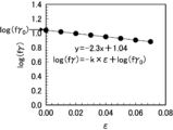
- 1 is an example of a graph showing the relationship between tensile strain ⁇ and the amount of retained austenite.
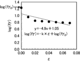
- 1 is another example of a graph showing the relationship between tensile strain ⁇ and the amount of retained austenite.
- 13 is yet another example of a graph showing the relationship between tensile strain ⁇ and the amount of retained austenite.
- the high-strength steel plate of this embodiment includes a steel plate, and may further include a plating layer on the surface of this steel plate, as described below.
- the steel plate of the present high strength steel plate has a component composition and a microstructure (steel structure) described below, and satisfies the instability index k and the instability index d described below.
- High strength means a tensile strength (TS) of 980 MPa or greater.
- This high-strength steel plate has a tensile strength (TS) of 980 MPa or more, excellent ductility and resistance to delayed fracture, and a wide optimum clearance range for bending of the shear end face.
- TS tensile strength
- the optimum clearance range for bending of the sheared end surface will also be simply referred to as the "optimum clearance range.”
- the present inventors have conducted extensive research and have found the following. (1) By making the amount of martensite 60% or more, a TS of 980 MPa or more can be realized. (2) By making the total amount of ferrite and bainitic ferrite more than 10% and making the amount of retained austenite 3% or more, excellent ductility can be realized. (3) By making the instability index d of the retained austenite at the initial stage of working less than 5.8 and making the amount of retained austenite 20% or less, excellent delayed fracture resistance can be realized. (4) By setting the instability index k of the retained austenite to less than 5.9 and the instability index d of the retained austenite at the initial stage of processing to less than 5.8, a wide optimum clearance range can be realized.
- this high-strength steel plate By applying this high-strength steel plate to, for example, the structural components of an automobile, it is possible to improve fuel efficiency by reducing the weight of the vehicle body. Therefore, the industrial value of this steel plate is extremely high.
- the thickness of the steel plate is not particularly limited and is, for example, 0.5 mm or more and 3.0 mm or less.
- composition The chemical composition of the steel plate of the present high strength steel plate (hereinafter also referred to as “the present chemical composition”) will be described. Unless otherwise specified, "%" in the component composition means “% by mass”.
- C (C: 0.030% or more and 0.500% or less) C is one of the important basic components of steel, and is an element that affects the amount of martensite and the total amount of ferrite and bainitic ferrite. If the C content is too low, the amount of martensite decreases, making it difficult to achieve a TS of 980 MPa or more. Therefore, the C content is 0.030% or more, and preferably 0.050% or more. , 0.100% or more is more preferable. On the other hand, if the C content is too high, the martensite becomes embrittled and the delayed fracture resistance property is deteriorated. Therefore, the C content is 0.500% or less, preferably 0.400% or less, and more preferably 0.350% or less. % or less is more preferable.
- Si 0.50% or more and 2.50% or less
- Si is one of the important basic components of steel, and is an element that affects TS and the amount of retained austenite. If the Si content is too low, the strength of martensite decreases, making it difficult to achieve a TS of 980 MPa or more. Therefore, the Si content is set to 0.50% or more, and 0.55% or more. is preferable, and 0.60% or more is more preferable. On the other hand, if the Si content is too high, the amount of retained austenite increases excessively, and the delayed fracture resistance property decreases. Therefore, the Si content is 2.50% or less, and preferably 2.00% or less. It is more preferable that the content is 1.80% or less.
- Mn is one of the important basic components of steel, and is an element that affects the amount of martensite and the total amount of ferrite and bainitic ferrite. If the Mn content is too low, the amount of martensite decreases, making it difficult to achieve a TS of 980 MPa or more. Therefore, the Mn content is 1.50% or more, and preferably 2.00% or more. , 2.20% or more is more preferable. On the other hand, if the Mn content is too high, the martensite becomes embrittled and the delayed fracture resistance property is deteriorated. Therefore, the Mn content is 5.00% or less, preferably 4.50% or less, and more preferably 4.00% or less. % or less is more preferable.
- the P content is set to 0.100% or less.
- the content is preferably 0.070% or less, and more preferably 0.030% or less.
- the lower limit is not particularly limited.
- P is a solid solution strengthening element and can increase the strength of the steel sheet. Therefore, the P content is preferably 0.001% or more, and more preferably 0.003% or more. More preferably, the content is 0.005% or more, and even more preferably 0.005% or more.
- the S content is 0.0200% or less, and preferably 0.0050% or less. It is more preferable that the content is 0.0025% or less. Although there is no particular lower limit, due to constraints on production technology, the S content is preferably 0.0001% or more, more preferably 0.0003% or more, and even more preferably 0.0005% or more.
- Al (Al: 1.000% or less) Al exists as an oxide and embrittles the steel sheet, which reduces the delayed fracture resistance. Therefore, the Al content is 1.000% or less, and preferably 0.500% or less. The content is more preferably 0.150% or less, and further preferably 0.070% or less. The lower limit is not particularly limited. However, Al can suppress the formation of carbides during the heat treatment described below and promote the formation of retained austenite. For this reason, the Al content is preferably 0.001% or more. , 0.005% or more is more preferable, and 0.010% or more is even more preferable.
- N (N: 0.0100% or less) N exists as a nitride and embrittles the steel sheet, thereby reducing the delayed fracture resistance. Therefore, the N content is 0.0100% or less, and preferably 0.0080% or less. It is more preferable that the content is 0.0050% or less. Although there is no particular lower limit, due to constraints on production technology, the N content is preferably 0.0001% or more, more preferably 0.0005% or more, and even more preferably 0.0010% or more.
- the O content is 0.0100% or less, and preferably 0.0080% or less. It is more preferable that the content is 0.0050% or less. Although there is no particular lower limit, due to constraints on production technology, the O content is preferably 0.0001% or more, more preferably 0.0007% or more, and even more preferably 0.0015% or more.
- Nb 0.005% or more and 0.100% or less
- the present inventors have found that Nb affects the instability index k of retained austenite. If the Nb content is too low, the structure after the heat treatment described below becomes coarse, and the instability index k of the retained austenite increases. This narrows the optimum clearance range. For this reason, the Nb content is set to 0.005%. The content is preferably 0.008% or more, and more preferably 0.010% or more. On the other hand, if the Nb content is too high, the martensite becomes embrittled and the delayed fracture resistance property is deteriorated. Therefore, the Nb content is 0.100% or less, preferably 0.080% or less, and more preferably 0.050% or less. % or less is more preferable.
- composition may further contain, by mass %, at least one element (other element) selected from the group consisting of the elements described below.
- the Ti and V contents are each 0.200% or less, preferably 0.150% or less, and more preferably 0.100% or less.
- the lower limit is not particularly limited.
- Ti and V form fine carbides, nitrides, or carbonitrides during hot rolling or heat treatment described later, thereby increasing the strength of the steel sheet. Therefore, the contents of Ti and V are preferably 0.001% or more, more preferably 0.005% or more, and further preferably 0.015% or more, respectively.
- the Ta and W contents are each 0.10% or less, preferably 0.09% or less, and more preferably 0.08% or less.
- the lower limit is not particularly limited.
- Ta and W increase the strength of the steel sheet by forming fine carbides, nitrides, or carbonitrides during hot rolling or heat treatment described later. Therefore, the contents of Ta and W are preferably 0.01% or more, more preferably 0.03% or more, and further preferably 0.05% or more, respectively.
- the content of B is 0.0100% or less, preferably 0.0080% or less, and more preferably 0.0060% or less.
- the lower limit is not particularly limited.
- B segregates at the austenite grain boundaries during the heat treatment described below to improve hardenability. Therefore, the B content is preferably 0.0003% or more, more preferably 0.0005% or more, and even more preferably 0.0010% or more.
- the Cr, Mo and Ni contents are each 1.00% or less, preferably 0.80% or less, and more preferably 0.50% or less.
- the contents of Cr, Mo and Ni are each preferably 0.01% or more, more preferably 0.04% or more, and further preferably 0.08% or more.
- the Co content is 0.010% or less, preferably 0.008% or less, and more preferably 0.006% or less.
- the lower limit is not particularly limited. However, since Co is an element that improves hardenability, the Co content is preferably 0.001% or more, more preferably 0.003% or more, and further preferably 0.005% or more.
- the Cu content is 1.00% or less, preferably 0.80% or less, and more preferably 0.60% or less.
- the lower limit is not particularly limited. However, since Cu is an element that improves hardenability, the Cu content is preferably 0.01% or more, more preferably 0.03% or more, and further preferably 0.05% or more.
- the Sn content is 0.200% or less, preferably 0.150% or less, and more preferably 0.100% or less.
- the lower limit is not particularly limited.
- the Sn content is preferably 0.001% or more, more preferably 0.010% or more, and further preferably 0.020% or more.
- the Sb content is 0.200% or less, preferably 0.150% or less, and more preferably 0.100% or less.
- the lower limit is not particularly limited.
- the Sb content is preferably 0.001% or more, more preferably 0.003% or more, and even more preferably 0.005% or more.
- the contents of Ca, Mg and REM are each 0.0100% or less, preferably 0.0080% or less, and more preferably 0.0050% or less.
- the lower limit is not particularly limited.
- Ca, Mg and REM are elements that spheroidize the shape of nitrides and sulfides and improve the ultimate deformability of the steel sheet. Therefore, the contents of Ca, Mg and REM are each preferably 0.0005% or more, more preferably 0.0010% or more, and even more preferably 0.0015% or more.
- the Zr and Te contents are each 0.100% or less, preferably 0.080% or less, and more preferably 0.060% or less.
- the lower limit is not particularly limited.
- Zr and Te are elements that make the shape of nitrides and sulfides spheroidal and improve the ultimate deformability of the steel sheet. Therefore, the contents of Zr and Te are preferably 0.001% or more, more preferably 0.008% or more, and further preferably 0.015% or more, respectively.
- the Hf content is 0.10% or less, preferably 0.09% or less, and more preferably 0.08% or less.
- the lower limit is not particularly limited.
- Hf is an element that spheroidizes the shape of nitrides and sulfides and improves the ultimate deformability of the steel sheet. Therefore, the Hf content is preferably 0.01% or more, more preferably 0.02% or more, and even more preferably 0.03% or more.
- the Bi content is 0.200% or less, preferably 0.150% or less, and more preferably 0.100% or less.
- the lower limit is not particularly limited.
- the Bi content is preferably 0.001% or more, more preferably 0.020% or more, further preferably 0.050% or more, and particularly preferably 0.090% or more.
- the balance in this composition is Fe and unavoidable impurities.
- the microstructure of the present high strength steel plate (hereinafter also referred to as “the present microstructure”) will be described.
- Total amount of ferrite and bainitic ferrite is more than 10%
- the lower limit is not particularly limited, but is preferably 45% or less, more preferably 40% or less, and even more preferably 35% or less.
- the amount of ferrite and the amount of bainitic ferrite are determined as follows.
- the steel plate is polished to expose the L-section at 1/4 of the plate thickness (a position corresponding to 1/4 of the plate thickness in the depth direction from the surface of the steel plate) as an observation surface.
- the observation surface is corroded with 3% by volume of nital, and then observed in 10 fields of view at a magnification of 2000 times using a scanning electron microscope (SEM) to obtain SEM images of each field of view.
- SEM scanning electron microscope
- ferrite and bainitic ferrite are confirmed as structures with flat concave structures inside.
- the area ratios (unit: %) of ferrite and bainitic ferrite in each SEM image are obtained, and the average value of the area ratios obtained for the 10 fields of view is taken as the total amount of ferrite and bainitic ferrite.
- the amount of retained austenite is 3% or more, preferably 5% or more, more preferably 7% or more, and even more preferably 8% or more.
- the amount of retained austenite is 20% or less, preferably 15% or less, and more preferably 13% or less.
- the amount of retained austenite is determined as follows.
- the steel sheet is polished to expose an L-section at a position 0.1 mm deeper than the 1/4 position of the sheet thickness. This L-section is further polished by chemical polishing to a depth of 0.1 mm to obtain an observation surface.
- an integrated intensity ratio of the diffraction peak is obtained using CoK ⁇ radiation in an X-ray diffraction (XRD) device. More specifically, the integrated intensity ratio of the diffraction peak of each of the ⁇ 200 ⁇ , ⁇ 220 ⁇ , and ⁇ 311 ⁇ planes of fcc iron and each of the ⁇ 200 ⁇ , ⁇ 211 ⁇ , and ⁇ 220 ⁇ planes of bcc iron is obtained.
- the average value of the nine integrated intensity ratios is taken as the volume fraction (unit: %) of the amount of retained austenite, and this is taken as the amount of retained austenite.
- the amount of martensite is 60% or more, preferably 65% or more, and more preferably 70% or more, because a TS of 980 MPa or more can be realized.
- the contribution of tempered martensite is important in achieving a high TS, and the amount of tempered martensite is preferably 65% or more.
- the amount of martensite is determined as follows. First, the amount of retained austenite, and the total amount of ferrite and bainitic ferrite are calculated by the above-mentioned method, and then the total is subtracted from 100% to obtain the amount of martensite (unit: %). Therefore, the amount of martensite referred to here includes both quenched martensite and tempered martensite. As described above, the amount of retained austenite is a volume fraction, which is approximately equal to the area fraction, so the amount of retained austenite is subtracted from 100% together with the total amount of ferrite and bainitic ferrite, which is an area fraction.
- the instability index k of retained austenite affects the optimum clearance range. If the non-stability index k is too high, the stability of the retained austenite is low and the retained austenite is excessively transformed into hard martensite during shearing, which reduces the ultimate deformability of the steel plate and narrows the optimum clearance range. For this reason, the instability index k is less than 5.9, preferably 5.0 or less, more preferably 4.0 or less, and even more preferably 3.5 or less. Although there is no particular lower limit, the instability index k is, for example, 1.0 or more, preferably 1.5 or more, and more preferably 2.0 or more.
- non-stability index d of retained austenite at the initial stage of working (also simply referred to as "non-stability index d”) affects delayed fracture resistance and the optimum clearance range. If the non-stability index d is too high, the stability of the retained austenite at the initial stage of processing is low, and the retained austenite is excessively transformed into hard martensite at the initial stage of processing, which becomes the starting point of delayed fracture in a hydrogen penetration environment, thereby deteriorating the delayed fracture resistance.
- the instability index d is less than 5.8, preferably 5.0 or less, more preferably 4.0 or less, and even more preferably 3.5 or less.
- the instability index d is, for example, ⁇ 15.0 or more, preferably ⁇ 10.0 or more, and more preferably ⁇ 5.0 or more.
- Fig. 1 is a schematic diagram showing a test piece used in a tensile test.
- Fig. 2 is a graph showing a relationship between a tensile stress and a tensile strain applied to the test piece 1 during the tensile test. As shown in Fig. 2, a tensile stress is applied to the test piece to impart a tensile strain (tensile plastic strain).
- the obtained approximation is applied to the following formula (1), and the slope a of the approximation is determined as the instability index k of retained austenite.
- log(f ⁇ ) -k ⁇ +log(f ⁇ 0 )...(1)
- f ⁇ represents the amount of retained austenite when a tensile strain ⁇ is applied
- f ⁇ 0 represents the amount of retained austenite before working.
- Fig. 3 is an example of a graph showing the relationship between tensile strain ⁇ and the amount of retained austenite
- Fig. 4 is another example of the same graph
- Fig. 5 is yet another example of the same graph. Comparing FIG. 3 with FIG. 4, the slope a (instability index k) of the approximation equation in FIG. 3 is 2.3, which is smaller than the slope a (instability index k) of the approximation equation in FIG. 4, which is 6.0.
- a small slope a (non-stability index k) of the approximation equation indicates that the change in the amount of retained austenite during processing is small and the stability of the retained austenite is good.
- the slope a of the approximation equation (instability index k) is small at 4.9.
- the slope of the approximation equation is large in the initial stage of processing (the initial stage of the tensile test). In other words, in this case, the stability of the retained austenite in the initial stage of processing is insufficient.
- the retained austenite has excellent stability both during processing and at the initial stage of processing.
- the high-strength steel sheet may further have a plating layer on the surface of the steel sheet.
- the plated layer include a hot-dip galvanized layer, a galvannealed hot-dip galvanized layer, and an electrolytic galvanized layer.
- the plated layer is formed by a plating process described later.
- the coating weight of the plating layer is not particularly limited, but is preferably 20 to 80 g/ m2 per side.
- the present production method is also a method for producing the present high-strength steel plate described above.
- the temperatures at which steel slabs, steel plates, etc. are heated or cooled below refer to the surface temperatures of the steel slabs, steel plates, etc., unless otherwise specified.
- the method for producing molten steel to become a steel slab is not particularly limited, and may be a known method using a converter, an electric furnace, etc. From the viewpoint of preventing macrosegregation, it is preferable to obtain a steel slab from molten steel by a continuous casting method.
- ⁇ Hot rolling> In the present manufacturing method, first, a steel slab having the present chemical composition described above is held at a slab heating temperature explained below, and then hot-rolled to obtain a hot-rolled steel sheet.
- the slab heating temperature is preferably 1220°C or higher, more preferably 1230°C or higher, and even more preferably higher than 1230°C. Although there is no particular upper limit, the slab heating temperature is preferably 1300° C. or less, more preferably 1290° C. or less, and further preferably 1280° C. or less.
- the average cooling rate v 1 from 800° C. to 600° C. (also simply referred to as the “average cooling rate v 1 ”) affects the instability index k of retained austenite. found. If the average cooling rate v1 is too small, coarse Nb-based carbides are excessively precipitated during cooling, and the effect of Nb in reducing the instability index k of the retained austenite is reduced. As a result, the instability index k increases. This narrows the optimum clearance range. Therefore, the average cooling rate v1 is 30° C./s or more, preferably 35° C./s or more, and more preferably 40° C./s or more.
- the cooled hot-rolled steel sheet is subjected to pickling and cold rolling to obtain a cold-rolled sheet.
- Pickling is important for ensuring good chemical conversion treatability and plating quality in the final product, a high-strength steel sheet, because it can remove oxides from the surface of the hot-rolled steel sheet.
- Pickling may be performed once or multiple times.
- the hot-rolled steel sheet is pickled to obtain a pickled sheet, which is then dried as appropriate.
- the cold rolling may be performed on the pickled sheet before drying, or may be performed after drying.
- the reduction ratio in cold rolling and the thickness after rolling are not particularly limited.
- the number of rolling passes and the reduction ratio of each pass are also not particularly limited.
- the cold-rolled steel sheet obtained by cold rolling is subjected to heat treatment A, heat treatment B, and heat treatment C, which will be described later, in this order.
- heat treatment C processing, which will be described later, is carried out. This will be explained in more detail below.
- a heat treatment A is applied to a cold-rolled steel sheet obtained by cold rolling.
- the cold-rolled steel sheet is held (heated) at a temperature T1 described later, and then cooled to a cooling stop temperature Ta described later.
- the conditions of the heat treatment A are explained below.
- ⁇ Temperature T1 750°C or more and 900°C or less ⁇
- the cold-rolled steel sheet is held (heated) at a temperature T1. If the temperature T1 is too low, the amount of martensite decreases, making it difficult to achieve a TS of 980 MPa or more. For this reason, the temperature T1 is set to: The temperature is 750° C. or higher, preferably 780° C. or higher, and more preferably 800° C. or higher. On the other hand, if the temperature T1 is too high, the total amount of ferrite and bainitic ferrite is reduced, making it difficult to achieve excellent ductility. For this reason, the temperature T1 is set to 900° C. or less and 880° C. or less. Preferably, the temperature is 850° C. or lower, and more preferably, 850° C. or lower.
- ⁇ Holding time t1 10 seconds or more and 1000 seconds or less ⁇ If the time (holding time t 1 ) for holding (heating) the cold-rolled steel sheet at temperature T1 is too short, the amount of martensite decreases, making it difficult to achieve a TS of 980 MPa or more. 1 is 10 seconds or more, preferably 30 seconds or more, and more preferably 50 seconds or more. On the other hand, if the holding time t1 is too long, the total amount of ferrite and bainitic ferrite decreases, making it difficult to achieve excellent ductility. For this reason, the holding time t1 is set to 1000 seconds or less. The time is preferably 500 seconds or less, and more preferably 300 seconds or less.
- ⁇ Cooling stop temperature Ta 100°C or higher (Ms point -80°C) or lower ⁇
- the cold-rolled steel sheet held at temperature T1 is cooled to a cooling stop temperature Ta. If the cooling stop temperature Ta is too low, the amount of retained austenite decreases and the ductility decreases, so the cooling stop temperature Ta is 100° C. or higher, preferably 120° C. or higher, and more preferably 140° C. or higher. On the other hand, if the cooling stop temperature Ta is too high, the amount of retained austenite increases excessively, and the delayed fracture resistance property decreases.
- the cooling stop temperature Ta is set to (Ms point - 80°C) or lower, and (Ms The melting point is preferably (Ms point -90°C) or less, and more preferably (Ms point -100°C) or less.
- the average cooling rate in the temperature range described below is controlled to the range described below.
- Average cooling rate v2 less than 20°C/s If the average cooling rate v2 from 750°C to 600°C (also simply referred to as "average cooling rate v2 ”) is too large, the total amount of ferrite and bainitic ferrite decreases, making it difficult to achieve excellent ductility. For this reason, the average cooling rate v2 is less than 20°C/s, preferably 19°C/s or less, and more preferably 17°C/s or less. Although there is no particular lower limit, the average cooling rate v2 is, for example, 3° C./s or more, preferably 5° C./s or more, and more preferably 8° C./s or more.
- ⁇ Average cooling rate v3 150°C/s or less ⁇
- the average cooling rate v 3 from the Ms point to the cooling stop temperature Ta (also simply referred to as the “average cooling rate v 3 ”) is an instability index of the retained austenite in the initial stage of processing. It was found that the effect of the .DELTA..times ... If the average cooling rate v3 is too large, the martensite transformation rate is fast, which causes the retained austenite to coarsen, and the instability index d of the retained austenite at the initial stage of processing to increase. This results in poor delayed fracture resistance.
- the average cooling rate v3 is 150° C./s or less, preferably 120° C./s or less, and more preferably 90° C./s or less. Although there is no particular lower limit, the average cooling rate v3 is, for example, 5° C./s or more, preferably 8° C./s or more, and more preferably 10° C./s or more.
- ⁇ Tension F 5MPa or more and 100MPa or less ⁇
- tension F also simply referred to as “tension F”
- the tension F is 5 MPa or more, preferably 6 MPa or more, and more preferably 8 MPa or more.
- the tension F should be set to 100 MPa or less.
- the pressure is preferably 50 MPa or less, and more preferably 25 MPa or less.
- the cold-rolled steel sheet cooled to the cooling stop temperature Ta is subjected to a heat treatment B.
- the cold-rolled steel sheet is held (heated) at a temperature T2 described later, and then cooled to a temperature lower than the temperature T2 (for example, room temperature).
- the room temperature is, for example, 25°C.
- the conditions of the heat treatment B are described below.
- ⁇ Temperature T2 Cooling stop temperature Ta or more and 450°C or less ⁇
- the cold-rolled steel sheet is held (heated) at a temperature T2. This stabilizes the retained austenite. If the temperature T2 is too low, the desired amount of retained austenite cannot be obtained, and the ductility decreases. Therefore, the temperature T2 is equal to or higher than the cooling stop temperature Ta, preferably equal to or higher than (Ta+10° C.), and more preferably equal to or higher than (Ta+20° C.). On the other hand, if the temperature T2 is too high, the tempering of martensite proceeds excessively, making it difficult to achieve a TS of 980 MPa or more. For this reason, the temperature T2 is 450° C. or less, and preferably 420° C. or less. , 400° C. or less is more preferable.
- ⁇ Holding time t2 5 seconds or more and 1000 seconds or less ⁇ If the time for which the cold-rolled steel sheet is held at the temperature T2 (holding time t2 ) is too short, the stabilization of austenite becomes insufficient, the instability index k of the retained austenite increases, and the optimum clearance range becomes narrow.
- the retention time t2 is 5 seconds or more, preferably 50 seconds or more, and more preferably 80 seconds or more.
- the holding time t2 is set to 1000 seconds or less and 800 sec or less is preferable, and 400 seconds or less is more preferable.
- the cold-rolled steel sheet is processed to impart an equivalent plastic strain to the cold-rolled steel sheet.
- the temperature during processing is not particularly limited. For example, processing may be performed while the cold-rolled steel sheet is held at temperature T2, or may be performed after the cold-rolled steel sheet is cooled to room temperature after being held at temperature T2.
- Equivalent plastic strain 0.10% to 5.00%
- the equivalent plastic strain also simply referred to as "equivalent plastic strain”
- the equivalent plastic strain is 0.10% or more, preferably 0.15% or more, and more preferably 0.30% or more.
- the equivalent plastic strain is 5.00% or less, preferably 4.00% or less, and more preferably 3.00% or less.
- the number of times the cold-rolled steel sheet is processed is not particularly limited. That is, the processing may be carried out in a plurality of steps, provided that the total equivalent plastic strain imparted to the cold-rolled steel sheet by each processing step falls within the above range. For example, even if the equivalent plastic strain imparted to the cold-rolled steel sheet by the first processing is less than the above-mentioned lower limit value, the total equivalent plastic strain by the second or subsequent processing may be greater than or equal to the above-mentioned lower limit value (or less than or equal to the above-mentioned lower limit value).
- Examples of the method for processing the cold-rolled steel sheet include a method for performing temper rolling on the cold-rolled steel sheet, a method for processing the cold-rolled steel sheet using a tension leveller, etc.
- Examples of the leveller include a tension leveller, a continuous stretcher leveller, a roller leveller, etc., and a tension leveller is preferred.
- the equivalent plastic strain is the elongation rate of the steel sheet (cold-rolled steel sheet) and is determined from the change in length of the steel sheet before and after processing.
- the equivalent plastic strain is calculated according to the method described in Reference 1 below.
- the cold-rolled steel sheet that has been cooled to room temperature is subjected to a heat treatment C.
- the cold-rolled steel sheet is heated to a temperature T3 described below, and then cooled to a temperature lower than the temperature T3 (for example, room temperature) without being held at the temperature T3.
- ⁇ Temperature T3 150°C or more and 400°C or less ⁇ If the temperature T3 is too low, the stabilization of austenite becomes insufficient, and the instability index k of the retained austenite increases, narrowing the optimum clearance range. For this reason, the temperature T3 is set to 150° C. or higher, and 160° C. or lower. The temperature is preferably 170° C. or higher, and more preferably 170° C. or higher. On the other hand, if the temperature T3 is too high, the tempering of martensite proceeds excessively, making it difficult to achieve a TS of 980 MPa or more. For this reason, the temperature T3 is 400° C. or less, and preferably 350° C. or less. , 300° C. or less is more preferable.
- the average cooling rate in the temperature range described below is controlled to the range described below.
- ⁇ Average cooling rate v 4 1.0°C/h or more and 50.0°C/h or less ⁇ If the average cooling rate v 4 from 150° C. to 50° C. (also simply referred to as “average cooling rate v 4 ”) is too large, the concentration of carbon in the austenite during cooling becomes insufficient. Stabilization becomes insufficient, and the instability index k of the retained austenite increases, narrowing the optimum clearance range. For this reason, the average cooling rate v4 is 50.0°C/h or less, and 48.0°C/h or less. /h or less, and more preferably 45.0° C./h or less. On the other hand, due to restrictions on production technology, the average cooling rate v4 is 1.0° C./h or more, preferably 1.2° C./h or more, and more preferably 1.4° C./h or more.
- the cold-rolled steel sheet after the heat treatment C is applied corresponds to the steel sheet of the present high-strength steel sheet described above.
- the cold-rolled steel sheet may be processed to impart an equivalent plastic strain of 0.10% or more and 5.00% or less again.
- the cold-rolled steel sheet may be heated at a temperature of 100°C or more and 400°C or less.
- the cold-rolled steel sheet may be subjected to a plating treatment, whereby a plating layer is formed.
- the plating treatment is carried out, for example, during or after the heat treatment A described above.
- a hot-dip galvanizing treatment or an alloying hot-dip galvanizing treatment (a treatment for alloying after the hot-dip galvanizing treatment) is carried out while the cold-rolled steel sheet is cooled from 750° C. to 600° C. at an average cooling rate v2 (or after this cooling).
- the electrogalvanizing treatment is carried out after the heat treatment B.
- Examples of the electrogalvanizing treatment include a Zn-Ni electric alloy plating treatment and a pure Zn electric plating treatment.
- the plating process is not limited to the above-mentioned hot-dip galvanizing process, galvannealed hot-dip plating process, and electrolytic galvanizing process.
- the metal type used in the plating process is not limited to Zn, and may be other metals (e.g., Al).
- the adhesion weight of the plating layer to be formed can be adjusted.
- Other conditions for the plating treatment are not particularly limited, and the plating treatment may be carried out according to a conventional method. From the viewpoint of productivity, a series of treatments including the above-mentioned heat treatments A to C and the plating treatment is preferably carried out in a continuous hot-dip galvanizing line (CGL).
- CGL continuous hot-dip galvanizing line
- the obtained cold-rolled steel sheet was subjected to heat treatments A to C under the conditions shown in Table 2 below.
- Prior to heat treatment C the cold-rolled steel sheet was processed under the conditions shown in Table 2 below. In this manner, cold-rolled steel sheets having the final thicknesses shown in Table 2 below were obtained.
- a cold-rolled steel sheet was subjected to a plating process (hot-dip galvanizing process, galvannealed hot-dip galvanizing process, or electrogalvanizing process) to obtain a hot-dip galvanized steel sheet (GI), a galvannealed hot-dip galvanized steel sheet (GA), or an electrogalvanized steel sheet (EG).
- the hot-dip galvanizing treatment and the galvannealed hot-dip galvanizing treatment were carried out during the cooling of heat treatment A.
- the electrolytic galvanizing treatment was carried out after heat treatment B (before heat treatment C).
- a zinc bath containing 0.20 mass% Al with the balance being Zn and unavoidable impurities was used when producing GI
- a zinc bath containing 0.14 mass% Al with the balance being Zn and unavoidable impurities was used when producing GA.
- the bath temperature was 470° C. for both GI and GA production.
- the coating weight of the plating layer was 45 to 72 g/ m2 per side when producing GI, and 45 g/ m2 per side when producing GA.
- the alloying temperature was 500°C.
- the composition of the plating layer of GI was Fe: 0.1-1.0 mass%, Al: 0.2-1.0 mass%, with the balance being Zn and unavoidable impurities
- the composition of the plating layer of GA was Fe: 7-15 mass%, Al: 0.1-1.0 mass%, with the balance being Zn and unavoidable impurities.
- cold-rolled steel sheet CR
- hot-dip galvanized steel sheet GI
- alloyed hot-dip galvanized steel sheet G
- electrolytic galvanized steel sheet EG
- Tensile strength and elongation From the obtained steel plate, a JIS No. 5 test piece (gauge length: 50 mm, parallel part width: 25 mm) with the longitudinal direction (tensile direction) perpendicular to the rolling direction was taken. Using the taken test piece, a tensile test was carried out in accordance with JIS Z 2241 at a crosshead speed of 1.67 ⁇ 10 ⁇ 1 mm/sec to determine the tensile strength (TS) and elongation (El). When TS was 980 MPa or more, it was determined that the strength was high. When El was 8% or more, it was determined that the ductility was excellent.
- a test piece (parallel part width: 6 mm, parallel part length: 15 mm) was taken from the obtained steel sheet, with the width direction being parallel to the rolling direction.
- the test piece was ground on all sides to a sheet thickness of 1.0 mm, and then the test was carried out.
- the test piece was immersed in an aqueous solution containing 3 mass% NaCl and 3 g/L NH 4 SCN, and held for 24 hours with an applied current density of 0 or 0.05 mA/cm 2. Thereafter, a tensile test (SSRT test) was carried out at a tensile speed of 5 ⁇ m/min to break the test piece, and the tensile strength (TS) was obtained.
- SSRT test tensile test
- the ratio of TS when the applied current density was 0.05 mA/cm 2 to TS when the applied current density was 0 mA/cm 2 was determined as the stress ratio.
- the stress ratio was rated as "C” when it was less than 0.70, "B” when it was 0.70 or more and less than 0.80, and "A” when it was 0.80 or more. In the case of "B” or "A”, it was determined that the delayed fracture resistance was excellent.
- ⁇ Bending test> A test piece (width: 30 mm, length: 100 mm) with a longitudinal direction perpendicular to the rolling direction was taken from the obtained steel sheet. A bending test was carried out using the taken test piece according to the V-block method described in JIS Z 2248, and the minimum bending radius R at which no cracks were generated at the bending ridge was measured. The occurrence of cracks was confirmed by observing the bent ridgeline at a magnification of 40 times using a digital microscope (RH-2000, manufactured by Hirox Corporation).
- the optimum clearance range for bending the shear end surface was determined as follows. First, the obtained steel plate was sheared to obtain a test piece (width: 30 mm, length: 100 mm) with the longitudinal direction perpendicular to the rolling direction. The rake angle during shearing was standardized to 0°, and the shear clearance was changed to 5%, 10%, 15%, 20%, 25%, 30%, and 35%. The test pieces obtained by shearing were subjected to bending tests using a punch with a minimum bending radius R divided by the plate thickness t (R/t) of 6.0 according to the above-mentioned method, and the sheared end faces of the test pieces were bent (bending process).
- the sheared end faces of the test pieces were checked for the presence or absence of cracks (fissures).
- the occurrence of cracks was confirmed by observing the sheared end surface of the test piece at a magnification of 40 times using a digital microscope (RH-2000, manufactured by Hirox Corporation).
- RH-2000 digital microscope
- the shear clearance range where no cracks occurred on the sheared end face of the test piece was less than 10%, it was marked as "C”, in the case where it was 10% or more but less than 15%, it was marked as "B”, and in the case where it was 15% or more, it was marked as "A” in the following Table 3.
- B or "A it was determined that the optimum clearance range for bending forming of the sheared end face was wide.
- the steel plates Nos. 1 to 8, 10 to 12, 14, 16, 18, 20, 22, 24, 26, 28 to 32, 34 to 36, 38, 40, 42, 44, 46 to 58, 60, 62, 64, 66, 68, 70, 72, 74, 76, 78, 80, 82, 84 to 85, 87 to 88, 90 to 91 and 93 to 113 had a TS of 980 MPa or more, were excellent in ductility and delayed fracture resistance, and had a wide optimum clearance range.
Landscapes
- Chemical & Material Sciences (AREA)
- Engineering & Computer Science (AREA)
- Materials Engineering (AREA)
- Metallurgy (AREA)
- Organic Chemistry (AREA)
- Mechanical Engineering (AREA)
- Thermal Sciences (AREA)
- Physics & Mathematics (AREA)
- Crystallography & Structural Chemistry (AREA)
- Chemical Kinetics & Catalysis (AREA)
- Electrochemistry (AREA)
- General Chemical & Material Sciences (AREA)
- Oil, Petroleum & Natural Gas (AREA)
- Heat Treatment Of Sheet Steel (AREA)
- Heat Treatment Of Steel (AREA)
Priority Applications (5)
| Application Number | Priority Date | Filing Date | Title |
|---|---|---|---|
| KR1020257027206A KR20250137155A (ko) | 2023-03-06 | 2024-03-05 | 고강도 강판 및 그 제조 방법 |
| JP2024538731A JP7666748B2 (ja) | 2023-03-06 | 2024-03-05 | 高強度鋼板およびその製造方法 |
| CN202480012816.8A CN120693419A (zh) | 2023-03-06 | 2024-03-05 | 高强度钢板及其制造方法 |
| EP24767135.7A EP4660345A1 (en) | 2023-03-06 | 2024-03-05 | High-strength steel sheet and manufacturing method therefor |
| MX2025010477A MX2025010477A (es) | 2023-03-06 | 2025-09-04 | Chapa de acero de alta resistencia y metodo de fabricacion de la misma |
Applications Claiming Priority (2)
| Application Number | Priority Date | Filing Date | Title |
|---|---|---|---|
| JP2023033481 | 2023-03-06 | ||
| JP2023-033481 | 2023-03-06 |
Publications (1)
| Publication Number | Publication Date |
|---|---|
| WO2024185768A1 true WO2024185768A1 (ja) | 2024-09-12 |
Family
ID=92675157
Family Applications (1)
| Application Number | Title | Priority Date | Filing Date |
|---|---|---|---|
| PCT/JP2024/008249 Ceased WO2024185768A1 (ja) | 2023-03-06 | 2024-03-05 | 高強度鋼板およびその製造方法 |
Country Status (6)
| Country | Link |
|---|---|
| EP (1) | EP4660345A1 (https=) |
| JP (1) | JP7666748B2 (https=) |
| KR (1) | KR20250137155A (https=) |
| CN (1) | CN120693419A (https=) |
| MX (1) | MX2025010477A (https=) |
| WO (1) | WO2024185768A1 (https=) |
Citations (2)
| Publication number | Priority date | Publication date | Assignee | Title |
|---|---|---|---|---|
| WO2019208556A1 (ja) * | 2018-04-23 | 2019-10-31 | 日本製鉄株式会社 | 鋼部材およびその製造方法 |
| WO2022259838A1 (ja) * | 2021-06-11 | 2022-12-15 | Jfeスチール株式会社 | 高強度鋼板およびその製造方法 |
Family Cites Families (3)
| Publication number | Priority date | Publication date | Assignee | Title |
|---|---|---|---|---|
| JP6306481B2 (ja) | 2014-03-17 | 2018-04-04 | 株式会社神戸製鋼所 | 延性及び曲げ性に優れた高強度冷延鋼板および高強度溶融亜鉛めっき鋼板、並びにそれらの製造方法 |
| KR102460214B1 (ko) | 2018-03-30 | 2022-11-01 | 닛폰세이테츠 가부시키가이샤 | 강판 및 그 제조 방법 |
| JP6809647B1 (ja) | 2019-02-25 | 2021-01-06 | Jfeスチール株式会社 | 高強度鋼板およびその製造方法 |
-
2024
- 2024-03-05 JP JP2024538731A patent/JP7666748B2/ja active Active
- 2024-03-05 EP EP24767135.7A patent/EP4660345A1/en active Pending
- 2024-03-05 WO PCT/JP2024/008249 patent/WO2024185768A1/ja not_active Ceased
- 2024-03-05 KR KR1020257027206A patent/KR20250137155A/ko active Pending
- 2024-03-05 CN CN202480012816.8A patent/CN120693419A/zh active Pending
-
2025
- 2025-09-04 MX MX2025010477A patent/MX2025010477A/es unknown
Patent Citations (2)
| Publication number | Priority date | Publication date | Assignee | Title |
|---|---|---|---|---|
| WO2019208556A1 (ja) * | 2018-04-23 | 2019-10-31 | 日本製鉄株式会社 | 鋼部材およびその製造方法 |
| WO2022259838A1 (ja) * | 2021-06-11 | 2022-12-15 | Jfeスチール株式会社 | 高強度鋼板およびその製造方法 |
Non-Patent Citations (1)
| Title |
|---|
| See also references of EP4660345A1 * |
Also Published As
| Publication number | Publication date |
|---|---|
| EP4660345A1 (en) | 2025-12-10 |
| MX2025010477A (es) | 2025-10-01 |
| KR20250137155A (ko) | 2025-09-17 |
| JP7666748B2 (ja) | 2025-04-22 |
| JPWO2024185768A1 (https=) | 2024-09-12 |
| CN120693419A (zh) | 2025-09-23 |
Similar Documents
| Publication | Publication Date | Title |
|---|---|---|
| JP4725415B2 (ja) | 熱間プレス用鋼板および熱間プレス鋼板部材ならびにそれらの製造方法 | |
| US9109275B2 (en) | High-strength galvanized steel sheet and method of manufacturing the same | |
| JP7215646B1 (ja) | 高強度鋼板およびその製造方法 | |
| CN102803543B (zh) | 高强度热镀锌钢板及其制造方法 | |
| JP7111252B2 (ja) | 被覆鋼部材、被覆鋼板およびそれらの製造方法 | |
| JP2017048412A (ja) | 溶融亜鉛めっき鋼板、合金化溶融亜鉛めっき鋼板、およびそれらの製造方法 | |
| JP2005528519A5 (https=) | ||
| CN104105807A (zh) | 高强度冷轧钢板及其制造方法 | |
| WO2021100842A1 (ja) | 被覆鋼部材、被覆鋼板およびそれらの製造方法 | |
| CN114945690B (zh) | 钢板及其制造方法 | |
| CN115151672A (zh) | 钢板、构件和它们的制造方法 | |
| JP7215647B1 (ja) | 高強度鋼板およびその製造方法 | |
| CN115151673A (zh) | 钢板、构件和它们的制造方法 | |
| CN115210398A (zh) | 钢板、构件和它们的制造方法 | |
| WO2020170530A1 (ja) | 熱間プレス部材およびその製造方法、ならびに熱間プレス部材用鋼板の製造方法 | |
| CN118829738A (zh) | 钢板和构件以及它们的制造方法 | |
| JP2013216936A (ja) | 合金化溶融亜鉛めっき熱延鋼板およびその製造方法 | |
| JP7666748B2 (ja) | 高強度鋼板およびその製造方法 | |
| JP7666749B2 (ja) | 高強度鋼板およびその製造方法 | |
| JPH06145893A (ja) | 延性と耐遅れ破壊特性に優れた高強度溶融亜鉛めっき鋼板およびその製造方法 | |
| CN118215753A (zh) | 钢板和部件以及它们的制造方法 | |
| WO2023047991A1 (ja) | 熱間プレス用鋼板、その製造方法、熱間プレス部材およびその製造方法 | |
| JP7708344B1 (ja) | 亜鉛めっき鋼板および部材、ならびに、それらの製造方法 | |
| JP7323094B1 (ja) | 高強度鋼板およびその製造方法 | |
| CN113544301B (zh) | 钢板 |
Legal Events
| Date | Code | Title | Description |
|---|---|---|---|
| WWE | Wipo information: entry into national phase |
Ref document number: 2024538731 Country of ref document: JP |
|
| 121 | Ep: the epo has been informed by wipo that ep was designated in this application |
Ref document number: 24767135 Country of ref document: EP Kind code of ref document: A1 |
|
| ENP | Entry into the national phase |
Ref document number: 1020257027206 Country of ref document: KR Free format text: ST27 STATUS EVENT CODE: A-0-1-A10-A15-NAP-PA0105 (AS PROVIDED BY THE NATIONAL OFFICE) |
|
| WWE | Wipo information: entry into national phase |
Ref document number: 1020257027206 Country of ref document: KR Ref document number: 202480012816.8 Country of ref document: CN |
|
| WWE | Wipo information: entry into national phase |
Ref document number: 2501005568 Country of ref document: TH |
|
| WWE | Wipo information: entry into national phase |
Ref document number: 202517081147 Country of ref document: IN |
|
| WWP | Wipo information: published in national office |
Ref document number: 202480012816.8 Country of ref document: CN |
|
| WWP | Wipo information: published in national office |
Ref document number: 202517081147 Country of ref document: IN |
|
| NENP | Non-entry into the national phase |
Ref country code: DE |
|
| WWP | Wipo information: published in national office |
Ref document number: 2024767135 Country of ref document: EP |