WO2024185648A1 - 発汗量計測装置及び発汗量計測システム - Google Patents
発汗量計測装置及び発汗量計測システム Download PDFInfo
- Publication number
- WO2024185648A1 WO2024185648A1 PCT/JP2024/007563 JP2024007563W WO2024185648A1 WO 2024185648 A1 WO2024185648 A1 WO 2024185648A1 JP 2024007563 W JP2024007563 W JP 2024007563W WO 2024185648 A1 WO2024185648 A1 WO 2024185648A1
- Authority
- WO
- WIPO (PCT)
- Prior art keywords
- measuring device
- air
- rate measuring
- sweat rate
- sweat
- Prior art date
- Legal status (The legal status is an assumption and is not a legal conclusion. Google has not performed a legal analysis and makes no representation as to the accuracy of the status listed.)
- Ceased
Links
Images


Classifications
-
- A—HUMAN NECESSITIES
- A42—HEADWEAR
- A42B—HATS; HEAD COVERINGS
- A42B3/00—Helmets; Helmet covers ; Other protective head coverings
- A42B3/04—Parts, details or accessories of helmets
- A42B3/28—Ventilating arrangements
-
- A—HUMAN NECESSITIES
- A42—HEADWEAR
- A42B—HATS; HEAD COVERINGS
- A42B3/00—Helmets; Helmet covers ; Other protective head coverings
- A42B3/04—Parts, details or accessories of helmets
-
- A—HUMAN NECESSITIES
- A61—MEDICAL OR VETERINARY SCIENCE; HYGIENE
- A61B—DIAGNOSIS; SURGERY; IDENTIFICATION
- A61B5/00—Measuring for diagnostic purposes; Identification of persons
- A61B5/42—Detecting, measuring or recording for evaluating the gastrointestinal, the endocrine or the exocrine systems
- A61B5/4261—Evaluating exocrine secretion production
- A61B5/4266—Evaluating exocrine secretion production sweat secretion
-
- A—HUMAN NECESSITIES
- A61—MEDICAL OR VETERINARY SCIENCE; HYGIENE
- A61B—DIAGNOSIS; SURGERY; IDENTIFICATION
- A61B5/00—Measuring for diagnostic purposes; Identification of persons
- A61B5/48—Other medical applications
- A61B5/4869—Determining body composition
- A61B5/4875—Hydration status, fluid retention of the body
-
- A—HUMAN NECESSITIES
- A61—MEDICAL OR VETERINARY SCIENCE; HYGIENE
- A61B—DIAGNOSIS; SURGERY; IDENTIFICATION
- A61B5/00—Measuring for diagnostic purposes; Identification of persons
- A61B5/68—Arrangements of detecting, measuring or recording means, e.g. sensors, in relation to patient
- A61B5/6801—Arrangements of detecting, measuring or recording means, e.g. sensors, in relation to patient specially adapted to be attached to or worn on the body surface
- A61B5/6802—Sensor mounted on worn items
- A61B5/6803—Head-worn items, e.g. helmets, masks, headphones or goggles
-
- F—MECHANICAL ENGINEERING; LIGHTING; HEATING; WEAPONS; BLASTING
- F04—POSITIVE - DISPLACEMENT MACHINES FOR LIQUIDS; PUMPS FOR LIQUIDS OR ELASTIC FLUIDS
- F04D—NON-POSITIVE-DISPLACEMENT PUMPS
- F04D17/00—Radial-flow pumps, e.g. centrifugal pumps; Helico-centrifugal pumps
- F04D17/02—Radial-flow pumps, e.g. centrifugal pumps; Helico-centrifugal pumps having non-centrifugal stages, e.g. centripetal
- F04D17/04—Radial-flow pumps, e.g. centrifugal pumps; Helico-centrifugal pumps having non-centrifugal stages, e.g. centripetal of transverse-flow type
-
- A—HUMAN NECESSITIES
- A61—MEDICAL OR VETERINARY SCIENCE; HYGIENE
- A61B—DIAGNOSIS; SURGERY; IDENTIFICATION
- A61B2560/00—Constructional details of operational features of apparatus; Accessories for medical measuring apparatus
- A61B2560/02—Operational features
- A61B2560/0242—Operational features adapted to measure environmental factors, e.g. temperature, pollution
Definitions
- the present invention relates to a sweat rate measuring device and a sweat rate measuring system.
- the sweat rate measuring device described in Non-Patent Document 2 and Patent Document 1 is configured to forcibly move air present in the space (air flow path inside the helmet) formed between the outer shell of the helmet and the wearer's head by a fan. Then, the temperature t1 and relative humidity RH1 of the air flowing into the air flow path inside the helmet are measured to calculate the amount of moisture per unit volume (inflow moisture amount X1 ), and the temperature t2 and relative humidity RH2 of the air flowing out of the air flow path inside the helmet are measured to calculate the amount of moisture per unit volume (outflow moisture amount X2 ).
- the inflow moisture amount X1 is subtracted from the calculated outflow moisture amount X2 , and the result is multiplied by the air flow rate F to obtain the equivalent amount of head sweat per unit time generated in the air flow path inside the helmet (hereinafter simply referred to as "head sweat rate").
- the sweat rate measuring device described in Non-Patent Document 2 and Patent Document 1 can estimate the amount of sweat generated by the whole body by measuring the amount of sweat generated by the head (equivalent amount), which can contribute to heat stroke prevention without using large-scale equipment.
- the wearable sweat rate measurement device using a helmet estimates the amount of whole-body sweat rate based on the measured value of head sweat rate, so it is important to measure head sweat rate as accurately as possible.
- the technologies described in Non-Patent Document 2 and Patent Document 1 are measurement methods that are valid for specific helmets with fans.
- helmets from various manufacturers are used at construction sites and other places, and sweat rate measurements that require special helmets with fans are difficult to spread.
- sweat rate measurement device There is a demand for a sweat rate measurement device that can be widely attached to general helmets without fans.
- sweat rate measuring devices are worn on the worker's head, they are expected to have characteristics suitable for wearing on the head (characteristics suitable for wearable applications), such as being small, lightweight, power-saving, and quiet.
- the present invention was made in consideration of the above-mentioned circumstances, and aims to provide a sweat rate measuring device that can be widely attached to general helmets that do not have fans, has characteristics suitable for wearing on the head, and yet can measure the amount of head sweat more accurately than conventional devices. It also aims to provide a sweat rate measuring system equipped with such a sweat rate measuring device.
- a perspiration rate measuring device that is attached to an edge of a helmet and measures the rate of perspiration from the head of a person wearing the helmet.
- the sweat rate measuring device includes an air flow path through which "internal air” flows, a first temperature and humidity sensor that is disposed in a location open to the outside and measures the temperature and relative humidity of "external air” taken in from a location on the opposite side of the air flow path from the wearer, a fan having a plurality of blades and a fan case that houses the plurality of blades and has an inlet and an outlet, the plurality of blades rotating around a rotation axis to suck in the internal air in the air flow path through the inlet and discharge the internal air to the outside through the outlet, and a second temperature and humidity sensor that is disposed midway through the flow of internal air generated by the operation of the fan and measures the temperature and relative humidity of the internal air.
- the fan discharges the internal air in a direction intersecting with the rotation axis.
- internal air refers to air containing water vapor emitted from the head.
- External air refers to air outside the sweat rate measuring device. The meaning of the outside world will be described later.
- a sweat rate measuring system comprising a helmet and the above-described sweat rate measuring device attached to the edge of the helmet.
- the sweat rate measuring device of the present invention can be widely attached to ordinary helmets that do not have fans, and while it has characteristics suitable for wearing on the head, it can measure the amount of head sweat more accurately than conventional devices. Furthermore, the present invention can provide a sweat rate measuring system that includes such a sweat rate measuring device.
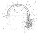
- FIG. 1 is a cross-sectional view showing a sweat rate measuring device 1 and a sweat rate measuring system 9 according to a first embodiment.
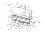
- 1 is a perspective view of the sweat rate measuring device 1 for explaining the flow of the internal air IA when the fan 30 is operating.
- FIG. 1 is a cross-sectional view of the sweat rate measuring device 1 for explaining the flow of the internal air IA when the fan 30 is operating.
- FIG. 4 is a diagram for explaining an internal space 57 in which a second temperature and humidity sensor is disposed in the first embodiment.
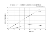
- FIG. 13 is a graph in which the integrated amount equivalent to the amount of head sweat is calculated by a thermal fluid simulation and plotted while changing the level by changing the placement location of the first temperature and humidity sensor 20.
- FIG. 2 is a block diagram showing an example of an electrical hardware configuration implemented in the sweat rate measuring device 1.
- FIG. FIG. 11 is a perspective view for explaining an internal air gathering structure 80 of a second embodiment.
- 11 is a diagram showing the function of the internal air collection structure 80 of the second embodiment for explaining the function of the internal air collection structure 80 of the second embodiment.
- FIG. 13 is a diagram for explaining an internal space 57a in which a second temperature and humidity sensor of embodiment 3 is arranged and an internal air collecting structure 80a.
- FIG. 13 is a diagram illustrating a sweat rate measuring device 5, 5' according to a fifth embodiment.
- FIG. FIG. 13 is a functional block diagram illustrating the main parts of a sweat rate measuring device 6 according to a sixth embodiment.
- FIG. 13 is a diagram illustrating an example of the configuration of a salinity concentration detection means 310 according to a sixth embodiment.
- 13 is a cross-sectional view showing a structure for realizing an internal space 57b in which a second temperature and humidity sensor according to Modification 1 is arranged.
- FIG. 7 is a perspective view showing a structure for realizing an internal space 57c in which a second temperature and humidity sensor according to Modification 2 is disposed.
- 13 is a diagram for explaining an internal space 57d in which a second temperature and humidity sensor according to Modification 3 is arranged, and an internal air collecting structure 80b.
- FIG. 13A to 13D are diagrams illustrating sensor covers 50a, 50b, 50c, and 50d according to a fourth modified example.
- 13 is a cross-sectional view of a main part for explaining the location of the second temperature and humidity sensor 40 according to the fifth modified example.
- FIG. 1 is a cross-sectional view showing the perspiration rate measuring device 1 and the perspiration rate measuring system 9 according to the first embodiment.
- the perspiration rate measuring device 1 in FIG. 1 corresponds to a cross-sectional view of the perspiration rate measuring device 1 cut along an imaginary plane perpendicular to the rotation axis AX, which includes the first temperature and humidity sensor 20 and the second temperature and humidity sensor 40, but does not include the annular frame 34 (described later), as viewed along the arrow B in FIG. 2 (the same applies to the following FIGS. 3, 8(c), 13, 15(b), 16(d), and 17).
- FIG. 3, 8(c), 13, 15(b), 16(d), and 17 the same applies to the following FIGS. 3, 8(c), 13, 15(b), 16(d), and 17.
- FIG. 2 is a perspective view of the perspiration rate measuring device 1 for explaining the flow of the internal air IA when the fan 30 is operating.
- the sensor cover 50, the control unit 70, and the like are omitted.
- FIG. 3 is a cross-sectional view of the perspiration rate measuring device 1 for explaining the flow of the internal air IA when the fan 30 is operating.
- the perspiration rate measuring device 1 of embodiment 1 is attached to the edge 102 of a helmet 100, and is a device that measures the amount of perspiration from the head H of a wearer WR of the helmet 100.
- the sweat rate measuring device 1 is provided with a helmet attachment means (reference numeral omitted) for attaching the sweat rate measuring device 1 to the helmet 100.
- the sweat rate measuring device 1 is provided with a clip portion 92, which constitutes the helmet attachment means.
- the clip portion 92 includes a clip inner peripheral material 92a, a clip outer peripheral material 92b, and a clip side peripheral material 92c (see also FIG. 2).
- An opening 12 is provided on one side (the upper side in the figure) of the clip portion 92, and when an edge portion 102 (rear edge portion) of the helmet 100 is inserted into the opening 12, the edge portion 102 of the helmet 100 is sandwiched and fixed between the clip inner peripheral material 92a and the clip outer peripheral material 92b. In this way, the sweat rate measuring device 1 is attached to the helmet 100.
- the sweat rate measuring device 1 includes an air flow path 10, a first temperature and humidity sensor 20, a fan 30, and a second temperature and humidity sensor 40.
- the sweat rate measuring device 1 rotates the fan 30 to draw in air from the outside world E (external air OA) into the helmet 100, and circulates air containing water vapor emitted from the head H inside the helmet 100 (internal air IA) so that it is exhausted from the fan 30.
- the first temperature and humidity sensor 20 and the second temperature and humidity sensor 40 measure the air flowing into and flowing out of this spatial system.
- outside world E refers, in a broad sense, to the area outside the area surrounded by the outer shell 101 of the helmet 100 and the sweat rate measuring device 1 when the helmet 100 is attached with the sweat rate measuring device 1 and worn by a person.
- outside world E refers to the area on the opposite side of the outer shell 101 of the helmet 100 or the sweat rate measuring device 1, rather than the wearer WR side. In a narrow sense, it can also be said to be the area outside the space through which internal air IA (described below) flows.
- Air flow path 10 The air flow path 10 is a structural part through which air (internal air IA) containing water vapor emitted from the head H of the wearer WR flows.
- the air flow path 10 is surrounded by walls such as a clip inner peripheral material 92a, a clip outer peripheral material 92b, a clip side peripheral material 92c, and an inner wall 64 constituting the fan case 60 described later.
- the air flow path 10 has an opening 12 formed by one end of each of the clip inner peripheral material 92a and the clip outer peripheral material 92b.
- the internal space connected from the opening 12 to the exhaust port 62 of the fan case 60 constitutes the air flow path 10.
- the opening 12 is connected to an internal helmet air flow path 110, which is a space between the helmet 100 and the head H, and the internal air IA can be taken in from the opening 12.
- the first temperature and humidity sensor 20 is a sensor for measuring the amount of moisture X1 (sometimes referred to as absolute humidity X1 ) contained per unit volume of the outside air OA that becomes the inflowing air.
- the first temperature and humidity sensor 20 is disposed in a location open to the outside world E, and measures the temperature and relative humidity of the outside air OA taken in from a location on the opposite side of the air flow path 10 from the wearer WR.
- the first temperature and humidity sensor 20 is electrically connected to the control unit 70 by wire or wirelessly (see FIG. 6 ), and transmits the sensed measurement values to the control unit 70.
- the first temperature and humidity sensor 20 is disposed on the opposite side of the wearer WR from the air flow path 10 through which the internal air IA flows. Specifically, when the clip outer peripheral material 92b is used as a reference, the first temperature and humidity sensor 20 is disposed on the opposite side of the wearer WR.
- the first temperature and humidity sensor 20 may be exposed to the outside world E.
- the structure of the perspiration rate measuring device 1 can be simplified by eliminating the cover, and the weight of the perspiration rate measuring device 1 can be reduced.
- the first temperature and humidity sensor 20 is further covered with a sensor cover 50 so that the first temperature and humidity sensor 20 is less susceptible to the effects of radiant heat from the outside, particularly sunlight.
- the sweat rate measuring device 1 is provided with a sensor cover 50 that covers the first temperature and humidity sensor 20.
- the sensor cover 50 is provided with an outside air intake 52 located on the opposite side of the air flow path 10 from the wearer WR, approximately above the first temperature and humidity sensor 20.
- the first temperature and humidity sensor 20 is connected to the outside world E via the outside air intake 52, and can be said to be located in a location that is open to the outside world E.
- such an outside air intake 52 is less likely to be mixed with heat, water vapor, etc. emitted by the wearer WR. Therefore, outside air OA that is less affected by heat, water vapor, etc. emitted by the wearer WR can be taken in and directed at the first temperature and humidity sensor 20.
- a shielding member 94 having a communication portion 95 is provided between the air flow path 10 and the space in which the first temperature and humidity sensor 20 is disposed.
- the outside air OA is also forcibly sucked in from the space in which the first temperature and humidity sensor 20 is disposed through the communication part 95. Then, a flow of the outside air OA (flow that flows in from the outside air intake 52, passes near the first temperature and humidity sensor 20, and reaches the communication part 95) is generated in the space in which the first temperature and humidity sensor 20 is disposed.
- the perspiration rate measuring device 1 a flow of outside air OA can be achieved without installing a new fan, and the first temperature and humidity sensor 20 can be placed in the space 55 where the flow of outside air OA occurs, making the perspiration rate measuring device 1 a space-saving, small, and lightweight device that can measure the amount of perspiration more accurately and with higher precision.
- the sucked in outside air OA merges with the inside air IA near the communication part 95 in the air flow path 10, but by setting the flow rate of the merging outside air OA to a level that is small compared to the flow rate of the inside air IA (to a level where the impact is minimal), it is possible to perform practical sweat rate measurement.
- the outside air OA is configured to flow at a substantially constant volume near the first temperature and humidity sensor 20, so that even if a sudden, strong hot or cold breeze occurs in the outside world E, the first temperature and humidity sensor 20 can sense the outside air OA in an environment that is almost completely free of disturbances, allowing for more accurate and precise measurement of the amount of head sweat Y.
- the first temperature and humidity sensor 20 is disposed upstream of the communication section 95 and in the vicinity of the communication section 95 when focusing on the flow of the outside air OA.
- the first temperature and humidity sensor 20 is disposed in such a position, it becomes possible to measure the temperature and relative humidity in the vicinity of the communication section where the outside air OA is sucked in and collected, and the measurement value of the head sweat rate Y becomes more accurate.
- the fan 30 has a plurality of blades 33 and a fan case 60 that houses the plurality of blades 33 inside and has an intake port 61 and an exhaust port 62.
- the plurality of blades 33 rotate around the rotation axis AX to suck in internal air IA from the air flow path 10 through the suction port 61 and exhaust the internal air IA to the outside through the exhaust port 62.
- a so-called cross-flow fan can be used as the fan 30 of the first embodiment.
- the fan 30 is cut along a plane perpendicular to the rotation axis AX as shown in FIG. 3 and the cut surface is viewed, a number of blades 33 are arranged at equal intervals along the circumferential direction centered on the rotation axis AX.
- the blades 33 are inclined at a predetermined angle relative to the circumferential direction so as to be inclined forward in the rotation direction ROT.
- the blades 33 are long and strip-shaped.
- Each blade 33 is fixed by at least two (five in the illustrated example) annular frames 34, with one end fixed to one annular frame 34 and the other end fixed to another annular frame 34.
- the blades 33 and the annular frames 34 form an impeller 35.
- a shaft 36 is connected to one end and the other end of the impeller 35 via the annular frames 34.
- the shaft 36 arranged at one end (left side in the illustrated example) is connected to a fan motor 38, and the shaft 36 arranged at the other end (right side in the illustrated example) is received in a bearing 39.
- the fan body 37 consisting of the impeller 35 and the shaft 36 is housed in an internal space 60IN surrounded by the fan case 60 (excluding a part of the shaft).
- the fan case 60 is provided with an intake port 61 facing the air flow path 110 inside the helmet and an exhaust port 62 facing the outside world E.
- a curved surface portion 65 having a curved shape along the circumferential direction in which the blades 33 rotate is provided on the fan case inner wall 64 between the edge 61a of the intake port and the edge 62a of the exhaust port, and a straightening portion 66a (reference numeral 66 denotes a straightening plate) is further provided from the curved surface portion 65 to the edge 62a of the exhaust port.
- the inner surfaces of the side plate 68 and the blocking plate 67 called the blind plate also constitute the fan case inner wall 64.
- a number of vanes 33 are disposed adjacent to or within the airflow path 10 .
- the fan 30 (fan motor 38 ) is electrically connected to a control unit 70 (see FIG. 6 described later), and its rotation is controlled by a drive signal or drive power supplied from the control unit 70 .
- the fan motor 38 rotates, the torque of the motor is transmitted to the impeller 35 via the shaft 36, causing the impeller 33 to rotate around the rotation axis AX.
- the impeller 33 rotates in the forward direction, the internal air IA is captured between two adjacent impellers 33 (see FIG. 3), and the captured internal air IA flows to a position opposite the position where it was captured, crossing the vicinity of the rotation axis AX inside the impeller 35 (cross flow), and the internal air IA is eventually discharged to the outside from between two other impellers 33 toward the exhaust port 62.
- the fan 30 is configured to discharge the internal air IA in a direction intersecting the rotation axis AX (see the arrows indicated by IA or IAj in each drawing (where j is a natural number)).
- the fan 30 has the function of forcibly moving the air present in the spatial system consisting of the air flow path 10 and the air flow path 110 inside the helmet.
- the fan 30 is positioned so that when the sweat rate measuring device 1 is attached to the edge 102 of the helmet 100, the air discharged from the fan 30 is directed toward the area from the back of the head to the nape of the neck N of the wearer WR. With this configuration, the air discharged from the fan 30 hits the area from the back of the head to the nape of the neck of the wearer WR directly, providing a cool feeling to the wearer WR and lowering the body temperature, which actively contributes to the prevention of heatstroke.
- Second temperature and humidity sensor 40 is a sensor for measuring the amount of moisture X2 (sometimes referred to as absolute humidity X2 ) contained per unit volume of the indoor air IA, which is the air discharged by the fan 30.
- the second temperature and humidity sensor 40 is disposed midway through the flow of the indoor air IA generated by the operation of the fan 30, and measures the temperature and relative humidity of the indoor air IA.
- the second temperature and humidity sensor 40 is electrically connected to the control unit 70 by wire or wirelessly (see FIG. 6 ), and transmits the sensed measurement values to the control unit 70.
- the first temperature and humidity sensor 20 may be in a form in which the temperature sensor and humidity sensor are packaged together, or in a form in which the temperature sensor and humidity sensor are separate. Also, the first pressure sensor 75 of the fourth embodiment described below may be packaged together with the temperature sensor and/or humidity sensor. Similarly, the second temperature and humidity sensor 40 may also have sensors that sense different physical quantities integrated with each other or separate.
- Fig. 4 is a diagram for explaining the internal space 57 in which the second temperature and humidity sensor is arranged in the first embodiment.
- Fig. 4(a) is a perspective view showing only the essential parts from the edge 62a of the exhaust port of the fan case 60 to the middle of the airflow straightening section 66a in Fig. 2.
- Fig. 4(b) is an enlarged cross-sectional view of the area surrounded by the dashed line C in Fig. 3.
- the second temperature and humidity sensor 40 is disposed at a position upstream of the internal air IA as viewed from the edge 62a of the exhaust port.
- the second temperature and humidity sensor 40 is disposed inside the fan case 60, slightly recessed as viewed from the exhaust port 62 (see also Figures 1 to 3).
- a recess is provided that is recessed in the thickness direction from the inside of the straightening plate 66 of the fan case 60, and this recess is defined as the "internal space 57 in which the second temperature and humidity sensor is disposed.”
- the internal space 57 in which the second temperature and humidity sensor is disposed is defined from other parts by a sensor installation surface 58 that is substantially perpendicular to the thickness direction of the fan case 60 and a side wall 59 that rises from the sensor installation surface 58.
- the second temperature and humidity sensor 40 is disposed by being fitted into the recess formed as the internal space 57 in which the second temperature and humidity sensor is disposed.
- the second temperature and humidity sensor 40 has its bottom surface abutting the sensor mounting surface 58 and its sides facing the four lateral walls 59a to 59d, and only its top surface faces the interior of the fan case 60.
- the top surface of the second temperature and humidity sensor 40 and the surface constituting the rectifying section 66a form the same plane (creating a so-called "flush” state), as shown in FIG. 4(a).
- the sweat rate measuring device 1 can basically measure the head sweat rate Y using the principle of sweat rate measurement described in Non-Patent Document 2. However, the first embodiment is not limited to this.
- the sweat rate measuring device 1 measures the temperature t1 and relative humidity RH1 of the outside air OA, which is the air of the outside world E or equivalent air flowing into the internal-helmet air flow path 110, with the first temperature and humidity sensor 20 to calculate the amount of moisture per unit volume as the inflow moisture rate X1 , and measures the temperature t2 and relative humidity RH2 of the internal air IA generated in the internal-helmet air flow path 110 with the second temperature and humidity sensor 40 to calculate the amount of moisture per unit volume as the outflow moisture rate X2 , and calculates the head sweat rate Y, which is the amount of sweat from the head H, based on the inflow moisture rate X1 , the outflow moisture rate X2 , and the air volume F related to the exhaust of the internal air IA by the fan 30.
- the head sweat rate Y is calculated by subtracting the inflow moisture rate X1 from the outflow moisture rate X2 and multiplying this by the air volume F. Furthermore, the amount of whole body sweat can be estimated based on the calculated amount of head sweat Y.
- a measuring device for performing measurements based on this principle can maximize the action and effect of the sweat rate measuring device 1 according to embodiment 1.
- a measuring device having the configuration of the sweat rate measuring device 1 according to embodiment 1 can more accurately measure the head sweat rate or whole body sweat rate according to the above principle. Details regarding the calculation of the head sweat rate Y will be mentioned later in the [Example].
- Example of thermal fluid simulation The inventors have obtained new knowledge, through a thermal fluid simulation, about the position of the first temperature and humidity sensor 20 suitable for accurately measuring the head sweat rate, which will be described below.
- the fan exhausts the internal air in the helmet air flow path or the air flow path.
- the second temperature and humidity sensor grasps the temperature and relative humidity of the internal air to grasp the outflow moisture amount.
- the first temperature and humidity sensor grasps the temperature and relative humidity of the outside air (external air) flowing into the helmet to grasp the outflow moisture amount.
- the principle of calculating the head sweat amount (equivalent amount) Y is the principle of sweat amount measurement described in Non-Patent Document 2.
- the second temperature and humidity sensor is to be placed in an area inside the exhaust port through which the fan exhausts the internal air.
- the first temperature and humidity sensor as a first standard, it is placed in the air flow path inside the helmet or on the opposite side of the air flow path from the wearer. Specifically, it is assumed that it is placed on the outside of the helmet's outer shell.
- the first temperature and humidity sensor is placed inside the helmet near the inlet for external air (see Fig. 1 in Non-Patent Document 2).
- FIG. 5 is a graph plotting the integrated amount equivalent to the amount of head sweat calculated by thermal fluid simulation while changing the placement location of the first temperature and humidity sensor 20 to change the level. 5, the head sweat amount equivalent (integrated value) increased linearly over time in level 1. On the other hand, in level 2, the head sweat amount equivalent (integrated value) tended to increase over time, but the integrated value was saturated after a certain time.
- the graph for level 2 does not increase linearly. This is thought to be because the position of the first temperature and humidity sensor in level 2 is a position where outside air is taken in, but where heat and moisture emitted from the wearer's neck, forehead, etc. may also be mixed in, reducing the accuracy of the measurement of the equivalent head sweat amount.
- the head sweat equivalent increases linearly over time, and it was found that the placement of the first temperature and humidity sensor in Level 1 provided a value closer to the actual head sweat amount. From the above thermal fluid simulation results, it was confirmed that when constructing the sweat rate measuring device 1, it is preferable to follow Level 1 and place the first temperature and humidity sensor in the air flow path inside the helmet or on the opposite side of the air flow path from the wearer.
- the clip inner peripheral material 92a and clip outer peripheral material 92b of the perspiration rate measuring device 1 are curved to follow the curved shape of the edge 102 of the helmet (see, for example, Figs. 10(b) and 10(d) used in the explanation of the fifth embodiment described below).
- the control unit 70 including the battery (not numbered) is mounted at the rear of the fan case 60.
- FIG. 6 is a block diagram showing an example of the electrical hardware configuration implemented in the sweat rate measuring device 1. As shown in FIG. 6, the sweat rate measuring device 1 of the embodiment is electrically configured around a control unit 70.
- the control unit 70 is a computer and has a processor 71, a memory 72a and a storage 72b (collectively, the storage unit 72), a communication I/F (interface) 73, and an input/output I/F (interface) 74. These are connected to a bus BS.
- a battery BAT supplies power to the control unit 70.
- the communication I/F may include wireless communication means.
- the processor 71 operates based on the programs stored in the memory unit 72 and controls each part.
- the memory unit 72 also includes a non-volatile storage device (ROM, etc.), which stores a boot program executed by the processor 71 when the sweat rate measuring device 2 is started up, and programs that depend on the hardware of the control unit 70, etc.
- ROM non-volatile storage device
- the communication I/F 73 transmits and receives data to and from an external management device via wireless communication means (no symbol).
- the communication I/F 73 mediates the transmission and reception of data to and from an information terminal device 306 (such as a smartphone or PC) via a network NW, for example.
- the input/output I/F 74 is electrically connected to the first temperature and humidity sensor 20, the second temperature and humidity sensor 40, the fan 30, etc., and serves as an interface with these input/output devices.
- the processor 71 controls the rotation of the fan 30.
- the processor 71 calculates the head sweat rate Y based on information from the first temperature and humidity sensor 20 and the second temperature and humidity sensor 40 transmitted via the input/output I/F 74.
- the processor may also calculate the whole body sweat rate based on the calculated head sweat rate Y.
- the processor 71 controls data transmission and reception with an external management device via the communication I/F 73.
- the processor 71 can also operate to store data related to the calculated head sweat rate Y and the whole body sweat rate in the memory unit 72.
- the control unit 70 calculates the amount of moisture per unit volume as the inflow moisture amount X1 based on the temperature t1 and relative humidity RH1 of the outside air OA received from the first temperature and humidity sensor 20.
- the control unit 70 calculates the amount of moisture per unit volume as the inflow moisture amount X1 based on the temperature t1 and relative humidity RH1 of the outside air OA received from the first temperature and humidity sensor 20.
- the control unit 70 calculates the inflow moisture amount X1 using the following equations (1) and (2).
- equations (1) to (3) when subscript 1 is picked up and applied to any one of the terms e, t, RH, and X, subscript 1 is also picked up and applied to the other terms.
- subscript 2 when subscript 2 is picked up and applied to one term, subscript 2 is also picked up and applied to the other terms.
- the control unit 70 calculates the amount of moisture per unit volume as the outflow moisture amount X2 based on the temperature t2 [°C] and relative humidity RH2 [%] of the interior air IA received from the second temperature and humidity sensor 40. Specifically, the control unit 70 calculates the amount of moisture per unit volume as the outflow moisture amount X2 using the above formulas (1) and (2) assuming that the outflow moisture amount is X2 [g/ m3 ], the temperature of the interior air IA is t2 [°C], the relative humidity of the interior air IA is RH2 [ %], and the saturated water vapor pressure of the interior air IA is e2 [hPa].
- the control unit 70 calculates the head sweat rate Y [g/m3] using the following formula (3) based on the inflow moisture rate X1 [g/ m3 ], outflow moisture rate X2 [g/ m3 ] obtained by the above calculation, and the given (known) air volume F [ m3 /min] of the fan 30 .
- control unit 70 can estimate the amount of whole body sweating based on the obtained head sweating amount Y.
- the control unit 70 has an "inflow moisture amount calculation unit 214 (not shown)” that calculates the amount of moisture per unit volume as the inflow moisture amount X1 , an “outflow moisture amount calculation unit 216 (not shown)” that calculates the amount of moisture per unit volume as the outflow moisture amount X2 , and a “head sweat amount calculation unit 218" that calculates the head sweat amount Y based on the inflow moisture amount X1 , the outflow moisture amount X2 , and the air volume F related to the exhaust of the internal air IA by the fan 30.
- the control unit may also have a "whole body sweat amount calculation unit 210" that estimates the whole body sweat amount based on the calculated head sweat amount Y.
- the above-mentioned water inflow calculation unit, water outflow calculation unit, head sweat amount calculation unit, and whole body sweat amount calculation unit may all be included in the control unit 70 within the sweat amount measurement device, or some or all of them may be included in a management device outside the sweat amount measurement device.
- the temperature and humidity sensor on the inflow air side (corresponding to the first temperature and humidity sensor 20) is disposed around the inner edge of the helmet.
- the position of this sensor is a position where outside air is taken in, there is a possibility that heat and moisture emitted from the neck, forehead, chest, back, etc. of the wearer may also be mixed in from this position.
- the configuration of the perspiration rate measuring device described in Non-Patent Document 2 may be affected by the heat and moisture of the wearer, and there is room for improvement in terms of measuring the head perspiration rate more accurately.
- the first temperature and humidity sensor 20 is disposed in a location that is open (opened) to the outside world E, and measures the temperature and relative humidity of the air of the outside world E taken in from a location on the opposite side of the air flow path 10 from the wearer WR. Therefore, fresh outside air is taken in around the first temperature and humidity sensor 20, with reduced inclusion of heat and moisture emitted from the wearer WR's head, neck, forehead, chest, back, etc. As the first temperature and humidity sensor 20 senses such air, the effects of heat and moisture emitted from the wearer WR are reduced, allowing the head sweat rate Y to be measured more accurately.
- the vanes 33 rotate about the rotation axis AX to suck in the internal air IA in the air flow path 10 through the suction port 61 and exhaust the internal air IA to the outside through the exhaust port 62, and the fan 30 can circulate most of the internal air IA generated around the head H of the wearer WR inside the helmet.
- the second temperature and humidity sensor 40 is disposed midway through the flow of the internal air IA generated by the operation of the fan 30. This makes it possible to accurately sense the temperature t2 and relative humidity RH2 of the internal air IA, and more accurately measure the amount of head perspiration Y.
- the internal air IA1, IA2, IA3, and IA4 that flowed approximately parallel downward along the rear side of the helmet internal air flow path 110 are guided by the movement of the blades 33 while maintaining a parallel relationship as described above, and are discharged from the exhaust port 62 as indicated by the symbols IA1', IA2', IA3', and IA4'.
- the internal air IA flows smoothly from the upstream side of the fan 30 to the downstream side (the exhaust port 62 side) while maintaining a parallel relationship.
- the sweat rate measuring device 1 using the fan 30 of embodiment 1 does not stir the air with propeller-type blades like an axial flow fan, so the flow resistance of the internal air IA is small overall, and the air blowing efficiency per unit power is high (high air blowing efficiency).
- the fan 30 of the first embodiment has high airflow efficiency, so the required air volume can be ensured without increasing the rotation speed significantly, and the wind noise caused by the blades 33 and the operating noise of the fan motor 38 are not loud, reducing the sense of noise (quiet).
- the sweat rate measuring device 1 using such a fan 30 is very suitable as a wearable device worn near the ear.
- the fan 30 of embodiment 1 has high air blowing efficiency, the power consumption required to ensure the required air volume is less than that of an axial fan (low power consumption).
- the fan 30 of embodiment 1 is low power, for example, if the same battery is used to operate the fan, the fan 30 of embodiment 1 can be operated for a longer period before the battery runs out than an axial fan. Conversely, to ensure the same operating time, the fan 30 of embodiment 1 requires less power than an axial fan, so a small and lightweight battery will suffice.
- the sweat rate measuring device 1 according to the first embodiment can be widely attached to general helmets that do not have fans, and while having characteristics suitable for wearing on the head, it can measure the head sweat rate more accurately than conventional devices. Furthermore, this accurate measurement can be achieved with a relatively simple configuration without increasing the number of parts, such as the number of fans or sensors.
- the sweat rate measuring device described in Non-Patent Document 2 is configured with a dedicated helmet (helmet with fan) with a fan embedded in part of the outer shell, and there was a situation where a very large fan could not be introduced. For this reason, in the past, when the wearer WR sweats a lot in a short period of time, the fan could not keep up with the air exhaust, and the measurement could not keep up with the changes in sweating state, and there was room for improvement in terms of more accurate and precise measurement.
- the perspiration rate measuring device 1 is adapted to measure the amount of perspiration by being attached externally to a commercially available helmet.
- the fan 30 is also external to the helmet body, so there is a high degree of freedom in the selection of the fan. It is also possible to adopt a fan that is larger, has a larger air volume, and is more efficient than a fan built into the helmet. By appropriately adopting such a high-performance fan, even if the wearer WR sweats a large amount in a short period of time, it is possible to exhaust the internal air IA with sufficient capacity, and it is possible to perform measurements that quickly follow, for example, a sudden increase in the amount of perspiration. From this point of view, too, highly accurate and precise measurements can be expected.
- the exhaust port 62 In a fan 30 that exhausts the inside air IA in a direction intersecting the rotation axis AX, such as a cross-flow fan, the exhaust port 62 generally has a wide opening, making it easy for the outside air OA to flow back.
- the second temperature and humidity sensor 40 is arranged at a position upstream of the inside air IA as viewed from the edge 62a of the outlet (arranged at the back as viewed from the outlet 62). Therefore, even if a small amount of outside air OA enters through the outlet 62, the outside air OA is pushed back by the main flow of the inside air IA, so that the influence of the outside air OA does not reach the position of the second temperature and humidity sensor 40 (or the influence can be reduced). In this way, the perspiration rate measuring device 1 has a structure that is not easily affected by disturbances of the outside air OA blowing in from the outlet 62, and therefore it is possible to more accurately measure the amount of head sweat.
- the internal space 57 in which the second temperature and humidity sensor is arranged is partitioned by a sensor mounting surface 58 that is approximately perpendicular to the thickness direction of the fan case 60 and a side wall 59 that rises from the sensor mounting surface 58.
- the outside air OA does not enter the internal space 57 by crossing at least the sensor installation surface 58 and the side wall 59. Since the second temperature and humidity sensor 40 is placed in an environment surrounded by the sensor installation surface 58 and the side wall 59 and where the outside air OA is unlikely to enter, the sweat rate measuring device 1 is less susceptible to disturbances from the outside air OA blowing in from the outlet 62, and it becomes possible to measure the head sweat rate more accurately.
- the sides of the second temperature and humidity sensor 40 are surrounded by the four horizontal walls 59a to 59d so that they face each other, and only the top surface of the sensor faces the inside of the fan case 60 (where a large amount of internal air IA flows), making it particularly difficult for external air OA to get mixed in.
- the top surface of the second temperature and humidity sensor 40 and the surface that constitutes the rectifying section 66a are flush with each other. Therefore, the internal air IA flowing over the surface of the rectifying section 66a passes through the same plane with almost no steps, which reduces flow resistance and makes it possible to suppress energy loss and noise generation due to flow resistance.
- the sweat rate measuring device 1 is provided with a sensor cover 50 that covers the first temperature and humidity sensor 20. Because such a cover is provided, like a weather observation screen, it is possible to prevent radiant heat from the sun, the ground, buildings, etc., radiant heat and convective heat from the wearer, moisture (water vapor) emitted by the wearer, etc. from being directly transmitted to the first temperature and humidity sensor 20. Therefore, the first temperature and humidity sensor 20 can perform sensing while suppressing the direct effects of these heat, moisture, etc., and can measure the head sweat rate Y more accurately.
- the first temperature and humidity sensor 20 of the first embodiment is placed in a space where a flow of outside air OA occurs.
- the first temperature and humidity sensor 20 is always exposed to fresh outside air OA that is not affected by sweating from the human body due to heat generation. This allows the amount of head sweat Y to be measured more accurately.
- Sweat rate measuring system 9 according to embodiment 1 Returning to FIG. 1, the sweat rate measuring system 9 will be described.
- the sweat rate measuring device 1 and the helmet 100 can be combined to configure a sweat rate measuring system 9.
- the sweat rate measuring system 9 includes the helmet 100 and the sweat rate measuring device 1 according to the first embodiment attached to a rim 102 of the helmet 100.
- the helmet 100 may be a typical helmet that is commercially available, such as a work helmet commonly used in the construction industry.
- the helmet 100 has an outer shell 101, an intermediate covering member 103, a brim 104, etc.
- the outer shell 101 is a member that separates the outside world E from the head H of the wearer WR, and protects the head H from the outside world E.
- An air flow path 110 inside the helmet is formed between the outer shell 101 and the head H of the wearer WR.
- the intermediate covering member 103 is, for example, an inner belt, and supports the helmet 100 while keeping it in contact with the head.
- the intermediate covering member 103 has an opening, which allows water vapor and hot air to pass between the head H and the air flow path 110 inside the helmet.
- the sweat rate measuring system 9 can provide the same effect as the sweat rate measuring device 1 according to embodiment 1. By using such a sweat rate measuring system 9, the amount of head sweat can be measured more accurately, and more appropriate heat stroke countermeasures can be taken.
- the sweat rate measuring system 9 is configured using the sweat rate measuring device 1 according to embodiment 1.
- the sweat rate measuring system can also be configured using the sweat rate measuring device according to each embodiment described below or each modified example.
- Fig. 7 is a perspective view for explaining the internal air collection structure 80 of the second embodiment.
- Fig. 7 is a view corresponding to Fig. 4(a) and is a perspective view of the main part showing only the portion from the edge 62a of the outlet of the fan case 60 to the middle of the straightening section 66a.
- Fig. 8 is a view for explaining the function of the internal air collection structure 80 of the second embodiment.
- Fig. 8(a) is a front view of the perspiration rate measuring device 1 as seen from the outlet 62 side.
- the helmet 100 to which the perspiration rate measuring device 1 is attached and the head H of the wearer WR are indicated by two-dot chain lines.
- Fig. 8(b) is a perspective view corresponding to Fig. 7, and Fig. 8(c) is a cross-sectional view corresponding to Fig. 3.
- the sweat rate measuring device 2 according to the second embodiment basically has the same configuration as the sweat rate measuring device 1 according to the first embodiment, but differs from the sweat rate measuring device 1 according to the first embodiment in that an internal air collection structure 80 is provided (a difference).
- an internal air collecting structure 80 is provided inside the fan case 60 near the exhaust port 62, which is configured to mix and collect a portion of the internal air IA minor of the internal air (the sum of IA major and IA minor ) that is to be exhausted, as the internal air IA minor that has been flowing parallel to each other moves toward the exhaust port 62 (see Figures 7 and 8).
- the internal air collecting structure 80 two ribs 83a, 83c are provided in the air flow straightening portion 66a.
- the wall upstream of the internal air IA constitutes a guide wall 82 as an air guide.
- the surface of this guide wall 82 intersects with the direction in which the internal air IA flows from the upstream of the internal air collecting structure 80. Therefore, when the internal air IA flows from the upstream, a part of the internal air IA collides with the surface of the guide wall 82 at a certain angle and is guided in a certain direction.
- the surfaces of the two guide walls 82 belonging to the ribs 83a and 83c are configured to approach each other toward the edge 62a of the exhaust port, and the surfaces of the guide wall 82 converge toward the internal air collecting place COP.
- the second temperature and humidity sensor 40 is disposed near the place COP where the internal air is collected in the internal air collecting structure 80.
- the height of the guide walls 82 belonging to the ribs 83 a and 83 c is set to be sufficiently smaller than the height of the discharge port 62 .
- the parallel relationship mentioned above refers to the appearance when viewed from a direction perpendicular to the rotation axis AX. Therefore, depending on where the second temperature and humidity sensor 40 is placed downstream of the internal air IA, the temperature and humidity values obtained from the sensor will differ, and it may not be possible to sense temperature and humidity representative of the entire head H of the wearer WR.
- the sweat rate measuring device 2 has the above-mentioned internal air collection structure 80, and as shown in FIG. 8(b), the internal air IA1, IA2, IA3, etc. flowing from upstream are guided by the guide wall 82 and mixed together as they move toward the internal air collection point COP, and are collected into internal air having a temperature and humidity representative of the entire head H of the wearer WR.
- the second temperature and humidity sensor 40 is disposed near the internal air collection point COP, and senses the internal air IA based on the internal air representative of the entire head H, enabling more accurate measurement of head sweat rate.
- the height of the guide wall 82 of the internal air collecting structure 80 is set sufficiently smaller than the height of the exhaust port 62, so that the volume ratio of the internal air IA minor , which is related to the mixing and aggregation of the internal air IA1, IA2, IA3, etc., among the total internal air (the sum of IA major and IA minor ) flowing toward the exhaust port 62, can be made very small. Therefore, most of the internal air IA major flowing above the guide wall 82 (based on the surface of the straightening portion 66a) flows straight and is discharged without being affected by the internal air collecting structure 80, and in practice, an increase in the flow resistance of the internal air IA can be almost avoided. Therefore, the sweat rate measuring device 2 according to the second embodiment can maintain characteristics such as high airflow efficiency, quietness, and power saving while aiming at the accuracy of head sweat rate measurement.
- the configuration is basically the same as that of the sweat rate measuring device according to the previous embodiment. Therefore, the effects based on the common configuration can be achieved in the same way in this embodiment.
- Fig. 9 is a diagram for explaining the internal space 57a in which the second temperature and humidity sensor is disposed and the internal air collecting structure 80a according to the third embodiment.
- Fig. 9(a) is a perspective view of the main part corresponding to Fig. 7.
- Fig. 9(b) is a right side view of the internal space 57a in which the second temperature and humidity sensor is disposed and the internal air collecting structure 80a when viewed along the arrow D in Fig. 9(a).
- the sweat rate measuring device of the third embodiment basically has the same configuration as the sweat rate measuring device of the previous embodiments (sweat rate measuring devices 1 and 2), but differs from the previous sweat rate measuring device in that an internal space 57a in which the second temperature and humidity sensor is disposed and an internal air collection structure 80a are formed by providing a sloped groove 85 in the straightening plate 66.
- the straightening plate 66 of the third embodiment has a groove 85 on the inner surface (straightening portion 66a) that is as if it were dug in a slope shape.
- the groove 85 is formed so that the groove opening is wide and the depth is small upstream of the straightening portion 66a, and the groove opening is narrow and the depth is large downstream.
- the slope 85c of the groove 85 becomes deeper (i.e., the degree of digging) toward the exhaust port 62.
- a sensor mounting surface 58 is provided that is approximately perpendicular to the thickness direction of the fan case 60, and a side wall 59c is formed rising from the sensor mounting surface 58 (see FIG. 9B).
- Side walls 59a and 59b which are the side walls of the groove 85, are connected to the left and right of the side wall 59c.
- the sensor mounting surface 58 and the side walls 59a, 59b, and 59c form the "internal space 57a in which the second temperature and humidity sensor is disposed.”
- the second temperature and humidity sensor 40 is disposed inside the "internal space 57a in which the second temperature and humidity sensor is disposed," which is surrounded by the three side walls 59a, 59b, and 59c and is located upstream of the internal air as viewed from the edge 62a of the exhaust port. Therefore, as in the first embodiment, the device is less susceptible to disturbances caused by the outside air OA blowing in from the exhaust port 62, allowing for more accurate head sweat rate measurement.
- the groove walls 85a, 85b narrow toward the edge 62a of the exhaust port, and converge at the edge 62a of the exhaust port.
- the groove walls 85a, 85b form the guide wall 82' as an air guide described in embodiment 2, and together form the internal air collection structure 80a.
- the second temperature and humidity sensor 40 is positioned near the location COP where the internal air is collected, and senses the internal air IA based on the internal air that represents the entire head H, allowing for more accurate head sweat measurement.
- this embodiment basically has the same configuration as the sweat rate measuring device according to the previous embodiment. Therefore, the effects based on the common configuration can be achieved in the same way in this embodiment.
- the sweat rate measuring device according to the fourth embodiment basically has the same configuration as the sweat rate measuring device according to the previous embodiment, but differs from the previous embodiment in that it further includes a pressure sensor.
- Air volume F related to exhaust of internal air IA by fan 30 In the above embodiment, it has been described that the calculation of a typical head sweat amount Y is based on the outflow moisture amount X2 , the inflow moisture amount X1 , and the air volume F related to exhaust of internal air IA by fan 30.
- the air volume F is a fixed value calculated backward from the capacity specifications of fan 30 and fan motor 38, the operating conditions of fan 30 (rotation speed during operation, etc.), the specifications of air flow path 10 in which fan 30 is placed, and the internal space 60IN of the fan case, etc.
- the exhaust of internal air IA is a one-point concentrated type, so that treating the air volume F as a fixed value has little practical effect.
- fans 30 that exhaust internal air IA in a direction intersecting the rotation axis AX such as cross-flow fans, generally have a wide exhaust port 62 and high airflow efficiency, so the blades 33 do not need to rotate very fast. This results in a small air volume per unit area and a low wind speed, making it easy for external air OA to backflow (enter the interior). For this reason, they are easily affected by disturbances from the external air OA blowing in from the exhaust port 62.
- the wearer WR of the perspiration rate measuring device frequently changes posture, such as temporarily bending forward and then standing upright again, or moves between work locations.
- the wearer WR may also work on the upper floors of a building.
- temporary transient wind is generated around the head H of the wearer WR.
- the exhaust port 62 of the fan case 60 When such temporary transient wind enters the exhaust port 62 of the fan case 60, the exhaust of the internal air IA is temporarily impeded or the exhaust of the internal air IA is temporarily accelerated.
- the actual air volume F related to the exhaust of the internal air IA changes due to the influence of disturbances of the external air OA from the exhaust port 62.
- the sweat rate measuring device in the sweat rate measuring device according to the fourth embodiment, the air pressure of the outside air OA and the air pressure of the inside air IA are measured to determine the air volume Fp that reflects the influence of disturbances in the outside air OA described in the above item 1. 6 , the sweat rate measuring device according to the fourth embodiment further includes a first pressure sensor 75 and a second pressure sensor 76 in addition to the sweat rate measuring devices (sweat rate measuring devices 1, 2, etc.).
- the first pressure sensor 75 is disposed in a location open to the outside world E, and measures the air pressure of the outside air OA.
- the second pressure sensor 76 is disposed near the second temperature and humidity sensor 40, and measures the air pressure of the inside air IA near the second temperature and humidity sensor 40.
- the first pressure sensor 75 is preferably disposed near the first temperature and humidity sensor 20. It is more preferable that the first pressure sensor 75 and the first temperature and humidity sensor 20 are packaged and configured as a single device. It is also more preferable that the second pressure sensor 76 and the second temperature and humidity sensor 40 are packaged and configured as a single device.
- the sweat rate measuring device of the fourth embodiment is configured to determine a flow velocity v of the internal air IA discharged from the air flow path 10 based on the difference between the pressure P1 obtained by the first pressure sensor 75 and the pressure P2 obtained by the second pressure sensor 76, determine an air volume Fp relating to the discharge of the internal air IA based on the flow velocity v and the cross-sectional area of the exhaust port 62 for the internal air IA, and calculate the amount of sweat Y from the head H based on the air volume Fp.
- the sweat rate measuring device has the above-described configuration, and even if there is a disturbance in the outside air OA near the outlet 62, the air volume Fp can be obtained according to the disturbance, so the head sweat rate Y can be accurately calculated.
- ⁇ represents the fluid density, which can be determined using the following equation (5) with ⁇ being the air density:
- t represents the temperature
- R represents the gas constant
- P atm represents the atmospheric pressure.
- the air volume Fp can be calculated by multiplying the flow velocity v by the cross-sectional area of the exhaust port 62 for the internal air IA.
- the configuration is basically the same as the sweat rate measuring device according to the previous embodiment. Therefore, the effects based on the common configuration can be achieved in the same way in this embodiment.
- FIGS. 10A and 10B are diagrams for explaining the sweat rate measuring devices 5 and 5' of the fifth embodiment.
- Fig. 10A is a front view of the sweat rate measuring device 5
- Fig. 10B is a right side view of the sweat rate measuring device 5.
- Fig. 10C is a front view of the sweat rate measuring device 5'
- Fig. 10D is a right side view of the sweat rate measuring device 5'.
- the sweat rate measuring device 5, 5' according to embodiment 5 basically has the same configuration as the sweat rate measuring device according to embodiments 1 to 3, but differs from the sweat rate measuring device according to embodiments 1 to 3 in that it further includes a flow sensor (a difference).
- a difference a difference
- the perspiration rate measuring device 5 further includes a first flow sensor 77 in addition to the perspiration rate measuring devices (perspiration rate measuring devices 1, 2, etc.) described above.
- the first flow sensor 77 is disposed at a location open to the outside world E, and measures the flow velocity of the outside air OA at that location.
- the first flow sensor 77 may be disposed, for example, in the vicinity of the exhaust port 62 of the fan case 60 and in the outer region of the flow straightening vane 66, as shown by the dashed line G1 in Fig. 10(a) .
- the first flow sensor 77 may be disposed in the vicinity of the exhaust port 62 and in the outer region of the side plate 68 of the fan case 60, as shown by the dashed line G2.
- the sweat rate measuring device 5 can be configured to obtain an air volume Ff relating to the exhaust of the internal air IA by correcting a predetermined air volume F calculated from the specifications of the fan 30 based on the flow velocity v1 obtained by the first flow sensor 77, and to calculate the amount of sweat from the head H based on the air volume Ff.
- a perspiration rate measuring device 5′ which is another embodiment of the fifth embodiment, further includes a first flow sensor 77 and a second flow sensor 78 in addition to the above-mentioned perspiration rate measuring devices (perspiration rate measuring devices 1, 2, etc.).
- the first flow sensor 77 is disposed at a location open to the outside world E, and measures the flow velocity of the outside air OA at that location.
- the first flow sensor 77 may be disposed near the exhaust port 62 of the fan case 60, in the outer region of the flow straightening vane 66, as shown in Fig. 10(b), for example.
- the first flow sensor 77 may be disposed at a position corresponding to the dashed line G2 in Fig. 10(a).
- the second flow sensor 78 is disposed near the second temperature and humidity sensor 40 and measures the flow speed of the inside air IA near the second temperature and humidity sensor 40 .
- the sweat rate measuring device 5′ can be configured to determine the flow velocity v of the internal air IA discharged from the air flow path based on the difference between the flow velocity v1 obtained by the first flow sensor 77 and the flow velocity v2 obtained by the second flow sensor 78, to determine the air volume Ff related to the discharge of the internal air IA based on the flow velocity v and the cross-sectional area of the internal air exhaust port 62, and to calculate the amount of sweat from the head H based on the air volume Ff.
- the sweat rate measuring device 5, 5' can accurately calculate the head sweat rate Y even if there is a disturbance in the outside air OA near the outlet 62, because the air volume Ff can be found in response to the disturbance.
- devices known in the market as MEMS flow sensors or MEMS flow rate sensors can be adopted as the first flow sensor 77 and the second flow sensor 78. Such sensors can detect even a slight change in air volume as a disturbance in the outside air OA, and are suitable for the first flow sensor 77 and the second flow sensor 78.
- the sweat rate measuring devices can also be used as devices that accurately and quickly predict the onset of heat stroke at a work site based on the acquired head sweat rate and other physiological information (multiple biological data based on other heat stroke onset mechanisms, such as whole-body sweat rate, whole-body salt loss, heart rate, and deep body temperature) and support the prevention of heat stroke onset.
- other physiological information multiple biological data based on other heat stroke onset mechanisms, such as whole-body sweat rate, whole-body salt loss, heart rate, and deep body temperature
- Fig. 11 is a functional block diagram of essential parts of the sweat rate measuring device 6 according to embodiment 6.
- All or a part of the functional blocks (e.g., whole-body sweat rate calculation unit 210, whole-body salt loss calculation unit 220, physiological information warning unit 250, heat stroke probability estimation unit 260, etc.) shown in Fig. 11 can be realized by a processor 71 of a control unit 70 and a program executed thereon.
- the sweat rate measuring device 6 of the first embodiment includes a head sweat rate calculation unit 208 that calculates the head sweat rate Y, a whole-body sweat rate calculation unit 210 that calculates the whole-body sweat rate based on the head sweat rate Y, and a physiological information warning unit 250 (see FIG. 11 ).
- the head sweat rate calculation unit 208 is a functional part that calculates the amount of sweat from the head (head sweat rate Y), and can utilize, for example, the configuration described in embodiments 1 to 5.
- the whole body sweat rate calculation unit 210 is a functional part that calculates the amount of whole body sweat based on the measured amount of sweat from the head (head sweat rate Y), and can utilize the configuration described in "3. Examples" of embodiment 1.
- the physiological information warning unit 250 issues a warning regarding physiological information (whole body sweat rate, whole body salt loss, heart rate, core body temperature, etc., as described below), and in the first embodiment, calculates the urgency of heat stroke countermeasures and/or the target amount of hydration based on the amount of whole body sweat, and outputs the calculated "urgency of heat stroke countermeasures" and/or "target amount of hydration” to the notification device 300.
- physiological information whole body sweat rate, whole body salt loss, heart rate, core body temperature, etc., as described below
- the physiological information warning unit 250 detects whether or not values related to physiological information are approaching or have become abnormal, and calculates the "risk of heat stroke countermeasures.” In addition, in relation to sweating and salt loss, it calculates a "target amount of hydration” and a “target amount of salt replenishment” that are strongly recommended for recovery. The physiological information warning unit 250 then warns a person (here, the wearer of the sweat rate measuring device 6 or the wearer's manager, etc.) via the notification device 300, presenting the "risk of heat stroke countermeasures," "target amount of hydration,” etc.
- the notification device 300 is an interface device that notifies a person of specific information.
- the notification device 300 can be configured with, for example, a voice generator, a display, and an information terminal device 306 such as a smartphone (see FIG. 6).
- the voice generator, display, and the like may be provided within the main body of the sweat rate measuring device 6, or may be provided as external components, for example, attached to the helmet 100.
- the warning regarding the "urgency of heat stroke prevention measures” may present a graded level of danger, such as "Take your next hydration or salt intake within 10 minutes,””Take a break within 5 minutes (while taking your next hydration or salt intake),” or “Stop working immediately and take a break (while taking your next hydration or salt intake),” or it may present a quantified level of danger according to certain rules.
- the "Target Amount of Hydration” warning displays a specific amount of water corresponding to the amount of whole body sweating, such as "Drink XX ml of water” or “Drink half a 500 ml plastic bottle of water.”
- the sweat rate measuring device 6 of the first aspect includes, in addition to the whole-body sweat rate calculating unit 210 described above, a heat stroke likelihood estimating unit 260 that estimates the likelihood of heat stroke.
- the heat stroke possibility estimation unit 260 estimates the possibility of heat stroke onset based on the amount of whole-body sweating, and outputs the estimated possibility of heat stroke onset to the notification device 300.
- a warning regarding the "possibility of developing heat stroke” may present a graded likelihood of developing heat stroke, such as "The risk of heat stroke is increasing (please take a break within 5 minutes),”"You are on the verge of developing heat stroke (please stop working and take a break immediately),” or “The situation is extremely dangerous (please take a break immediately while asking for help from those around you),” or it may present a numerical likelihood of developing heat stroke according to certain rules.
- the physiological information warning unit 250 and the heat stroke probability estimation unit 260 can output various warning information related to the above-mentioned "urgency of heat stroke countermeasures," “target amount of hydration,” “possibility of heat stroke,” etc., together with data such as the date and time when the warning information was issued and the destination, as electronic data to the memory unit 72 and record and store it as an electronic file.
- the electronic data can be output to the memory unit of the information terminal device 306 and recorded and stored as a file in the information terminal device 306 (especially the administrator's PC, etc.) (see also FIG. 6).
- the worker By configuring the first aspect of the sweat rate measuring device 6 as described above, the worker (the person wearing the device) can feel a sense of urgency because the worker (the person wearing the device) is informed of the "urgency of heat stroke countermeasures" and the "possibility of heat stroke onset” in concrete terms.
- the "target amount of hydration” is given as a numerical value, making it easier for the worker to take concrete action, thereby improving physical and mental safety.
- managers can issue specific instructions to workers to ensure their safety (especially instructions on heat stroke prevention and countermeasures), improving worker safety. Such safety instructions can also be recorded as electronic data and used for safety management.
- the sweat rate measuring device 6 of the second embodiment includes a salt concentration detecting means 310, a whole body salt loss calculating section 220, and a physiological information warning section 250 (see FIGS. 6 and 11).
- the salt concentration detection means 310 detects the salt concentration of the wearer.
- the salt concentration detection means 310 has a sweat detection probe 312 including a sensor that contacts the skin of the wearer and measures the electrical conductivity of the wearer's sweat, an electrical conductivity measurement unit 314 that receives an electrical signal detected by the sweat detection probe 312 and measures the electrical conductivity based on the electrical signal, and a salt concentration calculation unit 316 that calculates the salt concentration of the sweat based on the electrical conductivity output by the electrical conductivity measurement unit 314.
- the salt concentration detection means 310 supplies information on the salt concentration to the whole-body salt loss calculation unit 220, and the whole-body sweat rate calculation unit 210 supplies information on the whole-body sweat rate.
- a salt concentration measurement device described in JP 2021-32738 A can be used as the salt concentration detection means 310. It is also possible to apply a salt concentration measurement device having a different configuration, without being limited to these.
- the whole-body salt loss calculation unit 220 calculates the whole-body salt loss by performing calculations based on the sweat salt concentration information output by the salt concentration detection means 310 and the whole-body sweat rate information from the whole-body sweat rate calculation unit 210. Specifically, the real-time whole-body salt loss is obtained by integrating the real-time sweat salt concentration data and the real-time whole-body sweat rate data.
- the physiological information warning unit 250 calculates the urgency of heat stroke countermeasures and/or the target amount of salt replenishment based on the whole-body salt loss calculated by the whole-body salt loss calculation unit 220, and outputs the calculated “urgency of heat stroke countermeasures” and/or “target amount of salt replenishment” to the notification device 300.
- the warning regarding the "urgency of heat stroke countermeasures” is the same as that described in the first embodiment.
- the warning regarding the "target amount of salt replenishment” presents the specific amount of salt to be replenished corresponding to the amount of whole body salt loss, such as "Consume XX grams of salt” or "Drink 300 ml or more of a sports drink.”
- the sweat rate measuring device 6 of the second aspect is equipped with, in addition to the whole-body sweat rate calculation unit 210 described in the first aspect, a salt concentration detection means 310, a whole-body salt loss calculation unit, and a heat stroke probability estimation unit 260 described in the first aspect.
- the heat stroke possibility estimation unit 260 in the second aspect is configured to estimate the possibility of heat stroke onset based on the whole-body sweat rate and the whole-body salt loss rate, and output the estimated "possibility of heat stroke onset" to the notification device.
- the main difference from the first aspect is that the heat stroke possibility estimation unit 260 estimates the possibility of heat stroke onset by taking into account not only the whole-body sweat rate but also the whole-body salt loss rate.
- the warning regarding the "possibility of developing heat stroke" is as described in the first embodiment above.
- the second embodiment of the sweat rate measuring device 6 has a configuration that is basically the same as the first embodiment, and can achieve the same effects as the first embodiment.
- the sweat rate measuring device 6 of the third embodiment includes a heart rate detection means 320 and a physiological information warning section 250 (see FIGS. 6 and 11).
- the heart rate detection means 320 detects the wearer's heart rate.
- the heart rate detection means 320 can be a commercially available heart rate detection device, or a dedicated device can be installed in the sweat rate measurement device 6.
- the sweat rate measuring device 6 of the third aspect includes, in addition to the whole-body sweat rate calculation unit 210 described in the first aspect, a heart rate detection means 320 and the heat stroke probability estimation unit 260 described in the first aspect.
- the heat stroke possibility estimation unit 260 in the third aspect is configured to estimate the possibility of heat stroke based on the whole body sweat rate and the information output by the heart rate detection means 320, and output the estimated "possibility of heat stroke" to the notification device.
- the main difference from the first aspect is that the heat stroke possibility estimation unit 260 estimates the possibility of heat stroke by taking into account not only the whole body sweat rate but also the information output by the heart rate detection means 320.
- the warning regarding the "possibility of developing heat stroke" is as described in the first embodiment above.
- the third embodiment of the sweat rate measuring device 6 has a configuration that is basically the same as the first embodiment, and can achieve the same effects as the first embodiment.
- the sweat rate measuring device 6 of the fourth embodiment includes a deep body temperature detecting means 330 and a physiological information warning unit 250 (see FIGS. 6 and 11).
- the deep body temperature detection means 330 detects the body temperature of the wearer's deep body.
- the deep body temperature detection means 330 for example, the technology described in Patent Application No. 2023-222637, which was invented by the inventor and filed separately, can be appropriately adopted.
- the physiological information warning unit 250 calculates the urgency of heatstroke countermeasures and/or deep body temperature data based on the information output by the deep body temperature detection means 330, and outputs the calculated “urgency of heatstroke countermeasures” and/or “deep body temperature data” to the notification device 300.
- the warning regarding the "urgency of heat stroke countermeasures” is the same as that described in the first embodiment.
- the warning regarding the "core body temperature data” presents specific content corresponding to the information output by the core body temperature detection means 330, such as "core body temperature exceeds 40°C.”
- the sweat rate measuring device 6 of the fourth aspect is equipped with a deep body temperature detection means 330 and a heat stroke probability estimation unit 260 described in the first aspect, in addition to the whole-body sweat rate calculation unit 210 described in the first aspect.
- the heat stroke possibility estimation unit 260 in the fourth aspect is configured to estimate the possibility of heat stroke based on the amount of whole body sweat and the information output by the deep body temperature detection means 330, and output the estimated "possibility of heat stroke" to the notification device 300.
- the main difference from the first aspect is that the heat stroke possibility estimation unit 260 estimates the possibility of heat stroke by taking into account not only the amount of whole body sweat but also the information output by the deep body temperature detection means 330.
- the warning regarding the "possibility of developing heat stroke" is as described in the first embodiment above.
- the configuration that is basically the same as the first embodiment can achieve the same effects as the first embodiment.
- each aspect of the sixth embodiment can be combined and implemented. For example, it is possible to predict the onset of heat stroke based on another heat stroke mechanism from one physiological information (which can be said to be biological information).
- the heat stroke onset possibility estimation unit 260 can predict the onset of heat stroke by combining the physiological information obtained in each embodiment. In this way, it is possible to provide the wearer of the sweat rate measurement device with heat stroke onset prediction information more accurately, quickly, and precisely.
- the sweat rate measurement device 6 of each aspect can be attached to the edge 102 of the helmet 100 to form a sweat rate measurement system together with the helmet 100.
- FIG. 13 is a cross-sectional view showing the realization structure of the internal space 57b in which the second temperature and humidity sensor according to the first modification is disposed.
- FIG. 14 is an oblique view showing the realization structure of the internal space 57c in which the second temperature and humidity sensor according to the second modification is disposed, and is a perspective view of the main parts corresponding to FIG. 7.
- FIG. 15 is a view shown to explain the internal space 57d in which the second temperature and humidity sensor according to the third modification is disposed and the internal air collection structure 80b.
- FIG. 15(a) is a perspective view of the main parts corresponding to FIG. 7, and
- FIG. 15(b) is a cross-sectional view of the main parts corresponding to FIG. 3 as viewed from the D2 direction of FIG.
- FIG. 16 is a view shown to explain the sensor covers 50a, 50b, 50c, and 50d according to the fourth modification.
- FIGS. 16(a) to 16(c) are rear views of the sensor covers 50a, 50b, and 50c when viewed from the rear of the sweat rate measuring device.
- FIG. 16(d) is a cross-sectional view of the main parts shown to explain the sensor cover 50d.
- FIG. 17 is a cross-sectional view of a main part shown to explain the location of the second temperature and humidity sensor 40 according to the fifth modification.
- the "internal space 57 in which the second temperature and humidity sensor is disposed" is formed by a recess recessed in the thickness direction from the inside of the straightening plate 66, and the outside of the straightening plate 66 corresponding to the recess is flat, but the present invention is not limited to this. As shown in FIG. 13, the outside of the straightening plate 66 corresponding to the recess may be convex (Modification 1).
- the "internal space 57 in which the second temperature and humidity sensor is disposed” is a recess recessed in the thickness direction from the inside of the straightening plate 66, but the present invention is not limited to this.
- a tunnel-like structure may be formed by opposing side walls 59e, 59f rising from the sensor mounting surface 58 and a transition surface 59g connected to the side walls 59e, 59f and facing the sensor mounting surface 58, and the "internal space 57c in which the second temperature and humidity sensor is disposed” may be formed by such a tunnel-like structure. Note that the upstream and downstream sides of the tunnel-like structure for the internal air IAn are open, allowing the internal air IAn to flow without resistance (Modification 2).
- the ribs 83 and the slope-shaped grooves 85 are constructed to form the internal air collecting structures 80 and 80a.
- the present invention is not limited to this.
- a guide casing 87 as shown in FIG. 15 may be introduced, and the partition wall 87a of the guide casing 87 may be used as the guide wall 82''.
- the internal air IA minor is taken in through the wide opening of the inlet 87b of the guide casing 87, mixed and collected inside between the two partition walls 87a, and discharged from the outlet 87c.
- the vicinity of the outlet 87c is the "place COP where the internal air is collected.” It is preferable to set the vicinity of the terminal of the partition wall 87a as the side walls 59h and 59i, set the vicinity of the outlet 87c inside the guide casing 87 as the "internal space 57d where the second temperature and humidity sensor is disposed,” and install the second temperature and humidity sensor 40 in this space (Modification 3).
- the outside air OA is exhausted from the space 55 in the sensor cover 50 where the flow of the outside air OA occurs through the communication part 95, but the present invention is not limited to this.
- the sensor covers 50a to 50d may be configured to have an outside air outlet 53 in addition to the outside air intake 52 without using the communication part 95, so that the outside air OA is taken in from the outside air intake 52, flows near the first temperature and humidity sensor 20, and is exhausted from the outside air outlet 53.
- a sensor fan 54 is provided to forcibly generate a flow of the outside air OA (Modification 4).
- the second temperature and humidity sensor 40 has been described as being disposed inside the fan case 60.
- the present invention is not limited to this.
- the second temperature and humidity sensor 40 may be disposed immediately outside the exhaust port 62 of the fan case 60 (Variation 5). Even in this case, the second temperature and humidity sensor 40 is treated as being substantially "disposed midway in the flow of internal air" and the effects and advantages of the present invention can be achieved.
- perspiration rate measuring system 10... air flow path, 12... opening, 20... first temperature and humidity sensor, 30... fan, 33... blade, 34... annular frame, 35... impeller, 36... shaft, 37... fan body, 38... fan motor, 39... bearing, 40... second temperature and humidity sensor, 50, 50a, 50b, 50c, 50d... sensor cover, 52... external air intake port, 53... external air outlet port, 54... sensor fan, 55...
Landscapes
- Health & Medical Sciences (AREA)
- Life Sciences & Earth Sciences (AREA)
- Engineering & Computer Science (AREA)
- Heart & Thoracic Surgery (AREA)
- Public Health (AREA)
- Veterinary Medicine (AREA)
- Biophysics (AREA)
- Pathology (AREA)
- Physics & Mathematics (AREA)
- Biomedical Technology (AREA)
- General Health & Medical Sciences (AREA)
- Medical Informatics (AREA)
- Molecular Biology (AREA)
- Surgery (AREA)
- Animal Behavior & Ethology (AREA)
- Endocrinology (AREA)
- Gastroenterology & Hepatology (AREA)
- Physiology (AREA)
- Mechanical Engineering (AREA)
- General Engineering & Computer Science (AREA)
- Measuring And Recording Apparatus For Diagnosis (AREA)
Priority Applications (3)
| Application Number | Priority Date | Filing Date | Title |
|---|---|---|---|
| US18/865,787 US20250311964A1 (en) | 2023-03-04 | 2024-02-29 | Perspiration amount measuring device and perspiration amount measuring system |
| EP24767018.5A EP4678052A1 (en) | 2023-03-04 | 2024-02-29 | Perspiration amount measurement device and perspiration amount measurement system |
| JP2025505273A JPWO2024185648A1 (https=) | 2023-03-04 | 2024-02-29 |
Applications Claiming Priority (2)
| Application Number | Priority Date | Filing Date | Title |
|---|---|---|---|
| JP2023033262 | 2023-03-04 | ||
| JP2023-033262 | 2023-03-04 |
Publications (1)
| Publication Number | Publication Date |
|---|---|
| WO2024185648A1 true WO2024185648A1 (ja) | 2024-09-12 |
Family
ID=92675032
Family Applications (1)
| Application Number | Title | Priority Date | Filing Date |
|---|---|---|---|
| PCT/JP2024/007563 Ceased WO2024185648A1 (ja) | 2023-03-04 | 2024-02-29 | 発汗量計測装置及び発汗量計測システム |
Country Status (4)
| Country | Link |
|---|---|
| US (1) | US20250311964A1 (https=) |
| EP (1) | EP4678052A1 (https=) |
| JP (1) | JPWO2024185648A1 (https=) |
| WO (1) | WO2024185648A1 (https=) |
Cited By (2)
| Publication number | Priority date | Publication date | Assignee | Title |
|---|---|---|---|---|
| CN120608869A (zh) * | 2025-08-11 | 2025-09-09 | 歌尔股份有限公司 | 一种贯流风扇及头戴设备 |
| CN120650230A (zh) * | 2025-08-11 | 2025-09-16 | 歌尔股份有限公司 | 一种贯流风扇及头戴设备 |
Citations (5)
| Publication number | Priority date | Publication date | Assignee | Title |
|---|---|---|---|---|
| JPS62199811A (ja) * | 1986-02-25 | 1987-09-03 | 三洋電機株式会社 | 冷却装置付き帽子 |
| JP2019183373A (ja) * | 2018-03-30 | 2019-10-24 | 学校法人東京理科大学 | 衣服、熱中症予防システム及び水分補給警告システム |
| WO2020184686A1 (ja) * | 2019-03-13 | 2020-09-17 | 公立大学法人公立諏訪東京理科大学 | 頭部装着装置、熱中症予防システム及び水分補給警告システム |
| JP2021032738A (ja) | 2019-08-26 | 2021-03-01 | 公立大学法人公立諏訪東京理科大学 | 塩分濃度計測装置、頭部装着装置、及び塩分濃度計測方法 |
| JP2022064656A (ja) | 2020-10-14 | 2022-04-26 | トヨタ自動車株式会社 | 燃料電池の短絡検出方法 |
-
2024
- 2024-02-29 WO PCT/JP2024/007563 patent/WO2024185648A1/ja not_active Ceased
- 2024-02-29 EP EP24767018.5A patent/EP4678052A1/en active Pending
- 2024-02-29 JP JP2025505273A patent/JPWO2024185648A1/ja active Pending
- 2024-02-29 US US18/865,787 patent/US20250311964A1/en active Pending
Patent Citations (5)
| Publication number | Priority date | Publication date | Assignee | Title |
|---|---|---|---|---|
| JPS62199811A (ja) * | 1986-02-25 | 1987-09-03 | 三洋電機株式会社 | 冷却装置付き帽子 |
| JP2019183373A (ja) * | 2018-03-30 | 2019-10-24 | 学校法人東京理科大学 | 衣服、熱中症予防システム及び水分補給警告システム |
| WO2020184686A1 (ja) * | 2019-03-13 | 2020-09-17 | 公立大学法人公立諏訪東京理科大学 | 頭部装着装置、熱中症予防システム及び水分補給警告システム |
| JP2021032738A (ja) | 2019-08-26 | 2021-03-01 | 公立大学法人公立諏訪東京理科大学 | 塩分濃度計測装置、頭部装着装置、及び塩分濃度計測方法 |
| JP2022064656A (ja) | 2020-10-14 | 2022-04-26 | トヨタ自動車株式会社 | 燃料電池の短絡検出方法 |
Non-Patent Citations (2)
| Title |
|---|
| SEISAN KENKYU, STUDY ON THERMAL EVALUATION METHOD FOR HOT OUTDOOR ENVIRONMENT, vol. 58, 2006, pages 323 - 327 |
| TSUKASA KOSUDA: "Journal of Japan Institute of Electronics Packaging, General Incorporated Association", vol. 24, 2021, APAN INSTITUTE OF ELECTRONICS PACKAGING, article "Development of a Helmet Device Capable of Measuring Perspiration during Activity and Possibility of New Index for the Early Detection of Heat Stroke", pages: 541 - 550 |
Cited By (2)
| Publication number | Priority date | Publication date | Assignee | Title |
|---|---|---|---|---|
| CN120608869A (zh) * | 2025-08-11 | 2025-09-09 | 歌尔股份有限公司 | 一种贯流风扇及头戴设备 |
| CN120650230A (zh) * | 2025-08-11 | 2025-09-16 | 歌尔股份有限公司 | 一种贯流风扇及头戴设备 |
Also Published As
| Publication number | Publication date |
|---|---|
| US20250311964A1 (en) | 2025-10-09 |
| JPWO2024185648A1 (https=) | 2024-09-12 |
| EP4678052A1 (en) | 2026-01-14 |
Similar Documents
| Publication | Publication Date | Title |
|---|---|---|
| WO2024185648A1 (ja) | 発汗量計測装置及び発汗量計測システム | |
| JP6658822B2 (ja) | 集中度推定装置 | |
| US10495112B2 (en) | Low-noise blower | |
| JP5216519B2 (ja) | 空気調和機 | |
| JP6235007B2 (ja) | 蒸発式加湿器及びこれと同じものを有する屋内気候制御システム | |
| JPWO2024185648A5 (https=) | ||
| CN111247375A (zh) | 空调控制装置 | |
| JP6304502B2 (ja) | 空気調和機 | |
| JP6213744B2 (ja) | 空気調和機 | |
| JP2010091142A (ja) | 空気調和機 | |
| JP5422172B2 (ja) | 空気調和機 | |
| EP4417888A1 (en) | Air conditioning system, information processing device, and air conditioner control method | |
| CN106338105A (zh) | 吸气装置以及吸气方法 | |
| JP2025170282A (ja) | 発汗量計測装置及び発汗量計測システム | |
| JP2017020775A (ja) | 吸気装置および吸気方法 | |
| JP2010091159A (ja) | 空気調和機 | |
| US20130319081A1 (en) | Gas concentration meter | |
| CN108716473B (zh) | 一种轴流风扇和空调器室外机 | |
| CN111306726B (zh) | 空调器的控制方法、装置、空调器和电子设备 | |
| CN109115281A (zh) | 一种极端高温作业环境快速监测预警装置及方法 | |
| CN111336665B (zh) | 空调器的控制方法、装置、空调器和电子设备 | |
| Aynsley | Fan size and energy efficiency | |
| CN210599524U (zh) | 可自动调节风速的风扇 | |
| Singh et al. | Design and CFD analysis of ceiling fan for regular room size | |
| JP7734957B2 (ja) | 発汗量推定システム |
Legal Events
| Date | Code | Title | Description |
|---|---|---|---|
| 121 | Ep: the epo has been informed by wipo that ep was designated in this application |
Ref document number: 24767018 Country of ref document: EP Kind code of ref document: A1 |
|
| WWE | Wipo information: entry into national phase |
Ref document number: 2025505273 Country of ref document: JP |
|
| WWE | Wipo information: entry into national phase |
Ref document number: 2024767018 Country of ref document: EP |
|
| NENP | Non-entry into the national phase |
Ref country code: DE |
|
| WWP | Wipo information: published in national office |
Ref document number: 18865787 Country of ref document: US |
|
| ENP | Entry into the national phase |
Ref document number: 2024767018 Country of ref document: EP Effective date: 20251006 |
|
| ENP | Entry into the national phase |
Ref document number: 2024767018 Country of ref document: EP Effective date: 20251006 |
|
| ENP | Entry into the national phase |
Ref document number: 2024767018 Country of ref document: EP Effective date: 20251006 |
|
| ENP | Entry into the national phase |
Ref document number: 2024767018 Country of ref document: EP Effective date: 20251006 |