WO2024185222A1 - 吸収性物品 - Google Patents
吸収性物品 Download PDFInfo
- Publication number
- WO2024185222A1 WO2024185222A1 PCT/JP2023/041206 JP2023041206W WO2024185222A1 WO 2024185222 A1 WO2024185222 A1 WO 2024185222A1 JP 2023041206 W JP2023041206 W JP 2023041206W WO 2024185222 A1 WO2024185222 A1 WO 2024185222A1
- Authority
- WO
- WIPO (PCT)
- Prior art keywords
- absorbent
- nonwoven fabric
- thickness
- absorbent body
- sheet
- Prior art date
- Legal status (The legal status is an assumption and is not a legal conclusion. Google has not performed a legal analysis and makes no representation as to the accuracy of the status listed.)
- Ceased
Links
Images


Classifications
-
- A—HUMAN NECESSITIES
- A61—MEDICAL OR VETERINARY SCIENCE; HYGIENE
- A61F—FILTERS IMPLANTABLE INTO BLOOD VESSELS; PROSTHESES; DEVICES PROVIDING PATENCY TO, OR PREVENTING COLLAPSING OF, TUBULAR STRUCTURES OF THE BODY, e.g. STENTS; ORTHOPAEDIC, NURSING OR CONTRACEPTIVE DEVICES; FOMENTATION; TREATMENT OR PROTECTION OF EYES OR EARS; BANDAGES, DRESSINGS OR ABSORBENT PADS; FIRST-AID KITS
- A61F13/00—Bandages or dressings; Absorbent pads
- A61F13/15—Absorbent pads, e.g. sanitary towels, swabs or tampons for external or internal application to the body; Supporting or fastening means therefor; Tampon applicators
- A61F13/53—Absorbent pads, e.g. sanitary towels, swabs or tampons for external or internal application to the body; Supporting or fastening means therefor; Tampon applicators characterised by the absorbing medium
- A61F13/531—Absorbent pads, e.g. sanitary towels, swabs or tampons for external or internal application to the body; Supporting or fastening means therefor; Tampon applicators characterised by the absorbing medium having a homogeneous composition through the thickness of the pad
- A61F13/532—Absorbent pads, e.g. sanitary towels, swabs or tampons for external or internal application to the body; Supporting or fastening means therefor; Tampon applicators characterised by the absorbing medium having a homogeneous composition through the thickness of the pad inhomogeneous in the plane of the pad
- A61F13/533—Absorbent pads, e.g. sanitary towels, swabs or tampons for external or internal application to the body; Supporting or fastening means therefor; Tampon applicators characterised by the absorbing medium having a homogeneous composition through the thickness of the pad inhomogeneous in the plane of the pad having discontinuous areas of compression
-
- A—HUMAN NECESSITIES
- A61—MEDICAL OR VETERINARY SCIENCE; HYGIENE
- A61F—FILTERS IMPLANTABLE INTO BLOOD VESSELS; PROSTHESES; DEVICES PROVIDING PATENCY TO, OR PREVENTING COLLAPSING OF, TUBULAR STRUCTURES OF THE BODY, e.g. STENTS; ORTHOPAEDIC, NURSING OR CONTRACEPTIVE DEVICES; FOMENTATION; TREATMENT OR PROTECTION OF EYES OR EARS; BANDAGES, DRESSINGS OR ABSORBENT PADS; FIRST-AID KITS
- A61F13/00—Bandages or dressings; Absorbent pads
- A61F13/15—Absorbent pads, e.g. sanitary towels, swabs or tampons for external or internal application to the body; Supporting or fastening means therefor; Tampon applicators
- A61F13/53—Absorbent pads, e.g. sanitary towels, swabs or tampons for external or internal application to the body; Supporting or fastening means therefor; Tampon applicators characterised by the absorbing medium
- A61F13/534—Absorbent pads, e.g. sanitary towels, swabs or tampons for external or internal application to the body; Supporting or fastening means therefor; Tampon applicators characterised by the absorbing medium having an inhomogeneous composition through the thickness of the pad
- A61F13/535—Absorbent pads, e.g. sanitary towels, swabs or tampons for external or internal application to the body; Supporting or fastening means therefor; Tampon applicators characterised by the absorbing medium having an inhomogeneous composition through the thickness of the pad inhomogeneous in the plane of the pad, e.g. core absorbent layers being of different sizes
- A61F13/536—Absorbent pads, e.g. sanitary towels, swabs or tampons for external or internal application to the body; Supporting or fastening means therefor; Tampon applicators characterised by the absorbing medium having an inhomogeneous composition through the thickness of the pad inhomogeneous in the plane of the pad, e.g. core absorbent layers being of different sizes having discontinuous areas of compression
Definitions
- the present invention relates to absorbent articles such as disposable diapers.
- absorbent articles it is common to use an absorbent body made by mixing and aggregating pulp fibers and highly absorbent polymer particles, and in order to improve the shape retention during and after manufacturing, such absorbents are generally built into the absorbent element by wrapping a wrapping sheet made of crepe paper or the like around them (see, for example, Patent Documents 1 and 2).
- the absorbent element of an absorbent article is sandwiched between the legs and receives forces in various directions from both sides in the width direction due to leg movements such as walking, so while a good fit in the crotch area is required, shape retention is also required to prevent the absorbent body from losing its shape through kinking or cracking.
- the absorbent element of a disposable diaper is also required to ensure absorption performance in the crotch area.
- wrapping nonwoven fabric a finely woven nonwoven fabric
- wrapping nonwoven fabric there is a problem in that when the bottom of the grooves formed on the surface of the absorbent element is run over with a finger, the highly absorbent polymer particles give off a gritty feeling. If the user feels this gritty feeling, it can lead to a worsening wearing experience and a negative impact on the product's image, and this is undesirable.
- the main objective of the present invention is to prevent the gritty feel of the superabsorbent polymer particles from being transmitted to the user when using a wrapped nonwoven fabric.
- the absorbent article that solves the above problems is as follows:
- the garment has a crotch portion and a front portion and a rear portion extending forward and rearward from the crotch portion, an absorbent element having an absorbent body provided at a position including the crotch area and a wrapping nonwoven fabric wrapping the absorbent body;
- the absorbent body has a layer formed by mixing and accumulating pulp fibers and highly absorbent polymer particles,
- the absorbent element has a lattice-like continuous groove extending from the surface of the absorbent element to the absorbent body and having a bottom compressed in the thickness direction, The groove has an intersection portion and a non-intersection portion located between adjacent intersection portions, and in at least a part of the surface area of the absorbent element, the thickness of the bottom portion is gradually or continuously increased from the center of the non-intersection portion in the longitudinal direction toward the intersection portion.
- An absorbent article characterized by:
- the superabsorbent polymer particles are located at the bottom of the grooves, which is far from the skin, that is, at a location that is difficult for the user to touch directly or indirectly via another sheet, so that the sensation of the superabsorbent polymer particles is basically difficult for the user to feel.
- the packaging nonwoven fabric is pulled in two directions at the corners facing the intersections at the bottom of the grooves, making the corners particularly thin, and as a result, the intersections at the bottom of the grooves are more likely to come into direct or indirect contact with the skin than the non-intersections.
- the thickness of the bottom is gradually or continuously increased from the longitudinal center of the non-intersecting portion toward the intersecting portion (i.e., the degree of compression of the bottom is reduced from the longitudinal center of the non-intersecting portion toward the intersecting portion, and the density of the bottom is reduced), thereby suppressing the reduction in thickness of the corners facing the intersecting portions of the bottoms of the grooves, and making it difficult for the intersecting portions of the bottoms of the grooves to come into contact with the skin of the user. Therefore, compared to when the thickness of the bottoms of the grooves is almost constant, the gritty feeling of the superabsorbent polymer particles is not easily transmitted to the user.
- the basis weight of the pulp fibers in the absorbent body is 100 to 450 g/ m2 , the weight ratio of pulp fibers to superabsorbent polymer particles in the absorbent body is 30:70 to 70:30;
- the maximum thickness of the absorbent element is 4 to 35 mm; the thickness of the bottom portion at the longitudinal center of the non-intersecting portion is 15 to 35% of the maximum thickness of the absorbent element;
- the thickness of the bottom portion at the intersection is 1.4 to 6 times the thickness of the bottom portion at the center in the longitudinal direction of the non-intersection portion.
- the material composition of the absorbent body and the degree of compression of the bottom of the groove can be determined as appropriate, but it is preferable that they are within the range of this embodiment.
- ⁇ Third aspect> The width of the bottom is 1 to 3 mm;
- the grooves are formed in an oblique lattice shape including a first portion inclined at 40 to 50 degrees clockwise in a plan view with respect to the front-rear direction and a second portion inclined at 40 to 50 degrees counterclockwise in a plan view with respect to the front-rear direction.
- the dimensions and shapes of the grooves etc. can be appropriately determined, but when they are formed in a diagonal lattice pattern as in this embodiment, the absorbent body is excellent in shape retention and flexibility as well as in liquid diffusion, which is preferable. However, when the grooves are formed in the pattern of this embodiment, the thickness reduction at the corners facing the intersections of the bottoms of the grooves is particularly small, which is preferable.
- the packaging nonwoven fabric has one or more meltblown layers and one or more protective layers,
- the basis weight of the packaging nonwoven fabric is 10 to 17 g/ m2
- the constituent fibers of the protective layer have an average fiber diameter of 10 to 25 ⁇ m
- the constituent fibers of the meltblown layer have an average fiber diameter of 5 ⁇ m or less
- the air permeability measured in accordance with JIS L 1096:2010 using Method A (Fragile method) with five sheets of the packaging nonwoven fabric stacked together is 25.5 to 70.0 cm 3 /cm 2 ⁇ s;
- the packaging nonwoven fabric has a standard elongation rate in the front-rear direction, as defined in JIS L 1913:2010, of 20 to 100%,
- the standard elongation in the width direction as defined in JIS L 1913:2010 is 20 to 110%.
- the absorbent article according to any one of the first to third aspects.
- the wrapped nonwoven fabric is not easy to stretch, not only will it be difficult to form a firm groove, but the flexibility of the absorbent element will also decrease. Also, if the fiber structure of the wrapped nonwoven fabric is sparse, the superabsorbent polymer particles will easily slip out. Therefore, it is preferable to use a wrapped nonwoven fabric that is sufficiently thin and easy to stretch as in this embodiment, and that has a dense meltblown layer.
- the gritty feel of the superabsorbent polymer particles is likely to be transmitted to the user, but by having the above-mentioned characteristics (a) and (b), it is possible to improve the shape retention and flexibility of the absorbent body while suppressing the gritty feel of the superabsorbent polymer particles from being transmitted to the user.
- the breathability is also an index of the ease with which highly absorbent polymer particles can escape.
- the basis weight of the packaging nonwoven fabric is 15 to 17 g/ m2 ;
- the absorbent article of the fourth aspect is 15 to 17 g/ m2 ;
- the wrapping nonwoven fabric is not easy to stretch, not only will it be difficult to form a firm groove, but the flexibility of the absorbent element will also decrease. Also, if the fiber structure of the wrapping nonwoven fabric is sparse, the superabsorbent polymer particles will be easy to escape. Therefore, it is preferable to use a wrapping nonwoven fabric that is sufficiently thin and easy to stretch as in this embodiment, and that has a dense meltblown layer. These are as described above.
- the superabsorbent polymer particles may escape when the surface of the packaged nonwoven fabric is subjected to frictional force at the intersection of the grooves and its vicinity.
- the packaged nonwoven fabric is stretched in two directions (the direction intersecting with one adjacent groove and the direction intersecting with the other groove), making the thickness thinner than other parts and increasing the fiber gaps.
- the packaged nonwoven fabric of this embodiment by adopting the packaged nonwoven fabric of this embodiment and increasing the thickness of the bottom stepwise or continuously from the longitudinal center of the non-intersecting portion toward the intersecting portion (i.e., decreasing the degree of compression of the bottom from the longitudinal center of the non-intersecting portion toward the intersecting portion, and decreasing the density of the bottom), it is possible to suppress the expansion of the packaged nonwoven fabric on both sides of the groove and the resulting expansion of the fiber gaps and reduction in thickness from the longitudinal center of the non-intersecting portion toward the intersecting portion, compared to the case where this is not the case.
- the absorbent body has a covering layer in which only pulp fibers are accumulated and which covers the surface of the absorbent body.
- the absorbent article according to any one of the first to fifth aspects.
- the coating layer as in this embodiment is preferable because it makes it difficult for the highly absorbent polymer particles to escape from the surface of the absorbent body.
- the packaged nonwoven fabric has a back surface portion located on the back side of the absorbent body, a first front surface portion continuing from the back surface portion, wrapping around one side edge of the absorbent body to reach the front side of the absorbent body, and a second front surface portion continuing from the back surface portion, wrapping around the other side edge of the absorbent body to reach the front side of the absorbent body, the first front portion and the second front portion have laminated portions that overlap each other, All of the grooves are formed in the laminated portion.
- the absorbent article according to any one of the first to sixth aspects.
- the absorbent element has a middle portion, excluding both ends in the width direction, that is not covered by other members over the entire front-rear direction, and the wrapping nonwoven fabric is exposed on the surface of the absorbent article.
- the absorbent article according to any one of the fifth to seventh aspects.
- the present invention offers the advantage that, when using a wrapped nonwoven fabric, the gritty feel of the highly absorbent polymer particles is less likely to be felt by the user.
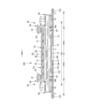
- FIG. 2 is a plan view showing the inner surface of the pants-type disposable diaper in an unfolded state.
- FIG. 2 is a plan view showing the outer surface of the pants-type disposable diaper in an unfolded state.
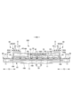
- This is a cross-sectional view of FIG.
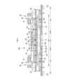
- FIG. 1A is a cross-sectional view taken along line 4-4 of FIG. 1
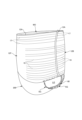
- FIG. 1 is a perspective view of a pants-type disposable diaper.
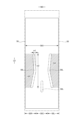
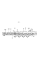
- FIG. 2 is a plan view showing the outer surface of the inner body in the deployed state together with the contour of the outer body.
- FIG. 2 is a plan view showing the surface of the absorbent body together with the outline of the packaging sheet.
- FIG. 2 is an enlarged view of a main portion of the surface of the absorbent element.
- (a) is a cross-sectional view taken along line 7-7 of FIG. 11, and (b) to (d) are cross-sectional views corresponding to the cross-section 7-7 of FIG.
- FIG. 2 is a cross-sectional view showing the absorbent element in a state before the absorbent body is wrapped in a wrapping sheet.
- FIG. 2 is a cross-sectional view showing the absorbent element in a state after the absorbent body is wrapped in a wrapping sheet and before the grooves are formed.
- FIG. 11 is a cross-sectional view of another absorbent element.
- FIG. 13 is a plan view of another absorbent element.
- FIG. 2 is a cross-sectional view of another example corresponding to cross section 2-2 of FIG. 1.
- 3 is a cross-sectional view of another example corresponding to cross section 3-3 of FIG. 1.
- FIG. 11 is a cross-sectional view of another absorbent element.
- FIG. 11 is a plan view showing another example of the absorbent body.
- 5A to 5C are schematic diagrams illustrating a method for manufacturing an absorbent element.
- FIG. 2 is a perspective view of a protrusion of the anvil roll.
- FIG. 1 is a schematic diagram of a test apparatus.
- FIG. 4 is an explanatory diagram of a friction pattern showing only the essential parts.
- a pants-type disposable diaper Each component adjacent in the thickness direction is fixed or joined as necessary in the same manner as known diapers, except for the fixed or joined parts described below.
- the dotted parts in the cross-sectional view indicate an adhesive such as a hot melt adhesive as the fixing or joining means.
- the hot melt adhesive can be applied by known methods such as slot application, continuous line or dotted line bead application, spiral, Z-shaped, wavy, etc. spray application, or pattern coating (transfer of hot melt adhesive using a letterpress method).
- the hot melt adhesive can be applied to the outer peripheral surface of the elastic member to fix the elastic member to the adjacent member.
- the hot melt adhesive for example, EVA-based, adhesive rubber-based (elastomer-based), polyolefin-based, polyester-polyamide-based, and other types are available, but they can be used without any particular limitations.
- a fixing or joining means for joining each component a material welding means such as heat sealing or ultrasonic sealing can also be used.
- adjacent components in the thickness direction are fixed or joined in an intermittent pattern. For example, when such intermittent fixing or joining is performed with a hot melt adhesive, intermittent pattern application in a spiral, Z-shape, wave shape, etc.
- Material welding means such as heat sealing and ultrasonic sealing can also be used as a joining means for joining each component.
- the constituent fibers of the nonwoven fabric can be selected without particular limitation from synthetic fibers such as polyolefins such as polyethylene or polypropylene, polyesters, polyamides, etc. (including single-component fibers as well as composite fibers such as core-sheath fibers), regenerated fibers such as rayon or cupra, natural fibers such as cotton, etc., and these can also be used in combination.
- synthetic fibers such as polyolefins such as polyethylene or polypropylene, polyesters, polyamides, etc. (including single-component fibers as well as composite fibers such as core-sheath fibers), regenerated fibers such as rayon or cupra, natural fibers such as cotton, etc., and these can also be used in combination.
- the constituent fibers are crimped fibers.
- constituent fibers of the nonwoven fabric can be hydrophilic fibers (including fibers that have been made hydrophilic by a hydrophilizing agent), hydrophobic fibers, or water-repellent fibers (including fibers that have been made water-repellent by a water-repellent agent).
- nonwoven fabrics are generally classified into staple fiber nonwoven fabrics, long fiber nonwoven fabrics, spunbond nonwoven fabrics, meltblown nonwoven fabrics, spunlace nonwoven fabrics, thermal bond (air-through) nonwoven fabrics, needle punch nonwoven fabrics, point bond nonwoven fabrics, laminated nonwoven fabrics (including SMS nonwoven fabrics and SMMS nonwoven fabrics in which a meltblown layer is sandwiched between spunbond layers), etc., depending on the fiber length, sheet formation method, fiber bonding method, and laminated structure, but any of these nonwoven fabrics can be used.
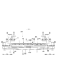
- This pants-type disposable diaper comprises a rectangular front outer body 12F constituting the front waist area, a rectangular rear outer body 12B constituting the rear waist area, and an inner body 200 provided inside the outer bodies 12F, 12B so as to extend from the front outer body 12F through the crotch area M to the rear outer body 12B.
- Both sides of the front outer body 12F and both sides of the rear outer body 12B are joined to form side seals 12A, whereby an opening formed by the front and rear ends of the outer bodies 12F, 12B becomes a waist opening WO through which the wearer's waist passes, and the portions on both widthwise sides of the inner body 200 that are surrounded by the lower edges of the outer bodies 12F, 12B and the side edges of the inner body 200 become leg openings LO through which the legs pass.
- the inner body 200 is a part that absorbs and retains excrement such as urine, and the outer bodies 12F and 12B are parts that support the inner body 200 against the wearer's body.
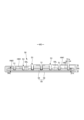
- the symbol Y indicates the total length of the diaper in the unfolded state when the front outer body 12F and the rear outer body 12B are not joined by the side seals 12A (the length in the front-to-rear direction from the edge of the waist opening WO of the front body F to the edge of the waist opening WO of the rear body B), and the symbol X indicates the total width of the diaper in the unfolded state.
- This pants-type disposable diaper has a waist region T defined as the front-to-back range having the side seal 12A (the front-to-back range from the waist opening WO to the upper end of the leg opening LO), and an intermediate region L defined as the front-to-back range of the portion forming the leg opening LO (between the front-to-back region having the side seal 12A of the front body F and the front-to-back region having the side seal 12A of the rear body B).
- the portions of the front outer body 12F and the rear outer body 12B located in the waist region T i.e., the front waist portion and the rear waist portion, can be conceptually divided into a "waist portion" W which forms the edge of the waist opening, and a “lower waist portion” U which is the portion below this.
- the waist portion W is the portion closer to the waist opening WO than the boundary closest to the waist opening WO, and when there is no such boundary, the waist extension portion 12E extending further toward the waist opening WO than the absorbent body 56 or the inner body 200 is the waist portion W.
- the length of these in the front-rear direction varies depending on the size of the product and can be determined appropriately, but as an example, the waist portion W can be 15 to 40 mm and the lower waist portion U can be 65 to 120 mm.
- both side edges of the middle region L are narrowed in a U-shape or curved shape to fit around the wearer's legs, and this is the portion where the wearer's legs are inserted.
- the pants-type disposable diaper in the unfolded state has a generally hourglass shape.
- the inner body 200 can have any shape, but in the illustrated example, it is a rectangle with the long sides forming both side edges. As shown in Figures 3 to 5, the inner body 200 comprises a top sheet 30 that faces the body, a liquid-impermeable sheet 11, and an absorbent element 50 interposed therebetween, and is a part that performs the absorption and retention functions.
- Reference numeral 40 denotes an intermediate sheet (second sheet) that is provided between the top sheet 30 and the absorbent element 50 in order to quickly transfer liquid that has permeated the top sheet 30 to the absorbent element 50
- reference numeral 60 denotes rising gathers 60 that extend from both sides of the inner body 200 so as to contact the wearer's legs in order to prevent excrement from leaking out to both sides of the inner body 200.
- the top sheet 30 is a material that has a property of being permeable to liquid, and examples of such material include a nonwoven fabric with or without holes, a plastic sheet with holes, etc.
- the top sheet 30 may be made of a single sheet, or may be made of a laminated sheet obtained by bonding two or more sheets together. Similarly, the top sheet 30 may be made of a single sheet, or may be made of two or more sheets in the planar direction.
- Both sides of the top sheet 30 may be folded back on the back side of the absorbent element 50 at the side edges of the absorbent element 50, or may not be folded back and extend out to the side beyond the side edges of the absorbent element 50.
- the overall width of the top sheet 30 may be made shorter than the overall width of the absorbent element 50, so that both side edges of the top sheet 30 are positioned on the absorbent element 50, and both sides of the surface of the absorbent element 50 are exposed on the surface of the diaper.
- the top sheet 30 is preferably fixed to the adjacent backside member by a joining means such as heat sealing or ultrasonic sealing that uses material welding, or by a hot melt adhesive, in order to prevent misalignment relative to the backside member.
- a joining means such as heat sealing or ultrasonic sealing that uses material welding, or by a hot melt adhesive
- the top sheet 30 is fixed to the surface of the intermediate sheet 40 and the surface of the portion of the packaging nonwoven fabric 58 that is located on the front side of the absorbent body 56 by a hot melt adhesive applied to its backside.
- an intermediate sheet (also called a "second sheet”) 40 that has a faster liquid permeability rate than the top sheet 30 can be provided.
- This intermediate sheet 40 is intended to quickly transfer liquid to the absorbent body, improve the absorption performance of the absorbent body 56, and prevent the "backflow" phenomenon of absorbed liquid from the absorbent body.
- the intermediate sheet 40 can also be omitted. In this case, the top sheet 30 can also be omitted.
- the intermediate sheet 40 examples include the same material as the top sheet 30, spunlace nonwoven fabric, spunbond nonwoven fabric, SMS nonwoven fabric, pulp nonwoven fabric, mixed sheet of pulp and rayon, point-bond nonwoven fabric, and crepe paper.
- air-through nonwoven fabric is preferred because it is bulky.
- the resin used for the core may be polypropylene (PP), but polyester (PET) with high rigidity is preferred.
- the basis weight is preferably 17 to 80 g/m 2 , and more preferably 25 to 60 g/m 2.
- the thickness of the raw fiber of the nonwoven fabric is preferably 2.0 to 10 dtex.
- eccentric fibers with no core in the center, hollow fibers, or eccentric and hollow fibers as the mixed fibers of all or part of the raw fiber.
- the intermediate sheet 40 is positioned in the center and is shorter than the width of the absorbent body 56, but it may be provided across the entire width.
- the length of the intermediate sheet 40 in the front-to-rear direction may be the same as the overall length of the diaper, the same as the length of the absorbent element 50, or within a short length range centered on the area that receives liquid.
- the intermediate sheet 40 is preferably fixed to the adjacent backside member by a material welding joining means such as heat sealing or ultrasonic sealing, or by a hot melt adhesive, in order to prevent misalignment relative to the backside member.
- a material welding joining means such as heat sealing or ultrasonic sealing
- a hot melt adhesive in order to prevent misalignment relative to the backside member.
- the intermediate sheet 40 is fixed to the surface of the portion of the packaging nonwoven fabric 58 located on the front side of the absorbent body 56 by a hot melt adhesive applied to the backside.
- the material of the liquid-impermeable sheet 11 is not particularly limited, but examples thereof include plastic films made of polyolefin resins such as polyethylene and polypropylene, laminated nonwoven fabrics in which a plastic film is provided on the surface of a nonwoven fabric, and laminated sheets in which a nonwoven fabric is layered and bonded to a plastic film. It is preferable to use a liquid-impermeable and moisture-permeable material that is preferably used from the viewpoint of preventing stuffiness for the liquid-impermeable sheet 11.
- a microporous plastic film obtained by kneading an inorganic filler into a polyolefin resin such as polyethylene or polypropylene, forming a sheet, and then stretching it in a uniaxial or biaxial direction is widely used.
- nonwoven fabrics using microdenier fibers nonwoven fabrics whose leak-proofing properties have been enhanced by reducing the gaps in the fibers through the application of heat or pressure, and sheets that have been made liquid-impermeable without using a plastic film by methods such as coating with a highly absorbent resin or a hydrophobic resin or a water repellent agent can also be used as the liquid-impermeable sheet 11, but it is preferable to use a resin film in order to obtain sufficient adhesive strength when bonded to the cover nonwoven fabric 13 described below via a hot melt adhesive.
- the liquid-impermeable sheet 11 is made to be wide enough to fit behind the absorbent element 50 as shown in the figure, but in order to improve leak-proofing, it can also be made to wrap around both sides of the absorbent element 50 and extend to both sides of the top sheet 30 of the absorbent element 50.
- the appropriate width of this extension is about 5 to 20 mm on each side.
- the absorbent element 50 has an absorbent body 56 and a wrapping nonwoven fabric 58 that wraps the entire absorbent body 56 .
- the absorbent body 56 is a mixture of pulp fibers and highly absorbent polymer particles.
- the basis weight of the pulp fibers can be, for example, about 100 to 450 g/ m2 .
- superabsorbent polymer particles includes not only “particles” but also "powders.”
- the superabsorbent polymer particles can be the same as those used in this type of disposable diaper. For example, it is desirable that the percentage of particles remaining on a 500 ⁇ m standard sieve (JIS Z8801-1:2006) when sieved (shaking for 5 minutes) is 30% by weight or less, and it is also desirable that the percentage of particles remaining on a 180 ⁇ m standard sieve (JIS Z8801-1:2006) when sieved (shaking for 5 minutes) is 60% by weight or more.
- Superabsorbent polymer particles include starch-based, cellulose-based and synthetic polymer-based materials, and examples of materials that can be used include starch-acrylic acid (salt) graft copolymers, saponified starch-acrylonitrile copolymers, crosslinked products of sodium carboxymethylcellulose and acrylic acid (salt) polymers.
- the shape of the superabsorbent polymer particles is preferably the commonly used powder-like form, but other shapes can also be used.
- the highly absorbent polymer particles preferably have a water absorption speed of 70 seconds or less, and particularly 40 seconds or less. If the water absorption speed is too slow, the liquid supplied to the absorbent body 56 tends to flow back out of the absorbent body 56, which is known as backflow.
- highly absorbent polymer particles with a gel strength of 1000 Pa or more are preferably used. This makes it possible to effectively suppress the sticky feeling after absorbing liquid, even when a bulky absorbent body 56 is used.
- the basis weight of the highly absorbent polymer particles can be appropriately determined according to the absorption amount required for the application of the absorbent body 56. Therefore, although it cannot be generally stated, it can be set to 50 to 350 g/ m2 . If the basis weight of the polymer is less than 50 g/ m2 , it becomes difficult to ensure the absorption amount. If it exceeds 350 g/ m2 , the effect becomes saturated.
- the ratio of pulp fibers and superabsorbent polymer particles in the absorbent body 56 is not particularly limited, and for example, the weight ratio of pulp fibers:superabsorbent polymer particles can be 40:60 to 65:35. In particular, a weight ratio of pulp fibers:superabsorbent polymer particles of 50:50 to 65:35 is preferable because the absorbent body 56 is excellent in shape retention, absorption speed, and ease of forming grooves 53 described below, and the risk of the superabsorbent polymer particles escaping is low.
- the superabsorbent polymer particles are present approximately uniformly throughout the absorbent body 56, but in order to prevent the superabsorbent polymer particles from escaping to the front side, it is preferable that the content of the superabsorbent polymer particles decreases stepwise or continuously from the back side to the front side, and in particular, as shown in FIG. 19, a covering layer 56c in which only pulp fibers are accumulated is provided so as to cover the surface of the absorbent body 56. Even when providing this covering layer 56c consisting of only pulp fibers, it is preferable that the ratio of fibers and superabsorbent polymer particles is within the above-mentioned range.
- the thickness 56t of the absorber 56 is not particularly limited, but can be, for example, 3 to 15 mm.
- the absorbent body 56 may extend across both the front and rear sides of the crotch area M to include the crotch area M. In the case of a pants-type disposable diaper such as this example, it is preferable that the absorbent body 56 extends to the peripheral edge of the inner body 200 or its vicinity in the front-rear direction LD and the width direction WD.
- the symbol 56X indicates the overall width of the absorbent body 56.
- the shape of the absorber 56 is approximately rectangular, as in the example shown in FIG. 8.
- the width n1 of the narrowest part of the absorber 56 in the crotch area M is 0.85 times or more the total width 56X of the absorber 56.
- the crotch region M means the range in the front-to-rear direction LD having the constricted portion 56n when the absorbent body 56 has the constricted portion 56n described below, or means the range in the front-to-rear direction LD having the constricted portion of the diaper's outer shape when the absorbent body 56 does not have the constricted portion 56n but has a constricted portion as in the illustrated example, or means the range in the front-to-rear direction LD having the constricted portion of the diaper's outer shape (between the front exterior body 12F and the rear exterior body 12B in the illustrated example) when there is no constricted portion, or means the portion located in the center in the front-to-rear direction LD whose dimension in the front-to-rear direction LD is 20-30% of the overall length of the product.
- the portions extending forward and backward from the crotch region M respectively become the front portion and the rear portion.
- the absorbent 56 may have elongated low basis weight portions 56L extending in the front-rear direction LD on both sides of the width direction WD in the crotch area M as shown in Figs. 8 and 20, or may not have low basis weight portions 56L as shown in Figs. 1 to 6.
- the low basis weight portions 56L refer to portions with a low basis weight, and do not include portions that are compressed in the thickness direction but do not change in basis weight, such as the bottoms 51 of the grooves 53 described later.
- the low basis weight portions 56L may be slits that penetrate in the thickness direction, but are preferably recesses with a low accumulation of pulp fibers and highly absorbent polymer particles as in the illustrated example, because this makes it easier to ensure the amount of absorption.
- the recesses may be formed on the front or back surface of the absorbent 56. Providing such low basis weight portions 56L in the absorbent 56 encourages the absorbent 56 to bend along the low basis weight portions 56L, improving the fit of the absorbent element 50 in the crotch area M.
- the total basis weight of the pulp fibers and superabsorbent polymer particles in the low basis weight portion 56L may be less than the total basis weight of the pulp fibers and superabsorbent polymer particles in the portions other than the low basis weight portion 56L, and may be, for example, 0.1 to 0.5 times the total basis weight of the pulp fibers and superabsorbent polymer particles in the portions other than the low basis weight portion 56L.
- the low-weighted portion 56L may extend linearly along the front-rear direction LD, or may be curved to be positioned to the side as it approaches both sides in the front-rear direction LD as in the illustrated example.
- the front and rear ends of the low-weighted portion 56L may be of any suitable shape, for example, a straight line as in the example shown in FIG. 20(a), a curved, bulging shape (semicircular arc, etc.) as in the example shown in FIG. 8, or a straight line with rounded corners at both ends (not shown).
- the width m1 of the low-weighted portion 56L may be set as appropriate, and may be, for example, 0.04 to 0.1 times the width n1 (meaning the overall width 56X in the case of a rectangle) of the narrowest part in the crotch portion M of the absorbent 56.
- the width m1 of the low-weighted portion 56L may be constant in its length direction or may vary.
- the dimensions and arrangement of the low-weighted portion 56L in the front-rear direction LD may be set as appropriate.
- the dimension m2 of the low weight portion 56L in the front-to-rear direction LD can be 50-120%, more preferably 50-80%, of the dimension of the crotch area M in the front-to-rear direction LD.
- the low weight portion 56L may be contained within the crotch area M, or may extend to the front, rear, or both front and rear sides of the crotch area M.
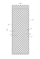
- the absorbent element 50 is preferably provided with a lattice-like continuous groove 53 having a bottom 51 that is recessed from the surface of the absorbent element 50 into the absorbent body 56 and compressed in the thickness direction.
- the bottom 51 of the groove 53 is a high-density portion that is compressed by pressing (direct pressure) and has a substantially uniform thickness.
- the portion other than the bottom 51 is referred to as a non-compressed portion 52.
- the non-compressed portion 52 is a portion that is thicker and has a lower density than the bottom 51, but even in the non-compressed portion 52, the absorbent body 56 and the packaging nonwoven fabric 58 are deformed as if pulled by the deformation of the bottom 51 near the bottom 51, so that the density increases as the non-compressed portion 52 approaches the bottom 51. As long as the non-compressed portion 52 is thicker and has a lower density than the bottom 51, the entire non-compressed portion 52 may be compressed in the thickness direction simultaneously with, before or after the compression process for forming the bottom 51.
- the shape and arrangement of the non-compressed portions 52 are determined according to the shape and arrangement of the bottom portion 51 .
- the bottom 51 at the longitudinal center of the non-intersecting portion 22 has a substantially constant first thickness t1
- the bottom 51 at the intersecting portion 21 has a substantially constant second thickness t2 that is thicker than the first thickness t1
- the portion between them is continuously thicker (sloping) from the first thickness t1 to the second thickness t2.
- the thickness of the bottom 51 is minimum (first thickness t1) at approximately the longitudinal center of the non-intersecting portion 22 and maximum (second thickness t2) at approximately the longitudinal center of the intersecting portion 21, and the thickness of the bottom 51 changes continuously in the longitudinal direction of the groove 53 (the bottom surface of the groove 53 has a sinusoidal or other wavy shape in a cross section along the longitudinal direction of the groove 53).
- first thickness t1 at approximately the longitudinal center of the non-intersecting portion 22
- second thickness t2 at approximately the longitudinal center of the intersecting portion 21
- the thickness of the bottom 51 changes continuously in the longitudinal direction of the groove 53 (the bottom surface of the groove 53 has a sinusoidal or other wavy shape in a cross section along the longitudinal direction of the groove 53).
- the thickness of the bottom 51 increases stepwise or continuously from the longitudinal center of the non-intersecting portion 22 toward the intersection portion 21 (i.e. the degree of compression of the bottom 51 decreases from the longitudinal center of the non-intersecting portion 22 toward the intersection portion 21, decreasing the density of the bottom 51), thereby suppressing a decrease in thickness of the corners of the non-compressed portion 52 facing the intersection portion 21 of the bottom 51 of the groove 53, and making it less likely that the intersection portion 21 of the bottom 51 of the groove 53 will come into contact with the user's skin. Therefore, compared to when the thickness of the bottom 51 of the groove 53 is approximately constant, the gritty feeling of the superabsorbent polymer particles is less likely to be transmitted to the user.
- the bottom thickness change region may extend over the entire area having the grooves 53 (i.e., all of the intersections 21 and non-intersections 22 may have the thickness change described above), or it may extend over only a part of the area having the grooves 53.
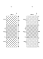
- the absorbent element 50 is divided into three areas 50C, 50L, and 50R in the width direction WD (e.g., divided into three equal parts) as shown in Figure 8 and a lattice-shaped groove 53 is formed over these three areas 50C, 50L, and 50R, it is preferable that at least the areas 50L and 50R on both sides are the bottom thickness change region described above.
- the thickness of the bottom 51 in the central region 50C has the first thickness t1 throughout the lattice-shaped grooves 53.
- the central region 50C is the bottom thickness change region described above, and with reference to the example of FIG.
- the grooves 53 in the regions 50L and 50R on both sides can be configured not to cross (not to have a recess (a portion compressed in the thickness direction) in the portion corresponding to the intersection 21), or the area of the unit frame 51f of the groove 53 in the regions 50L and 50R on both sides can be made larger (for example, 1.5 times or more) than the area of the unit frame 51f of the groove 53 in the central region 50C.
- the gritty feel of the superabsorbent polymer particles is particularly unlikely to be conveyed to the user, and the liquid diffusion in the width direction WD is low, making it difficult for side leakage to occur.
- the length 23L of the portion 23 having the second thickness t2 in the continuous direction XD of the groove 53 is preferably 0.3 to 1 times, and particularly preferably 0.5 to 0.9 times, the longitudinal dimension 22L of the non-intersecting portion 22.
- the length 24L of the portion 24 having the first thickness t1 in the continuous direction XD of the groove 53 is preferably 1 time or more, particularly preferably 1.1 times or more, the length 21L of the intersecting portion 21 in the continuous direction XD of the groove 53 (the distance between a pair of adjacent non-intersecting portions 22 sandwiching the intersecting portion 21), and less than 0.75 times the longitudinal dimension 22L of the non-intersecting portion 22.
- Such an absorbent element 50 can be manufactured by a known method such as embossing.
- the absorbent element 50 having the grooves 53 can be manufactured by carrying out the following three steps: a first step of forming an absorbent 56 made by mixing and accumulating pulp fibers and superabsorbent polymer particles; a second step of forming a package by wrapping the entire absorbent 56 in a package sheet 58; and a third step of passing the package 50P between an anvil roll 90 having a number of protrusions 91 arranged at intervals on the outer circumferential surface in the same pattern as the bottoms 51 of the grooves 53 and a smooth roll 92 having a cylindrical surface (without protrusions 91) facing the anvil roll 90, as shown in FIG.
- anvil roll 90 pressing the portion of the package 50P that is sandwiched between the many protrusions 91 of the anvil roll 90 and the smooth roll 92 to form a groove 53 having a bottom 51 compressed in the thickness direction.
- Either one or both of the anvil roll 90 and the smooth roll 92 may be pressed while being heated, or may be pressed without being heated.
- the third step only the portion of the package 50P that is sandwiched between the numerous protrusions 91 of the anvil roll 90 and the smooth roll 92 may be pressed, or the entire package 50P may be pressed while the portion that is sandwiched between the numerous protrusions 91 of the anvil roll 90 and the smooth roll 92 is pressed to the deepest depth.
- the pattern of the protrusions 91 of the anvil roll 90 is as shown in FIG. 22(a), and when forming the groove 53 of the example shown in FIG. 12(c), the pattern of the protrusions 91 of the anvil roll 90 is as shown in FIG. 22(b).
- the bottom 51 of the first thickness t1 is formed by pressing the first protrusion 91a
- the bottom 51 of the second thickness t2 is formed by pressing the second protrusion 91b.
- the inclined protrusion 91c connecting the first protrusion 91a and the second protrusion 91b forms the inclined bottom 51 connecting the bottom 51 of the first thickness t1 and the bottom 51 of the second thickness t2.
- the thickness 50t of the absorbent element 50 and the thickness 51t (t1, t2) of the groove bottom 51 can be determined as appropriate, but for example, the maximum value of the thickness 50t of the absorbent element 50 (maximum value of the thickness of the non-compressed portion 52) can be 4 to 35 mm, and is preferably 5 to 13 mm.
- the first thickness t1 of the bottom 51 can be determined as appropriate, but is usually preferably 15 to 35% of the maximum value of the thickness 50t of the absorbent element 50.
- the second thickness t2 of the bottom 51 is preferably 1.4 to 6 times the first thickness t1, and more preferably 2 to 4 times.
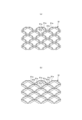
- One preferred pattern for the grooves 53 is a diagonal lattice pattern, as shown in the example in Figures 10 and 11, which is made up of first portions 51a extending in a direction inclined 40 to 50 degrees clockwise in plan view with respect to the front-to-rear direction LD, and second portions 51b extending in a direction inclined 40 to 50 degrees counterclockwise in plan view with respect to the front-to-rear direction LD.
- the shape of the unit frame 51f is approximately rhombus.
- the dimensions of the unit frame 51f can be determined as appropriate, but for example, the dimension 51x of the unit frame 51f in the width direction WD can be approximately 15 to 20 mm. Also, the dimension 51y of the unit frame 51f in the front-to-rear direction LD can be approximately 15 to 20 mm.
- the width 51w of the bottom 51 of the groove 53 can be determined as appropriate, but in normal cases it is preferably about 1 to 3 mm, and preferably approximately constant in the direction in which the groove 53 continues.
- the area ratio of the bottoms 51 of the grooves 53 to the surface of the absorbent element 50 can be determined as appropriate, but if the bottoms 51 of the grooves 53 are arranged too densely, the absorbent element 50 will become hard, so it is preferable to set it to about 10 to 14%.
- intersection 21 refers to the portion formed by connecting all the corners (the octagonal portion shown in the figure).
- intersection 21 refers to the portion formed by connecting the endpoints of the arcs that face each other across the groove.
- the area where the grooves 53 are continuous in a grid pattern may be the entire surface of the absorbent element 50 or a part of it.
- the grooves 53 are continuous in a grid pattern, liquid diffusion is improved, but if they are located at the front or rear end of the absorbent element 50, there is a risk of front or rear leakage. Therefore, as shown in FIG.
- the absorbent element 16(a) for example, it is preferable to divide the absorbent element into three parts: a middle region 50M in the front-to-back direction LD including the crotch area M, a region 50F further forward than this, and a region 50B further rearward, and to provide grooves 53 continuous in a grid pattern across all of these regions, and to make the area of the unit frame 51f in the front region 50F and the rear region 50B larger (for example, about 1.5 to 3 times larger) than the area of the unit frame 51f in the middle region 50M. Also, as shown in FIG.
- the nonwoven fabric 58 is preferably a nonwoven fabric having a meltblown layer formed of fibers with an average fiber diameter of 5 ⁇ m or less, and having an air permeability of 25.5 to 70.0 cm 3 /cm 2 ⁇ s measured in accordance with JIS L 1096:2010 (Fragile method) in a state where five sheets are stacked. It is more preferable that the air permeability of the nonwoven fabric 58 in a state where five sheets are stacked is 40.0 to 70.0 cm 3 /cm 2 ⁇ s. This air permeability can be measured, for example, using an air permeability measuring device (model AP-500KZ4) manufactured by Daiei Kagaku Seiki Seisakusho.
- the meltblown layer is a nonwoven fabric layer in which ultrafine fibers obtained by spinning a molten resin raw material into a high-speed hot gas flow are accumulated and the fibers are bonded to each other, and the average fiber diameter of the constituent fibers is as thin as 10 ⁇ m or less, the fiber length is 30 ⁇ m or more, and the fiber spacing is also small.
- the average fiber diameter of the fibers in the meltblown layer is preferably 2.5 ⁇ m or less.
- the average fiber diameter of the fibers in the meltblown layer can be 1 ⁇ m or more, and is preferably 2 ⁇ m or more.
- the total basis weight of the meltblown layer (if there are multiple meltblown layers, the sum of the basis weights of all layers) and the total thickness (if there are multiple meltblown layers, the sum of the thicknesses of all layers) can be appropriately determined.
- the total basis weight of the meltblown layer can be 0.3 to 6 g/ m2
- the total thickness of the meltblown layer can be 0.01 to 0.35 mm.
- the packaging nonwoven fabric 58 may be a single-layer nonwoven fabric consisting of only a meltblown layer, but a laminated nonwoven fabric having one or more meltblown layers and one or more protective layers is preferable.
- the laminated nonwoven fabric may be manufactured by stacking the webs that make up each layer in order and then bonding the fibers and each layer together by thermal bonding (point bonding, hot air bonding, etc.), or it may be manufactured by forming the nonwoven fabric layers that make up each layer individually (web formation and fiber bonding), stacking them, and bonding the layers together thermally or with an adhesive.
- a spunbond layer can be preferably used as the protective layer.
- a spunbond layer is a nonwoven fabric layer in which filaments obtained by extruding (spinning) molten resin raw material from a nozzle are accumulated and the fibers are bonded together.
- the average fiber diameter of the constituent fibers is larger than that of the meltblown layer, and the fiber length is also longer than that of the meltblown layer.
- an SMS nonwoven fabric, SSMMS nonwoven fabric, etc. in which at least one meltblown layer is sandwiched between a pair of spunbond layers on the front and back, can be preferably used.
- the material of the constituent fibers of each layer is not particularly limited, and for example, polypropylene fibers, polyethylene/polypropylene bicomponent fibers, etc. can be used for the meltblown layer, and polypropylene fibers, polyethylene/polypropylene bicomponent fibers, etc. can be used for the spunbond layer.
- the fiber diameter of the constituent fibers of the protective layer, the total basis weight (the sum of the basis weights of all layers when there are multiple protective layers), and the total thickness (the sum of the thicknesses of all layers when there are multiple protective layers) can be appropriately determined.
- the constituent fibers of the protective layer preferably have an average fiber diameter of 10 to 25 ⁇ m (particularly 15 to 20 ⁇ m).
- the total basis weight of the protective layer is preferably 5 to 17.5 g/m 2 (particularly 5 to 10 g/m 2 ), and the total thickness of the protective layer is preferably 0.01 to 0.35 mm (particularly 0.1 to 0.2 mm).
- the total basis weight of the wrapping nonwoven fabric 58 is preferably 10 to 17 g/m 2.
- the thickness of the wrapping nonwoven fabric 58 is preferably 0.2 to 0.8 mm.
- the wrapping nonwoven fabric 58 has a standard elongation rate in the front-rear direction LD of 20 to 100%, particularly 30 to 60%, as specified in JIS L 1913:2010, and a standard elongation rate in the width direction WD of 20 to 110%, particularly 50 to 70%, as specified in JIS L 1913:2010.
- the gritty feel of the highly absorbent polymer particles is likely to be conveyed to the user, but by having the aforementioned bottom thickness change region, it is possible to improve the shape retention and flexibility of the absorbent body 56 while suppressing the gritty feel of the highly absorbent polymer particles from being conveyed to the user.
- the packaging nonwoven fabric 58 when using a nonwoven fabric having one or more meltblown layers made of fibers with an average fiber diameter of 5 ⁇ m or less and one or more protective layers made of fibers with an average fiber diameter of 10 to 25 ⁇ m as the packaging nonwoven fabric 58 and the above-mentioned elongation rate, it is preferable to set the basis weight of the packaging nonwoven fabric 58 to 15 to 17 g/ m2 and to adopt the above-mentioned thickness change region of the bottom 51, because this makes it difficult for the superabsorbent polymer particles to escape to the outside of the packaging nonwoven fabric 58.
- the extension of the packaging nonwoven fabric 58 on both sides of the groove 53 and the resulting expansion of the fiber gaps and reduction in thickness can be suppressed from the longitudinal center of the non-intersecting portion 22 toward the intersecting portion 21, as compared with a case where this is not the case.
- the packaging structure of the packaging nonwoven fabric 58 can be determined as appropriate, but from the standpoint of ease of manufacture and prevention of leakage of superabsorbent polymer particles from the front and rear edges, it is preferable to wrap it around the front and rear surfaces and both sides of the absorbent body 56 in a cylindrical shape, as shown in the example shown, with the front and rear edges extending beyond the front and rear of the absorbent body 56, and to join the overlapping parts of the wrap and the overlapping parts of the protruding front and rear edges with a joining means such as a hot melt adhesive or material welding.
- the packaging nonwoven fabric 58 has a back portion 58s located on the back side of the absorbent body 56, a first front portion 58a that continues from the back portion 58s, wraps around one side edge of the absorbent body 56 to reach the front side of the absorbent body 56, and a second front portion 58b that continues from the back portion 58s, wraps around the other side edge of the absorbent body 56 to reach the back side of the absorbent body 56, and the first front portion 58a and the second front portion 58b have a stacked portion 58W where they overlap each other, and it is preferable that all the grooves are formed in the stacked portion 58W, because this can also prevent the superabsorbent polymer particles from escaping from the surface of the absorbent element 50.
- the absorbent element 50 may not have any other sheet layers such as paper or nonwoven fabric (which may of course have an adhesive layer) between the wrapping nonwoven fabric 58 and the absorbent body 56 as shown in FIG. 9, etc., or may have other sheet layers on at least one side of the front or back of the absorbent body 56.
- the rising gathers 60 have rising parts 68 that rise from the sides of the inner body 200, and these rising parts 68 come into contact with the wearer's groin, around the legs, and up to the buttocks to prevent side leakage.
- the rising gathers 60 have a base side part 60B that rises obliquely toward the widthwise center, and a tip side part 60A that rises obliquely from the intermediate part toward the widthwise outer side, but the present invention is not limited to this and can be modified as appropriate, such as one that rises toward the widthwise center as a whole.
- the rising gathers 60 in the illustrated example are formed by folding back a band-shaped gathered sheet 62 having a length equal to the front-rear length of the inner body 200 in the width direction WD at the tip portion and folding it in two, and fixing a plurality of elongated gather elastic members 63 at intervals in the width direction WD between the folded-back portion and the sheet in the vicinity of the folded-back portion in a stretched state along the longitudinal direction.
- the base end portion (the end portion opposite the folded-back portion of the sheet in the width direction WD) of the rising gathers 60 located opposite the tip portion is a root portion 65 fixed to the side of the inner body 200, and the portion other than the root portion 65 is a main body portion 66 (the portion on the folded-back portion side) extending from the root portion 65.
- the main body portion 66 also has a root portion 60B extending toward the center in the width direction and a tip portion 60A folded back at the tip of the root portion 60B and extending outward in the width direction.
- the front-rear direction ends of the main body portion 66 are fixed in a fallen state to the side surface of the top sheet 30 as fallen portions 67, while the front-rear direction intermediate portion between them is an unfixed raised portion 68, and a gathered elastic member 63 is fixed in a stretched state along the front-rear direction LD to at least the tip of this raised portion 68.
- the contractile force of the gather elastic member 63 causes the rise-up portions 68 to rise up and come into contact with the skin as shown by the arrows in FIG. 3.
- the rise-up portions 68 rise up to open outward in the width direction in the crotch area and its vicinity, so that the rise-up gathers 60 come into contact with the legs on a surface basis, improving the fit.
- the root portion 65 can also be fixed to the front side of the inner body 200, for example, to the surface of both sides of the top sheet 30.
- the tip portion 60A and the root portion 60B are joined in a fallen state at the fallen portion 67, and the root portion 60B is joined in a fallen state to the top sheet 30.
- the joining of the opposing surfaces at the fallen portion 67 can be performed using at least one of various application methods of hot melt adhesives and material welding such as heat sealing and ultrasonic sealing.
- the joining of the root portion 60B and the top sheet 30 and the joining of the tip portion 60A and the root portion 60B may be performed by the same means or by different means.
- a nonwoven fabric that is soft and has excellent uniformity and hiding properties such as spunbond nonwoven fabric (SS, SSS, etc.), SMS nonwoven fabric (SMS, SSMMS, etc.), or meltblown nonwoven fabric, which is treated with a water repellent treatment using silicone or the like as necessary, can be suitably used.
- the fiber weight of the nonwoven fabric is preferably about 10 to 30 g/ m2 .
- a waterproof film can be interposed between the gathered sheet 62 that is folded in two.
- the gathered elastic member 63 may be rubber thread or the like. When spandex rubber thread is used, the thickness is preferably 470-1240 dtex, more preferably 620-940 dtex. The elongation of the gathered elastic member 63 in the attached state is preferably 150-350%, more preferably 200-300%. The number of gathered elastic members 63 is preferably 2-6, more preferably 3-5. The appropriate spacing between the gathered elastic members 63 is 3-10 mm. With this configuration, the gathered elastic members 63 can easily come into contact with the skin in the area where they are arranged. The gathered elastic members 63 may be arranged not only on the tip side but also on the base side.
- At least one of various application methods of hot melt adhesive and material welding such as heat sealing and ultrasonic sealing can be used to bond the inner layer and outer layer of the gather sheet 62 together and to fix the gather elastic member 63 sandwiched between them. Since bonding the entire surfaces of the inner layer and outer layer of the gather sheet 62 together reduces flexibility, it is preferable that the parts other than the adhesive part of the gather elastic member 63 are not bonded or are weakly bonded.
- hot melt adhesive is applied only to the outer peripheral surface of the gather elastic member 63 by an application means such as a comb gun or a surwrap nozzle, and the gather elastic member 63 is sandwiched between the inner layer and the outer layer of the gather sheet 62, so that the gather elastic member 63 is fixed to the inner layer and the outer layer of the gather sheet 62 and the inner layer and the outer layer of the gather sheet 62 are fixed only by the hot melt adhesive applied to the outer peripheral surface of the gather elastic member 63.
- an application means such as a comb gun or a surwrap nozzle
- the fallen portion 67 can be fixed using at least one of a variety of application methods of hot melt adhesive and material welding such as heat sealing or ultrasonic sealing.
- side flaps 70 extending out to the sides of the absorbent body 56 are provided on both sides of the inner body 200, and it is preferable that side stretchable regions SG that stretch in the front-to-rear direction are formed in the side flaps 70.
- the side flaps 70 in the illustrated example have one or more elongated side elastic members 73 arranged along the front-to-rear direction LD and spaced apart from each other, a first sheet layer 71 facing the outside of the side elastic member 73, and a second sheet layer 72 facing the inside of the side elastic member 73.
- the sheet material constituting the first sheet layer 71 and the second sheet layer 72 is not particularly limited, and an appropriate nonwoven fabric can be selected, such as the nonwoven fabric that can be used in the above-mentioned rising gathers 60 and the above-mentioned exterior bodies 12F and 12B.
- the first sheet layer 71 and the second sheet layer 72 are formed by extending the gather sheet 62 of the rising gathers 60, as described below.
- the front and rear ends of the side flaps 70 coincide with the front and rear ends of the rising gathers 60 (i.e., in this case, the front and rear ends of the interior body 200).
- the side elastic members 73 are not particularly limited, and can be elongated elastic members similar to the gathered elastic members 63 described above.
- the extension rate of the side elastic members 73 in the attached state is preferably 150 to 350%, and more preferably 200 to 270%.
- the number of side elastic members 73 is preferably 2 to 16, and more preferably 6 to 10.
- the appropriate spacing between the side elastic members 73 is 5 to 10 mm.
- the side elastic member 73 is fixed to the first sheet layer 71 and the second sheet layer 72.
- Various application methods of hot melt adhesive HM and material welding such as heat sealing and ultrasonic sealing can be used to bond the first sheet layer 71 and the second sheet layer 72 together and to fix the side elastic member 73 sandwiched between them. If the bonding area of the first sheet layer 71 and the second sheet layer 72 is large, flexibility is lost, so it is preferable that the parts other than the adhesive part of the side elastic member 73 are not bonded or are weakly bonded.
- the hot melt adhesive HM is applied only to the outer peripheral surface of the side elastic member 73 by an application means such as a comb gun or a surwrap nozzle, and the side elastic member 73 is sandwiched between the first sheet layer 71 and the second sheet layer 72.
- the side elastic member 73 is fixed to the first sheet layer 71 and the second sheet layer 72 and fixed between the first sheet layer 71 and the second sheet layer 72 only by the hot melt adhesive HM applied to the outer peripheral surface of the side elastic member 73.
- the sheet material constituting the first sheet layer 71 and the sheet material constituting the second sheet layer 72 are folded back at the side edges of the side flaps 70, and these folded back portions are fixed (closed) to the back surface of the liquid-impermeable sheet 11.
- This fixing can be performed with hot melt adhesive HM as in the illustrated example, or by welding the materials.
- the side flaps 70 can also be omitted.
- the exterior bodies 12F, 12B are composed of a rectangular front exterior body 12F which is a part that constitutes at least the waist part of the front body F, and a rectangular rear exterior body 12B which is a part that constitutes at least the waist part of the back body B.
- the front exterior body 12F and the rear exterior body 12B may not be continuous on the crotch side and may be separated in the front-to-back direction LD (two-piece exterior type), or may be continuous from the front body to the back body (integrated exterior type) (not shown).
- the separation distance 12d in the front-to-back direction in the two-piece exterior type can be, for example, about 40 to 60% of the total length Y.
- the lower edges of the front exterior body 12F and the rear exterior body 12B are linear along the width direction WD, but at least one of the lower edges of the front exterior body 12F and the rear exterior body 12B may be curved so as to follow the leg circumference.
- the interior body 200 is exposed between the front exterior body 12F and the rear exterior body 12B. Therefore, in order to prevent the liquid-impermeable sheet 11 from being exposed on the rear surface of the interior body 200, it is preferable to provide a cover nonwoven fabric 13 on the rear surface of the interior body 200, which extends from between the front exterior body 12F and the interior body 200 to between the rear exterior body 12B and the interior body 200.
- the inner and outer surfaces of the cover nonwoven fabric 13 can be bonded to the opposing surfaces with a hot melt adhesive.
- the nonwoven fabric used for the cover nonwoven fabric 13 can be appropriately selected from the same material as the exterior bodies 12F and 12B, for example.
- the exterior body may be continuous from the front body F to the rear body B through the crotch area. In this case, the exterior body has not only a portion corresponding to the waist area T, but also a portion corresponding to the middle area L.
- the front exterior body 12F and the rear exterior body 12B have a front waist portion and a rear waist portion that form the waist region T.
- the dimensions of the front exterior body 12F and the rear exterior body 12B in the front-to-rear direction LD are equal, and the front exterior body 12F and the rear exterior body 12B do not have a portion corresponding to the middle region L, but as shown in Fig. 7, the front-to-rear dimension of the rear exterior body 12B is longer than that of the front exterior body 12F, and the front exterior body 12F does not have a portion corresponding to the middle region L, but the rear exterior body 12B may have a buttocks cover portion C extending from the waist region T to the middle region L side.
- the front exterior body 12F may also have a groin cover portion extending from the waist region T to the middle region L side.
- the outer body 12F, 12B is formed by joining an outer sheet layer and an inner sheet layer adjacent to the outer side and the inner side of the elastic members 16-19 described later, respectively, by a joining means such as a hot melt adhesive or welding.
- the outer sheet layer and the inner sheet layer can be formed from two sheets 12S, 12H as in the illustrated example, or from a single sheet material.
- the inner sheet layer and the outer sheet layer are respectively formed by the inner part and the outer part of a single sheet material folded back at the edge of the waist opening WO (which may be the edge on the crotch side) in part or all of the outer body 12F, 12B.
- the illustrated example is an example of the former, in which the sheet material 12S forming the outer sheet layer in the lower waist portion goes around the waist opening WO side of the sheet material 12H forming the inner sheet layer in the lower waist portion and is folded back to the inside of it, and this folded back part 12r extends so as to cover the end of the inner body 200 on the waist opening WO side. Meanwhile, in the waist area, the folded-back portion 12r forms an inner sheet layer adjacent to the inside of the elastic member.
- the exterior bodies 12F, 12B have built-in elastic members 16-19 to improve the fit around the wearer's waist, and a stretchable region A2 is formed that stretches elastically in the width direction WD with the stretching of the elastic members 16-19.
- the exterior bodies 12F, 12B contract with the contraction of the elastic members when in their natural length state, forming wrinkles or folds, and when stretched in the longitudinal direction of the elastic members, they can stretch to a predetermined stretch rate without wrinkles.
- the elastic members 16-19 can be long and thin elastic members such as rubber threads (illustrated example), as well as known elastic members such as strips, nets, films, etc., without any particular restrictions.
- the elastic members 16-19 can be synthetic or natural rubber.
- a plurality of waist elastic members 17 are attached to the waist portion W of the outer bodies 12F, 12B at intervals in the front-rear direction so as to be continuous over the entire width direction WD. Furthermore, one or more of the waist elastic members 17 arranged in the region adjacent to the lower waist portion U may overlap the inner body 200, or may be provided on both sides in the width direction except for the width direction central portion that overlaps with the inner body 200.
- the waist elastic member 17 is preferably made of 2 to 15, and more preferably 4 to 10 , rubber threads having a thickness of 155 to 1880 dtex, and especially 470 to 1240 dtex (in the case of synthetic rubber; in the case of natural rubber, a cross-sectional area of 0.05 to 1.5 mm2, and especially 0.1 to 1.0 mm2) spaced at intervals of 2 to 12 mm, and especially 3 to 7 mm, and the resulting elongation rate in the width direction WD of the waist portion W is preferably 150 to 400%, and especially 220 to 320%. It is not necessary for the waist portion W to use elastic members of the same thickness or to have the same elongation rate in all of its front-to-rear direction LD, and for example the thickness or elongation rate may be different in some parts.
- waist lower elastic members 16, 19 made of elongated elastic members are attached to the waist lower portion U of the exterior bodies 12F, 12B at intervals in the front-to-rear direction to form a waist lower stretchable region (region having waist lower elastic members 16, 19).
- the waist lower elastic members 16, 19 are preferably rubber threads having a thickness of 155 to 1880 dtex, particularly about 470 to 1240 dtex (in the case of synthetic rubber; cross-sectional area of 0.05 to 1.5 mm2 , particularly about 0.1 to 1.0 mm2 in the case of natural rubber), and are preferably provided at intervals of 1 to 15 mm, particularly about 3 to 8 mm, with an elongation rate of 200 to 350%, particularly about 240 to 300% in the width direction WD of the waist lower portion U. Furthermore, it is not necessary for the waist lower portion U to use elastic members of the same thickness or to have the same stretch rate all along the front-to-rear direction LD, and the thickness or stretch rate may be partially different.
- the widthwise middle including part or all of the part overlapping with the absorbent 56 in the width direction WD is a non-stretchable area A1, and both sides in the width direction are stretchable areas A2 (lower waist stretchable areas in the illustrated example).
- the widthwise dimension of the stretchable areas A2 provided on both sides of the non-stretchable area A1 is approximately constant in the front-to-rear direction LD as in the illustrated example, or can be changed in the front-to-rear direction LD, although not shown.
- the widthwise dimension of the stretchable areas A2 provided on both sides of the non-stretchable area A1 in the width direction WD can be approximately the same in the front body F and the back body B, or can be different.
- These stretchable regions A2 and non-stretchable regions A1 can be constructed by attaching elastic members 16-17, 19 between the inner sheet layer and the outer sheet layer, and then cutting the elastic members 16, 19 into small pieces by applying pressure and heat, or cutting, at one location in the middle of the width of the region that will become the non-stretchable region A1, or over almost the entire region, so that stretchability remains in the stretchable region A2 while eliminating stretchability in the non-stretchable region A1. Note that unnecessary elastic members 18 that do not substantially contribute to the formation of stretchability remain in the non-stretchable region A1.
- the sheet materials 12S, 12H forming the inner sheet layer and the outer sheet layer can be any material, but are preferably made of nonwoven fabric. When using nonwoven fabric, it is preferable that the weight per sheet is about 10 to 30 g/ m2 .
- the elastic members 16-19 can be fixed to the exterior bodies 12F, 12B by known methods.
- the inner sheet layer and the outer sheet layer can also be joined to each other by known methods.
- hot melt adhesive HM can be applied only to the outer peripheral surfaces of the elastic members 16-19 using an application means such as a comb gun or a surwrap nozzle, and the elastic members 16-19 can be sandwiched between the inner sheet layer and the outer sheet layer. This allows the elastic members 16-19 to be fixed to the inner sheet layer and the outer sheet layer, and the inner sheet layer and the outer sheet layer to be fixed, using only the hot melt adhesive HM applied to the outer peripheral surfaces of the elastic members 16-19.
- the inner body 200 can be joined to the outer bodies 12F, 12B by a joining means using material welding such as heat sealing or ultrasonic sealing, or by a hot melt adhesive.
- the inner body 200 is fixed to the inner surface of the outer bodies 12F, 12B via a hot melt adhesive applied to the back surface of the inner body 200, that is, in this case, the back surface of the liquid-impermeable sheet 11 and the root portion 65 of the rising gathers 60.
- the inner body joining portion 20 that joins the inner body 200 and the outer bodies 12F, 12B can be provided in almost the entire overlapping area as shown in FIG. 2, and can also be provided in a portion excluding both ends in the width direction of the inner body 200, for example.
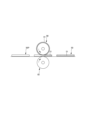
- the test device 80 is shown in FIG. 23.
- a recovery tray 83 for receiving a superabsorbent polymer is fixed on a shaking table 82b of a shaker 82 (MK161 manufactured by Yamato Scientific Co., Ltd.) installed on a horizontal surface 81, and a friction body 84 made of a metal cylinder (diameter 55 mm) is fixed upright in the center of the recovery tray 83, so that the recovery tray 83 and the friction body 84 are shaken together with the shaking table 82b.
- the vertical distance d1 between the upper surface of the friction body 84 and the upper surface of the shaking table 82b was 72 mm.
- a pair of pedestals 85 were fixed upright on both sides of the shaker 82 in the horizontal direction on the horizontal surface 81.
- the sample 86 was in an unfolded state (shown in FIG. 1), stretched between the pedestals 85 so that the surface of the sample 86 (the exposed surface of the packaging nonwoven fabric) was facing downward, and fixed to the pedestals 85.
- the front-rear direction LD of the sample 86 was set to the long axis direction BD of the ellipse of the shaking method.
- the vertical distance d2 between the friction body contact portion on the surface of sample 86 and the upper surface of shaking table 82b was set to 71 mm when friction body 84 was not installed so that the surface of sample 86 was in contact with friction body 84.
- the shaking method of shaker 82 was set to elliptical (swing width w1 in the major axis direction: 30 mm, shaking width w2 in the minor axis direction: 20 mm), and shaking was performed at a rotation speed of 90 rpm for 2 minutes. After rubbing against the surface of sample 86 by moving friction body 84 in an elliptical manner as shown in FIG. 24, the number of superabsorbent polymer particles that fell onto collection tray 83 was counted.
- Front-to-rear direction refers to the direction indicated by the symbol LD in the figure (longitudinal direction)
- width direction refers to the direction indicated by the symbol WD in the figure (left-to-right direction), with the front-to-rear direction and width direction being perpendicular to each other.
- Front side means the side closest to the wearer's skin when worn
- back side means the side furthest from the wearer's skin when worn
- Elongation rate refers to the value when the natural length is 100%. For example, an elongation rate of 200% is synonymous with an elongation ratio of 2 times.
- Gel strength is measured as follows. 1.0 g of superabsorbent polymer is added to 49.0 g of artificial urine and stirred with a stirrer. The resulting gel is left in a thermo-hygrostat at 40°C x 60% RH for 3 hours, then returned to room temperature and the gel strength is measured with a card meter (I.techno Engineering: Curdmeter-MAX ME-500).
- the "average fiber diameter” is determined by observing the target layer with a microscope (optical microscope, SEM, etc.) at 1000x magnification, randomly selecting 30 constituent fibers, measuring the fiber diameters ( ⁇ m), and calculating the average value.
- ⁇ "Balance weight is measured as follows. After pre-drying the sample or test piece, leave it in a test room or device under standard conditions (test location: temperature 23 ⁇ 1°C, relative humidity 50 ⁇ 2%) until it reaches a constant weight. Pre-drying refers to bringing the sample or test piece to a constant weight in an environment at a temperature of 100°C. Note that pre-drying is not necessary for fibers with an official moisture regain of 0.0%. Using a sample collection template (100mm x 100mm), cut out a sample measuring 100mm x 100mm from the test piece that has reached a constant weight. Measure the weight of the sample and multiply it by 100 to calculate the weight per square meter, which is the basis weight.
- the "thickness" of thick members such as the absorber 56, the absorbent element 50, and the bottom 51 of the groove 53 is measured using a thickness gauge from Ozaki Manufacturing Co., Ltd. (Peacock, dial thickness gauge, model J-B (measurement range 0-35 mm, measurement area 20 mm diameter circular terminal, measurement force approximately 3.0 N, pressure approximately 30 kPa)) with the sample and thickness gauge held horizontally.
- the "thickness" of a thin sheet such as a nonwoven fabric is automatically measured using an automatic thickness gauge (KES-G5 handy compression measurement program) under the conditions of a load of 0.098 N/cm 2 and a pressurized area of 2 cm 2. Note that the "thickness" of a packaged nonwoven fabric refers to the thickness of the portion where the thickness 50t of the absorbent element 50 is at its maximum value.
- the "layer thickness" of the nonwoven fabric is determined by observing the cross section of the target layer at the portion where the thickness 50t of the absorbent element 50 is at its maximum value using a microscope (optical microscope, SEM, etc.) at 1000x magnification, measuring the apparent thickness at five randomly selected measurement points, and calculating the average value.
- Area ratio means the ratio of the area of the target portion per unit area, and is expressed as a percentage by dividing the total area of the target portion (e.g., the bottom 51 of the groove 53) in the entire target region (e.g., the back surface of the absorbent element 50) by the area of the target region.
- the water absorption rate is the "time to the end point" when JIS K7224-1996 "Water absorption rate test method for superabsorbent polymers" is performed using 2 g of superabsorbent polymer and 50 g of physiological saline.
- “Expanded state” means a flat, unfolded state without contraction (including any contraction, such as contraction due to elastic members) or sagging.
- the dimensions of each part refer to the dimensions in the unfolded state, not the natural length.
- test or measurement shall be performed in a test room or device under standard conditions (the test location shall be a temperature of 23 ⁇ 1°C and a relative humidity of 50 ⁇ 2%).
- the present invention can be used for disposable diapers such as pants-type disposable diapers, tape-type disposable diapers, and pad-type disposable diapers, as well as sanitary napkins and other absorbent articles in general.
Landscapes
- Health & Medical Sciences (AREA)
- Epidemiology (AREA)
- Engineering & Computer Science (AREA)
- Biomedical Technology (AREA)
- Heart & Thoracic Surgery (AREA)
- Vascular Medicine (AREA)
- Life Sciences & Earth Sciences (AREA)
- Animal Behavior & Ethology (AREA)
- General Health & Medical Sciences (AREA)
- Public Health (AREA)
- Veterinary Medicine (AREA)
- Absorbent Articles And Supports Therefor (AREA)
Priority Applications (2)
| Application Number | Priority Date | Filing Date | Title |
|---|---|---|---|
| EP23926428.6A EP4555985A4 (en) | 2023-03-03 | 2023-11-16 | ABSORBENT ITEM |
| CN202380058014.6A CN119654122A (zh) | 2023-03-03 | 2023-11-16 | 吸收性物品 |
Applications Claiming Priority (2)
| Application Number | Priority Date | Filing Date | Title |
|---|---|---|---|
| JP2023032724A JP2024124805A (ja) | 2023-03-03 | 2023-03-03 | 吸収性物品 |
| JP2023-032724 | 2023-03-03 |
Publications (1)
| Publication Number | Publication Date |
|---|---|
| WO2024185222A1 true WO2024185222A1 (ja) | 2024-09-12 |
Family
ID=92674662
Family Applications (1)
| Application Number | Title | Priority Date | Filing Date |
|---|---|---|---|
| PCT/JP2023/041206 Ceased WO2024185222A1 (ja) | 2023-03-03 | 2023-11-16 | 吸収性物品 |
Country Status (5)
| Country | Link |
|---|---|
| EP (1) | EP4555985A4 (https=) |
| JP (1) | JP2024124805A (https=) |
| CN (1) | CN119654122A (https=) |
| TW (1) | TW202435828A (https=) |
| WO (1) | WO2024185222A1 (https=) |
Citations (7)
| Publication number | Priority date | Publication date | Assignee | Title |
|---|---|---|---|---|
| JPH08229070A (ja) * | 1994-12-28 | 1996-09-10 | Kao Corp | 体液吸収性物品 |
| WO2016185705A1 (ja) * | 2015-05-15 | 2016-11-24 | 王子ホールディングス株式会社 | 吸収性物品、その製造装置および製造方法 |
| JP6380454B2 (ja) | 2016-04-27 | 2018-08-29 | 王子ホールディングス株式会社 | 吸収性物品 |
| JP2020011113A (ja) * | 2016-02-12 | 2020-01-23 | 王子ホールディングス株式会社 | 吸収性物品 |
| JP2021000236A (ja) | 2019-06-20 | 2021-01-07 | ユニ・チャーム株式会社 | 吸収性物品、吸収体の製造方法、及び吸収体の製造装置 |
| JP2022137104A (ja) * | 2013-07-03 | 2022-09-21 | ディーエスジー テクノロジー ホールディングス リミテッド | 吸収複合材、吸収複合材を用いた吸収物品、並びに吸収複合材及び/又は吸収物品の製造方法、製造システム、及び製造装置 |
| JP2022190435A (ja) * | 2021-06-14 | 2022-12-26 | 大王製紙株式会社 | 使い捨ておむつ |
-
2023
- 2023-03-03 JP JP2023032724A patent/JP2024124805A/ja active Pending
- 2023-11-16 CN CN202380058014.6A patent/CN119654122A/zh active Pending
- 2023-11-16 WO PCT/JP2023/041206 patent/WO2024185222A1/ja not_active Ceased
- 2023-11-16 EP EP23926428.6A patent/EP4555985A4/en active Pending
-
2024
- 2024-01-31 TW TW113103649A patent/TW202435828A/zh unknown
Patent Citations (7)
| Publication number | Priority date | Publication date | Assignee | Title |
|---|---|---|---|---|
| JPH08229070A (ja) * | 1994-12-28 | 1996-09-10 | Kao Corp | 体液吸収性物品 |
| JP2022137104A (ja) * | 2013-07-03 | 2022-09-21 | ディーエスジー テクノロジー ホールディングス リミテッド | 吸収複合材、吸収複合材を用いた吸収物品、並びに吸収複合材及び/又は吸収物品の製造方法、製造システム、及び製造装置 |
| WO2016185705A1 (ja) * | 2015-05-15 | 2016-11-24 | 王子ホールディングス株式会社 | 吸収性物品、その製造装置および製造方法 |
| JP2020011113A (ja) * | 2016-02-12 | 2020-01-23 | 王子ホールディングス株式会社 | 吸収性物品 |
| JP6380454B2 (ja) | 2016-04-27 | 2018-08-29 | 王子ホールディングス株式会社 | 吸収性物品 |
| JP2021000236A (ja) | 2019-06-20 | 2021-01-07 | ユニ・チャーム株式会社 | 吸収性物品、吸収体の製造方法、及び吸収体の製造装置 |
| JP2022190435A (ja) * | 2021-06-14 | 2022-12-26 | 大王製紙株式会社 | 使い捨ておむつ |
Non-Patent Citations (1)
| Title |
|---|
| See also references of EP4555985A4 |
Also Published As
| Publication number | Publication date |
|---|---|
| CN119654122A (zh) | 2025-03-18 |
| JP2024124805A (ja) | 2024-09-13 |
| EP4555985A4 (en) | 2026-04-29 |
| TW202435828A (zh) | 2024-09-16 |
| EP4555985A1 (en) | 2025-05-21 |
Similar Documents
| Publication | Publication Date | Title |
|---|---|---|
| CN108601691B (zh) | 垫型一次性尿布 | |
| JP6479520B2 (ja) | 吸収性物品 | |
| TW200803802A (en) | Absorbent product | |
| US9149395B2 (en) | Liner for incontinence | |
| WO2015190547A1 (ja) | 吸収性物品 | |
| CN111356427B (zh) | 吸收性物品 | |
| JP7351630B2 (ja) | パンツタイプ使い捨て着用物品 | |
| CN107970092B (zh) | 短裤型一次性尿布 | |
| JP7476139B2 (ja) | 使い捨ておむつ | |
| JP6342765B2 (ja) | 使い捨て紙おむつ | |
| JP7315360B2 (ja) | パンツタイプ使い捨て着用物品 | |
| JP7774537B2 (ja) | 吸収性物品及びこれに用いる吸収要素の製造方法 | |
| WO2024185222A1 (ja) | 吸収性物品 | |
| EP4201386B1 (en) | Absorbent article | |
| WO2024070274A1 (ja) | 吸収性物品 | |
| JP2024124805A5 (https=) | ||
| JP2025075522A (ja) | 吸収性物品 | |
| JP2024048964A5 (https=) | ||
| JP7499661B2 (ja) | 吸収性物品 | |
| WO2024070276A1 (ja) | 吸収性物品及びこれに用いる吸収要素の製造方法 | |
| JP2025152377A (ja) | 使い捨ておむつ | |
| JP2021153716A5 (https=) | ||
| JP7519941B2 (ja) | 吸収性物品 | |
| WO2024195196A1 (ja) | パンツタイプ使い捨て着用物品 | |
| WO2024257440A1 (ja) | 使い捨ておむつ |
Legal Events
| Date | Code | Title | Description |
|---|---|---|---|
| 121 | Ep: the epo has been informed by wipo that ep was designated in this application |
Ref document number: 23926428 Country of ref document: EP Kind code of ref document: A1 |
|
| WWE | Wipo information: entry into national phase |
Ref document number: 2501000599 Country of ref document: TH |
|
| WWE | Wipo information: entry into national phase |
Ref document number: 202380058014.6 Country of ref document: CN |
|
| WWE | Wipo information: entry into national phase |
Ref document number: 2023926428 Country of ref document: EP |
|
| ENP | Entry into the national phase |
Ref document number: 2023926428 Country of ref document: EP Effective date: 20250213 |
|
| REG | Reference to national code |
Ref country code: BR Ref legal event code: B01A Ref document number: 112025004053 Country of ref document: BR |
|
| WWP | Wipo information: published in national office |
Ref document number: 202380058014.6 Country of ref document: CN |
|
| WWP | Wipo information: published in national office |
Ref document number: 2023926428 Country of ref document: EP |
|
| ENP | Entry into the national phase |
Ref document number: 112025004053 Country of ref document: BR Kind code of ref document: A2 Effective date: 20250228 |
|
| NENP | Non-entry into the national phase |
Ref country code: DE |