WO2024185083A1 - 通信システム - Google Patents
通信システム Download PDFInfo
- Publication number
- WO2024185083A1 WO2024185083A1 PCT/JP2023/008858 JP2023008858W WO2024185083A1 WO 2024185083 A1 WO2024185083 A1 WO 2024185083A1 JP 2023008858 W JP2023008858 W JP 2023008858W WO 2024185083 A1 WO2024185083 A1 WO 2024185083A1
- Authority
- WO
- WIPO (PCT)
- Prior art keywords
- communication
- wireless communication
- local wireless
- communication device
- platform
- Prior art date
- Legal status (The legal status is an assumption and is not a legal conclusion. Google has not performed a legal analysis and makes no representation as to the accuracy of the status listed.)
- Ceased
Links
Images






Classifications
-
- H—ELECTRICITY
- H04—ELECTRIC COMMUNICATION TECHNIQUE
- H04L—TRANSMISSION OF DIGITAL INFORMATION, e.g. TELEGRAPHIC COMMUNICATION
- H04L45/00—Routing or path finding of packets in data switching networks
- H04L45/24—Multipath
Definitions
- This disclosure relates to a communication system.
- the acquired data is sent to a mobile communication device inside the train via a platform communication device installed on the station platform.
- a wireless communication network is used in the communication path between the communication device in the platform and the mobile communication device.
- This wireless communication network can be a public wireless network that allows communication over the entire track, including inside the station, or a local wireless network that is built and operated by the railway operator.
- the home communication device and the mobile communication device can store the transmission method and communication state, allowing the home communication device and the mobile communication device to automatically select the appropriate wireless communication network.
- a method for managing the connection status of multiple predetermined wireless communication networks between a home communication device and a mobile communication device, and selecting a wireless communication network when a communication request occurs, but no specific method for checking the connection status is mentioned.
- one or more aspects of the present disclosure aim to switch the communication network used in railway vehicles from a public wireless network to a local wireless network, enabling reliable communication.
- the communication system is characterized by comprising: a public wireless communication device that wirelessly transmits target data, which is data to be transmitted to a railway vehicle, to the railway vehicle using a public communication network; a local wireless communication device that receives the target data from the public wireless communication device via a system communication path, at least a portion of which is wired, formed between the public wireless communication device and the railway vehicle, and transmits the target data to the railway vehicle using a local wireless communication method having a communication range that covers at least a portion of the platform of the railway vehicle; and a monitoring and control device that monitors whether the system communication path is sound and whether the local wireless communication path, which is a communication path using the local wireless communication method between the local wireless communication device and the railway vehicle, is sound, and when the railway vehicle enters the communication range, if both the system communication path and the local wireless communication path are sound, causes the local wireless communication device to transmit the target data, and if at least one of the system communication path and the local wireless communication path is not sound, causes the public wireless
- the communication network used in a railway vehicle can be switched from a public wireless network to a local wireless network, ensuring reliable communication.
- FIG. 1 is a block diagram illustrating a schematic configuration of a mobile communication system according to a first embodiment.
- FIG. 2 is a block diagram illustrating a schematic configuration of a monitoring and control device according to the first to third embodiments.
- FIG. 2 is a schematic diagram showing an example of communication path health information in the first embodiment.
- 1A and 1B are block diagrams showing an example of a hardware configuration.
- FIG. 1 is a block diagram illustrating a schematic configuration of a network switch.
- FIG. 2 is a block diagram showing a schematic configuration of a home communication device.
- FIG. 1 is a block diagram illustrating a schematic configuration of a local wireless communication device.
- FIG. 1 is a block diagram illustrating a schematic configuration of a mobile communication device.
- FIG. 4 is a sequence diagram showing the operation of the mobile communication system according to the first embodiment.
- FIG. 5 is a flowchart showing a process of determining whether or not to switch a communication system from a public wireless system to a local wireless system in the first embodiment.
- FIG. 11 is a block diagram illustrating a schematic configuration of a mobile communication system according to a second embodiment.
- FIG. 11 is a schematic diagram showing an example of communication path health information in the second embodiment.
- FIG. 11 is a sequence diagram showing the operation of a mobile communication system according to the second embodiment.
- 13 is a flowchart showing a process of determining whether or not to switch a communication system from a public wireless system to a local wireless system in the second embodiment.
- FIG. 11 is a block diagram illustrating a schematic configuration of a mobile communication system according to a third embodiment.
- FIG. 13 is a schematic diagram showing an example of communication path health information in embodiment 3.
- FIG. 11 is a sequence diagram showing the operation of a mobile communication system according to the third embodiment.
- 13 is a flowchart showing a process of determining whether or not to switch a communication system from a public wireless system to a local wireless system in the third embodiment.
- FIG. 1 is a block diagram showing a schematic configuration of a mobile communication system 100 according to the first embodiment.
- the mobile communication system 100 will be described as a system used in a control room 1, a station 2, and a railway vehicle 4.
- the station 2 has a platform 3.
- the mobile communication system 100 also uses multiple wireless communications using public land communication stations 5 and public communication networks 6 .
- the mobile communication system 100 includes a monitor control device 110, a local communication server 120, network switches 130A and 130B, a camera 140, a home communication device 150, a local wireless communication device 160, a mobile communication device 170, and a camera monitor 180. Since the network switches 130A and 130B have the same configuration, hereinafter, when there is no need to particularly distinguish between the network switches 130A and 130B, each of the network switches 130A and 130B will be referred to as the network switch 130.
- a monitoring and control device 110 In the control room 1, a monitoring and control device 110, a local communication server 120, and a network switch 130A are arranged. In the control room 1, the commander operates the monitoring and control device 110 to monitor the railcars 4.
- the monitoring and control device 110 determines whether or not it is possible to switch from the public wireless system to the local wireless system based on the soundness of the communication path. If switching is possible, the monitoring and control device 110 instructs the mobile communication device 170 and the home communication device 150 to switch from the public wireless system to the local wireless system.
- the public wireless system is, for example, a fifth generation mobile communication system, but is not limited to this.
- the local wireless system is, for example, a communication system using local 5G, which is a network of a fifth-generation mobile communication system independently constructed by a company or a local government other than a communication carrier.
- the local wireless system may be an existing system other than the fifth-generation mobile communication system, or may not be an existing system, as long as it is a system capable of high speed, low latency, and multiple simultaneous connections.
- the local communication server 120 relays communications that use a local wireless system. For this reason, when using a local wireless system, communications must pass through the local communication server 120.
- a local communication server 120 is a core device for local 5G.
- the network switch 130A connects the local communication server 120, the monitoring and control device 110, and the network switch 130B present in station 2, and forms a communication path between the system established in station 2 and the system established in the control room 1.
- a single network switch 130A may be placed in station 2, or multiple network switches 130A may form a ring structure.
- a network switch 130B a camera 140, an in-platform communication device 150, and a local wireless communication device 160 are arranged.
- the camera 140 , the platform communication device 150 , and the local wireless communication device 160 are arranged on a platform 3 in a station 2 .
- Network switch 130B is connected to network switch 130A, home communication device 150, and local wireless communication device 160.
- the camera 140 is connected to the platform communication device 150 and functions as a target data acquisition device that acquires target data, which is data to be transmitted to the railway vehicle 4.
- the camera 140 is installed on the platform 3 of the railway vehicle 4, captures an image of the platform 3, and provides the image data showing the image to the in-platform communication device 150 as target data.
- the in-platform communication device 150 is connected to the camera 140 , receives video data from the camera 140 , and functions as a public wireless communication device that wirelessly transmits the video data to the railway vehicle 4 using the public communication network 6 .
- the intra-home communication device 150 is connected to the network switch 130B and the camera 140.
- the intra-home communication device 150 transmits video data of the camera 140 to the mobile communication device 170 via the public ground communication station 5 when a public wireless system is used, or via the local wireless communication device 160 when a local wireless system is used.
- the station 2 and the platform 3 are the station and platform where the railcar 4 arrives, respectively.
- the station where the railcar 4 arrives is also referred to as the arrival station, and the platform 3 where the railcar 4 arrives is also referred to as the arrival platform.
- the local wireless communication device 160 receives video data from the in-platform communication device 150 via a system communication path, at least part of which is wired, formed between the local wireless communication device 160 and the in-platform communication device 150, and transmits the video data to the railway vehicle 4 using a local wireless communication method having a communication range that covers at least part of the platform 3.
- a mobile communication device 170 and a camera monitor 180 are arranged in the railway car 4 .
- a camera monitor 180 is connected to the mobile communication device 170.
- the mobile communication device 170 receives video data from the camera 140 on the platform 3 and provides the video data to the camera monitor 180.
- the transmission and reception of data with the mobile communication device 170 is synonymous with the transmission and reception of data with the railway car 4.
- the camera monitor 180 is a data processing device that processes the target data.
- the camera monitor 180 displays the image shown in the video data.
- the crew aboard the railway car 4 uses the camera monitor 180 to check the image shown in the received video data from the camera 140.
- the camera monitor 180 is used, but a device other than the camera monitor 180 may be used as long as it is a data processing device capable of processing data sent from the camera 140 as a data acquisition device.
- the data acquisition device may also be a device that acquires audio data, sensor data, etc. other than video data.
- the public ground communication station 5 is connected to the public communication network 6.
- the in-home communication device 150 and the mobile communication device 170 transmit and receive data with the public ground communication station 5 using a public wireless system.
- the in-home communication device 150 and the mobile communication device 170 can communicate with each other, including the monitoring control device 110, via the public communication network 6.
- the mobile communication device 170 of the railway vehicle 4 can always communicate with the public ground communication station 5, and can communicate with the monitoring and control device 110 of the control room 1 and the in-platform communication device 150 of the platform 3 via the public communication network 6.
- FIG. 2 is a block diagram showing a schematic configuration of the monitoring control device 110 according to the first embodiment.
- the monitoring and control device 110 includes a communication path health information storage unit 111 , a communication path monitoring unit 112 , a railway vehicle platform approach determination unit 113 , a communication method switching determination unit 114 , a communication network connection unit 115 , and a public communication unit 116 .
- the communication path health information storage unit 111 stores communication path health information indicating the health of the communication path monitored by the communication path monitoring unit 112.
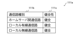
- FIG. 3 is a schematic diagram illustrating an example of communication path soundness information according to the first embodiment.
- FIG. 3 illustrates a communication path health table 111a as an example of communication path health information in the first embodiment.
- the communication path health table 111a includes a communication path type column 111b and a health column 111c.
- the communication path type column 111b stores the communication path type for identifying the communication path monitored by the communication path monitoring unit 112.
- the communication path monitoring unit 112 monitors the home server communication path, the local wired communication path, and the local wireless communication path.
- the home server-to-home communication path is a communication path that passes through the network switches 130A and 130B between the home communication device 150 and the local communication server 120 in FIG.
- the local wired communication path is a communication path that passes through the network switches 130A and 130B between the local communication server 120 and the local wireless communication device 160 in FIG.
- a system communication path is formed by the inter-home server communication path and the local wired communication path.
- the local wireless communication path is a communication path between the local wireless communication device 160 and the mobile communication device 170 in FIG. 1 when communicating using a local wireless method.
- the local wireless communication path is a communication path using a local wireless method between the local wireless communication device 160 and the railway vehicle 4.
- the health column 111c stores whether the communication path identified in the communication path type column 111b is healthy or not. For example, when “healthy” is stored in the health column 111c, it indicates that the communication path identified in the communication path type column 111b of the same row is healthy. On the other hand, when “no” is stored in the health column 111c, it indicates that the communication path identified in the communication path type column 111b of the same row is not healthy.
- the communication path health table 111a can indicate the health of the communication paths between home servers, the local wired communication paths, and the local wireless communication paths.
- the communication path monitoring unit 112 monitors the communication path to be monitored and determines whether the communication path is healthy or not.
- the communication path monitoring unit 112 stores the monitoring result in communication path health information.
- the communication path monitoring unit 112 periodically communicates with a target device via the communication network connection unit 115 in order to identify the soundness of the communication path.
- the health of the home server communication path and the local wired communication path can be identified by acquiring topology information held by the network switches 130A and 130B.
- Topology information is information that indicates how devices are adjacent to each other on the network. By combining topology information with link information that indicates that communication is possible between devices, the communication path monitoring unit 112 can determine the health of the communication path.
- the topology information and link information can be acquired, for example, by using Resilient Protection Ring (RPR), which is a ring control protocol standardized by IEEE (Institute of Electrical and Electronics Engineers) 802.17.
- RPR Resilient Protection Ring
- the network switch 130B in the station 2 may acquire topology information and link information by, for example, IEEE
- LLDP Link Layer Discovery Protocol
- the monitoring control device 110 to acquire the topology information and link information from the network switches 130A and 130B, it is possible to use the Simple Network Management Protocol (SNMP) defined in the Request for Comments (RFC).
- SNMP Simple Network Management Protocol
- the communication path monitoring unit 112 may obtain a determination result as to whether or not the communication with the mobile communication device 170 is sound from the local wireless communication device 160. Specifically, the local wireless communication device 160 observes the reception strength of a signal from the mobile communication device 170, and if the reception strength is equal to or greater than a preset reception strength, determines that the communication with the mobile communication device 170 is sound. As a method for the monitor control device 110 to obtain from the local wireless communication device 160 the determination result as to whether or not communication with the mobile communication device 170 is normal, it is possible to use SNMP.
- the train platform approach determination unit 113 determines whether the train 4 has approached within a set distance of the platform 3, which is the destination. If the train 4 has approached within the set distance of the platform 3, the train platform approach determination unit 113 notifies the communication method switching determination unit 114 that the train 4 has approached.
- the railway vehicle platform approach determination unit 113 may determine that the railway vehicle 4 is approaching the platform 3 using known technology such as a track circuit or CBTC (Communications-Based Train Control).
- the set distance is a distance at which local wireless communication is possible between the mobile communication device 170 and the local wireless communication device 160, and may be set by a dispatcher, or may be a value set from a measured value, for example.
- the determination that the railcar 4 has approached the platform 3 is synonymous with the determination that the railcar 4 has entered the communication range of the local wireless communication device 160.
- the communication method switching determination unit 114 When the communication method switching determination unit 114 receives a notification from the train platform approach determination unit 113, it determines whether the communication method can be switched from the public wireless method to the local wireless method. If the communication method switching determination unit 114 determines that switching is possible, it instructs the mobile communication device 170 of the train 4 and the on-platform communication device 150 of the platform 3 to switch to the local wireless method.
- the communication network connection unit 115 is connected to the network switch 130A and communicates with external devices via the network switch 130A.
- the public communication unit 116 connects to the public communication network 6 and performs communication. For example, the public communication unit 116 transmits the switching instruction from the communication system switching determination unit 114 to the mobile communication device 170 of the railway car 4 via the public communication network 6 .
- the monitoring control device 110 monitors whether the system communication path is healthy and whether the local wireless communication path between the local wireless communication device 160 and the railway vehicle 4 is healthy, and when the railway vehicle 4 enters the communication range of the local wireless communication device 160, if both the system communication path and the local wireless communication path are healthy, the monitoring control device 110 causes the local wireless communication device 160 to transmit video data. On the other hand, if at least one of the system communication path and the local wireless communication path is not healthy, the monitoring control device 110 causes the in-home communication device 150 to transmit the video data.
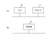
- All or part of the communication path monitoring unit 112, railway vehicle platform approach determination unit 113, and communication method switching determination unit 114 described above can be configured, for example, as shown in FIG. 4(A), with a memory 10 and a processor 11 such as a CPU (Central Processing Unit) that executes a program stored in the memory 10.
- a processor 11 such as a CPU (Central Processing Unit) that executes a program stored in the memory 10.
- a program may be provided over a network, or may be provided by being recorded on a recording medium. That is, such a program may be provided, for example, as a program product.
- some or all of the communication path monitoring unit 112, the railway vehicle platform approach determination unit 113, and the communication method switching determination unit 114 can be configured by a processing circuit 12 such as a single circuit, a composite circuit, a programmed processor, a parallel programmed processor, an ASIC (Application Specific Integrated Circuit), or an FPGA (Field Programmable Gate Array), as shown in FIG. 4(B).
- a processing circuit 12 such as a single circuit, a composite circuit, a programmed processor, a parallel programmed processor, an ASIC (Application Specific Integrated Circuit), or an FPGA (Field Programmable Gate Array), as shown in FIG. 4(B).
- the communication path monitoring unit 112, the railway vehicle platform approach determination unit 113, and the communication method switching determination unit 114 can be configured as a processing circuit network.
- the communication path health information storage unit 111 can be configured by a storage device such as a hard disk drive (HDD), a solid state drive (SSD), a non-volatile memory, or a volatile memory.
- the communication network connection unit 115 can be configured by a communication I/F (InterFace).
- FIG. 5 is a block diagram illustrating a schematic configuration of the network switch 130 according to the first embodiment.
- the network switch 130 includes a communication unit 131 , a communication control unit 132 , a device connection unit 133 , and a transfer processing unit 134 .
- the communication unit 131 is a wired communication I/F that performs wired communication with another adjacent network switch 130 .
- the communication unit 131 includes two communication connection units 131A and 131B that function as wired communication I/Fs in order to configure a ring structure with another network switch 130.
- the communication control unit 132 controls the communication unit 131 to control wired communication via a wired communication path. For example, when the communication unit 131 configures a ring structure, the communication control unit 132 performs control based on the RPR protocol. Specifically, when a single failure occurs in the wired communication network, the communication control unit 132 performs wired communication via a detour in 50 msec or less.
- the communication control unit 132 also detects the topology within the ring using a topology discovery function defined by the RPR protocol. The communication control unit 132 can determine which network switch is connected how many hops away in a clockwise direction on the wired communication network, and how many hops away in a counterclockwise direction on the wired communication network, based on its own device. If a failure occurs in the wired communication network, the communication control unit 132 can recognize the location of the failure in the wired communication network.
- the device connection unit 133 is a communication I/F that can be connected to devices such as the home communication device 150.
- the device connection unit 133 is connected to the monitoring control device 110 and the local communication server 120.
- the device connection unit 133 is connected to the home communication device 150 and the local wireless communication device 160.
- the device connection unit 133 can connect to these devices via a LAN (Local Area Network), for example.
- the device connection unit 133 transfers data sent and received via wired communication between the connected devices.
- the transfer processing unit 134 performs a transfer process for frames that include data. For example, the transfer processing unit 134 transfers frames acquired from a device connected to the device connection unit 133 to the communication control unit 132. The transfer processing unit 134 also transfers frames from the communication control unit 132 to a device connected to the device connection unit 133. The transfer processing unit 134 passes data between the communication control unit 132 and the device connection unit 133.
- the communication control unit 132, the device connection unit 133, and the transfer processing unit 134 described above, in whole or in part, can be configured, for example, as shown in FIG. 4(A), by a memory 10 and a processor 11 that executes a program stored in the memory 10.
- a program may be provided over a network, or may be provided by being recorded on a recording medium. That is, such a program may be provided, for example, as a program product.
- the communication control unit 132, the device connection unit 133, and the transfer processing unit 134 may be partially or entirely configured by the processing circuit 12, as shown in FIG. 4B, for example.
- the communication control unit 132, the device connection unit 133, and the transfer processing unit 134 can be configured as a processing circuit network.
- the communication unit 131 and the device connection unit 133 can be configured using a communication I/F.
- FIG. 6 is a block diagram showing a schematic configuration of the home communication device 150 according to the first embodiment.
- the home communication device 150 includes a public wireless communication unit 151 , a communication network connection unit 152 , a connection control unit 153 , and a device connection unit 154 .
- the public wireless communication unit 151 is used to transmit video data when using a public wireless system. Specifically, the public wireless communication unit 151 connects to the public communication network 6 via the public ground communication station 5 shown in FIG. 1, and transmits the video data.
- the communication network connection unit 152 is connected to the network switch 130B outside the home communication device 150, and communicates with the network switch 130B.
- the communication network connection unit 152 is used for communication with the monitoring control device 110, and for transmitting video data when using the local wireless method.
- the device connection unit 154 is connected to the camera 140 outside the home communication device 150 and communicates with the camera 140 .
- the device connection unit 154 receives video data from the camera 140 and provides the video data to the connection control unit 153 .
- connection control unit 153 is connected to the communication network connection unit 152, the public wireless communication unit 151, and the device connection unit 154, and controls them. For example, the connection control unit 153 receives the result of the communication method switching determination sent from the monitoring and control device 110 via the public wireless communication unit 151, and controls whether to use the public wireless communication unit 151 as is for transmitting video data, or to switch to the communication network connection unit 152.
- connection control unit 153 can be configured, for example, as shown in FIG. 4(A), with a memory 10 and a processor 11 that executes a program stored in the memory 10.
- a program may be provided over a network, or may be provided by being recorded on a recording medium. That is, such a program may be provided, for example, as a program product.
- connection control section 153 can be configured by the processing circuit 12, for example, as shown in FIG. 4(B).
- the connection control unit 153 can be configured with a processing circuit network.
- the communication network connection unit 152, the public wireless communication unit 151, and the device connection unit 154 can be configured using a communication I/F.
- FIG. 7 is a block diagram showing a schematic configuration of the local wireless communication device 160 according to the first embodiment.
- the local wireless communication device 160 includes a communication network connection unit 161 and a local wireless communication unit 162 .
- the communication network connection unit 161 is connected to the network switch 130B outside the local wireless communication device 160, and is a wired communication I/F that communicates with the network switch 130B.
- the communication network connection unit 161 receives video data from the network switch 130B. The received video data is provided to the local wireless communication unit 162.
- the local wireless communication unit 162 is a wireless communication I/F that performs communication using a local wireless system. For example, when using the local wireless communication system, the local wireless communication unit 162 transmits image data from the camera 140 provided by the communication network connection unit 161 to the mobile communication device 170 .
- FIG. 8 is a block diagram showing a schematic configuration of a mobile communication device 170 according to the first embodiment.
- the mobile communication device 170 includes a public wireless communication unit 171 , a local wireless communication function unit 172 , a communication control unit 173 , and a device connection unit 174 .
- the public wireless communication unit 171 is connected to a public communication network 6 via a public ground communication station 5 .
- the public wireless communication unit 171 is connected to the communication control unit 173 and receives video data when the public wireless system is used.
- the public wireless communication unit 171 also receives a switching instruction transmitted from the monitor and control device 110.
- the local wireless communication function unit 172 performs communication using a local wireless system.
- the local wireless communication function unit 172 is connected to the communication control unit 173 and receives video data when the local wireless system is used.
- the communication control unit 173 is connected to the public wireless communication unit 171, the local wireless communication function unit 172, and the device connection unit 174, and controls them. For example, the communication control unit 173 receives a communication method switching instruction sent from the monitoring control device 110, and controls whether to continue using the public wireless communication unit 171 to transmit video data from the camera 140, or to switch to the local wireless communication function unit 172.
- the device connection unit 174 communicates with other devices outside the mobile communication device 170 .
- the device connection section 174 is connected to a camera monitor 180 outside the mobile communication device 170 and is used for the camera monitor 180 to communicate with an external device.
- a part or all of the communication control unit 173 described above can be configured, for example, as shown in FIG. 4(A), with a memory 10 and a processor 11 that executes a program stored in the memory 10.
- a program may be provided over a network, or may be provided by being recorded on a recording medium. That is, such a program may be provided, for example, as a program product.
- a part or the whole of the communication control unit 173 can be configured by the processing circuit 12, for example, as shown in FIG. 4(B).
- the communication control unit 173 can be configured with a processing circuit network.
- the device connection unit 174 can be configured by a communication I/F.
- the public wireless communication unit 171 and the local wireless communication function unit 172 can be configured by a wireless communication I/F.
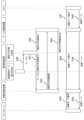
- FIG. 9 is a sequence diagram showing the operation of the mobile communication system 100 according to the first embodiment.
- FIG. 9 shows an operation in which the monitoring control device 110 in the first embodiment switches the communication system from the public wireless system to the local wireless system before the video data from the camera 140 is displayed on the camera monitor 180.
- the railway vehicle platform approach determination unit 113 of the monitoring control device 110 gives an approach notification to the communication method switching determination unit 114 indicating that the railway vehicle 4 is approaching the platform 3 (S10).
- the communication method switching determination unit 114 when the communication method switching determination unit 114 receives the approach notification, it refers to the communication path health information stored in the communication path health information storage unit 111 and determines whether or not the communication method between the mobile communication device 170 and the in-home communication device 150 can be switched to the local wireless method.
- the contents of the determination process here will be described later. Here, the explanation will be given assuming that the determination result for switching the communication method is yes.
- the communication method switching determination unit 114 of the monitoring and control device 110 causes the public communication unit 116 to transmit a communication method switching instruction to the mobile communication device 170 via the public communication network 6 (S11).
- the switching instruction here is an instruction to switch to the local wireless communication method.
- the communication method switching determination unit 114 of the monitoring control device 110 also causes the communication network connection unit 115 to transmit a communication method switching instruction to the home communication device 150 (S12).
- This communication method switching instruction can be transmitted using, for example, a local wired communication path.
- the communication control unit 173 of the mobile communication device 170 causes the local wireless communication function unit 172 to transmit a communication method switching confirmation to the in-home communication device 150 of home 3 using the local wireless method (S13).
- This switching confirmation is transmitted to the in-home communication device 150 via the local wireless communication device 160, network switch 130B, network switch 130A, local communication server 120, network switch 130A, and network switch 130B.
- connection control unit 153 of the home communication device 150 causes the device connection unit 154 to transmit a communication method switching confirmation response (S14).
- This switching confirmation response is transmitted to the mobile communication device 170 via the network switch 130B, the network switch 130A, the local communication server 120, the network switch 130A, the network switch 130B, and the local wireless communication device 160.
- the camera monitor 180 of the railway vehicle 4 causes the mobile communication device 170 to transmit a video data request to the camera 140 (S15).
- the communication method used for data transmission is the local wireless communication method if the mobile communication device 170, which transmitted the communication method switching confirmation in step S13, receives a communication method switching confirmation response within a certain period of time in step S14. On the other hand, if such a switching confirmation response is not received within the certain period of time, the public wireless method is used.
- the mobile communication device 170 receives the video data request at the device connection unit 174 and provides the video data request to the communication control unit 173.
- the communication control unit 173 causes the local wireless communication function unit 172 to transmit the video data request to the camera 140 (S16).
- the local wireless communication unit 162 of the local wireless communication device 160 receives the video data request, and the received video data request is provided from the communication network connection unit 161 to the network switch 130B, and is transmitted to the camera 140 via the network switch 130A, the local communication server 120, the network switch 130A, the network switch 130B, and the home communication device 150 (S17).
- the camera 140 transmits the video data to the camera monitor 180 (S18).
- This video data is transmitted to the local wireless communication device 160 via the home communication device 150, network switch 130B, network switch 130A, local communication server 120, network switch 130A, and network switch 130B.
- the video data is transmitted from the local wireless communication unit 162 (S19).
- the local wireless communication function unit 172 receives the video data and provides the video data to the communication control unit 173.
- the communication control unit 173 causes the device connection unit 174 to transmit the video data to the camera monitor 180 (S20).
- the mobile communication system 100 can switch the communication method from the public wireless method to the local wireless method and reliably transmit video data from the camera 140 to the camera monitor 180.
- the communication method switching determination unit 114 determines that the communication method cannot be switched, the communication method is not switched and the public wireless method is used as is.
- the camera 140 and the camera monitor 180 transmit and receive the video data request and the video data using the public wireless method.
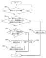
- FIG. 10 is a flowchart showing the process in which the communication method switching determination unit 114 of the monitoring and control device 110 determines whether to switch the communication method from the public wireless method to the local wireless method.
- the communication method switching determination unit 114 of the monitoring control device 110 determines whether or not an approach notification indicating that the railway vehicle 4 is approaching the platform 3 has been received from the railway vehicle platform approach determination unit 113 (S30). If an approach notification has been received (Yes in S30), the process proceeds to step S31.
- step S31 the communication method switching determination unit 114 checks the health of the local wireless communication path, the local wired communication path, and the communication path between home servers by referring to the communication path health information stored in the communication path health information storage unit 111, and determines whether all of these communication paths are healthy. If at least one of these communication paths is not healthy (No in S31), the process proceeds to step S32, and if all of these communication paths are healthy (Yes in S31), the process proceeds to step S33.
- step S32 the communication method switching determination unit 114 determines that at least one of the communication paths is not healthy and therefore switching to the local wireless method cannot be performed.
- step S33 the communication method switching determination unit 114 determines that all communication paths are healthy and therefore that switching to the local wireless method can be performed.
- the communication method switching determination unit 114 outputs a communication method switching instruction to the mobile communication device 170 and the home communication device 150 (S34).
- Embodiment 2 In the first embodiment, image data from a camera 140 on one platform 3 where a railcar 4 arrives is received, but in the second embodiment, an example will be described in which there are a plurality of platforms.
- FIG. 11 is a block diagram showing a schematic configuration of a mobile communication system 200 according to the second embodiment.
- the mobile communication system 200 is described as a system used in a control room 1, a station 2, and a railway car 4.
- a plurality of platforms 3A, 3B are provided in the station 2.
- each of the platforms 3A, 3B will be referred to as a platform 3.
- two platforms 3A, 3B are shown in Fig. 11, three or more platforms 3 may be provided.
- a camera 140A, an in-home communication device 150A, and a local wireless communication device 160A are arranged in home 3A
- a camera 140B, an in-home communication device 150B, and a local wireless communication device 160B are arranged in home 3B.
- the configurations of the cameras 140A, 140B, the home communication devices 150A, 150B, and the local wireless communication devices 160A, 160B are the same as the camera 140, the home communication device 150, and the local wireless communication device 160 in the first embodiment.
- the cameras 140A and 140B, the in-home communication devices 150A and 150B, and the local wireless communication devices 160A and 160B will be referred to as the cameras 140, the in-home communication devices 150, and the local wireless communication devices 160, respectively.
- the local communication server 120, network switch 130 and mobile communication device 170 of the mobile communication system 200 of embodiment 2 are similar to the local communication server 120, network switch 130 and mobile communication device 170 of the mobile communication system 100 of embodiment 1.
- home communication devices 150A and 150B and local wireless communication devices 160A and 160B are connected to the network switch 130B.
- the crew aboard the railway vehicle 4 is able to select the image data captured by the multiple cameras 140A, 140B that is to be displayed on the camera monitor 280.
- the crew aboard the railway vehicle 4 can select either platform 3A or 3B on the camera monitor 280, and the image shown by the image data from the camera 140 located on the selected platform 3 is displayed on the camera monitor 280.
- a home ID is assigned to each of the homes 3A and 3B as home identification information, which is identification information for identifying the home 3, and the home ID makes it possible to identify the camera 140, the in-home communication device 150, and the local wireless communication device 160 arranged on the home 3.
- the monitoring and control device 210 in embodiment 2 includes a communication path health information storage unit 211, a communication path monitoring unit 212, a railway vehicle platform approach determination unit 213, a communication method switching determination unit 214, a communication network connection unit 115, and a public communication unit 116.
- the communication network connection unit 115 and the public communication unit 116 of the monitor and control device 210 in the second embodiment are similar to the communication network connection unit 115 and the public communication unit 116 of the monitor and control device 110 in the first embodiment.
- the communication path soundness information storage unit 211 stores communication path soundness information indicating the soundness of the communication path monitored by the communication path monitoring unit 212 .
- the communication path monitoring unit 212 monitors the communication paths between each of the intra-home communication devices 150A, 150B, which are located in the multiple homes 3A, 3B, and each of the local wireless communication devices 160A, 160B. Therefore, the communication path health information in embodiment 2 indicates whether the communication paths between each of the intra-home communication devices 150A, 150B, which are located in the multiple homes 3A, 3B, and each of the local wireless communication devices 160A, 160B are healthy.
- FIG. 12 is a schematic diagram illustrating an example of communication path soundness information according to the second embodiment.
- FIG. 12 shows a communication path health table 211a as an example of communication path health information.
- the communication path health table 211a includes a communication path type column 211b, a home ID column 211c, and a health column 211d.
- the communication path type column 211b stores the communication path type for identifying the communication path monitored by the communication path monitoring unit 212.
- the communication path monitoring unit 212 also monitors the inter-home server communication path, the local wired communication path, and the local wireless communication path.
- a system communication path is formed by combining an inter-home server communication path and a local wired communication path.
- the home server-to-home communication path is a communication path that passes through network switches 130A and 130B between the home communication device 150A and the local communication server 120, or a communication path that passes through network switches 130A and 130B between the home communication device 150B and the local communication server 120.
- the local wired communication path is a communication path that passes through network switches 130A and 130B between the local communication server 120 and the local wireless communication device 160A, or a communication path that passes through network switches 130A and 130B between the local communication server 120 and the local wireless communication device 160B.
- the local wireless communication path refers to a communication path when communication is performed using a local wireless method between local wireless communication device 160A and mobile communication device 170, or a communication path when communication is performed using a local wireless method between local wireless communication device 160B and mobile communication device 170.
- the home ID column 211c stores the home ID of the home 3 in which the intra-home communication devices 150A, 150B or the local wireless communication devices 160A, 160B are located.
- AAA indicates home 3A
- BBB indicates home 3B.
- the health column 211d stores whether the communication path identified in the communication path type column 211b and the home ID column 211c is healthy or not.
- the communication path health table 211a can show the health of the home server communication path, the local wired communication path, and the local wireless communication path for each home 3 indicated by the home ID.
- the communication path monitoring unit 212 monitors the communication path to be monitored in each of homes 3A and 3B, and determines whether the communication path is healthy or not.
- the communication path monitoring unit 212 stores the monitoring result in communication path health information.
- the specific processing in the communication path monitoring unit 212 is the same as in embodiment 1.
- the train platform approach determination unit 213 determines whether the train 4 has approached within a set distance of the destination platform 3 for each platform 3. If the train 4 has approached within the set distance of the platform 3, the train platform approach determination unit 213 notifies the communication method switching determination unit 214 of the platform ID of the platform 3 that the train 4 has approached.
- the communication method switching determination unit 214 When the communication method switching determination unit 214 receives a notification from the train platform approach determination unit 213, it determines whether the communication method can be switched from the public wireless method to the local wireless method. If the communication method switching determination unit 214 determines that switching is possible, it instructs the mobile communication device 170 of the train 4 and the on-platform communication device 150 of the platform 3, where the camera 140 that acquires the video data is located, to switch to the local wireless method.
- FIG. 13 is a sequence diagram showing the operation of the mobile communication system 200 according to the second embodiment.
- the crew of the railway car 4 requests the display of an image captured by the camera 140B installed on the platform 3B.
- FIG. 13 shows an operation of the monitor and control device 210 in the second embodiment for switching the communication system from the public wireless system to the local wireless system.
- the second embodiment unlike the first embodiment, in order to allow the crew to arbitrarily switch the video they wish to acquire, the soundness between the local wireless communication device 160 installed on the platform 3 where the railway vehicle 4 arrives and the mobile communication device 170, as well as the soundness of all communication paths between the local wireless communication device 160 installed on the platform 3 where the railway vehicle 4 arrives and the on-platform communication devices 150A, 150B within the station 2, is confirmed, and a decision is made to switch to the local wireless system.
- the railway vehicle platform approach determination unit 213 of the monitoring control device 210 notifies the communication method switching determination unit 214 of "AAA", which is the platform ID of the platform 3A that the railway vehicle 4 has approached (S40).
- the communication method switching determination unit 214 when the communication method switching determination unit 214 receives notification of the home ID, it refers to the communication path health information stored in the communication path health information storage unit 211 and determines whether or not it is possible to switch the communication method between the mobile communication device 170 and the in-home communication devices 150A, 150B to the local wireless method.
- the contents of the determination process here will be described later, but in embodiment 2, unlike embodiment 1, it is determined whether or not it is possible to switch the communication method to the local wireless method between the mobile communication device 170 and all in-home communication devices 150A, 150B located at station 2.
- the explanation will be given assuming that the determination result for switching the communication method is possible.
- the communication method switching determination unit 214 of the monitoring control device 210 causes the public communication unit 116 to transmit a communication method switching instruction to the mobile communication device 170 via the public communication network 6 (S41).
- the switching instruction here is an instruction to switch to the local wireless communication method provided by the local wireless communication device 160A of the platform 3A to which the railroad vehicle 4 is approaching, and includes the platform ID of the platform 3A.
- the communication method switching determination unit 214 of the monitoring control device 210 also causes the communication network connection unit 115 to transmit a communication method switching instruction to all of the in-home communication devices 150 (here, the in-home communication devices 150A and 150B) (S42).
- This communication method switching instruction can be transmitted using, for example, a local wired communication path.
- the communication control unit 173 of the mobile communication device 170 causes the local wireless communication function unit 172 to transmit a communication method switching confirmation to all of the in-home communication devices 150 using the local wireless method (S43).
- This switching confirmation is transmitted to the in-home communication devices 150A and 150B via the local wireless communication device 160A, the network switch 130B, the network switch 130A, the local communication server 120, the network switch 130A, and the network switch 130B.
- connection control units 153 of all the in-home communication devices 150 cause the device connection units 154 to transmit a communication method switching confirmation response (S44).
- This switching confirmation response is transmitted from the in-home communication devices 150A and 150B to the mobile communication device 170 via the network switch 130B, the network switch 130A, the local communication server 120, the network switch 130A, the network switch 130B, and the local wireless communication device 160A.
- the camera monitor 280 of the railway car 4 causes the mobile communication device 170 to transmit a video data request to the camera 140B (S45).
- the communication method used for data transmission is the local wireless communication method if the mobile communication device 170, which transmitted the communication method switching confirmation in step S43, receives a communication method switching confirmation response from the in-home communication device 150B within a certain period of time in step S44. On the other hand, if such a switching confirmation response is not received within the certain period of time, the public wireless method is used.
- the mobile communication device 170 receives the video data request for home 3B at the device connection unit 174, and provides the video data request to the communication control unit 173.
- the communication control unit 173 causes the local wireless communication function unit 172 to transmit the video data request to the camera 140B (S46).
- the local wireless communication unit 162 of the local wireless communication device 160A receives the video data request, and the received video data request is provided from the communication network connection unit 161 to the network switch 130B, and is then transmitted to the camera 140B via the network switch 130A, the local communication server 120, the network switch 130A, the network switch 130B, and the home communication device 150B (S47).
- the camera 140B transmits the video data to the camera monitor 280 (S48).
- This video data is transmitted to the local wireless communication device 160A via the home communication device 150B, the network switch 130B, the network switch 130A, the local communication server 120, the network switch 130A, and the network switch 130B.
- the video data is transmitted from the local wireless communication unit 162 (S49).
- the local wireless communication function unit 172 receives the video data and provides the video data to the communication control unit 173.
- the communication control unit 173 causes the device connection unit 174 to transmit the video data to the camera monitor 280 (S50).
- the mobile communication system 200 can switch the communication method from the public wireless method to the local wireless method and reliably transmit video data from the camera 140B to the camera monitor 280.
- the communication method switching determination unit 214 which has received the home ID notification in step S40, determines that the communication method cannot be switched, the public wireless method is used as is without switching the communication method.
- the camera 140B and the camera monitor 280 transmit and receive the video data request and the video data using the public wireless method.
- FIG. 14 is a flowchart showing the process in which the communication method switching determination unit 214 of the monitoring and control device 210 determines whether to switch the communication method from the public wireless method to the local wireless method.
- the communication method switching determination unit 214 of the monitoring control device 210 determines whether or not the platform ID of the platform 3 that the railcar 4 is approaching has been received from the railcar platform approach determination unit 213 (S60). If a notification of the platform ID has been received (Yes in S60), the process proceeds to step S61.
- step S61 the communication method switching determination unit 214 checks the health of both the local wired communication path and the local wireless communication path associated with the home ID received in step S60 by referring to the communication path health information stored in the communication path health information storage unit 211, and determines whether both communication paths are healthy. If at least one of these communication paths is not healthy (No in S61), the process proceeds to step S62, and if both communication paths are healthy (Yes in S61), the process proceeds to step S63.
- step S62 the communication method switching determination unit 214 determines that at least one of the local wired communication path and the local wireless communication path is not healthy on the platform 3 to which the railcar 4 is approaching, and therefore switching to the local wireless method cannot be performed.
- step S63 the communication method switching determination unit 214 determines whether all inter-home server communication paths, which are communication paths between all intra-home communication devices 150 arranged in all homes 3 and the local communication server 120, are healthy. If at least one inter-home server communication path is not healthy (No in S63), the process proceeds to step S64, and if all inter-home server communication paths are healthy (Yes in S63), the process proceeds to step S65.
- step S64 the communication method switching determination unit 214 determines that it is not possible to switch to the local wireless method because it is not possible to acquire video data from the cameras 140 located on any of the platforms 3.
- step S65 the communication method switching determination unit 214 determines that all communication paths are healthy and therefore that switching to the local wireless method can be performed.
- the communication method switching determination unit 214 outputs the platform ID acquired in step S60 and an instruction to switch the communication method to the mobile communication device 170, and outputs an instruction to switch the communication method to the in-platform communication device 150 on platform 3, where the camera 140 capturing the image that the train driver of the railway car 4 wishes to display is located (S66).
- a plurality of intra-home communication devices 150 and a plurality of local wireless communication devices 160 are provided by arranging the intra-home communication devices 150 and the local wireless communication devices 160 in association with each of a plurality of homes 3. Then, a plurality of system communication paths are formed between the intra-home communication devices 150 and the local wireless communication devices 160, thereby forming a plurality of system communication paths between the plurality of intra-home communication devices 150 and the plurality of local wireless communication devices 160.
- the monitoring control device 210 in the second embodiment transmits video data to the local wireless communication device 160 associated with the arrival platform.
- the monitoring control device 210 transmits video data to the in-home communication device 150 associated with the arrival platform.
- each of the multiple in-home communication devices 150 is connected to each of the multiple cameras 140.
- Each of the multiple cameras 140 acquires video data capturing images of each of the multiple platforms 3 as target data.
- the communication path between the platform communication device 150 on the platform 3 and the mobile communication device 170 on the railway car 4 determines whether or not it is possible to switch to a local wireless system before requesting video data, so that communication can be performed reliably even if the communication system is switched to the local wireless system.
- the health of the communication path for each railway vehicle 4 is stored in the communication path health information using a railway vehicle ID, which is railway vehicle identification information for identifying the railway vehicle 4, so that the switching of communication methods can be managed for each of the multiple railway vehicles 4.
- Embodiment 3 The second embodiment is a case where video data is received from a camera 140 selected from a plurality of cameras 140 arranged on a plurality of platforms 3 at a single station 2, whereas the third embodiment will be described for a case where there are a plurality of stations.
- FIG. 15 is a block diagram showing a schematic configuration of a mobile communication system 300 according to the third embodiment.
- the mobile communication system 300 is described as a system used in a command room 1, stations 2A, 2B, and a railway vehicle 4.
- a plurality of stations 2A, 2B are provided with a plurality of platforms 3A, 3B, respectively.
- each of the stations 2A, 2B is referred to as a station 2.
- each of the platforms 3A, 3B is referred to as a platform 3.
- two stations 2A, 2B and two platforms 3A, 3B are shown, but three or more stations 2 or three or more platforms 3 may be provided.
- the mobile communication system 300 includes a monitoring and control device 310, a local communication server 120, network switches 130A, 130B, and 130C, cameras 140A and 140B, home communication devices 150A and 150B, local wireless communication devices 160A and 160B, a mobile communication device 170, and a camera monitor 380.
- a network switch 130A is provided in the command room 1.
- a network switch 130B and a platform 3A are provided in the station 2A, and a camera 140A, an in-platform communication device 150A, and a local wireless communication device 160A are provided in the platform 3A.
- a network switch 130C and a platform 3B are provided in the station 2B, and a camera 140B, an in-platform communication device 150B, and a local wireless communication device 160B are provided in the platform 3B.
- An in-home communication device 150A and a local wireless communication device 160A are connected to the network switch 130B, and an in-home communication device 150B and a local wireless communication device 160B are connected to the network switch 130C.
- the configurations of the network switches 130A, 130B, 130C, the cameras 140A, 140B, the home communication devices 150A, 150B, and the local wireless communication devices 160A, 160B are the same as the network switch 130, the camera 140, the home communication device 150, and the local wireless communication device 160 in embodiment 1.
- the network switches 130A, 130B, and 130C When there is no need to distinguish between the network switches 130A, 130B, and 130C, the cameras 140A and 140B, the home communication devices 150A and 150B, and the local wireless communication devices 160A and 160B, the network switches 130A, 130B, and 130C, the cameras 140A and 140B, the home communication devices 150A and 150B, and the local wireless communication devices 160A and 160B will be referred to as the network switch 130, the camera 140, the home communication device 150, and the local wireless communication device 160, respectively.
- the local communication server 120 and the mobile communication device 170 of the mobile communication system 300 according to the third embodiment are similar to the local communication server 120 and the mobile communication device 170 of the mobile communication system 100 according to the first embodiment.
- the crew aboard the railway vehicle 4 is able to select the image data captured by the multiple cameras 140A, 140B that is to be displayed on the camera monitor 380.
- the crew aboard the railway vehicle 4 can select on the camera monitor 380 either the combination of station 2A and platform 3A, or the combination of station 2B and platform 3B, and the image shown by the image data from the camera 140 located on platform 3 included in the selected combination is displayed on the camera monitor 380.
- a station ID is assigned to each of stations 2A and 2B as station identification information, which is identification information for identifying station 2
- a platform ID is assigned to each of platforms 3A and 3B as platform identification information, which is identification information for identifying platform 3.
- the station ID and platform ID make it possible to identify the cameras 140, intra-platform communication devices 150, and local wireless communication devices 160 located at station 2 and platform 3.
- the monitoring and control device 310 in embodiment 3 includes a communication path health information storage unit 311, a communication path monitoring unit 312, a railway vehicle platform approach determination unit 313, a communication method switching determination unit 314, a communication network connection unit 115, and a public communication unit 116.
- the communication network connection unit 115 and the public communication unit 116 of the monitor and control device 310 in the third embodiment are similar to the communication network connection unit 115 and the public communication unit 116 of the monitor and control device 110 in the first embodiment.
- the communication path soundness information storage unit 311 stores communication path soundness information indicating the soundness of the communication path monitored by the communication path monitoring unit 312 .
- the communication path monitoring unit 312 monitors the communication paths between each of the in-home communication devices 150A, 150B and each of the local wireless communication devices 160A, 160B, which are located on multiple platforms 3A, 3B at multiple stations 2A, 2B. Therefore, the communication path health information in embodiment 3 indicates whether the communication paths between each of the in-home communication devices 150A, 150B and each of the local wireless communication devices 160A, 160B, which are located on multiple platforms 3A, 3B at multiple stations 2A, 2B, are healthy.
- FIG. 16 is a schematic diagram illustrating an example of communication path soundness information in the third embodiment.
- FIG. 16 shows a communication path health table 311a as an example of communication path health information.
- the communication path health table 311a has a communication path type column 311b, a station ID column 311c, a platform ID column 311d, and a health column 311e.
- the communication path type column 311b stores the communication path type for identifying the communication path monitored by the communication path monitoring unit 312.
- the communication path monitoring unit 312 also monitors the inter-home server communication path, the local wired communication path, and the local wireless communication path.
- a system communication path is formed by combining an inter-home server communication path and a local wired communication path.
- the home server-to-home communication path is a communication path that passes through network switches 130A and 130B between the home communication device 150A and the local communication server 120, or a communication path that passes through network switches 130A and 130C between the home communication device 150B and the local communication server 120.
- the local wired communication path is a communication path that passes through network switches 130A and 130B between the local communication server 120 and the local wireless communication device 160A, or a communication path that passes through network switches 130A and 130C between the local communication server 120 and the local wireless communication device 160B.
- the local wireless communication path refers to a communication path when communication is performed using a local wireless method between local wireless communication device 160A and mobile communication device 170, or a communication path when communication is performed using a local wireless method between local wireless communication device 160B and mobile communication device 170.
- the station ID column 311c stores the station ID of station 2 where platform 3 is located.
- "XXX” indicates station 2A
- "YYY” indicates station 2B.
- the home ID column 311d stores the home ID of the home 3 in which the intra-home communication devices 150A, 150B or the local wireless communication devices 160A, 160B are located.
- AAA indicates home 3A
- BBB indicates home 3B.
- the health column 211e stores whether the communication path identified in the communication path type column 311b, the station ID column 311c, and the platform ID column 311d is healthy or not.
- the communication path health table 311a can show the health of the home server communication path, the local wired communication path, and the local wireless communication path for each combination of a station 2 indicated by a station ID and a platform 3 indicated by a platform ID.
- the communication path monitoring unit 312 monitors the communication path to be monitored for each combination of station 2 and platform 3, and determines whether the communication path is healthy or not.
- the communication path monitoring unit 312 stores the monitoring result in communication path health information.
- the specific processing in the communication path monitoring unit 312 is the same as in the first embodiment.
- the train platform approach determination unit 313 determines whether the train 4 has approached within a set distance of the platform 3 of the station 2, which is the destination, for each combination of station 2 and platform 3. If the train 4 has approached within the set distance of the platform 3 of the station 2, the train platform approach determination unit 313 notifies the communication method switching determination unit 314 of the station ID and platform ID of the platform 3 of the station 2 that the train 4 has approached.
- the communication method switching determination unit 314 When the communication method switching determination unit 314 receives a notification from the train platform approach determination unit 313, it determines whether the communication method can be switched from the public wireless method to the local wireless method. If the communication method switching determination unit 314 determines that switching is possible, it instructs the mobile communication device 170 of the train 4 and the on-platform communication device 150 on the platform 3 of the station 2, where the camera 140 that acquires the video data is located, to switch to the local wireless method.
- FIG. 17 is a sequence diagram showing the operation of the mobile communication system 300 according to the third embodiment.
- railcar 4 arrives at platform 3A of station 2A, and the crew of railcar 4 requests to see the image captured by camera 140B installed on platform 3B of station 2B.
- FIG. 17 shows an operation of the monitor and control device 310 in the third embodiment for switching the communication system from the public wireless system to the local wireless system.
- embodiment 3 unlike embodiment 1, in order to allow the crew to arbitrarily switch the video they wish to acquire, the soundness between the local wireless communication device 160 installed on the platform 3 where the railway vehicle 4 arrives and the mobile communication device 170, as well as the soundness of all communication paths between the local wireless communication device 160 installed on the platform 3 where the railway vehicle 4 arrives and the platform communication devices 150A, 150B within the station 2 are confirmed, and a decision is made to switch to the local wireless system.
- the railway vehicle platform approach determination unit 313 of the monitoring and control device 310 notifies the communication method switching determination unit 314 of the station ID of station 2A, "XXX", and the platform ID of platform 3A, "AAA” (S70).
- the communication method switching determination unit 314 when the communication method switching determination unit 314 receives notification of the station ID and platform ID, it refers to the communication path health information stored in the communication path health information storage unit 311 to determine whether or not it is possible to switch the communication method between the mobile communication device 170 and the in-platform communication devices 150A, 150B to the local wireless method.
- the contents of the determination process here will be described later, but unlike in embodiment 1, in embodiment 3, it is determined whether or not it is possible to switch the communication method to the local wireless method between the mobile communication device 170 and all in-platform communication devices 150A, 150B located in station 2.
- the explanation will be given assuming that the determination result for switching the communication method is possible.
- the communication method switching determination unit 314 of the monitoring control device 310 causes the public communication unit 116 to transmit a communication method switching instruction to the mobile communication device 170 via the public communication network 6 (S71).
- the switching instruction here is an instruction to switch to the local wireless communication method provided by the local wireless communication device 160A located on platform 3A of station 2A to which the railroad vehicle 4 is approaching, and includes the station ID of station 2A and the platform ID of platform 3A.
- the communication method switching determination unit 314 of the monitoring control device 310 also causes the communication network connection unit 115 to transmit a communication method switching instruction to all of the in-home communication devices 150 (here, the in-home communication devices 150A and 150B) (S72).
- This communication method switching instruction can be transmitted using, for example, a local wired communication path.
- the communication control unit 173 of the mobile communication device 170 causes the local wireless communication function unit 172 to transmit a communication method switching confirmation to all of the in-home communication devices 150 using the local wireless method (S73).
- This switching confirmation is transmitted to the in-home communication device 150A via the local wireless communication device 160A, network switch 130B, network switch 130A, local communication server 120, network switch 130A, and network switch 130B.
- This switching confirmation is also transmitted to the in-home communication device 150B via the local wireless communication device 160A, network switch 130B, network switch 130A, local communication server 120, network switch 130A, and network switch 130C.
- connection control units 153 of all the in-home communication devices 150 cause the device connection units 154 to transmit a communication method switching confirmation response (S74).
- This switching confirmation response is transmitted from the in-home communication device 150A to the mobile communication device 170 via the network switch 130B, the network switch 130A, the local communication server 120, the network switch 130A, the network switch 130B, and the local wireless communication device 160A.
- this switching confirmation response is transmitted from the in-home communication device 150B to the mobile communication device 170 via the network switch 130C, the network switch 130A, the local communication server 120, the network switch 130A, the network switch 130B, and the local wireless communication device 160A.
- the camera monitor 380 of the railway car 4 causes the mobile communication device 170 to transmit a video data request to the camera 140B (S75).
- the communication method used for data transmission is the local wireless communication method if the mobile communication device 170, which transmitted the communication method switching confirmation in step S73, receives a communication method switching confirmation response from the in-home communication device 150B within a certain period of time in step S74. On the other hand, if such a switching confirmation response is not received within the certain period of time, the public wireless method is used.
- the mobile communication device 170 receives a request for video data of platform 3B at station 2B at the device connection unit 174, and provides the video data request to the communication control unit 173.
- the communication control unit 173 causes the local wireless communication function unit 172 to transmit the video data request to camera 140B (S76).
- the local wireless communication unit 162 of the local wireless communication device 160A receives the video data request, and the received video data request is provided from the communication network connection unit 161 to the network switch 130B, and is then transmitted to the camera 140B via the network switch 130A, the local communication server 120, the network switch 130A, the network switch 130C, and the home communication device 150B (S77).
- the camera 140B transmits the video data to the camera monitor 380 (S78).
- This video data is transmitted to the local wireless communication device 160A via the home communication device 150B, the network switch 130C, the network switch 130A, the local communication server 120, the network switch 130A, and the network switch 130B.
- the video data is transmitted from the local wireless communication unit 162 (S79).
- the local wireless communication function unit 172 receives the video data and provides the video data to the communication control unit 173.
- the communication control unit 173 causes the device connection unit 174 to transmit the video data to the camera monitor 380 (S80).
- the mobile communication system 300 can switch the communication method from the public wireless method to the local wireless method and reliably transmit video data from the camera 140B to the camera monitor 380.
- the communication method switching determination unit 314 which has received notification of the station ID and platform ID in step S70, determines that the communication method cannot be switched, the public wireless method is used as is without switching the communication method.
- the camera 140B and the camera monitor 380 send and receive video data requests and video data using the public wireless method.
- FIG. 18 is a flowchart showing the process in which the communication method switching determination unit 314 of the monitoring and control device 310 determines whether to switch the communication method from the public wireless method to the local wireless method.
- the communication method switching determination unit 314 of the monitoring control device 310 determines whether or not it has received the station ID and platform ID of the platform 3 of the station 2 that the railcar 4 has approached from the railcar platform approach determination unit 313 (S90). If it has received notification of the station ID and platform ID (Yes in S90), the process proceeds to step S91.
- step S91 the communication method switching determination unit 314 refers to the communication path health information stored in the communication path health information storage unit 311, checks the health of both the local wired communication path and the local wireless communication path associated with the combination of the station ID and platform ID received in step S90, and determines whether both communication paths are healthy. If at least one of these communication paths is not healthy (No in S91), the process proceeds to step S92, and if both communication paths are healthy (Yes in S91), the process proceeds to step S93.
- step S92 the communication method switching determination unit 314 determines that at least one of the local wired communication path and the local wireless communication path is not healthy at the station 2 and platform 3 to which the railway vehicle 4 is approaching, and therefore it is not possible to switch to the local wireless method.
- step S93 the communication method switching determination unit 314 determines whether all inter-home server communication paths, which are communication paths between all in-home communication devices 150 located in all stations 2 and platforms 3 and the local communication server 120, are healthy. If at least one inter-home server communication path is not healthy (No in S93), the process proceeds to step S94, and if all inter-home server communication paths are healthy (Yes in S93), the process proceeds to step S95.
- step S94 the communication method switching determination unit 314 determines that it is not possible to switch to the local wireless method because it is unable to acquire video data from the cameras 140 located on any of the platforms 3.
- step S95 the communication method switching determination unit 314 determines that all communication paths are healthy and therefore it is possible to switch to the local wireless method.
- the communication method switching determination unit 314 outputs the station ID and platform ID acquired in step S90 and a communication method switching instruction to the mobile communication device 170, and outputs a communication method switching instruction to the on-platform communication device 150 at station 2 and platform 3 where the camera 140 capturing the image that the train crew member of the railway car 4 wishes to display is located (S96).
- a plurality of in-home communication devices 150 and a plurality of local wireless communication devices 160 are provided by arranging the in-home communication devices 150 and the local wireless communication devices 160 in association with each of a plurality of platforms of a plurality of stations.
- a plurality of system communication paths are formed between the in-home communication devices 150 and the local wireless communication devices 160, thereby forming a plurality of system communication paths between the plurality of in-home communication devices 150 and the plurality of local wireless communication devices 160.
- the monitoring control device 310 in the third embodiment transmits video data to the local wireless communication device 160 associated with the arrival platform.
- the monitoring control device 310 transmits video data to the in-home communication device 150 associated with the arrival platform.
- each of the multiple in-home communication devices 150 is connected to each of the multiple cameras 140.
- Each of the multiple cameras 140 acquires video data capturing images of each of the multiple platforms 3 as target data.
- the health of the communication path for each railway vehicle 4 is stored in the communication path health information using a railway vehicle ID, which is railway vehicle identification information for identifying the railway vehicle 4, so that the switching of communication methods can be managed for each of the multiple railway vehicles 4.
Landscapes
- Engineering & Computer Science (AREA)
- Computer Networks & Wireless Communication (AREA)
- Signal Processing (AREA)
- Mobile Radio Communication Systems (AREA)
Abstract
Description
図1は、実施の形態1に係る移動体通信システム100の構成を概略的に示すブロック図である。
図1では、移動体通信システム100は、指令室1、駅2及び鉄道車両4で利用されるシステムとして説明する。なお、駅2には、ホーム3が設けられている。
また、移動体通信システム100は、公衆地上通信局5及び公衆通信網6を用いた複数の無線通信を使用する。
なお、ネットワークスイッチ130A、130Bは、同様に構成されているため、以下、ネットワークスイッチ130A、130Bの各々を特に区別する必要がない場合には、ネットワークスイッチ130A、130Bの各々をネットワークスイッチ130という。
また、ローカル無線方式は、例えば、第5世代移動通信システムを通信キャリア以外の企業又は自治体が独自に構築したネットワークであるローカル5Gを用いた通信方式である。なお、ローカル無線方式は、高速、低遅延及び多数同時接続が可能なシステムであれば、第5世代移動通信システム以外の既存のシステムでもよいし、既存のシステムでなくてもよい。
ここでは、カメラ140、ホーム内通信装置150及びローカル無線通信装置160は、駅2に設けられているホーム3に配置されている。
ここでは、カメラ140は、鉄道車両4のホーム3に設置され、ホーム3の映像を撮像して、その映像を示す映像データを対象データとしてホーム内通信装置150に与える。
ここでは、ホーム内通信装置150は、ネットワークスイッチ130Bと、カメラ140とに接続されている。ホーム内通信装置150は、公衆無線方式を用いる場合は、公衆地上通信局5を経由させて、ローカル無線方式を用いる場合は、ローカル無線通信装置160を経由させて、カメラ140の映像データを移動体通信装置170に送信する。駅2及びホーム3は、それぞれ鉄道車両4が到着する駅及びホームである。なお、鉄道車両4が到着する駅を到着駅ともいい、鉄道車両4が到着するホーム3を到着ホームともいう。
移動体通信装置170には、カメラモニタ180が接続されている。移動体通信装置170は、ホーム3のカメラ140の映像データを受信し、カメラモニタ180に与える。ここで、移動体通信装置170は、鉄道車両4に搭載されているため、移動体通信装置170とのデータの送受信は、鉄道車両4とのデータの送受信と同義である。
監視制御装置110は、通信路健全性情報記憶部111と、通信路監視部112と、鉄道車両ホーム接近判定部113と、通信方式切替判定部114と、通信網接続部115と、公衆通信部116とを備える。
図3は、実施の形態1における通信路健全性情報の一例として、通信路健全性テーブル111aを示す。
通信路健全性テーブル111aは、通信路種別列111bと、健全性列111cとを有する。
ローカル有線通信路は、図1において、ローカル通信サーバ120と、ローカル無線通信装置160との間において、ネットワークスイッチ130A、130Bを経由する通信路である。
ここで、ホームサーバ間通信路及びローカル有線通信路により、システム通信路が形成される。
具体的には、ホームサーバ間通信路及びローカル有線通信路の健全性を特定する方法として、ネットワークスイッチ130A、130Bが持つトポロジ情報を取得する方法等がある。
また、駅2内におけるネットワークスイッチ130Bにおいて、トポロジ情報及びリンク情報を取得する方法としては、例えば、IEEE
802.1ABで標準化されたLLDP(Link Layer Discovery Protocol)等の、既存の装置間でトポロジ及びリンクを管理するプロトコルを用いる方法がある。
さらに、監視制御装置110がネットワークスイッチ130A、130Bからトポロジ情報及びリンク情報を取得する方法としては、RFC(Request for Comments)で規定されたSNMP(Simple Network Management Protocol)を用いることが考えられる。
なお、監視制御装置110がローカル無線通信装置160から、移動体通信装置170との通信が健全であるか否かの判断結果を取得する方法として、SNMPを用いることが考えられる。
ここで、設定距離は、移動体通信装置170と、ローカル無線通信装置160との間でローカル無線通信が可能となる距離であり、例えば、指令員によって設定されてもよいし、計測値から設定される値でもよい。言い換えると、鉄道車両4がホーム3に接近したことの判定は、ローカル無線通信装置160の通信範囲に鉄道車両4が入ったことの判定と同義である。
例えば、公衆通信部116は、通信方式切替判定部114からの切替指示を、公衆通信網6を介して、鉄道車両4の移動体通信装置170へ送信する。
以上のように、通信路監視部112、鉄道車両ホーム接近判定部113及び通信方式切替判定部114は、処理回路網で構成することができる。
また、通信網接続部115は、通信I/F(InterFace)により構成することができる。
ネットワークスイッチ130は、通信部131と、通信制御部132と、機器接続部133と、転送処理部134とを備える。
なお、ここでは、通信部131は、別のネットワークスイッチ130とリング構造を構成するため、通信部131内に、有線通信I/Fとして機能する二つの通信接続部131A、131Bを備える。
以上のように、通信制御部132、機器接続部133及び転送処理部134は、処理回路網で構成することができる。
ホーム内通信装置150は、公衆無線通信部151と、通信網接続部152と、接続制御部153と、装置接続部154とを備える。
例えば、装置接続部154は、カメラ140からの映像データを受け取り、その映像データを接続制御部153に与える。
例えば、接続制御部153は、監視制御装置110から送信された通信方式切替判定の結果を、公衆無線通信部151を経由して受け取り、映像データの送信に公衆無線通信部151をそのまま使うか、通信網接続部152に切り替えるかを制御する。
以上のように、接続制御部153は、処理回路網で構成することができる。
ローカル無線通信装置160は、通信網接続部161と、ローカル無線通信部162とを備える。
例えば、ローカル無線通信部162は、ローカル無線方式を使用時に通信網接続部161から与えられるカメラ140の映像データを、移動体通信装置170に送信する。
移動体通信装置170は、公衆無線通信部171と、ローカル無線通信機能部172と、通信制御部173と、装置接続部174とを備える。
例えば、公衆無線通信部171は、通信制御部173と接続され、公衆無線方式の使用時に映像データを受信する。また、公衆無線通信部171は、監視制御装置110から送信された切替指示を受信する。
例えば、ローカル無線通信機能部172は、通信制御部173と接続され、ローカル無線方式の使用時に映像データを受信する。
例えば、通信制御部173は、監視制御装置110から送信された通信方式の切替指示を受け取り、カメラ140の映像データの送信に公衆無線通信部171をそのまま使うか、ローカル無線通信機能部172に切り替えるかを制御する。
例えば、装置接続部174は、移動体通信装置170外のカメラモニタ180に接続され、カメラモニタ180が外部の装置と通信するために用いられる。
以上のように、通信制御部173は、処理回路網で構成することができる。
また、公衆無線通信部171及びローカル無線通信機能部172は、無線通信I/Fにより構成することができる。
図9は、実施の形態1に係る移動体通信システム100の動作を示すシーケンス図である。
図9は、実施の形態1における監視制御装置110が、カメラモニタ180にカメラ140の映像データを表示するより前に、公衆無線方式からローカル無線方式に通信方式を切り替える動作を示す。
実施の形態1は、鉄道車両4が到着する一つのホーム3のカメラ140の映像データを受信する場合であったが、実施の形態2は、複数のホームがある場合の例を説明する。
図11では、移動体通信システム200は、指令室1、駅2及び鉄道車両4で利用されるシステムとして説明する。実施の形態2では、駅2に、複数のホーム3A、3Bが設けられている。なお、ホーム3A、3Bの各々を特に区別する必要がない場合には、ホーム3A、3Bの各々を、ホーム3という。また、図11では、二つのホーム3A、3Bが表わされているが、三つ以上のホーム3が設けられていてもよい。
但し、カメラ140A、140B、ホーム内通信装置150A、150B及びローカル無線通信装置160A、160Bの構成自体は、実施の形態1におけるカメラ140、ホーム内通信装置150及びローカル無線通信装置160と同様である。
但し、ネットワークスイッチ130Bには、ホーム内通信装置150A、150B及びローカル無線通信装置160A、160Bが接続されている。
実施の形態2における監視制御装置210の通信網接続部115及び公衆通信部116は、実施の形態1における監視制御装置110の通信網接続部115及び公衆通信部116と同様である。
実施の形態2では、通信路監視部212は、複数のホーム3A、3Bに配置されている、ホーム内通信装置150A、150Bのそれぞれと、ローカル無線通信装置160A、160Bのそれぞれとの通信路を監視しているため、実施の形態2の通信路健全性情報は、複数のホーム3A、3Bに配置されている、ホーム内通信装置150A、150Bのそれぞれと、ローカル無線通信装置160A、160Bのそれぞれとの通信路が健全であるか否かを示す。
図12は、通信路健全性情報の一例として、通信路健全性テーブル211aを示す。
通信路健全性テーブル211aは、通信路種別列211bと、ホームID列211cと、健全性列211dとを有する。
なお、実施の形態2では、ホームサーバ間通信路及びローカル有線通信路の組み合わせによりシステム通信路が形成される。
ローカル有線通信路は、図11において、ローカル通信サーバ120と、ローカル無線通信装置160Aとの間において、ネットワークスイッチ130A、130Bを経由する通信路、又は、ローカル通信サーバ120と、ローカル無線通信装置160Bとの間において、ネットワークスイッチ130A、130Bを経由する通信路である。
ローカル無線通信路は、図11において、ローカル無線通信装置160Aと、移動体通信装置170との間において、ローカル無線方式で通信する際の通信路、又は、ローカル無線通信装置160Bと、移動体通信装置170との間において、ローカル無線方式で通信する際の通信路のことである。
図13は、実施の形態2に係る移動体通信システム200の動作を示すシーケンス図である。
ここでは、鉄道車両4の乗務員は、ホーム3Bに設置されているカメラ140Bで撮像された映像の表示を要求するものとする。
但し、実施の形態2では、実施の形態1と異なり、乗務員が取得を希望する映像を任意に切り替えることができるようにするため、鉄道車両4が到着するホーム3に設置されているローカル無線通信装置160と、移動体通信装置170との間の健全性、並びに、鉄道車両4が到着するホーム3に設置されているローカル無線通信装置160と、駅2内のホーム内通信装置150A、150Bとの間の全ての通信路の健全性を確認し、ローカル無線方式への切り替えが判定される。
実施の形態2は、一つの駅2に設けられている複数のホーム3に配置されている複数のカメラ140から選択されたカメラ140で撮像された映像の映像データを受信する場合であるが、実施の形態3は、複数の駅がある場合について説明する。
図15では、移動体通信システム300は、指令室1、駅2A、2B及び鉄道車両4で利用されるシステムとして説明する。実施の形態3では、複数の駅2A、2Bのそれぞれに、複数のホーム3A、3Bのそれぞれが設けられている。なお、駅2A、2Bの各々を特に区別する必要がない場合には、駅2A、2Bの各々を駅2という。また、ホーム3A、3Bの各々を特に区別する必要がない場合には、ホーム3A、3Bの各々を、ホーム3という。また、図15では、二つの駅2A、2B及び二つのホーム3A、3Bが表わされているが、三つ以上の駅2又は三つ以上のホーム3が設けられていてもよい。
そして、ネットワークスイッチ130Bには、ホーム内通信装置150A及びローカル無線通信装置160Aが接続されており、ネットワークスイッチ130Cには、ホーム内通信装置150B及びローカル無線通信装置160Bが接続されている。
但し、ネットワークスイッチ130A、130B、130C、カメラ140A、140B、ホーム内通信装置150A、150B及びローカル無線通信装置160A、160Bの構成自体は、実施の形態1におけるネットワークスイッチ130、カメラ140、ホーム内通信装置150及びローカル無線通信装置160と同様である。
実施の形態3における監視制御装置310の通信網接続部115及び公衆通信部116は、実施の形態1における監視制御装置110の通信網接続部115及び公衆通信部116と同様である。
実施の形態3では、通信路監視部312は、複数の駅2A、2Bに設けられている複数のホーム3A、3Bに配置されている、ホーム内通信装置150A、150Bのそれぞれと、ローカル無線通信装置160A、160Bのそれぞれとの通信路を監視しているため、実施の形態3の通信路健全性情報は、複数の駅2A、2Bにおける複数のホーム3A、3Bに配置されている、ホーム内通信装置150A、150Bのそれぞれと、ローカル無線通信装置160A、160Bのそれぞれとの通信路が健全であるか否かを示す。
図16は、通信路健全性情報の一例として、通信路健全性テーブル311aを示す。
通信路健全性テーブル311aは、通信路種別列311bと、駅ID列311cと、ホームID列311dと、健全性列311eとを有する。
なお、実施の形態3では、ホームサーバ間通信路及びローカル有線通信路の組み合わせによりシステム通信路が形成される。
ローカル有線通信路は、図15において、ローカル通信サーバ120と、ローカル無線通信装置160Aとの間において、ネットワークスイッチ130A、130Bを経由する通信路、又は、ローカル通信サーバ120と、ローカル無線通信装置160Bとの間において、ネットワークスイッチ130A、130Cを経由する通信路である。
ローカル無線通信路は、図15において、ローカル無線通信装置160Aと、移動体通信装置170との間において、ローカル無線方式で通信する際の通信路、又は、ローカル無線通信装置160Bと、移動体通信装置170との間において、ローカル無線方式で通信する際の通信路のことである。
図17は、実施の形態3に係る移動体通信システム300の動作を示すシーケンス図である。
ここでは、鉄道車両4は、駅2Aのホーム3Aに到着するが、鉄道車両4の乗務員は、駅2Bのホーム3Bに設置されているカメラ140Bで撮像された映像の表示を要求するものとする。
但し、実施の形態3では、実施の形態1と異なり、乗務員が取得を希望する映像を任意に切り替えることができるようにするため、鉄道車両4が到着するホーム3に設置されているローカル無線通信装置160と、移動体通信装置170との間の健全性、並びに、鉄道車両4が到着するホーム3に設置されているローカル無線通信装置160と、駅2内のホーム内通信装置150A、150Bとの間の全ての通信路の健全性を確認し、ローカル無線方式への切り替えが判定される。
Claims (7)
- 鉄道車両に送信する対象となるデータである対象データを、公衆通信網を用いて前記鉄道車両に無線で送信する公衆無線通信装置と、
前記公衆無線通信装置との間に形成された、少なくとも一部が有線となっているシステム通信路を介して、前記公衆無線通信装置から前記対象データを受け取り、前記対象データを、前記鉄道車両のホームの少なくとも一部をカバーする通信範囲を有するローカル無線通信方式を用いて、前記鉄道車両に送信するローカル無線通信装置と、
前記システム通信路が健全であるか否か、並びに、前記ローカル無線通信装置及び前記鉄道車両の間の前記ローカル無線通信方式を用いた通信路であるローカル無線通信路が健全であるか否かを監視し、前記鉄道車両が前記通信範囲に入った場合に、前記システム通信路及び前記ローカル無線通信路の両方が健全であれば、前記ローカル無線通信装置により前記対象データを送信させ、前記システム通信路及び前記ローカル無線通信路の少なくとも何れか一方が健全でなければ、前記公衆無線通信装置に前記対象データを送信させる監視制御装置と、を備えること
を特徴とする通信システム。 - 前記公衆無線通信装置に接続され、前記鉄道車両に送信する対象となるデータである対象データを取得する対象データ取得装置をさらに備えること
を特徴とする請求項1に記載の通信システム。 - 前記対象データ取得装置は、前記ホームに設置され、前記ホームの映像を撮像した映像データを前記対象データとして取得すること
を特徴とする請求項2に記載の通信システム。 - 複数のホームの各々に対応付けて、前記公衆無線通信装置及び前記ローカル無線通信装置を配置することで、複数の公衆無線通信装置及び複数のローカル無線通信装置を備え、
前記公衆無線通信装置及び前記ローカル無線通信装置の間に前記システム通信路を形成することで、前記複数の公衆無線通信装置及び前記複数のローカル無線通信装置の間に複数のシステム通信路を形成し、
前記監視制御装置は、前記複数のホームの内、前記鉄道車両が到着する一つのホームである到着ホームに対応付けられている前記ローカル無線通信装置の前記通信範囲に前記鉄道車両が入った場合に、前記到着ホームに対応付けられている前記ローカル無線通信装置に至る全てのシステム通信路が健全であり、かつ、前記到着ホームに対応付けられている前記ローカル無線通信装置と、前記鉄道車両との間の前記ローカル無線通信路が健全であれば、前記到着ホームに対応付けられている前記ローカル無線通信装置に前記対象データを送信させ、前記複数のシステム通信路、及び、前記到着ホームに対応付けられている前記ローカル無線通信装置と、前記鉄道車両との間の前記ローカル無線通信路の少なくとも一つが健全でなければ、前記到着ホームに対応付けられている前記公衆無線通信装置に前記対象データを送信させること
を特徴とする請求項1に記載の通信システム。 - 複数の駅の複数のホームの各々に対応付けて、前記公衆無線通信装置及び前記ローカル無線通信装置を配置することで、複数の公衆無線通信装置及び複数のローカル無線通信装置を備え、
前記公衆無線通信装置及び前記ローカル無線通信装置の間に前記システム通信路を形成することで、前記複数の公衆無線通信装置及び前記複数のローカル無線通信装置の間に複数のシステム通信路を形成し、
前記監視制御装置は、前記複数のホームの内、前記鉄道車両が到着する一つのホームである到着ホームに対応付けられている前記ローカル無線通信装置の前記通信範囲に前記鉄道車両が入った場合に、前記到着ホームに対応付けられている前記ローカル無線通信装置に至る全てのシステム通信路が健全であり、かつ、前記到着ホームに対応付けられている前記ローカル無線通信装置と、前記鉄道車両との間の前記ローカル無線通信路が健全であれば、前記到着ホームに対応付けられている前記ローカル無線通信装置に前記対象データを送信させ、前記複数のシステム通信路、及び、前記到着ホームに対応付けられている前記ローカル無線通信装置と、前記鉄道車両との間の前記ローカル無線通信路の少なくとも一つが健全でなければ、前記到着ホームに対応付けられている前記公衆無線通信装置に前記対象データを送信させること
を特徴とする請求項1に記載の通信システム。 - 前記複数の公衆無線通信装置のそれぞれに接続され、前記鉄道車両に送信する対象となるデータである対象データを取得する複数の対象データ取得装置をさらに備えること
を特徴とする請求項4又は5に記載の通信システム。 - 前記複数の対象データ取得装置のそれぞれは、前記複数のホームのそれぞれに設置され、前記複数のホームのそれぞれの映像を撮像した映像データを前記対象データとして取得すること
を特徴とする請求項6に記載の通信システム。
Priority Applications (2)
| Application Number | Priority Date | Filing Date | Title |
|---|---|---|---|
| PCT/JP2023/008858 WO2024185083A1 (ja) | 2023-03-08 | 2023-03-08 | 通信システム |
| JP2025504996A JP7805520B2 (ja) | 2023-03-08 | 2023-03-08 | 監視制御装置、通信システム及びローカル無線通信装置 |
Applications Claiming Priority (1)
| Application Number | Priority Date | Filing Date | Title |
|---|---|---|---|
| PCT/JP2023/008858 WO2024185083A1 (ja) | 2023-03-08 | 2023-03-08 | 通信システム |
Publications (1)
| Publication Number | Publication Date |
|---|---|
| WO2024185083A1 true WO2024185083A1 (ja) | 2024-09-12 |
Family
ID=92674290
Family Applications (1)
| Application Number | Title | Priority Date | Filing Date |
|---|---|---|---|
| PCT/JP2023/008858 Ceased WO2024185083A1 (ja) | 2023-03-08 | 2023-03-08 | 通信システム |
Country Status (2)
| Country | Link |
|---|---|
| JP (1) | JP7805520B2 (ja) |
| WO (1) | WO2024185083A1 (ja) |
Citations (5)
| Publication number | Priority date | Publication date | Assignee | Title |
|---|---|---|---|---|
| JP2002111702A (ja) * | 2000-09-29 | 2002-04-12 | Railway Technical Res Inst | 移動体通信装置、移動体通信システム、及び移動体通信方法 |
| JP2004135082A (ja) * | 2002-10-10 | 2004-04-30 | Fuji Electric Systems Co Ltd | 監視操作システム |
| JP2004312695A (ja) * | 2003-01-16 | 2004-11-04 | Dotsudoueru B M S:Kk | 遠隔監視システム及び遠隔監視方法 |
| JP2015171055A (ja) * | 2014-03-10 | 2015-09-28 | 株式会社日立製作所 | ネットワークシステム |
| JP2016213630A (ja) * | 2015-05-07 | 2016-12-15 | Necプラットフォームズ株式会社 | 通信端末、通信システム、通信方法及びプログラム |
Family Cites Families (3)
| Publication number | Priority date | Publication date | Assignee | Title |
|---|---|---|---|---|
| JP2012086754A (ja) * | 2010-10-21 | 2012-05-10 | Hitachi Kokusai Electric Inc | 車上モニタシステム |
| JP2015198317A (ja) * | 2014-04-01 | 2015-11-09 | ジェイアール東日本コンサルタンツ株式会社 | ワンマン運転用触車予防検知システム |
| WO2016027545A1 (ja) * | 2014-08-22 | 2016-02-25 | ソニー株式会社 | 無線通信装置及び無線通信方法 |
-
2023
- 2023-03-08 JP JP2025504996A patent/JP7805520B2/ja active Active
- 2023-03-08 WO PCT/JP2023/008858 patent/WO2024185083A1/ja not_active Ceased
Patent Citations (5)
| Publication number | Priority date | Publication date | Assignee | Title |
|---|---|---|---|---|
| JP2002111702A (ja) * | 2000-09-29 | 2002-04-12 | Railway Technical Res Inst | 移動体通信装置、移動体通信システム、及び移動体通信方法 |
| JP2004135082A (ja) * | 2002-10-10 | 2004-04-30 | Fuji Electric Systems Co Ltd | 監視操作システム |
| JP2004312695A (ja) * | 2003-01-16 | 2004-11-04 | Dotsudoueru B M S:Kk | 遠隔監視システム及び遠隔監視方法 |
| JP2015171055A (ja) * | 2014-03-10 | 2015-09-28 | 株式会社日立製作所 | ネットワークシステム |
| JP2016213630A (ja) * | 2015-05-07 | 2016-12-15 | Necプラットフォームズ株式会社 | 通信端末、通信システム、通信方法及びプログラム |
Also Published As
| Publication number | Publication date |
|---|---|
| JP7805520B2 (ja) | 2026-01-23 |
| JPWO2024185083A1 (ja) | 2024-09-12 |
Similar Documents
| Publication | Publication Date | Title |
|---|---|---|
| US11457372B2 (en) | Method and apparatus for supporting link congestion detection in wireless communication system | |
| US12041493B2 (en) | Support of inter-GNB handover in higher layer multi-connectivity | |
| JP6397585B2 (ja) | 列車制御ネットワークと列車運行ネットワークとを組み合わせたブロードバンド通信ネットワークアーキテクチャおよびその通信方法 | |
| JP4738533B2 (ja) | 列車車両間通信装置 | |
| JP4618587B2 (ja) | 有線lan障害発生時における通信経路確保方法、その装置及びそのプログラム | |
| JP7097987B2 (ja) | 車載ネットワークシステムおよびその通信方法 | |
| US20050089029A1 (en) | Method for operating a transmission system and transmission system in an energy supply network | |
| WO2014199471A1 (ja) | 通信システム、通信装置およびプロテクション方法 | |
| US20220232433A1 (en) | Method and apparatus for mobility management in wireless communication system | |
| CN107911847A (zh) | 车地通信中wlan和lte并行的系统及使用方法 | |
| US12507150B2 (en) | Method and apparatus for routing path switching in wireless communication system | |
| CN111016967B (zh) | 区间监控方法、装置、系统、计算机设备和存储介质 | |
| US10298726B2 (en) | Redundantly operable communication system for an industrial automation system and method for operating the system | |
| KR101326089B1 (ko) | AoIP 네트워크와 같은 시간손실이 최소화된 실시간 데이터 계층적 전송시스템 및 그 제어방법 | |
| JP2015201728A (ja) | 機器制御システム及び機器制御方法 | |
| CN116788316B (zh) | 地铁线网级工程车防护系统的数据采集方法、设备及介质 | |
| JP7805520B2 (ja) | 監視制御装置、通信システム及びローカル無線通信装置 | |
| US8681645B2 (en) | System and method for coordinated discovery of the status of network routes by hosts in a network | |
| CN105376130B (zh) | 中继系统以及中继装置 | |
| WO2016152610A1 (ja) | 情報処理装置、中継装置、情報処理システム及び方法、及び、プログラム | |
| JP7511505B2 (ja) | 通信ネットワークおよび広域監視制御システム | |
| CN107613268A (zh) | 列车视频监控系统 | |
| US12100222B2 (en) | Method and device for operating a video monitoring system for a rail vehicle | |
| JP2000302039A (ja) | 車両編成認識装置 | |
| JP6847086B2 (ja) | 無線通信システム、第1列車、中継局及び基地局 |
Legal Events
| Date | Code | Title | Description |
|---|---|---|---|
| 121 | Ep: the epo has been informed by wipo that ep was designated in this application |
Ref document number: 23926294 Country of ref document: EP Kind code of ref document: A1 |
|
| ENP | Entry into the national phase |
Ref document number: 2025504996 Country of ref document: JP Kind code of ref document: A |
|
| WWE | Wipo information: entry into national phase |
Ref document number: 2025504996 Country of ref document: JP |
|
| NENP | Non-entry into the national phase |
Ref country code: DE |
|
| 122 | Ep: pct application non-entry in european phase |
Ref document number: 23926294 Country of ref document: EP Kind code of ref document: A1 |