WO2024184960A1 - 電力変換装置および空気調和機 - Google Patents
電力変換装置および空気調和機 Download PDFInfo
- Publication number
- WO2024184960A1 WO2024184960A1 PCT/JP2023/008055 JP2023008055W WO2024184960A1 WO 2024184960 A1 WO2024184960 A1 WO 2024184960A1 JP 2023008055 W JP2023008055 W JP 2023008055W WO 2024184960 A1 WO2024184960 A1 WO 2024184960A1
- Authority
- WO
- WIPO (PCT)
- Prior art keywords
- voltage
- control unit
- frequency
- component
- conversion device
- Prior art date
- Legal status (The legal status is an assumption and is not a legal conclusion. Google has not performed a legal analysis and makes no representation as to the accuracy of the status listed.)
- Ceased
Links
Images








Classifications
-
- H—ELECTRICITY
- H02—GENERATION; CONVERSION OR DISTRIBUTION OF ELECTRIC POWER
- H02M—APPARATUS FOR CONVERSION BETWEEN AC AND AC, BETWEEN AC AND DC, OR BETWEEN DC AND DC, AND FOR USE WITH MAINS OR SIMILAR POWER SUPPLY SYSTEMS; CONVERSION OF DC OR AC INPUT POWER INTO SURGE OUTPUT POWER; CONTROL OR REGULATION THEREOF
- H02M7/00—Conversion of AC power input into DC power output; Conversion of DC power input into AC power output
- H02M7/42—Conversion of DC power input into AC power output without possibility of reversal
- H02M7/44—Conversion of DC power input into AC power output without possibility of reversal by static converters
- H02M7/48—Conversion of DC power input into AC power output without possibility of reversal by static converters using discharge tubes with control electrode or semiconductor devices with control electrode
Definitions
- This disclosure relates to a power conversion device that performs power conversion and an air conditioner.
- the AC-DC converted voltage output from the rectifier circuit traces a peak value trajectory relative to the absolute value of the power supply voltage, and is a voltage that contains many DC components and frequency components of power supply frequency x number of power supply phases x 2.
- the DC voltage is smoothed by the reactor and capacitor at the rear stage of the rectifier circuit, and the amplitude of high-frequency components other than the DC component is reduced.
- a reactor and capacitor with a large capacity are required to suppress the high-frequency components, which increases costs and leads to a larger board, which leads to a larger product. Therefore, a reactor and capacitor with a small capacity are required for the motor drive device.
- the miniaturization of the reactor and capacitor not only increases the frequency components of power supply frequency x number of power supply phases x 2, but also increases the high-frequency components, mainly the resonance frequency of the LC circuit made of the reactor and capacitor. Since the DC voltage contains many high-frequency components and the current flowing through the reactor also changes at high frequencies, the power supply current between the motor drive device and the power supply also fluctuates at high frequencies. If high-frequency components increase in the power supply current, there is a possibility that high-frequency current may leak from the motor drive device to the power supply, which may adversely affect other equipment connected to the same power supply as the motor drive device.
- Japanese Patent Laid-Open No. 2003-233663 discloses a technique for correcting a voltage command value V ** based on a correction amount H that depends on the difference between a capacitor voltage Vc1 and a rectified voltage Vrec that is the output of a converter 2.
- the present disclosure has been made in consideration of the above, and aims to obtain a power conversion device that can suppress the resonant frequency while reducing the calculation load.
- the power conversion device includes a non-boost type rectifier circuit that converts a first AC voltage output from an AC power source into a first DC voltage, a reactor connected to the rectifier circuit, a capacitor that smoothes the first DC voltage into a second DC voltage, a voltage detection unit that detects the second DC voltage, an inverter connected in parallel to the capacitor that converts the second DC voltage into a second AC voltage of a desired voltage and frequency and outputs the second DC voltage to a motor, and a control unit that controls the operation of the inverter.
- the control unit detects high-frequency components of the AC components from the second DC voltage other than the frequency components twice the number of power phases of the AC power source, and controls the operation of the inverter to suppress the amplitude of the high-frequency components.
- the power conversion device disclosed herein has the advantage of being able to suppress the resonant frequency while reducing the calculation load.
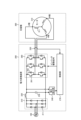
- FIG. 1 is a first diagram showing a configuration example of a power conversion device according to a first embodiment
- FIG. 2 is a second diagram showing a configuration example of a power conversion device according to the first embodiment
- FIG. 1 is a first diagram showing an example of pulsation in a power converter due to the capacitance of a smoothing capacitor and a reactor used in a typical power converter.
- FIG. 2 is a second diagram showing an example of pulsation in a power converter due to the capacitance of a smoothing capacitor and a reactor used in a typical power converter.
- FIG. 2 is a diagram showing a configuration example of a control unit included in the power conversion device according to the first embodiment;
- FIG. 13 is a diagram showing an example of an effect obtained by the control unit of the power conversion device according to the first embodiment controlling the operation of the inverter so as to suppress the amplitude amount of high-frequency components.
- FIG. 1 is a diagram showing an example of a hardware configuration for implementing a control unit included in a power conversion device according to a first embodiment
- FIG. 13 is a diagram showing a configuration example of a power conversion device according to a second embodiment and a control unit included in the power conversion device
- FIG. 13 is a diagram showing a configuration example of a control unit included in a power conversion device according to a third embodiment
- FIG. 1 is a diagram showing an example of a hardware configuration for implementing a control unit included in a power conversion device according to a first embodiment
- FIG. 13 is a diagram showing a configuration example of a power conversion device according to a second embodiment and a control unit included in the power conversion device
- FIG. 13 is a diagram showing a configuration example of a control unit included in a
- FIG. 13 is a diagram showing an operation of a control unit of a power conversion device according to a third embodiment for generating an inverter drive signal with a voltage command in a sine wave mode.
- FIG. 13 is a diagram showing an operation of a control unit of a power conversion device according to a third embodiment for generating an inverter drive signal with a voltage command in a trapezoidal wave mode.
- FIG. 13 is a diagram showing induced voltage characteristics of a motor of a compressor connected to a power conversion device according to a third embodiment.
- FIG. 13 is a diagram showing a configuration example of a flux-weakening control unit included in a control unit of a power conversion device according to a third embodiment; FIG.
- FIG. 13 is a diagram showing a configuration example of a DC component command unit further provided in a flux-weakening control unit provided in a control unit of a power conversion device according to a third embodiment
- FIG. 11 is a diagram showing a configuration example of a pulsating component command unit further provided in a flux-weakening control unit provided in a control unit of a power conversion device according to a third embodiment
- FIG. 11 is a diagram showing an example of a modulation rate correction table used in a PWM (Pulse Width Modulation) signal generating unit provided in a control unit of a power conversion device according to a third embodiment
- FIG. 13 is a diagram showing a configuration example of an air conditioner according to a fourth embodiment.
- Embodiment 1. 1 is a first diagram showing a configuration example of a power conversion device 200 according to a first embodiment.
- the power conversion device 200 is connected to an AC power source 100 and a compressor 300, converts an AC voltage output from the AC power source 100 into a DC voltage, and further converts the DC voltage into an AC voltage of a desired voltage and frequency, and outputs the DC voltage to the compressor 300.
- the AC voltage output from the AC power source 100 is referred to as a first AC voltage
- the AC voltage output from the power conversion device 200 is referred to as a second AC voltage.
- the power conversion device 200 includes a rectifier circuit 210, a reactor 220, a capacitor 230, a voltage detection unit 240, a current detection unit 250, an inverter 260, and a control unit 270.
- the rectifier circuit 210 includes a plurality of rectifier diodes 211, six diodes 211 in the example of FIG. 1, and converts the first AC voltage output from the AC power supply 100 into a first DC voltage and outputs it.
- the rectifier circuit 210 is a non-boosting type circuit.
- the rectifier circuit 210 is not a power factor correction circuit.
- one end of the reactor 220 is connected to the output end of the rectifier circuit 210, and the other end is connected to the capacitor 230. Note that the installation position of the reactor 220 within the power conversion device 200 is not limited to the example of FIG. 1.
- the capacitor 230 is a smoothing capacitor that smoothes the first DC voltage converted by the rectifier circuit 210 into a second DC voltage. It can also be said that the capacitor 230 smoothes the first DC voltage to generate the second DC voltage.
- the pulsating component contained in the second DC voltage is smaller than the pulsating component contained in the first DC voltage.
- a small smoothing capacitor i.e., a capacitor with a small capacity, is used.
- the capacitor 230 is, for example, an electrolytic capacitor, a film capacitor, or the like, but the type of the capacitor 230 is not limited to these.
- the voltage detection unit 240 is connected to the capacitor 230 and detects the DC bus voltage Vdc, which is the second DC voltage output from the capacitor 230.
- the voltage detection unit 240 has an RC filter with a time constant that serves as the cutoff frequency for frequency components higher than a specified multiple of the resonant frequency of the LC circuit of the reactor 220 and the capacitor 230, for example, frequency components that are 5 to 10 times higher, and detects the DC bus voltage Vdc using this RC filter.
- the voltage detection unit 240 outputs a detection value, which is the voltage value of the DC bus voltage Vdc, to the control unit 270.
- Inverter 260 is connected in parallel to capacitor 230, and under the control of control unit 270, converts DC bus voltage Vdc, which is a smoothed second DC voltage, into a second AC voltage of a desired voltage and frequency.
- inverter 260 includes switching element 261 and six diodes 262 connected in parallel to switching element 261.
- Inverter 260 turns on and off each switching element 261 based on an inverter drive signal, which is a PWM signal output from control unit 270, to generate a second AC voltage, i.e., converts DC bus voltage Vdc, which is a smoothed second DC voltage, into a second AC voltage.
- Inverter 260 outputs the second AC voltage to motor 310 included in compressor 300.
- Current detection unit 250 is connected between inverter 260 and motor 310, and detects current Iuvw output from inverter 260.
- Current Iuvw is a current flowing through each of the U-phase, V-phase, and W-phase layers of motor 310.
- Current detection unit 250 outputs a detection value, which is the current value of current Iuvw output from inverter 260, to control unit 270.
- current detection unit 250 may detect currents for two phases out of U-phase, V-phase, and W-phase if control unit 270 can calculate the current for the other phase from the currents for two phases.
- the control unit 270 controls the operation of the inverter 260 so as to output a second AC voltage to the motor 310 of the compressor 300 connected to the inverter 260. Specifically, the control unit 270 generates an inverter drive signal for controlling the operation of the inverter 260 based on the detection values acquired from the voltage detection unit 240 and the current detection unit 250, and outputs the signal to the inverter 260. Although not shown in FIG. 1, the control unit 270 may further control the operation of the inverter 260 using a detection value that is a current value detected by a current detection unit that detects the current flowing from the capacitor 230 to the inverter 260. The control unit 270 controls the operation of the inverter 260 using a dq rotating coordinate that rotates in synchronization with the rotor position of the motor 310, as described below.
- the compressor 300 connected to the power conversion device 200 includes a motor 310.
- the motor 310 is a three-phase motor that includes a winding 311 for each phase, i.e., the U phase, the V phase, and the W phase.
- FIG. 1 shows an example in which the AC power source 100 connected to the power conversion device 200 is a three-phase AC power source, but this is only an example and is not limited thereto.
- FIG. 2 is a second diagram showing an example of the configuration of the power conversion device 200 according to the first embodiment.
- the AC power source 100 connected to the power conversion device 200 may be a single-phase AC power source.
- the rectifier circuit 210 includes four diodes 211, and converts the first AC voltage output from the AC power source 100 into a first DC voltage and outputs it.
- one end of the reactor 220 is connected to the AC power source 100, and the other end is connected to the input end of the rectifier circuit 210. Note that, when the AC power source 100 is a single-phase AC power source, the installation position of the reactor 220 in the power conversion device 200 is not limited to the example of FIG. 2.
- the reactor 220 and capacitor 230 are often larger in size than the other electrical components.
- the power factor of the power conversion device 200 tends to deteriorate. Therefore, by reducing the capacity of the reactor 220 and capacitor 230, the power factor of the power conversion device 200 can be improved. Furthermore, by reducing the capacity of the reactor 220 and capacitor 230, the power conversion device 200 can have a smaller circuit, which can lead to cost reduction.
- the small smoothing capacitor 230 can be either an electrolytic capacitor or a film capacitor, and the type of capacitor is not important.
- the power conversion device 200 uses the circuit configuration described above, i.e., the rectifier circuit 210, the reactor 220, and the capacitor 230, to convert a first AC voltage into a first DC voltage, and then converts the first DC voltage into a second DC voltage, and uses the second DC voltage as the input voltage for the inverter 260.
- the second DC voltage pulsates at a frequency twice the number of power phases of the AC power supply 100, and the resonant frequency of the LC circuit formed by the reactor 220 and the capacitor 230 is superimposed.
- the resonant frequency F of the LC circuit formed by the reactor 220 and the capacitor 230 is a frequency that can be calculated by the following formula (1).
- L is the capacity of reactor 220
- C is the capacity of capacitor 230
- ⁇ (L ⁇ C) represents the square root of L ⁇ C.
- the capacity L of reactor 220 needs to be calculated including, for example, a DC reactor component, a wiring component, a noise filter component, a power supply reactor component, and the like.
- the resonant frequency F of the LC circuit becomes high frequency as the capacity of reactor 220 and capacitor 230 becomes small.
- FIG. 3 is a first diagram showing an example of pulsation in a power converter due to the capacity of a smoothing capacitor and the capacity of a reactor used in a general power converter.
- FIG. 4 is a second diagram showing an example of pulsation in a power converter due to the capacity of a smoothing capacitor and the capacity of a reactor used in a general power converter.
- FIG. 3 shows a case where the capacity of the capacitor is larger than that in the case of FIG. 4 and the capacity of the reactor is larger than that in the case of FIG. 4, and
- FIG. 4 shows a case where the capacity of the capacitor is smaller than that in the case of FIG. 3 and the capacity of the reactor is smaller than that in the case of FIG. 3.
- the first row shows the DC voltage, i.e., the bus voltage across the capacitor, the voltage in front of the reactor, and the power supply voltage of the power supply connected to the general power converter
- the second row shows the reactor current
- the third row shows the capacitor current
- the fourth row shows the power supply current of the power supply.
- the power conversion device 200 suppresses the high-frequency components of the power supply current of the AC power supply 100, which increase due to the small capacity of the reactor 220 and the capacitor 230, by controlling them using the pulsating components of the DC bus voltage Vdc.
- the detailed configuration and operation of the control unit 270 provided in the power conversion device 200 will be described.
- FIG. 5 is a diagram showing an example of the configuration of the control unit 270 provided in the power conversion device 200 according to the first embodiment. Note that the power conversion device 200 shown in FIG. 5 has some simplifications compared to the power conversion device 200 shown in FIG. 1.
- the control unit 270 includes a voltage adjustment unit 271, a pulsating component detection unit 272, a resonance suppression control unit 273, a voltage command control unit 274, a modulation rate calculation unit 275, and a PWM signal generation unit 276.
- the voltage adjustment unit 271 obtains the detection value of the DC bus voltage Vdc, which is the second DC voltage, from the voltage detection unit 240.
- the voltage adjustment unit 271 performs filtering on the DC bus voltage Vdc and outputs the filtered DC bus voltage Vdc to the pulsating component detection unit 272 and the modulation rate calculation unit 275.
- the voltage adjustment unit 271 may perform different filtering on the DC bus voltage Vdc output to the pulsating component detection unit 272 and the DC bus voltage Vdc output to the modulation rate calculation unit 275.
- the pulsating component detection unit 272 can more appropriately detect the pulsating component if it can use the instantaneous value of the DC bus voltage Vdc.
- the modulation rate calculation unit 275 uses the DC bus voltage Vdc to calculate the modulation rate, and therefore it is easier to calculate the modulation rate if the instantaneous fluctuations of the DC bus voltage Vdc are suppressed rather than if the DC bus voltage Vdc changes frequently. Therefore, the voltage adjustment unit 271 may perform filtering using a filter with a small time constant on the DC bus voltage Vdc output to the pulsating component detection unit 272, and may perform filtering using a filter with a time constant larger than the time constant for the pulsating component detection unit 272 on the DC bus voltage Vdc output to the modulation factor calculation unit 275.
- the voltage adjustment unit 271 may perform filtering using a filter with an extremely small time constant on the DC bus voltage Vdc output to the pulsating component detection unit 272, or may not perform filtering.
- the control unit 270 uses the instantaneous value of the second DC voltage in the detection of high-frequency components in the pulsating component detection unit 272 for the DC bus voltage Vdc, which is the second DC voltage detected by the voltage detection unit 240, and uses the value of the second DC voltage after passing through a filter to suppress instantaneous fluctuations in the calculation of the modulation factor in the modulation factor calculation unit 275.
- the pulsating component detection unit 272 acquires the filtered DC bus voltage Vdc from the voltage adjustment unit 271.
- the pulsating component detection unit 272 detects high-frequency components from the acquired filtered DC bus voltage Vdc, other than the frequency components twice the number of power supply phases of the AC power source 100.
- the pulsating component detection unit 272 performs Fourier series expansion on the acquired filtered DC bus voltage Vdc to extract the DC component and the frequency components twice the number of power supply phases of the AC power source 100.
- the pulsating component detection unit 272 detects high-frequency components contained in the acquired filtered DC bus voltage Vdc using the extracted DC component and the frequency components twice the number of power supply phases of the AC power source 100.
- the high-frequency components acquired by the detection are mainly composed of the components of the resonant frequency F of the LC circuit formed by the reactor 220 and the capacitor 230.
- the pulsating component detection unit 272 can also detect high-frequency components using a method other than Fourier series expansion.
- the pulsating component detection unit 272 may detect high-frequency components using a filter such as a band-pass filter.
- the pulsating component detection unit 272 outputs the detected high-frequency components to the resonance suppression control unit 273 as the high-frequency component Vdc_ripple.
- the resonance suppression control unit 273 acquires the high frequency component Vdc_ripple from the pulsating component detection unit 272.
- the resonance suppression control unit 273 calculates a control amount that cancels the high frequency component Vdc_ripple.
- the resonance suppression control unit 273 may calculate the control amount using general proportional control, differential control, proportional differential control, etc., as a method for calculating the control amount as described above, or may calculate the control amount using a filter that advances the phase instead of these controls.
- the resonance suppression control unit 273 outputs the control amount obtained by the calculation to the modulation factor calculation unit 275 as the control amount V_ripple * .
- the voltage command control unit 274 acquires the current Iuvw output from the inverter 260 from the current detection unit 250.
- the voltage command control unit 274 estimates the position of a rotor (not shown) of the motor 310 based on the current Iuvw. This is because, when the power conversion device 200 is used in an air conditioner or the like, position sensorless control is often performed without using a position sensor that detects the position of the rotor of the motor 310 for the compressor 300.
- the voltage command control unit 274 estimates an estimated phase angle ⁇ , which is the direction of the rotor magnetic pole in the dq axis, and an estimated speed ⁇ , which is the rotor speed, for the rotor.
- the voltage command control unit 274 generates a first voltage command V * based on the speed command ⁇ * and the estimated speed ⁇ . Specifically, the voltage command control unit 274 automatically adjusts the first voltage command V * so that the speed command ⁇ * and the estimated speed ⁇ match.
- the speed command ⁇ * is based on, for example, a temperature detected by a temperature sensor (not shown), information indicating a set temperature instructed from a remote control (not shown), which is an operation unit, information on the selection of an operation mode, and information on instruction to start and end operation.
- the operation mode is, for example, heating, cooling, dehumidification, etc.
- the voltage command control unit 274 outputs the estimated phase angle ⁇ to the PWM signal generation unit 276, and outputs the first voltage command V * to the modulation factor calculation unit 275.
- the modulation factor calculation unit 275 obtains the filtered DC bus voltage Vdc from the voltage adjustment unit 271, obtains the control amount V_ripple * from the resonance suppression control unit 273, and obtains the first voltage command V * from the voltage command control unit 274.
- the modulation factor calculation unit 275 calculates the modulation factor Kh in the power conversion device 200 by the following equation (2).
- ⁇ (Vd *2 +Vq *2 ) represents the square root of Vd *2 +Vq *2
- ⁇ (2) represents the square root of 2.
- the modulation factor calculation unit 275 calculates the second voltage command V ** by the following formula (3).
- V ** V * +V_ripple * ...(3)
- the modulation factor calculation unit 275 outputs the calculated modulation factor Kh and the second voltage command V ** to the PWM signal generation unit 276 .
- the PWM signal generating unit 276 obtains the estimated phase angle ⁇ from the voltage command control unit 274, and obtains the modulation factor Kh and the second voltage command V ** from the modulation factor calculation unit 275.
- the PWM signal generating unit 276 performs coordinate conversion of the second voltage command V ** from the dq coordinate to the AC voltage command Vuvw * according to the estimated phase angle ⁇ .
- the PWM signal generating unit 276 generates a PWM signal based on the modulation factor Kh and the coordinate-converted voltage command Vuvw * .
- the control unit 270 applies a voltage to the motor 310 by outputting the PWM signal generated by the PWM signal generating unit 276 to the switching element 261 of the inverter 260 as the inverter drive signal described above.
- the control unit 270 detects high-frequency components from the DC bus voltage Vdc, which is the second DC voltage, other than the frequency components twice the number of power supply phases of the AC power supply 100, and controls the operation of the inverter 260 to suppress the amplitude of the high-frequency components.
- the control unit 270 can also control the high-frequency components of the power supply current.
- Figure 6 is a diagram showing an example of the effect obtained by the control unit 270 of the power conversion device 200 according to embodiment 1 controlling the operation of the inverter 260 to suppress the amplitude of the high-frequency components.
- the upper row shows the power supply current flowing between the AC power supply 100 and the power conversion device 200, and the lower row shows the DC bus voltage Vdc, which is the second DC voltage.
- the control unit 270 controls the operation of the inverter 260 to suppress the amplitude of the high-frequency components, thereby reducing the high-frequency components contained in the power supply current from the AC power supply 100 and reducing the high-frequency components contained in the DC bus voltage Vdc, which is the second DC voltage.
- the control unit 270 does not perform control to suppress the amplitude of the frequency component of the power supply frequency f of the AC power supply 100 times the number of power supply phases ⁇ 2. Therefore, after the control unit 270 starts the above-mentioned control, the pulsation contained in the DC bus voltage Vdc, which is the second DC voltage, is mainly frequency components of the power supply frequency f of the AC power supply 100 times the number of power supply phases ⁇ 2.
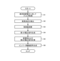
- FIG. 7 is a flowchart showing the operation of the control unit 270 of the power conversion device 200 according to the first embodiment.
- the voltage adjustment unit 271 performs a filter process on the DC bus voltage Vdc, which is the second DC voltage acquired from the voltage detection unit 240 (step S1).
- the ripple component detection unit 272 detects a high-frequency component Vdc_ripple other than the frequency component twice the number of power supply phases of the AC power source 100 among the AC components from the DC bus voltage Vdc after the filter process (step S2).
- the resonance suppression control unit 273 calculates a control amount V_ripple * that cancels out the high-frequency component Vdc_ripple (step S3).
- the voltage command control unit 274 estimates an estimated phase angle ⁇ , which is the direction of the rotor magnetic poles on the dq axis, and an estimated speed ⁇ based on the current Iuvw, and generates a first voltage command V * based on the speed command ⁇ * and the estimated speed ⁇ (step S4).
- the modulation factor calculation unit 275 calculates a modulation factor Kh from the filtered DC bus voltage Vdc and the first voltage command V * , and calculates a second voltage command V ** from the first voltage command V * and the controlled variable V_ripple * (step S5).
- the PWM signal generation unit 276 generates an inverter drive signal, which is a PWM signal, based on the estimated phase angle ⁇ , the second voltage command V ** , and the modulation factor Kh (step S6).
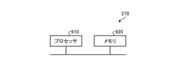
- FIG. 8 is a diagram showing an example of a hardware configuration that realizes the control unit 270 included in the power conversion device 200 according to the first embodiment.
- the control unit 270 is realized by a processor 910 and a memory 920.
- the processor 910 is a CPU (Central Processing Unit, also known as a central processing unit, processing unit, arithmetic unit, microprocessor, microcomputer, processor, or DSP (Digital Signal Processor)) or a system LSI (Large Scale Integration).
- Examples of memory 920 include non-volatile or volatile semiconductor memories such as RAM (Random Access Memory), ROM (Read Only Memory), flash memory, EPROM (Erasable Programmable Read Only Memory), and EEPROM (registered trademark) (Electrically Erasable Programmable Read Only Memory).
- Memory 920 is not limited to these, and may also be a magnetic disk, optical disk, compact disk, mini disk, or DVD (Digital Versatile Disc).
- the control unit 270 detects high-frequency components from the DC bus voltage Vdc, which is the second DC voltage, among the AC components, other than the frequency components with twice the number of power supply phases of the AC power supply 100, and controls the operation of the inverter 260 to suppress the amplitude of the high-frequency components.
- the control unit 270 can suppress high-frequency components such as the resonant frequency F of the LC circuit formed by the reactor 220 and the capacitor 230, which are included in the DC bus voltage Vdc, which is the second DC voltage, while reducing the calculation load.
- the control unit 270 can suppress high-frequency components included in the power supply current from the AC power supply 100.
- Embodiment 2 a method of detecting high-frequency components with higher accuracy than in the first embodiment will be described when the pulsating component detection unit 272 of the control unit 270 detects high-frequency components using Fourier series expansion.
- FIG. 9 is a diagram showing an example of the configuration of a power conversion device 200 according to the second embodiment and a control unit 270 provided in the power conversion device 200.
- the power conversion device 200 of the second embodiment shown in FIG. 9 is obtained by adding a phase detection unit 255 to the power conversion device 200 of the first embodiment shown in FIG. 5.
- the control unit 270 of the second embodiment shown in FIG. 9 is obtained by adding a phase calculation unit 277 to the control unit 270 of the first embodiment shown in FIG. 5.
- the phase detection unit 255 is connected between the AC power supply 100 and the rectifier circuit 210, and detects the phase of the first AC voltage output from the AC power supply 100.
- the phase detection unit 255 outputs information about the detected phase to the phase calculation unit 277 of the control unit 270.
- the phase calculation unit 277 acquires information on the phase of the first AC voltage output from the AC power supply 100 from the phase detection unit 255. Based on the acquired phase information, the phase calculation unit 277 detects frequency components that indicate the frequency components at which the first AC voltage output from the AC power supply 100 is pulsating, i.e. fluctuating. The phase calculation unit 277 outputs the detected frequency components to the pulsating component detection unit 272 as frequency component ⁇ vac_6f.
- the pulsating component detection unit 272 acquires the frequency component ⁇ vac_6f from the phase calculation unit 277.
- the pulsating component detection unit 272 uses the acquired frequency component ⁇ vac_6f to perform a Fourier series expansion of the filtered DC bus voltage Vdc acquired from the voltage adjustment unit 271.
- the pulsating component detection unit 272 can grasp the frequency component at which the first AC voltage output from the AC power supply 100 pulsates, i.e., fluctuates, by using the frequency component ⁇ vac_6f, and can therefore detect high frequency components with higher accuracy by performing a Fourier series expansion based on the frequency component ⁇ vac_6f, compared to the first embodiment in which the frequency component ⁇ vac_6f is not used.
- control unit 270 uses information on the frequency component ⁇ vac_6f for the first AC voltage output from the AC power supply 100.
- Other operations of the control unit 270 in the second embodiment are similar to those of the control unit 270 in the first embodiment.
- the control unit 270 uses information on the frequency component ⁇ vac_6f for the first AC voltage output from the AC power supply 100 when detecting high-frequency components in the pulsating component detection unit 272. This allows the control unit 270 to improve the accuracy of the Fourier series expansion in the pulsating component detection unit 272 compared to the first embodiment.
- Embodiment 3 In the third embodiment, a case will be described in which the control unit 270 performs flux-weakening control in the case of overmodulation in which the modulation rate Kh is greater than 1.0.
- FIG. 10 is a diagram showing an example of the configuration of a control unit 270 provided in a power conversion device 200 according to embodiment 3.
- the control unit 270 according to embodiment 3 shown in FIG. 10 is obtained by adding a flux-weakening control unit 278 to the control unit 270 according to embodiment 1 shown in FIG. 5.
- control unit 270 When the control unit 270 controls the operation of the inverter 260 will be described.
- the control unit 270 In the power conversion device 200, the control unit 270 generates an inverter drive signal for controlling the on/off of the switching elements 261 corresponding to each phase based on the result of comparing the voltage command for each phase with the carrier, in order to control the on/off of each switching element 261 of the inverter 260.
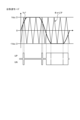
- FIG. 11 is a diagram showing an operation in which the control unit 270 of the power conversion device 200 according to the third embodiment generates inverter drive signals UP and UN with a voltage command in a sine wave mode.
- FIG. 11 is a diagram showing a case in which the voltage command Vu * is in the sine wave mode, and the maximum amplitude of the voltage command Vu * is Vdc/2.
- the control unit 270 compares the voltage command Vu * for the U phase with the carrier.
- the control unit 270 When the carrier is larger than the voltage command Vu * , the control unit 270 generates each inverter drive signal so that the inverter drive signal UP for the switching element 261 of the upper arm of the U phase is high and the inverter drive signal UN for the switching element 261 of the lower arm of the U phase is low.
- the control unit 270 When the voltage command Vu * is larger than the carrier, the control unit 270 generates each inverter drive signal so that the inverter drive signal UP for the switching element 261 of the upper arm of the U phase is low and the inverter drive signal UN for the switching element 261 of the lower arm of the U phase is high.
- control unit 270 similarly generates an inverter drive signal VP for the upper arm switching element 261 of the V phase and an inverter drive signal VN for the lower arm switching element 261 of the V phase based on a result of comparing a voltage command Vv * for the V phase with the carrier.
- the control unit 270 also generates an inverter drive signal WP for the upper arm switching element 261 of the W phase and an inverter drive signal WN for the lower arm switching element 261 of the W phase based on a result of comparing a voltage command Vw* for the W phase with the carrier.
- the voltage command is not limited to a sine wave shape.
- Fig. 12 is a diagram showing an operation in which the control unit 270 of the power conversion device 200 according to the third embodiment generates the inverter drive signals UP and UN with a voltage command in a trapezoidal wave mode.
- Fig. 12 is a diagram showing a case in which the voltage command Vu * is in a trapezoidal wave mode, and the maximum amplitude of the voltage command Vu * is Vdc/2.
- the control unit 270 generates inverter drive signals for the switching elements 261 of the upper and lower arms of each phase based on the result of comparing the voltage command for each phase with the carrier.
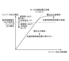
- FIG. 13 is a diagram showing the induced voltage characteristics of motor 310 of compressor 300 connected to power conversion device 200 according to embodiment 3.
- the horizontal axis shows the inverter output frequency, which is the frequency of the second AC voltage that is the output voltage of inverter 260
- the vertical axis shows the output voltage of inverter 260.
- the induced voltage constant of motor 310 based on the output voltage of inverter 260 and the output frequency of inverter 260 is shown as the induced voltage characteristics of motor 310.
- control unit 270 can control the output voltage of inverter 260 according to the induced voltage constant of motor 310 when the output voltage of inverter 260 is in the non-overmodulation range, i.e., in the sine wave mode with a modulation rate of 1.0 or less.
- the control unit 270 is unable to control the output voltage of the inverter 260 according to the induced voltage constant of the motor 310.
- control unit 270 can control the output voltage of inverter 260 to the desired voltage and frequency according to the induced voltage constant of motor 310 by using the sine wave mode voltage command shown in FIG. 11.
- control unit 270 uses the trapezoidal wave mode voltage command shown in FIG. 12, but is unable to control the output voltage of inverter 260 to the desired voltage and frequency according to the induced voltage constant of motor 310, resulting in saturation regardless of the inverter output frequency. In such cases, problems such as vibration and noise occur in compressor 300.
- the first DC voltage output from the rectifier circuit 210 is smoothed by the smoothing capacitor 230, so the pulsation of the DC bus voltage Vdc, which is the second DC voltage after smoothing, is determined by the capacity of the capacitor 230. If the capacity of the capacitor 230 is large, the pulsation of the DC bus voltage Vdc is small, so the DC bus voltage Vdc, i.e., the voltage supplied to the inverter 260, is stable. However, if a capacitor 230 with a large capacity is used, the power conversion device 200 has problems such as adverse effects such as worsening the power factor of the input current and increasing the power supply high frequency, increasing the product size, and increasing costs.
- the reactor 220 and the capacitor 230 are often larger in size than other electrical components.
- the above-mentioned problems are solved by using a reactor 220 and a capacitor 230 with a small capacity, but in the power conversion device 200, the pulsation amount of the DC bus voltage Vdc increases.
- the pulsation amount of the DC bus voltage Vdc varies depending on the capacity of the capacitor 230, but the component that pulsates with a period twice the number of power supply phases of the AC power supply 100 is the most dominant.
- the resonance frequency F of the LC circuit formed by the reactor 220 and the capacitor 230 becomes high frequency, and in the power conversion device 200, the DC bus voltage Vdc including such pulsation is supplied to the inverter 260.
- the inverter 260 generates an AC voltage of a desired frequency and voltage using the DC bus voltage Vdc including pulsation and applies the voltage to the motor 310, so the smaller the capacity of the capacitor 230, the greater the influence on the motor control.
- the control of the inverter 260 in the power conversion device 200 is roughly divided into two voltage output patterns, a sine wave mode and a trapezoidal wave mode.
- the output voltage has a margin relative to the DC bus voltage Vdc input to the inverter 260, so the effect on the output voltage of the inverter 260 is small, and the effect on the motor 310 is also small.
- the trapezoidal wave mode the second voltage command V ** generated by the control unit 270 is not proportional to the inverter output voltage, so that the trapezoidal wave mode is likely to affect the operation of the motor 310.
- the inverter output voltage is not constant in the trapezoidal wave mode, so that the motor phase current pulsates at a low frequency, the rotation speed of the motor 310 fluctuates, and other conditions occur.
- the motor phase current pulsates, the current peak value increases even if the effective current value remains the same, and therefore, particularly near the operating limit of the power conversion device 200, a state occurs in which the current peak value of the motor phase current exceeds the irreversible demagnetization current of the motor 310 using a highly efficient permanent magnet, or exceeds the overcurrent value of the inverter 260, leading to failures of the inverter 260 and the motor 310.
- fluctuations in the rotation speed of the motor 310 mean speed fluctuations in the motor 310, the mechanism in which the motor 310 is mounted, for example, the compressor 300 mounted in an air conditioner (not shown), vibrates, causing noise, failures, and the like.
- control unit 270 performs flux-weakening control in the case of overmodulation where the modulation rate Kh is greater than 1.0.
- the voltage adjusting unit 271 further outputs the filtered DC bus voltage Vdc, which is output to the modulation factor calculating unit 275, to the flux-weakening control unit 278.
- the modulation factor calculating unit 275 further outputs the modulation factor Kh and the second voltage command V ** , which are output to the PWM signal generating unit 276, to the flux-weakening control unit 278.
- the flux-weakening control unit 278 determines not to perform flux-weakening control when the modulation factor Kh acquired from the modulation factor calculation unit 275 is in the sine wave mode in the range of 0 to 1.0, and determines to perform flux-weakening control when the modulation factor Kh acquired from the modulation factor calculation unit 275 is in the trapezoidal wave mode in the range greater than 1.0.
- the flux-weakening control unit 278 performs flux-weakening control using the filtered DC bus voltage Vdc acquired from the voltage adjustment unit 271 and the second voltage command V ** acquired from the modulation factor calculation unit 275.
- the detailed configuration and operation of the flux-weakening control unit 278 will be described.
- FIG. 14 is a diagram showing an example of the configuration of a flux-weakening control unit 278 provided in the control unit 270 of the power conversion device 200 according to the third embodiment.
- the flux-weakening control unit 278 includes a DC component command unit 280, a pulsating component command unit 290, and an adder unit 299.
- the flux-weakening control unit 278 includes one pulsating component command unit 290, but it is also possible to include two or more pulsating component command units 290.
- the flux-weakening control unit 278 includes the same number of adders 299 as the number of pulsating component command units 290.
- the flux-weakening control unit 278 detects a DC component and a pulsation component from a differential voltage, which is a voltage difference between the DC bus voltage Vdc and the second voltage command V ** , and performs flux-weakening control on the detected DC component and pulsation component.
- the DC bus voltage Vdc corresponds to the inverter input voltage
- the second voltage command V ** corresponds to the inverter output voltage.
- the flux-weakening control unit 278 detects a DC component and a pulsation component from a differential voltage, which is a voltage difference between the inverter input voltage input to the inverter 260 and the inverter output voltage output from the inverter 260, and performs flux-weakening control on the DC component and the pulsation component.
- FIG. 15 is a diagram showing an example of the configuration of a DC component command unit 280 further provided in a flux-weakening control unit 278 provided in a control unit 270 of a power conversion device 200 according to embodiment 3.
- the DC component command unit 280 includes a control amount calculation unit 283.
- the control amount calculation unit 283 calculates a control amount by controlling a DC component of a differential voltage, which is a voltage difference between the DC bus voltage Vdc and the second voltage command V ** , as a control object.
- a method of calculating the control amount in the control amount calculation unit 283 for example, a method using integral control can be used to achieve both controllability and stability.
- the control amount calculation unit 283 may perform proportional control, differential control, etc. in addition to integral control.
- the control amount calculation unit 283 may also perform limiter processing based on a specified value.
- the control amount calculation unit 283 outputs the calculated control amount as a d-axis current command Id * for the DC component to be controlled.
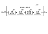
- FIG. 16 is a diagram showing an example of the configuration of a pulsating component command unit 290 further provided in a flux weakening control unit 278 provided in a control unit 270 of a power conversion device 200 according to embodiment 3.
- the pulsating component command unit 290 includes a pulsating extraction unit 291, a DC conversion unit 292, a control amount calculation unit 293, and an AC conversion unit 294.
- the pulsation extraction unit 291 extracts a pulsation component of a specified frequency, that is, a pulsation component of a specific frequency to be controlled by the pulsation component command unit 290. For example, the pulsation extraction unit 291 multiplies a differential voltage, which is a voltage difference between the DC bus voltage Vdc and the second voltage command V ** , by a cosine cos ⁇ x of the frequency component ⁇ x to be controlled. The pulsation extraction unit 291 also multiplies a differential voltage, which is a voltage difference between the DC bus voltage Vdc and the second voltage command V ** , by a sine sin ⁇ x of the frequency component ⁇ x to be controlled. The pulsation extraction unit 291 can extract a pulsation component of a specific frequency to be controlled by a Fourier series expansion calculation.
- the flux-weakening control unit 278 can include a plurality of pulsating component command units 290 as described above. Therefore, the pulsating extraction unit 291 of a certain pulsating component command unit 290 extracts, for example, a pulsating component of the power frequency of the AC power supply 100. Also, the pulsating extraction unit 291 of another pulsating component command unit 290 extracts, for example, a pulsating component of an n-fold frequency based on the power frequency, number of power phases, etc. of the AC power supply 100. Note that n is a positive integer of 2 or more.
- the flux-weakening control unit 278 includes two or more pulsating component command units 290, one pulsating component command unit 290 extracts a pulsating component of the power frequency of the AC power supply 100, and the other pulsating component command unit 290 extracts a pulsating component of an n-fold frequency based on the power frequency, number of power phases, etc. of the AC power supply 100, thereby making it possible to perform flux-weakening control more effectively.
- the flux-weakening control unit 278 can detect pulsating components of two or more different frequencies when detecting a pulsating component of a specific frequency to be controlled from a differential voltage, which is the voltage difference between the inverter input voltage input to the inverter 260 and the inverter output voltage output from the inverter 260.
- the DC converter 292 converts the pulsating component obtained by the pulsating extraction unit 291 into a DC amount.
- the DC converter 292 converts the pulsating component into a DC amount by separately treating, for example, the cos ⁇ x component of the pulsating component obtained by multiplying the differential voltage by the cosine cos ⁇ x of the frequency component ⁇ x of the control target, and the sin ⁇ x component of the pulsating component obtained by multiplying the differential voltage by the sine sin ⁇ x of the frequency component ⁇ x of the control target, both obtained by the pulsating extraction unit 291.
- the DC converter 292 can convert the pulsating component into a DC amount by using, for example, a first-order lag filter, without increasing the computational load.
- the control amount calculation unit 293 controls the DC amount to calculate the control amount at a specific frequency to be controlled. For example, the control amount calculation unit 293 calculates the control amount by separately handling the DC amount of the cos ⁇ x component of the pulsating component obtained by the DC conversion unit 292 and the DC amount of the sin ⁇ x component of the pulsating component. Regarding the method of calculating the control amount in the control amount calculation unit 293, for example, a method using integral control can be used to achieve both controllability and stability.
- the control amount calculation unit 293 may perform proportional control, differential control, etc. in addition to integral control.
- the control amount calculation unit 293 may also perform limiter processing based on a specified value.
- the control amount calculation unit 293 can ensure the stability of control in the flux-weakening control unit 278 by performing control similar to that of the control amount calculation unit 283 of the DC component command unit 280 described above.
- the AC converter 294 converts the control amount calculated by the control amount calculator 293 into an AC amount. For example, the AC converter 294 multiplies the control amount based on the DC amount of the cos ⁇ x component of the pulsating component by the cosine cos ⁇ x of the frequency component ⁇ x to be controlled, and converts the DC component back to an AC component. The AC converter 294 also multiplies the control amount based on the DC amount of the sin ⁇ x component of the pulsating component by the sine sin ⁇ x of the frequency component ⁇ x to be controlled, and converts the DC component back to an AC component. The AC converter 294 then adds the two values converted back to AC components, and generates and outputs a d-axis current command Id * for the frequency component ⁇ x to be controlled.
- the pulsating component command unit 290 the pulsating extraction unit 291, the DC conversion unit 292, the control amount calculation unit 293, and the AC conversion unit 294 handle the frequency component ⁇ x to be controlled by dividing it into a cosine component and a sine component, but this is just one example, and other control methods may be used.
- the adder 299 adds the d-axis current command Id * output from the DC component command unit 280 and the pulsating component command unit 290, and outputs the summed d-axis current command Id * to the voltage command control unit 274 as the d-axis current command Id * from the flux-weakening control unit 278.
- control unit 270 extracts a DC component and a pulsating component from a differential voltage, which is a difference voltage between DC bus voltage Vdc, which is the second DC voltage, and second voltage command V ** obtained in the process of generating an inverter drive signal for inverter 260, and performs flux-weakening control on the DC component and the pulsating component.
- the control unit 270 makes the response frequency of the control of the flux-weakening control unit 278 sufficiently smaller by about 5 to 20 times than the response frequency of the control of the voltage command control unit 274.
- the control unit 270 makes the response frequency of the control for calculating the second voltage command V**, which is a command value when generating an inverter drive signal, which is a PWM signal for the inverter 260, in the voltage command control unit 274, larger by 5 to 20 times than the response frequency of the flux- weakening control to the DC component and the response frequency of the flux-weakening control to the pulsating component in the flux-weakening control unit 278.
- control unit 270 makes it possible for the control unit 270 to avoid control interference between the flux-weakening control unit 278 and the voltage command control unit 274, to fully obtain the effect of the flux-weakening control, to maintain the stability of the control, and to more effectively obtain effects such as suppressing fluctuations in the current peak value of the motor phase current.
- the control unit 270 also makes the response frequency of the flux-weakening control for the DC component and the response frequency of the flux-weakening control for the pulsating component the same.
- the control unit 270 makes the control responsiveness of the control amount calculation unit 283 on the DC component side and the control responsiveness of the control amount calculation unit 293 on the pulsating component side the same, thereby maintaining control stability and more effectively suppressing fluctuations in the current peak value of the motor phase current.
- control unit 270 performs flux-weakening control using both the DC component and the pulsating component of the differential voltage, which is the voltage of the difference between the DC bus voltage Vdc and the second voltage command V ** .
- a sensor-based control using a sensor capable of detecting the magnet position of the motor 310 may be performed, but the effect of flux-weakening control can also be obtained in sensorless control in which the magnet position of the motor 310 cannot be detected by a sensor.
- the control unit 270 can obtain a greater control effect of flux-weakening control by using a control method capable of estimating the magnet position of the motor 310 with high accuracy, such as observer control.
- the control unit 270 estimates the magnet position of the motor 310 using a control method capable of estimating the magnet position of the motor 310 with an accuracy equal to or higher than a specified accuracy, and performs flux-weakening control. Since the control unit 270 can more appropriately determine the magnet phase of the motor 310, i.e., the d-axis, the effect of suppressing the current peak value of the motor phase current by the flux-weakening control of the third embodiment can be easily obtained.
- the power conversion device 200 can expand the operating range to the level when the reactor 220 and the smoothing capacitor 230 have a large capacity, even when the capacity of the reactor 220 and the capacitor 230 is small.
- the power conversion device 200 can improve the control responsiveness of the flux-weakening control in trapezoidal wave mode even if the DC bus voltage Vdc, which is the input voltage of the inverter 260, is insufficient, thereby achieving stable motor control and suppressing fluctuations in the current peak value of the motor phase current.
- the PWM signal generating unit 276 can also change the control content according to the modulation rate Kh.
- the modulation factor Kh indicates the ratio between the voltage input to the inverter 260 and the voltage output from the inverter 260.
- the modulation factor Kh and the inverter output voltage have a linearity that increases proportionally, but in the trapezoidal wave mode where the modulation factor Kh is in the range of more than 1.0, the relationship between the modulation factor Kh and the inverter output voltage has a nonlinear characteristic.
- the PWM signal generating unit 276 uses a modulation factor correction table that tabulates the relationship between the modulation factor Kh and the voltage value of the inverter output voltage, thereby increasing the responsiveness of the inverter output voltage in the range where the modulation factor Kh is greater than 1.0, and improving the responsiveness without changing the characteristics of the current control.
- the control unit 270 uses a modulation factor correction table that indicates the relationship between the inverter output voltage and the modulation factor Kh in controlling the operation of the inverter 260 in the overmodulation region where the modulation factor Kh exceeds 1.0.
- FIG. 17 is a diagram showing an example of a modulation factor correction table used by the PWM signal generating unit 276 included in the control unit 270 of the power conversion device 200 according to the third embodiment.
- the horizontal axis shows the voltage fundamental wave component ratio indicating the voltage value of the inverter output voltage
- the vertical axis shows the modulation factor correction coefficient K for correcting the modulation factor Kh.
- the PWM signal generating unit 276 can perform control by correcting the solid line characteristics shown in FIG. 13 to the dotted line characteristics.
- the control unit 270 performs flux-weakening control in the overmodulation region when the operation mode is the trapezoidal wave mode. This allows the control unit 270 to suppress high-frequency components contained in the DC bus voltage Vdc while ensuring the output voltage of the inverter 260.
- FIG. 18 is a diagram showing a configuration example of an air conditioner 500 according to embodiment 4.
- the air conditioner 500 includes an AC power source 100, a power conversion device 200, a compressor 300 having a motor 310, a four-way valve 400, an outdoor heat exchanger 410, an expansion valve 420, an indoor heat exchanger 430, and a refrigerant pipe 440.
- the compressor 300, the four-way valve 400, the outdoor heat exchanger 410, the expansion valve 420, and the indoor heat exchanger 430 are connected via the refrigerant pipe 440.
- a motor 310 that operates a compressor mechanism (not shown) is provided inside the compressor 300.
- the motor 310 has a configuration having a stator and a rotor.
- the motor 310 is a compressor motor that is driven by inputting a second AC voltage having a desired voltage and frequency generated by the power conversion device 200.
- the air conditioner 500 can perform air conditioning control by compressing the refrigerant inside the compressor 300 as a result of the rotation of the motor 310 inside the compressor 300, and circulating the refrigerant between the outdoor heat exchanger 410 and the indoor heat exchanger 430 via the refrigerant piping 440.
- the power conversion device 200 and the motor 310 are electrically connected, and the power conversion device 200 is connected to the AC power source 100.
- the power conversion device 200 generates an AC voltage to be supplied to the motor 310 by using a first AC voltage supplied from the AC power source 100.
- the power conversion device 200 is mounted on the air conditioner 500, but this is just one example and is not limiting.
- the power conversion device 200 can be applied to products equipped with a refrigeration cycle, such as refrigerators, freezers, and heat pump water heaters.
Landscapes
- Engineering & Computer Science (AREA)
- Power Engineering (AREA)
- Inverter Devices (AREA)
Priority Applications (2)
| Application Number | Priority Date | Filing Date | Title |
|---|---|---|---|
| JP2025504898A JPWO2024184960A1 (https=) | 2023-03-03 | 2023-03-03 | |
| PCT/JP2023/008055 WO2024184960A1 (ja) | 2023-03-03 | 2023-03-03 | 電力変換装置および空気調和機 |
Applications Claiming Priority (1)
| Application Number | Priority Date | Filing Date | Title |
|---|---|---|---|
| PCT/JP2023/008055 WO2024184960A1 (ja) | 2023-03-03 | 2023-03-03 | 電力変換装置および空気調和機 |
Publications (1)
| Publication Number | Publication Date |
|---|---|
| WO2024184960A1 true WO2024184960A1 (ja) | 2024-09-12 |
Family
ID=92674442
Family Applications (1)
| Application Number | Title | Priority Date | Filing Date |
|---|---|---|---|
| PCT/JP2023/008055 Ceased WO2024184960A1 (ja) | 2023-03-03 | 2023-03-03 | 電力変換装置および空気調和機 |
Country Status (2)
| Country | Link |
|---|---|
| JP (1) | JPWO2024184960A1 (https=) |
| WO (1) | WO2024184960A1 (https=) |
Citations (4)
| Publication number | Priority date | Publication date | Assignee | Title |
|---|---|---|---|---|
| JP2006271146A (ja) * | 2005-03-25 | 2006-10-05 | Matsushita Electric Ind Co Ltd | インバータ装置 |
| JP2012075226A (ja) * | 2010-09-28 | 2012-04-12 | Hitachi Ltd | 鉄道車両用電力変換装置および鉄道システム |
| JP2019083682A (ja) * | 2017-10-30 | 2019-05-30 | ダイキン工業株式会社 | 電力変換装置 |
| WO2022172419A1 (ja) * | 2021-02-12 | 2022-08-18 | 三菱電機株式会社 | 電力変換装置、モータ駆動装置および空気調和機 |
-
2023
- 2023-03-03 JP JP2025504898A patent/JPWO2024184960A1/ja active Pending
- 2023-03-03 WO PCT/JP2023/008055 patent/WO2024184960A1/ja not_active Ceased
Patent Citations (4)
| Publication number | Priority date | Publication date | Assignee | Title |
|---|---|---|---|---|
| JP2006271146A (ja) * | 2005-03-25 | 2006-10-05 | Matsushita Electric Ind Co Ltd | インバータ装置 |
| JP2012075226A (ja) * | 2010-09-28 | 2012-04-12 | Hitachi Ltd | 鉄道車両用電力変換装置および鉄道システム |
| JP2019083682A (ja) * | 2017-10-30 | 2019-05-30 | ダイキン工業株式会社 | 電力変換装置 |
| WO2022172419A1 (ja) * | 2021-02-12 | 2022-08-18 | 三菱電機株式会社 | 電力変換装置、モータ駆動装置および空気調和機 |
Also Published As
| Publication number | Publication date |
|---|---|
| JPWO2024184960A1 (https=) | 2024-09-12 |
Similar Documents
| Publication | Publication Date | Title |
|---|---|---|
| CN109463040B (zh) | 电动机驱动装置以及制冷设备 | |
| CN107852120B (zh) | 电力转换装置以及电动机驱动装置、制冷装置 | |
| JP6180635B2 (ja) | 電力変換装置、除湿機、空調装置および冷凍装置 | |
| JP6368664B2 (ja) | アクティブフィルタ、及びそれを用いたモータ駆動装置、並びに冷凍装置 | |
| JPWO2019142301A1 (ja) | 駆動装置、流体利用装置及び空気調和機 | |
| WO2023073880A1 (ja) | 電力変換装置、モータ駆動装置および冷凍サイクル適用機器 | |
| CN118266161A (zh) | 电力转换装置、马达驱动装置以及制冷循环应用设备 | |
| JP7566175B2 (ja) | 電力変換装置、電動機駆動装置及び冷凍サイクル適用機器 | |
| CN116802982A (zh) | 电力转换装置 | |
| WO2023073870A1 (ja) | 電力変換装置、モータ駆動装置および冷凍サイクル適用機器 | |
| JP2015042010A (ja) | モータ駆動装置、モータ駆動モジュール、圧縮機及びこれを備えた冷凍装置 | |
| CN118339759A (zh) | 电力转换装置、马达驱动装置以及制冷循环应用设备 | |
| WO2023157045A1 (ja) | 電力変換装置および空気調和機 | |
| WO2024184960A1 (ja) | 電力変換装置および空気調和機 | |
| JP2018109859A (ja) | 制御装置、電力変換装置、モータ駆動装置、及び、それを用いた冷凍機器 | |
| JP7566174B2 (ja) | 電力変換装置、電動機駆動装置及び冷凍サイクル適用機器 | |
| JP7595807B2 (ja) | モータ駆動装置及び冷凍サイクル装置 | |
| JP7330401B2 (ja) | 電力変換装置、モータ駆動装置および冷凍サイクル適用機器 | |
| JP7819347B2 (ja) | 電力変換装置、モータ駆動装置および冷凍サイクル適用機器 | |
| WO2023047486A1 (ja) | 電力変換装置、電動機駆動装置及び冷凍サイクル適用機器 | |
| JP7515739B2 (ja) | 電力変換装置、電動機駆動装置及び冷凍サイクル適用機器 | |
| JP7515740B2 (ja) | 電力変換装置、電動機駆動装置及び冷凍サイクル適用機器 | |
| JP7325671B2 (ja) | 電力変換装置、モータ駆動装置および冷凍サイクル適用機器 | |
| JPWO2021005725A1 (ja) | 駆動装置、流体利用装置及び空気調和機 | |
| CN118339750A (zh) | 电力转换装置、马达驱动装置以及制冷循环应用设备 |
Legal Events
| Date | Code | Title | Description |
|---|---|---|---|
| 121 | Ep: the epo has been informed by wipo that ep was designated in this application |
Ref document number: 23926176 Country of ref document: EP Kind code of ref document: A1 |
|
| ENP | Entry into the national phase |
Ref document number: 2025504898 Country of ref document: JP Kind code of ref document: A |
|
| WWE | Wipo information: entry into national phase |
Ref document number: 2025504898 Country of ref document: JP |
|
| NENP | Non-entry into the national phase |
Ref country code: DE |
|
| 122 | Ep: pct application non-entry in european phase |
Ref document number: 23926176 Country of ref document: EP Kind code of ref document: A1 |