WO2024181422A1 - 蓄電装置 - Google Patents
蓄電装置 Download PDFInfo
- Publication number
- WO2024181422A1 WO2024181422A1 PCT/JP2024/007015 JP2024007015W WO2024181422A1 WO 2024181422 A1 WO2024181422 A1 WO 2024181422A1 JP 2024007015 W JP2024007015 W JP 2024007015W WO 2024181422 A1 WO2024181422 A1 WO 2024181422A1
- Authority
- WO
- WIPO (PCT)
- Prior art keywords
- gasket
- storage device
- opening
- sealing member
- sealing
- Prior art date
- Legal status (The legal status is an assumption and is not a legal conclusion. Google has not performed a legal analysis and makes no representation as to the accuracy of the status listed.)
- Ceased
Links
Images




Classifications
-
- H—ELECTRICITY
- H01—ELECTRIC ELEMENTS
- H01M—PROCESSES OR MEANS, e.g. BATTERIES, FOR THE DIRECT CONVERSION OF CHEMICAL ENERGY INTO ELECTRICAL ENERGY
- H01M50/00—Constructional details or processes of manufacture of the non-active parts of electrochemical cells other than fuel cells, e.g. hybrid cells
- H01M50/10—Primary casings; Jackets or wrappings
- H01M50/102—Primary casings; Jackets or wrappings characterised by their shape or physical structure
- H01M50/107—Primary casings; Jackets or wrappings characterised by their shape or physical structure having curved cross-section, e.g. round or elliptic
-
- H—ELECTRICITY
- H01—ELECTRIC ELEMENTS
- H01M—PROCESSES OR MEANS, e.g. BATTERIES, FOR THE DIRECT CONVERSION OF CHEMICAL ENERGY INTO ELECTRICAL ENERGY
- H01M50/00—Constructional details or processes of manufacture of the non-active parts of electrochemical cells other than fuel cells, e.g. hybrid cells
- H01M50/10—Primary casings; Jackets or wrappings
- H01M50/147—Lids or covers
- H01M50/148—Lids or covers characterised by their shape
- H01M50/152—Lids or covers characterised by their shape for cells having curved cross-section, e.g. round or elliptic
-
- H—ELECTRICITY
- H01—ELECTRIC ELEMENTS
- H01M—PROCESSES OR MEANS, e.g. BATTERIES, FOR THE DIRECT CONVERSION OF CHEMICAL ENERGY INTO ELECTRICAL ENERGY
- H01M50/00—Constructional details or processes of manufacture of the non-active parts of electrochemical cells other than fuel cells, e.g. hybrid cells
- H01M50/10—Primary casings; Jackets or wrappings
- H01M50/147—Lids or covers
- H01M50/155—Lids or covers characterised by the material
- H01M50/157—Inorganic material
- H01M50/159—Metals
-
- H—ELECTRICITY
- H01—ELECTRIC ELEMENTS
- H01M—PROCESSES OR MEANS, e.g. BATTERIES, FOR THE DIRECT CONVERSION OF CHEMICAL ENERGY INTO ELECTRICAL ENERGY
- H01M50/00—Constructional details or processes of manufacture of the non-active parts of electrochemical cells other than fuel cells, e.g. hybrid cells
- H01M50/10—Primary casings; Jackets or wrappings
- H01M50/147—Lids or covers
- H01M50/166—Lids or covers characterised by the methods of assembling casings with lids
- H01M50/167—Lids or covers characterised by the methods of assembling casings with lids by crimping
-
- H—ELECTRICITY
- H01—ELECTRIC ELEMENTS
- H01M—PROCESSES OR MEANS, e.g. BATTERIES, FOR THE DIRECT CONVERSION OF CHEMICAL ENERGY INTO ELECTRICAL ENERGY
- H01M50/00—Constructional details or processes of manufacture of the non-active parts of electrochemical cells other than fuel cells, e.g. hybrid cells
- H01M50/10—Primary casings; Jackets or wrappings
- H01M50/183—Sealing members
- H01M50/184—Sealing members characterised by their shape or structure
-
- H—ELECTRICITY
- H01—ELECTRIC ELEMENTS
- H01M—PROCESSES OR MEANS, e.g. BATTERIES, FOR THE DIRECT CONVERSION OF CHEMICAL ENERGY INTO ELECTRICAL ENERGY
- H01M50/00—Constructional details or processes of manufacture of the non-active parts of electrochemical cells other than fuel cells, e.g. hybrid cells
- H01M50/10—Primary casings; Jackets or wrappings
- H01M50/183—Sealing members
- H01M50/186—Sealing members characterised by the disposition of the sealing members
-
- H—ELECTRICITY
- H01—ELECTRIC ELEMENTS
- H01M—PROCESSES OR MEANS, e.g. BATTERIES, FOR THE DIRECT CONVERSION OF CHEMICAL ENERGY INTO ELECTRICAL ENERGY
- H01M50/00—Constructional details or processes of manufacture of the non-active parts of electrochemical cells other than fuel cells, e.g. hybrid cells
- H01M50/10—Primary casings; Jackets or wrappings
- H01M50/183—Sealing members
- H01M50/19—Sealing members characterised by the material
- H01M50/193—Organic material
-
- Y—GENERAL TAGGING OF NEW TECHNOLOGICAL DEVELOPMENTS; GENERAL TAGGING OF CROSS-SECTIONAL TECHNOLOGIES SPANNING OVER SEVERAL SECTIONS OF THE IPC; TECHNICAL SUBJECTS COVERED BY FORMER USPC CROSS-REFERENCE ART COLLECTIONS [XRACs] AND DIGESTS
- Y02—TECHNOLOGIES OR APPLICATIONS FOR MITIGATION OR ADAPTATION AGAINST CLIMATE CHANGE
- Y02E—REDUCTION OF GREENHOUSE GAS [GHG] EMISSIONS, RELATED TO ENERGY GENERATION, TRANSMISSION OR DISTRIBUTION
- Y02E60/00—Enabling technologies; Technologies with a potential or indirect contribution to GHG emissions mitigation
- Y02E60/10—Energy storage using batteries
Definitions
- This disclosure relates to power storage devices such as secondary batteries.
- the peripheral portion of the sealing member is crimped and fixed to the top of the exterior can, thereby sealing the contact area between the exterior can and the sealing member.
- a circular groove recessed inward is formed around the top end of the outer can.
- the peripheral edge of the sealing material is then placed on top of this groove, and the top end of the outer can is bent inward and crimped in this state, so that the peripheral edge of the sealing material is sandwiched and fixed between the groove and the bent portion.
- the tip of the folded part is bent toward the sealing material to improve the sealing performance of the crimped part.
- the folding section improves the reliability of the power storage device.
- the purpose of this disclosure is to provide a power storage device with excellent reliability.
- the energy storage device includes an electrode body, an exterior can housing the electrode body and having a cylindrical portion and an opening on one end side of the cylindrical portion, and a sealing member that closes the opening, and a folded portion that is folded inward is formed on the periphery of the opening of the exterior can, and the sealing member has a plate-shaped sealing body that is provided to close the opening, and a gasket that is interposed between the upper surface of the sealing body and the folded portion, a recess is formed in a part of the sealing body, a protrusion is formed in a part of the gasket, and the protrusion of the gasket fits into the recess of the sealing body.
- the energy storage device disclosed herein has improved reliability.
- FIG. 1 is a cross-sectional view of a battery 1 which is an example of an electricity storage device according to an embodiment.
- 3A and 3B are diagrams illustrating the wound state of the electrode body 10.
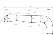
- 2 is a vertical cross-sectional view of an example of a folded portion 210 at the top end of an outer can 20 folded inward.
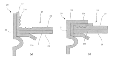
- FIG. 5A and 5B are partial enlarged views showing the configuration of the sealing member for the power storage device according to the present embodiment, in which FIG. 5A shows the configuration before bending and FIG. 5B shows the configuration after bending.
- 5A and 5B are partially enlarged views showing the configuration of a sealing member for an energy storage device according to another embodiment of the present invention, in which FIG. 5A shows the sealing member before bending and FIG. 5B shows the sealing member after bending.
- 10A and 10B are partial enlarged views showing the configuration of a sealing member for an energy storage device according to still another embodiment of the present invention, in which FIG. 10A shows the sealing member before bending and FIG.
- “Overall Configuration” 1 is a cross-sectional view of a battery 1, which is an example of a power storage device according to an embodiment. Note that the power storage device also includes a capacitor.
- the battery 1 includes an electrode body 10 and an exterior can 20 that houses the electrode body 10.
- the exterior can 20 includes a cylindrical portion 21 and a bottom portion 22 that closes one end of the cylindrical portion 21. An opening is formed at the other end of the cylindrical portion 21, and the opening is closed with a sealing member 24.
- the exterior can 20 also houses an electrolyte solution together with the electrode body 10.
- the electrolyte solution may be an aqueous electrolyte solution, but in this embodiment, a non-aqueous electrolyte solution is used.
- a solid electrolyte may be used instead of the electrolyte solution.
- the solid electrolyte for example, a solid or gel-like polymer electrolyte, an inorganic solid electrolyte, or the like is used.
- an annular groove 23 that protrudes radially inward of the battery (or outer can) is provided on the opening side of the tube portion 21.
- a sealing member 24 is supported by the groove 23 and closes the opening of the outer can 20.
- the sealing member 24 side of the battery 1 is referred to as the top
- the bottom 22 side of the outer can 20 is referred to as the bottom.
- the outer can used in the energy storage device of the present disclosure has openings at both ends in the height direction, and each of the pair of openings may be sealed with a sealing member.
- the battery 1 further has a number of electrode leads that extend from various points of the electrode body 10 toward the sealing member 24 and directly connect the first electrode constituting the electrode body 10 to the current collector 26 of the sealing member 24.
- an upper insulating plate 34 is disposed between the electrode body 10 and the sealing member 24.
- the electrode body 10 is a wound type electrode body in which a first electrode and a second electrode are wound with a separator interposed therebetween, and in this embodiment, the first electrode is a positive electrode and the second electrode is a negative electrode, and the electrode lead is a positive electrode lead 19.
- multiple positive electrode leads 19 are arranged at predetermined intervals in the longitudinal direction of the positive electrode, and extend upward from the top of the positive electrode.
- the positive electrode lead 19 electrically connects the positive electrode to the metal parts of the sealing member 24.
- the negative electrode is electrically connected to the outer can 20, for example, by contacting the protruding portion of its core with the outer can 20 via the negative electrode current collector plate. Therefore, the sealing member 24 functions as the positive electrode terminal, and the outer can 20 functions as the negative electrode terminal.
- the upper insulating plate 34 prevents the positive electrode and the positive electrode lead 19 from touching the outer can 20, and also prevents the positive electrode lead 19 from touching the negative electrode of the electrode body 10.
- the negative electrode may also be electrically connected to the bottom of the outer can via a lead.
- the electrode body 10 includes a positive electrode 11, a negative electrode 12, and a separator 13 interposed between the positive electrode 11 and the negative electrode 12. All of these are long strips that are wound in a spiral shape and are alternately stacked in the radial direction of the electrode body 10.
- the positive electrode 11 and the negative electrode 12 each have a mixture layer on their surface.
- the mixture layer of the negative electrode 12 is formed to be one size larger than the mixture layer of the positive electrode 11 in order to prevent lithium precipitation. That is, the mixture layer of the negative electrode 12 is formed longer in the longitudinal direction and width direction (short direction) than the mixture layer of the positive electrode 11.
- the inner starting end of the positive electrode 11 is located outside the starting end of the negative electrode 12, and only the negative electrode 12 and the separator 13 are wound in the center of the electrode body 10.
- the separator 13 is formed with dimensions at least one size larger than the positive electrode 11, and two sheets are arranged to sandwich the positive electrode 11. As a result, when wound, the separator 13 is interposed between the positive electrode 11 and the negative electrode 12.
- the positive electrode 11 has a strip-shaped positive electrode core and a positive electrode composite layer formed on at least one surface of the core.
- the positive electrode core can be a foil of a metal that is stable in the potential range of the positive electrode, such as aluminum or an aluminum alloy, or a film with the metal disposed on the surface.
- the positive electrode composite layer contains a positive electrode active material, a conductive agent such as acetylene black, and a binder such as polyvinylidene fluoride, and is preferably formed on both sides of the positive electrode core.
- a lithium transition metal composite oxide is used as the positive electrode active material.
- the positive electrode lead 19 is connected to the positive electrode, but is preferably directly joined to the positive electrode core by welding or the like.
- the negative electrode 12 has a strip-shaped negative electrode core and a negative electrode composite layer formed on at least one surface of the core.
- the negative electrode core can be made of a foil of a metal that is stable in the potential range of the negative electrode, such as copper or a copper alloy, or a film with the metal disposed on the surface.
- the negative electrode composite layer contains a negative electrode active material and a binder such as styrene-butadiene rubber (SBR), and is preferably formed on both sides of the negative electrode core.
- SBR styrene-butadiene rubber
- graphite or a silicon-containing compound is used as the negative electrode active material.
- a tongue-shaped negative electrode lead may be directly joined to the negative electrode core by welding or the like, and then joined to the current collector plate.
- the non-aqueous electrolyte contained in the exterior can 20 includes a non-aqueous solvent and an electrolyte salt dissolved in the non-aqueous solvent.
- the non-aqueous solvent include esters, ethers, nitriles, amides, and mixed solvents of two or more of these.
- the non-aqueous solvent may contain a halogen-substituted product in which at least a portion of the hydrogen in these solvents is replaced with a halogen atom such as fluorine.
- non-aqueous solvents include ethylene carbonate (EC), ethyl methyl carbonate (EMC), dimethyl carbonate (DMC), and mixed solvents of these.
- a lithium salt such as LiPF6 is used as the electrolyte salt.
- the outer can 20 is a cylindrical metal container with a bottom and an open upper end in the axial direction, and has a cylindrical tube portion 21 and a circular bottom portion 22 when viewed from the bottom.
- the outer can 20 is generally made of a metal whose main component is iron, but may be made of a metal whose main component is aluminum or the like, particularly when the outer can 20 is electrically connected to the positive electrode.
- the outer can 20 also has a groove portion 23 formed along the circumferential direction of the tube portion 21.
- the groove portion 23 is formed in the vicinity of the opening of the outer can 20, at a position spaced a predetermined length downward from the edge of the opening (the upper end of the outer can 20).
- the predetermined length is, for example, a length equivalent to 1 to 20% of the axial length of the outer can 20.
- the bottom 22 of the exterior can 20 is provided with a safety valve mechanism that is activated when an abnormality occurs in the battery 1.
- the bottom 22 is formed with, for example, a thin-walled portion. When an abnormality occurs in the battery 1 and the internal pressure rises, this thin-walled portion breaks preferentially, and a gas exhaust port is formed in the bottom 22.
- the groove portion 23 is a portion of the tubular portion 21 that protrudes inwardly from the exterior can 20, and is formed, for example, by spinning the tubular portion 21 from the outside. At the position where the groove portion 23 is formed, the exterior can 20 is reduced in diameter, and a thin groove is formed on the outer circumferential surface of the tubular portion 21.
- the groove portion 23 preferably has a substantially U-shaped cross section and is formed in a ring shape over the entire circumferential length of the tubular portion 21.
- the groove portion 23 may be formed by processing the tubular portion 21 after the electrode body 10 is placed inside the exterior can 20.
- the inner diameter of the outer can 20 at the position where the groove 23 is formed is, for example, 80 to 99% of the maximum inner diameter of the outer can 20.
- An example of the length of the groove 23 along the radial direction of the outer can 20 is 0.5 to 2.0 mm. Since the diameter of the electrode body 10 is approximately the same as the maximum inner diameter of the outer can 20, the electrode body 10 and the groove 23 overlap in the vertical direction of the battery 1.
- the lower end of the positive electrode lead 19 is connected to the upper end of the positive electrode at multiple points, and the other end is connected to the cap 25 via the current collector 26.
- the sealing member 24 includes, for example, a cap 25, a current collector plate 26, and an electrically insulating gasket 33, and is formed in a disk shape as a whole.
- the sealing member 24 is placed on the groove 23 of the outer can 20 and is fixed to the opening of the outer can 20.
- the upper end of the opening is bent inward and crimped to the sealing member 24 via the gasket 33 to form a bent portion.
- the sealing member 24 is fixed to the upper end of the outer can 20 by the groove 23 and the bent portion of the outer can 20, and closes the opening of the outer can 20.
- the bent portion is formed in a ring shape along the circumferential direction of the outer can 20, and holds the sealing member 24 together with the groove 23.
- the sealing member 24 includes a member for covering the upper opening of the outer can 20, such as an upper insulating plate 34.
- the sealing member 24 may also include a metal rupture plate or the like.
- the cap 25 is a disk-shaped metal member that is exposed to the outside of the exterior can 20 and forms the top surface of the battery 1.
- the cap 25 has a shape (raised portion) in which the radial center part protrudes outward from the battery 1.
- Wiring material is connected to the cap 25 when the battery 1 is modularized to form a battery pack. For this reason, the cap 25 functions as an external terminal of the battery 1, and is also called an external terminal or top cover.
- the positive electrode lead 19 is connected to the current collector 26, and the cap 25 functions as a positive electrode external terminal.
- the current collector 26 is a metal member having a diameter similar to that of the cap 25, and is disposed closer to the electrode body 10 than the cap 25.
- the current collector 26 has an opening 26a in the radial center and is formed in a ring shape.
- the cap 25 and the current collector 26 are welded, and the current collector 26 is welded, for example, to a position closer to the outer periphery than the radial center of the cap 25.
- the current collector 26 has a ring-shaped protrusion 26b, which will be described later, and the protrusion 26b becomes the welded part with the cap 25.
- the positive electrode lead 19 connected to the positive electrode of the electrode body 10 is connected to the current collector 26, so that the current collector 26 functions as a positive electrode current collector. It is also possible to directly join the positive electrode lead to the cap without providing a positive electrode current collector.
- the gasket 33 is provided so as to encase the outer periphery of the laminate of the cap 25 and the current collector plate 26.
- the gasket 33 is an annular resin or rubber member that prevents contact between the cap 25 and the current collector plate 26 and the outer can 20, and ensures electrical insulation between the outer can 20 and the sealing member 24.
- the gasket 33 covers the upper surface of the cap 25, the sides of the cap 25 and the current collector plate 26, and the lower surface of the current collector plate 26 on the outer periphery of the laminate.
- the gasket 33 also seals the inside of the battery 1 by filling the gap between the outer can 20 and the sealing member 24.
- the gasket 33 is formed to cover most of the lower surface of the current collector 26, and is interposed between the current collector 26 and the upper insulating plate 34.
- An opening 33a is formed in the radial center of the gasket 33, which overlaps with the opening 26a of the current collector 26 in the vertical direction.
- the gasket 33 may have a through hole 33b formed in a portion located below the current collector 26. It is expected that electrolyte will accumulate on the upper surface of the gasket 33, and by providing the through hole 33b, such electrolyte can be efficiently returned to the electrode body 10 side.
- multiple through holes 33b are formed along the circumferential direction of the gasket 33.
- the gasket 33 has an inner extension portion 33c that extends inward from the outer periphery of the cap 25.
- the upper end of the exterior can 20 is bent inward to form a bent portion 210.
- This bent portion 210 can be used as a negative electrode external terminal.
- Configuration of bending portion 210" 3 is a vertical (radial) cross-sectional view of an example of a bent portion 210 formed by bending the upper end of the exterior can 20 inward.
- the bent portion 210 is formed by bending the upper end portion inward from a portion 211 extending in the axial direction (vertical direction) of the cylindrical portion 21.
- the bent portion 210 is formed by crimping as described below.
- the bent portion 210 includes a bent portion 212 that bends inward, an intermediate portion 213 that extends inward from the bent portion 212, and a tip portion 214 that is the inner tip.
- the tip portion 214 may be formed thicker than the thin portion located outside the tip portion 214 in the radial direction of the outer can 20.
- the tip portion 214 may protrude toward the closure member from the thin portion in the height direction of the outer can.
- the bent portion 212 and the tip portion 214 may also be thick portions.
- the intermediate portion 213 has a thin portion 213-2 on the side closer to the tip portion 214, a thick portion 213-1 near the center of the intermediate portion 213, and a thin portion 213-3 on the side closer to the bent portion 212.
- the tip of the bent portion 210 extends further inward on the sealing member 24 side, forming an annular tapered slope. This shape makes the tip thicker and easier to hold down (bite into) the inward extending portion 33c of the gasket 33.
- the bent portion 210 has a thick tip portion 214 and a thin portion 213-2 near the inside thereof.
- the pressing force against the gasket below it can be increased.
- This increased pressing force increases the reaction force of the inner extension portion 33c of the gasket 33, and a reliable seal is obtained near the tip portion 214 of the inner extension portion 33c of the gasket 33.
- the thin portion 213-2 is formed on the radial outside of the tip portion 214, the material pressed by the tip portion 214 can be received to maintain the reaction force of the gasket 33.
- the bent portion 210 has an inclined surface on the surface facing the gasket 33 in the radially inner region of the thin portion 213 that approaches the gasket in the radially inner direction, and this region may become thicker as it moves inward.
- the bent portion 210 may satisfy the requirement W5 ⁇ W6.
- the bent portion 210 may also satisfy the requirement W5 ⁇ W4, W3 ⁇ W4, W3 ⁇ W2, or W1 ⁇ W2. If the tip portion 214 has a tapered slope and the thickness in the diagonal direction is W7, the tip portion may satisfy the requirement W6 ⁇ W7.
- the bent portion 210 may also satisfy the requirement W2>W4.
- the tip portion 212 is located on the 0.5A-A side.
- the area of 0.9A-A is the tip portion.
- the thickness of the tip portion W6 or W7 may be increased by 120% or more relative to the minimum thickness W5 in the middle portion of the outer can 20, particularly in the range of 0.5A-0.9A from the outer diameter.
- the bent portion 212 is thicker than the surrounding area. By making the bent portion 212 thicker, the mechanical strength of the bent portion 212 can be improved.
- the bent portion 210 has a thickness that varies in the radial direction, which can be achieved by a crimping device.
- a motor is attached to the crimping device, and its rotating shaft extends in the vertical direction.
- a body is attached to the lower end of the rotating shaft, and the body rotates within a horizontal plane.
- wheels are rotatably supported on a horizontally extending shaft.
- the stand can move up and down, and the crimping device moves up and down as a whole.
- the shaft may extend in a direction other than horizontal.
- This crimping device is positioned above the outer can 20, and the motor is rotated to rotate the body.
- the wheels When the crimping device is moved downward in this state, the wheels come into contact with the upper end of the periphery of the outer can 20.
- the wheels which function as a crimping die, are rotatable, and move while passively rotating above the upper end of the outer can 20. Then, when the crimping device is further lowered in this state, the upper end of the tubular portion 21 is gradually bent inward.
- a notch is formed in the outer peripheral surface of the wheel, which is the surface that contacts the cylindrical portion.
- the inner surface of the notch is in line contact with the cylindrical portion.
- the inner surface of the notch has a first surface that faces the upper end of the cylindrical portion 21 in the height direction of the outer can, a second surface that is opposite the outer peripheral surface of the cylindrical portion in the radial direction, and a curved R portion at a corner where one end of the first surface and one end of the second surface are connected.
- the tip of the bent portion 210 is thickened.
- the R portion that contacts the tip is represented by an arc of a circle with a radius of 3 mm or less in a cross section obtained by cutting the wheel in the radial direction. Furthermore, it may be an arc of a circle with a radius of 2.5 mm or less, and may be an arc of a circle with a radius of 2.0 mm or less.
- the thick portion 213-1 in the middle of the bent portion is thickened.
- FIG. 4 is a partially enlarged view showing the configuration of the sealing member of the energy storage device according to this embodiment, where (a) shows the state before bending and (b) shows the state after bending.
- the resin gasket 33 of the sealing member 24 has a protrusion 33d in the middle, slightly before the upper tip.
- the cap 25, which is the metal sealing body of the sealing member 24, has a recess 25a formed in its peripheral portion at a position that corresponds to the protrusion 33d when the gasket 33 is folded to form the inner extension 33c.
- the sealing body is defined as a member that is placed in the opening of the exterior body and covers at least a portion of the opening. Therefore, the protrusion of the gasket may be fitted into a member other than the cap.
- the convex portion 33d of the gasket 33 fits into the concave portion 25a of the cap 25.
- the reaction force of the gasket 33 acts on the underside of the bent portion 210, reliably sealing this portion.
- the convex portion 33d has a cross-sectional shape that tapers downward, and the concave portion has a corresponding cross-sectional shape. This shape makes it easier for the convex portion 33d of the gasket 33 to fit into the concave portion 25a when folded.
- this cross-sectional shape is not necessarily required, and rectangular parallelepiped convex portion 33d and concave portion 25a may also be used.
- convex portion 33d and concave portion 25a into a circular ring shape, sufficient stress can be obtained in the gasket 33 in the entire radial direction.
- they instead of being circular, they may be divided into multiple parts in the circumferential direction as long as they can be aligned in the circumferential direction.
- FIG. 5 is a partially enlarged view showing the configuration of a sealing member for an energy storage device according to another embodiment, where (a) shows the state before bending and (b) shows the state after bending.
- the shapes of the convex portion 33d and the concave portion 25a are different from those in the example of FIG. 2.
- the convex portion 33d has a shape that increases in thickness toward the tip side of the gasket 33 (the radially inner side of the bent portion 210).
- the radial cross section has a right-angled triangular shape that becomes thicker toward the inside.
- the concave portion 25a has a shape that corresponds to the convex portion 33d.
- the flow of material toward the inside of the gasket can be suppressed, achieving an optimal seal.
- FIG. 6 is a partially enlarged view showing the configuration of a sealing member for a power storage device according to yet another embodiment, where (a) shows the state before bending and (b) shows the state after bending.
- the cross section of the recess formed on the surface of the protrusion 33d facing the metal member is composed of multiple semicircles. Multiple hemispheres may protrude, or a circular protrusion may be formed.
- the bottom surface of the recess 25a may be a hemispherical or semicircular groove that fits the protrusion 33d.
- the recess 25a may also be a circular groove with a flat bottom surface as in FIG. 2, in which case, when the gasket is pressed downward by the bent portion 210, the bottom surface of the protrusion 33d expands to fit the shape of the recess 25a.
- the flow of material toward the inside of the gasket 33 can be suppressed, and suitable sealing can be achieved.
- the gasket 33 When the gasket 33 is folded together with the folding portion 210, the gasket 33 may be folded while being pressed radially inward by the wheel of the crimping device via the folding portion 210.
- the inner extension portion 33c is formed by this pressing, the dimension from the outer periphery of the sealing body may be longer than before the folding starts due to elastic deformation.
- the recess 25a may be formed at a position separated from the outer periphery of the cap by a predetermined distance inward, and the protrusion 33d of the gasket 33 may be fitted into the recess 25a in a state in which the gasket 33 is stretched radially inward.
- the sealing property of the interface between the recess 25a and the protrusion 33d is improved by the reaction force of the protrusion 33d acting radially outward.
- the above reaction force is particularly easy to obtain if the distance between the protrusion 33d and the outer periphery of the cap before folding the gasket 33 (in the protruding direction of the gasket) is shorter than the distance (radial direction) from the outer periphery of the cap to the recess 25a.
- the distance between the convex portion 33d and the outer circumferential edge of the cap before the gasket 33 is folded may be shorter when the gasket 33 is not fitted in the concave portion 25a than when the gasket 33 is fitted in the concave portion 25a.
- the protrusion 33d on the gasket 33 fits into the recess 25a on the sealing body (cap 25) of the sealing member 24, sealing the opening. This prevents the material of the gasket 33 from flowing and escaping inward, and the reaction force of the gasket 33 is sufficient to ensure a reliable seal.
- REFERENCE SIGNS LIST 1 battery 10 electrode body, 11 positive electrode, 12 negative electrode, 13 separator, 19 positive electrode lead, 20 outer can, 21 cylindrical portion, 22 bottom portion, 23 groove portion, 24 sealing material, 25 cap, 25a recessed portion, 26 current collecting plate, 26a opening portion, 26b protruding portion, 33 gasket, 33d protruding portion, 34 upper insulating plate, 210 folded portion, 211 portion, 212 bent portion, 213 intermediate portion, 213-1 thick portion, 213-2: thin portion, 213-3: thin portion, 214 tip portion.
Landscapes
- Chemical & Material Sciences (AREA)
- Chemical Kinetics & Catalysis (AREA)
- Electrochemistry (AREA)
- General Chemical & Material Sciences (AREA)
- Inorganic Chemistry (AREA)
- Sealing Battery Cases Or Jackets (AREA)
- Electric Double-Layer Capacitors Or The Like (AREA)
Priority Applications (3)
| Application Number | Priority Date | Filing Date | Title |
|---|---|---|---|
| JP2025503919A JPWO2024181422A1 (https=) | 2023-02-28 | 2024-02-27 | |
| EP24763901.6A EP4675781A1 (en) | 2023-02-28 | 2024-02-27 | Power storage device |
| CN202480012630.2A CN120693727A (zh) | 2023-02-28 | 2024-02-27 | 蓄电装置 |
Applications Claiming Priority (2)
| Application Number | Priority Date | Filing Date | Title |
|---|---|---|---|
| JP2023030371 | 2023-02-28 | ||
| JP2023-030371 | 2023-02-28 |
Publications (1)
| Publication Number | Publication Date |
|---|---|
| WO2024181422A1 true WO2024181422A1 (ja) | 2024-09-06 |
Family
ID=92589848
Family Applications (1)
| Application Number | Title | Priority Date | Filing Date |
|---|---|---|---|
| PCT/JP2024/007015 Ceased WO2024181422A1 (ja) | 2023-02-28 | 2024-02-27 | 蓄電装置 |
Country Status (4)
| Country | Link |
|---|---|
| EP (1) | EP4675781A1 (https=) |
| JP (1) | JPWO2024181422A1 (https=) |
| CN (1) | CN120693727A (https=) |
| WO (1) | WO2024181422A1 (https=) |
Citations (8)
| Publication number | Priority date | Publication date | Assignee | Title |
|---|---|---|---|---|
| JP2000173565A (ja) | 1998-12-02 | 2000-06-23 | Mitsubishi Cable Ind Ltd | 密閉電池 |
| JP2000353503A (ja) * | 1999-06-10 | 2000-12-19 | Matsushita Electric Ind Co Ltd | 扁平形有機電解液電池及びその製造法 |
| WO2019194055A1 (ja) * | 2018-04-06 | 2019-10-10 | パナソニック株式会社 | 電池 |
| WO2019194238A1 (ja) * | 2018-04-06 | 2019-10-10 | 三洋電機株式会社 | 電池 |
| WO2019194227A1 (ja) * | 2018-04-06 | 2019-10-10 | 三洋電機株式会社 | 電池 |
| WO2020111275A1 (ja) * | 2018-11-30 | 2020-06-04 | パナソニックIpマネジメント株式会社 | 電池 |
| WO2021241215A1 (ja) * | 2020-05-28 | 2021-12-02 | 三洋電機株式会社 | 円筒形電池 |
| WO2022091934A1 (ja) * | 2020-10-28 | 2022-05-05 | 三洋電機株式会社 | 円筒形電池用ガスケット、これを用いた円筒形電池の製造方法及び円筒形電池 |
-
2024
- 2024-02-27 EP EP24763901.6A patent/EP4675781A1/en active Pending
- 2024-02-27 WO PCT/JP2024/007015 patent/WO2024181422A1/ja not_active Ceased
- 2024-02-27 JP JP2025503919A patent/JPWO2024181422A1/ja active Pending
- 2024-02-27 CN CN202480012630.2A patent/CN120693727A/zh active Pending
Patent Citations (8)
| Publication number | Priority date | Publication date | Assignee | Title |
|---|---|---|---|---|
| JP2000173565A (ja) | 1998-12-02 | 2000-06-23 | Mitsubishi Cable Ind Ltd | 密閉電池 |
| JP2000353503A (ja) * | 1999-06-10 | 2000-12-19 | Matsushita Electric Ind Co Ltd | 扁平形有機電解液電池及びその製造法 |
| WO2019194055A1 (ja) * | 2018-04-06 | 2019-10-10 | パナソニック株式会社 | 電池 |
| WO2019194238A1 (ja) * | 2018-04-06 | 2019-10-10 | 三洋電機株式会社 | 電池 |
| WO2019194227A1 (ja) * | 2018-04-06 | 2019-10-10 | 三洋電機株式会社 | 電池 |
| WO2020111275A1 (ja) * | 2018-11-30 | 2020-06-04 | パナソニックIpマネジメント株式会社 | 電池 |
| WO2021241215A1 (ja) * | 2020-05-28 | 2021-12-02 | 三洋電機株式会社 | 円筒形電池 |
| WO2022091934A1 (ja) * | 2020-10-28 | 2022-05-05 | 三洋電機株式会社 | 円筒形電池用ガスケット、これを用いた円筒形電池の製造方法及び円筒形電池 |
Non-Patent Citations (1)
| Title |
|---|
| See also references of EP4675781A1 |
Also Published As
| Publication number | Publication date |
|---|---|
| JPWO2024181422A1 (https=) | 2024-09-06 |
| EP4675781A1 (en) | 2026-01-07 |
| CN120693727A (zh) | 2025-09-23 |
Similar Documents
| Publication | Publication Date | Title |
|---|---|---|
| EP4216345A1 (en) | Secondary battery | |
| JP2021125304A (ja) | 蓄電装置 | |
| JP7656535B2 (ja) | 円筒形電池 | |
| JP7669293B2 (ja) | 密閉電池 | |
| WO2024143319A1 (ja) | 蓄電装置および蓄電モジュール | |
| CN117561645A (zh) | 圆筒形电池 | |
| CN118765462A (zh) | 圆筒形电池 | |
| JP5554086B2 (ja) | 円筒型二次電池 | |
| CN118451601A (zh) | 集电板和蓄电装置 | |
| WO2024181422A1 (ja) | 蓄電装置 | |
| WO2024095902A1 (ja) | 蓄電装置 | |
| WO2024162134A1 (ja) | 蓄電装置 | |
| WO2024181423A1 (ja) | 蓄電装置 | |
| WO2024181468A1 (ja) | 蓄電装置 | |
| WO2024181429A1 (ja) | 蓄電装置 | |
| US12469913B2 (en) | Secondary battery | |
| EP4632884A1 (en) | Cylindrical battery | |
| EP4679615A1 (en) | Cylindrical battery | |
| WO2024181038A1 (ja) | 円筒形電池 | |
| WO2024161920A1 (ja) | 円筒形電池 | |
| WO2024143253A1 (ja) | 円筒形電池 | |
| WO2024161967A1 (ja) | 円筒形電池 | |
| WO2025028548A1 (ja) | 蓄電装置 | |
| WO2025070367A1 (ja) | 円筒形二次電池 | |
| WO2024135555A1 (ja) | 円筒形電池 |
Legal Events
| Date | Code | Title | Description |
|---|---|---|---|
| 121 | Ep: the epo has been informed by wipo that ep was designated in this application |
Ref document number: 24763901 Country of ref document: EP Kind code of ref document: A1 |
|
| ENP | Entry into the national phase |
Ref document number: 2025503919 Country of ref document: JP Kind code of ref document: A |
|
| WWE | Wipo information: entry into national phase |
Ref document number: 2025503919 Country of ref document: JP |
|
| WWE | Wipo information: entry into national phase |
Ref document number: 202517076891 Country of ref document: IN |
|
| WWE | Wipo information: entry into national phase |
Ref document number: 202480012630.2 Country of ref document: CN |
|
| WWP | Wipo information: published in national office |
Ref document number: 202480012630.2 Country of ref document: CN |
|
| WWE | Wipo information: entry into national phase |
Ref document number: 2024763901 Country of ref document: EP |
|
| NENP | Non-entry into the national phase |
Ref country code: DE |
|
| ENP | Entry into the national phase |
Ref document number: 2024763901 Country of ref document: EP Effective date: 20250929 |
|
| ENP | Entry into the national phase |
Ref document number: 2024763901 Country of ref document: EP Effective date: 20250929 |
|
| ENP | Entry into the national phase |
Ref document number: 2024763901 Country of ref document: EP Effective date: 20250929 |
|
| WWP | Wipo information: published in national office |
Ref document number: 202517076891 Country of ref document: IN |
|
| WWP | Wipo information: published in national office |
Ref document number: 2024763901 Country of ref document: EP |