WO2024181156A1 - バルーンカテーテル - Google Patents
バルーンカテーテル Download PDFInfo
- Publication number
- WO2024181156A1 WO2024181156A1 PCT/JP2024/005324 JP2024005324W WO2024181156A1 WO 2024181156 A1 WO2024181156 A1 WO 2024181156A1 JP 2024005324 W JP2024005324 W JP 2024005324W WO 2024181156 A1 WO2024181156 A1 WO 2024181156A1
- Authority
- WO
- WIPO (PCT)
- Prior art keywords
- laser
- balloon catheter
- section
- light
- layer
- Prior art date
- Legal status (The legal status is an assumption and is not a legal conclusion. Google has not performed a legal analysis and makes no representation as to the accuracy of the status listed.)
- Ceased
Links
Images











Classifications
-
- A—HUMAN NECESSITIES
- A61—MEDICAL OR VETERINARY SCIENCE; HYGIENE
- A61B—DIAGNOSIS; SURGERY; IDENTIFICATION
- A61B18/00—Surgical instruments, devices or methods for transferring non-mechanical forms of energy to or from the body
- A61B18/18—Surgical instruments, devices or methods for transferring non-mechanical forms of energy to or from the body by applying electromagnetic radiation, e.g. microwaves
- A61B18/20—Surgical instruments, devices or methods for transferring non-mechanical forms of energy to or from the body by applying electromagnetic radiation, e.g. microwaves using laser
- A61B18/22—Surgical instruments, devices or methods for transferring non-mechanical forms of energy to or from the body by applying electromagnetic radiation, e.g. microwaves using laser the beam being directed along or through a flexible conduit, e.g. an optical fibre; Couplings or hand-pieces therefor
- A61B18/24—Surgical instruments, devices or methods for transferring non-mechanical forms of energy to or from the body by applying electromagnetic radiation, e.g. microwaves using laser the beam being directed along or through a flexible conduit, e.g. an optical fibre; Couplings or hand-pieces therefor with a catheter
- A61B18/245—Surgical instruments, devices or methods for transferring non-mechanical forms of energy to or from the body by applying electromagnetic radiation, e.g. microwaves using laser the beam being directed along or through a flexible conduit, e.g. an optical fibre; Couplings or hand-pieces therefor with a catheter for removing obstructions in blood vessels or calculi
-
- A—HUMAN NECESSITIES
- A61—MEDICAL OR VETERINARY SCIENCE; HYGIENE
- A61B—DIAGNOSIS; SURGERY; IDENTIFICATION
- A61B18/00—Surgical instruments, devices or methods for transferring non-mechanical forms of energy to or from the body
- A61B18/18—Surgical instruments, devices or methods for transferring non-mechanical forms of energy to or from the body by applying electromagnetic radiation, e.g. microwaves
- A61B18/20—Surgical instruments, devices or methods for transferring non-mechanical forms of energy to or from the body by applying electromagnetic radiation, e.g. microwaves using laser
- A61B18/22—Surgical instruments, devices or methods for transferring non-mechanical forms of energy to or from the body by applying electromagnetic radiation, e.g. microwaves using laser the beam being directed along or through a flexible conduit, e.g. an optical fibre; Couplings or hand-pieces therefor
- A61B18/26—Surgical instruments, devices or methods for transferring non-mechanical forms of energy to or from the body by applying electromagnetic radiation, e.g. microwaves using laser the beam being directed along or through a flexible conduit, e.g. an optical fibre; Couplings or hand-pieces therefor for producing a shock wave, e.g. laser lithotripsy
-
- A—HUMAN NECESSITIES
- A61—MEDICAL OR VETERINARY SCIENCE; HYGIENE
- A61M—DEVICES FOR INTRODUCING MEDIA INTO, OR ONTO, THE BODY; DEVICES FOR TRANSDUCING BODY MEDIA OR FOR TAKING MEDIA FROM THE BODY; DEVICES FOR PRODUCING OR ENDING SLEEP OR STUPOR
- A61M25/00—Catheters; Hollow probes
- A61M25/0043—Catheters; Hollow probes characterised by structural features
-
- A—HUMAN NECESSITIES
- A61—MEDICAL OR VETERINARY SCIENCE; HYGIENE
- A61M—DEVICES FOR INTRODUCING MEDIA INTO, OR ONTO, THE BODY; DEVICES FOR TRANSDUCING BODY MEDIA OR FOR TAKING MEDIA FROM THE BODY; DEVICES FOR PRODUCING OR ENDING SLEEP OR STUPOR
- A61M25/00—Catheters; Hollow probes
- A61M25/10—Balloon catheters
-
- A—HUMAN NECESSITIES
- A61—MEDICAL OR VETERINARY SCIENCE; HYGIENE
- A61B—DIAGNOSIS; SURGERY; IDENTIFICATION
- A61B18/00—Surgical instruments, devices or methods for transferring non-mechanical forms of energy to or from the body
- A61B2018/00053—Mechanical features of the instrument of device
- A61B2018/00184—Moving parts
- A61B2018/00202—Moving parts rotating
-
- A—HUMAN NECESSITIES
- A61—MEDICAL OR VETERINARY SCIENCE; HYGIENE
- A61B—DIAGNOSIS; SURGERY; IDENTIFICATION
- A61B18/00—Surgical instruments, devices or methods for transferring non-mechanical forms of energy to or from the body
- A61B2018/00053—Mechanical features of the instrument of device
- A61B2018/00214—Expandable means emitting energy, e.g. by elements carried thereon
- A61B2018/0022—Balloons
-
- A—HUMAN NECESSITIES
- A61—MEDICAL OR VETERINARY SCIENCE; HYGIENE
- A61B—DIAGNOSIS; SURGERY; IDENTIFICATION
- A61B18/00—Surgical instruments, devices or methods for transferring non-mechanical forms of energy to or from the body
- A61B2018/00053—Mechanical features of the instrument of device
- A61B2018/00273—Anchoring means for temporary attachment of a device to tissue
- A61B2018/00279—Anchoring means for temporary attachment of a device to tissue deployable
- A61B2018/00285—Balloons
-
- A—HUMAN NECESSITIES
- A61—MEDICAL OR VETERINARY SCIENCE; HYGIENE
- A61B—DIAGNOSIS; SURGERY; IDENTIFICATION
- A61B18/00—Surgical instruments, devices or methods for transferring non-mechanical forms of energy to or from the body
- A61B2018/00315—Surgical instruments, devices or methods for transferring non-mechanical forms of energy to or from the body for treatment of particular body parts
- A61B2018/00345—Vascular system
-
- A—HUMAN NECESSITIES
- A61—MEDICAL OR VETERINARY SCIENCE; HYGIENE
- A61B—DIAGNOSIS; SURGERY; IDENTIFICATION
- A61B18/00—Surgical instruments, devices or methods for transferring non-mechanical forms of energy to or from the body
- A61B2018/00315—Surgical instruments, devices or methods for transferring non-mechanical forms of energy to or from the body for treatment of particular body parts
- A61B2018/00345—Vascular system
- A61B2018/00404—Blood vessels other than those in or around the heart
-
- A—HUMAN NECESSITIES
- A61—MEDICAL OR VETERINARY SCIENCE; HYGIENE
- A61B—DIAGNOSIS; SURGERY; IDENTIFICATION
- A61B18/00—Surgical instruments, devices or methods for transferring non-mechanical forms of energy to or from the body
- A61B2018/00636—Sensing and controlling the application of energy
- A61B2018/00773—Sensed parameters
- A61B2018/00779—Power or energy
- A61B2018/00785—Reflected power
-
- A—HUMAN NECESSITIES
- A61—MEDICAL OR VETERINARY SCIENCE; HYGIENE
- A61B—DIAGNOSIS; SURGERY; IDENTIFICATION
- A61B18/00—Surgical instruments, devices or methods for transferring non-mechanical forms of energy to or from the body
- A61B18/18—Surgical instruments, devices or methods for transferring non-mechanical forms of energy to or from the body by applying electromagnetic radiation, e.g. microwaves
- A61B18/20—Surgical instruments, devices or methods for transferring non-mechanical forms of energy to or from the body by applying electromagnetic radiation, e.g. microwaves using laser
- A61B2018/208—Surgical instruments, devices or methods for transferring non-mechanical forms of energy to or from the body by applying electromagnetic radiation, e.g. microwaves using laser with multiple treatment beams not sharing a common path, e.g. non-axial or parallel
-
- A—HUMAN NECESSITIES
- A61—MEDICAL OR VETERINARY SCIENCE; HYGIENE
- A61B—DIAGNOSIS; SURGERY; IDENTIFICATION
- A61B18/00—Surgical instruments, devices or methods for transferring non-mechanical forms of energy to or from the body
- A61B18/18—Surgical instruments, devices or methods for transferring non-mechanical forms of energy to or from the body by applying electromagnetic radiation, e.g. microwaves
- A61B18/20—Surgical instruments, devices or methods for transferring non-mechanical forms of energy to or from the body by applying electromagnetic radiation, e.g. microwaves using laser
- A61B18/22—Surgical instruments, devices or methods for transferring non-mechanical forms of energy to or from the body by applying electromagnetic radiation, e.g. microwaves using laser the beam being directed along or through a flexible conduit, e.g. an optical fibre; Couplings or hand-pieces therefor
- A61B2018/2205—Characteristics of fibres
-
- A—HUMAN NECESSITIES
- A61—MEDICAL OR VETERINARY SCIENCE; HYGIENE
- A61B—DIAGNOSIS; SURGERY; IDENTIFICATION
- A61B18/00—Surgical instruments, devices or methods for transferring non-mechanical forms of energy to or from the body
- A61B18/18—Surgical instruments, devices or methods for transferring non-mechanical forms of energy to or from the body by applying electromagnetic radiation, e.g. microwaves
- A61B18/20—Surgical instruments, devices or methods for transferring non-mechanical forms of energy to or from the body by applying electromagnetic radiation, e.g. microwaves using laser
- A61B18/22—Surgical instruments, devices or methods for transferring non-mechanical forms of energy to or from the body by applying electromagnetic radiation, e.g. microwaves using laser the beam being directed along or through a flexible conduit, e.g. an optical fibre; Couplings or hand-pieces therefor
- A61B18/26—Surgical instruments, devices or methods for transferring non-mechanical forms of energy to or from the body by applying electromagnetic radiation, e.g. microwaves using laser the beam being directed along or through a flexible conduit, e.g. an optical fibre; Couplings or hand-pieces therefor for producing a shock wave, e.g. laser lithotripsy
- A61B2018/266—Surgical instruments, devices or methods for transferring non-mechanical forms of energy to or from the body by applying electromagnetic radiation, e.g. microwaves using laser the beam being directed along or through a flexible conduit, e.g. an optical fibre; Couplings or hand-pieces therefor for producing a shock wave, e.g. laser lithotripsy the conversion of laser energy into mechanical shockwaves taking place in a part of the probe
-
- A—HUMAN NECESSITIES
- A61—MEDICAL OR VETERINARY SCIENCE; HYGIENE
- A61B—DIAGNOSIS; SURGERY; IDENTIFICATION
- A61B90/00—Instruments, implements or accessories specially adapted for surgery or diagnosis and not covered by any of the groups A61B1/00 - A61B50/00, e.g. for luxation treatment or for protecting wound edges
- A61B90/39—Markers, e.g. radio-opaque or breast lesions markers
- A61B2090/3966—Radiopaque markers visible in an X-ray image
-
- A—HUMAN NECESSITIES
- A61—MEDICAL OR VETERINARY SCIENCE; HYGIENE
- A61M—DEVICES FOR INTRODUCING MEDIA INTO, OR ONTO, THE BODY; DEVICES FOR TRANSDUCING BODY MEDIA OR FOR TAKING MEDIA FROM THE BODY; DEVICES FOR PRODUCING OR ENDING SLEEP OR STUPOR
- A61M25/00—Catheters; Hollow probes
- A61M25/10—Balloon catheters
- A61M2025/1043—Balloon catheters with special features or adapted for special applications
- A61M2025/1075—Balloon catheters with special features or adapted for special applications having a balloon composed of several layers, e.g. by coating or embedding
-
- A—HUMAN NECESSITIES
- A61—MEDICAL OR VETERINARY SCIENCE; HYGIENE
- A61M—DEVICES FOR INTRODUCING MEDIA INTO, OR ONTO, THE BODY; DEVICES FOR TRANSDUCING BODY MEDIA OR FOR TAKING MEDIA FROM THE BODY; DEVICES FOR PRODUCING OR ENDING SLEEP OR STUPOR
- A61M25/00—Catheters; Hollow probes
- A61M25/10—Balloon catheters
- A61M2025/1043—Balloon catheters with special features or adapted for special applications
- A61M2025/1093—Balloon catheters with special features or adapted for special applications having particular tip characteristics
Definitions
- This disclosure relates to balloon catheters.
- Patent Document 1 discloses this type of probe. Also known is a probe that converts the vaporization expansion force of a liquid obtained by spark discharge in a liquid atmosphere into a mechanical force to perform treatment. Patent Document 2 discloses this type of probe.
- Patent Documents 1 and 2 still have room for improvement in terms of efficiency in ensuring that the force required for treatment is applied to the target site when treating the target site, such as fracturing a calcified area in a blood vessel.
- the present disclosure aims to provide a balloon catheter that can improve efficiency when treating a target area.
- a balloon catheter includes: (1) A long member; an expansion member supported on an outer surface of the elongate member and expandable radially outwardly of the elongate member; From the inside to the outside in the radial direction, a laser emission unit capable of emitting a laser toward the outside in the radial direction; a transmission portion capable of transmitting the laser irradiated from the laser emission portion in the radial direction; a light absorbing section capable of absorbing the laser transmitted through the transmission section,
- the balloon catheter is one in which the laser emission section, the light transmission section and the light absorption section are provided only in the elongated member, only in the expansion member, or separately in both the elongated member and the expansion member.
- a balloon catheter comprises: (2) the elongated member includes the laser emission portion,
- the balloon catheter according to the above (1) is characterized in that the expansion member includes the light-transmitting portion and the light-absorbing portion.
- a balloon catheter comprises: (3) The elongated member is a body member supporting the extension member on an exterior surface thereof; a sleeve member attached to the body member so as to be rotatable relative to the body member in a circumferential direction, The balloon catheter according to (2) above, wherein the sleeve member is provided with the laser emission unit.
- a balloon catheter comprises: (4) The balloon catheter according to (3) above, wherein the sleeve member is attached to the main body member so as to be movable relative to the main body member in the longitudinal direction of the elongated member.
- a balloon catheter comprises: (5) The elongated member is a body member supporting the extension member on an exterior surface thereof; a sleeve member attached to the body member; the sleeve member includes the laser emission portion, The balloon catheter according to the above (2), wherein the laser emission unit is of a full-circumference emission type that emits radial laser.
- a balloon catheter comprises: (6) The balloon catheter according to (5) above, wherein the portion of the sleeve member and/or the main body member interposed between the laser emission unit and the expansion member is configured to be transparent to the laser emitted from the laser emission unit.
- a balloon catheter comprises: (7) The balloon catheter according to (1) above, further comprising a transmission member connected to the laser emission portion for transmitting light, the transmission member having a structure capable of transmitting lasers of different outputs.
- a balloon catheter comprises: (8) The balloon catheter according to (7) above, wherein the transmission member is a double-clad fiber, and the double-clad fiber is capable of propagating a treatment laser as well as a diagnostic laser.
- a balloon catheter comprises: (9) The expansion member is a transmission layer as the transmission portion, capable of transmitting the laser in the radial direction;
- the balloon catheter according to any one of (2) to (4) above, further comprising: a light-absorbing layer as the light-absorbing section, the light-absorbing layer being located radially outward of the transparent layer and absorbing the laser that has passed through the transparent layer.
- a balloon catheter comprises: (10) The balloon catheter according to (1) above, wherein the elongated member comprises the laser emission section, the light transmission section, and the light absorption section.
- a balloon catheter comprises: (11)
- the elongated member is a body member supporting the extension member on an exterior surface thereof; a sleeve member attached to the body member so as to be rotatable relative to the body member in a circumferential direction,
- the balloon catheter according to (10) above, wherein the sleeve member comprises the laser emission section, the light transmission section, and the light absorption section.
- a balloon catheter comprises: (12) The balloon catheter according to (11) above, wherein the sleeve member is attached to the body member so as to be movable relative to the body member in the longitudinal direction of the elongated member.
- a balloon catheter comprises: (13)
- the expansion member is the balloon catheter described in (1) above, which includes the laser emission section, the light transmission section, and the light absorption section.
- a balloon catheter comprises: (14)
- the expansion member is an expansion body portion formed by laminating a plurality of layers; a laser emitter attached to the extended body portion;
- the laser emitter includes the laser emitter,
- the extended body portion is a transmission layer as the transmission portion, capable of transmitting the laser in the radial direction;
- a balloon catheter comprises: (15) The balloon catheter according to any one of (1) to (14) above, wherein the light-transmitting portion and the light-absorbing portion extend over the entire circumferential area of the elongated member.
- a balloon catheter comprises: (16) The balloon catheter according to any one of (1) to (15) above, wherein the laser emission section is arranged at intervals in the circumferential direction of the elongated member.
- the present disclosure provides a balloon catheter that can improve the efficiency of treating a target area.
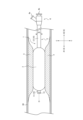
- FIG. 1 is a diagram showing a balloon catheter according to a first embodiment of the present disclosure.
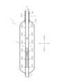
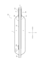
- FIG. 2 is a cross-sectional view of the balloon catheter shown in FIG. 1 taken along a plane parallel to the central axis.
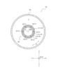
- 2 is a cross-sectional view of the balloon catheter taken along line I-I in FIG. 1 .
- FIG. 2 is a diagram showing a state in which the expansion member of the balloon catheter shown in FIG. 1 is expanded.
- 5 is a cross-sectional view of the balloon catheter shown in FIG. 4 at the same position as in FIG. 2 .
- 5 is a cross-sectional view of the balloon catheter shown in FIG. 4 at the same position as FIG. 3 .
- FIG. 1 is an explanatory diagram for explaining the principle of generation of laser-induced shock waves.
- FIG. 1 is a cross-sectional view of a balloon catheter according to a second embodiment of the present disclosure taken along a plane parallel to the central axis.
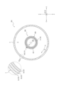
- FIG. 8B is a cross-sectional view of the balloon catheter shown in FIG. 8A taken along a plane perpendicular to the central axis.
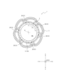
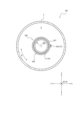
- 11 is a cross-sectional view of a balloon catheter according to a third embodiment of the present disclosure, taken along a plane perpendicular to the central axis.
- FIG. 11 is a cross-sectional view of a balloon catheter according to a fourth embodiment of the present disclosure, taken along a plane parallel to the central axis.
- FIG. 11 is a cross-sectional view of the balloon catheter shown in FIG. 10 taken along a plane perpendicular to the central axis.
- FIG. 11B is a cross-sectional view of the balloon catheter shown in FIG. 10 taken along a plane perpendicular to the central axis, showing a state in which the sleeve member has been rotated relative to the main body member from the state shown in FIG. 11A.
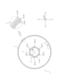
- FIG. 13 is a cross-sectional view of a balloon catheter according to a fifth embodiment of the present disclosure, taken along a plane perpendicular to the central axis.
- FIG. FIG. 11 is a diagram showing a modified example of the balloon catheter as the fourth embodiment shown in FIG. 10.
- FIG. 11 is a diagram showing another modified example of the balloon catheter as the fourth embodiment shown in FIG. 10 .
- FIG. 11 is a diagram showing another modified example of the balloon catheter as the fourth embodiment shown in FIG. 10 .
- FIG. 11 is a diagram showing another modified example of the balloon catheter as the fourth embodiment shown in FIG. 10 .
- 16 is a cross-sectional view of the transmission member shown in FIG. 15 .
- 16 is a diagram showing an example of a procedure performed using the balloon catheter shown in FIG. 15, and shows a state in which treatment of the target site with a treatment laser has been completed from the state shown in FIG. 15.
- FIG. 17 is a diagram showing an example of a procedure performed using the balloon catheter shown in FIG. 15, showing a state in which the sleeve member has been returned from the position shown in FIG. 17 to the position shown in FIG. 15.
- FIG. 17 is a diagram showing an example of a procedure performed using the balloon catheter shown in FIG. 15, and shows a state in which transmission and reception of a diagnostic laser has been completed in order to obtain a diagnostic image of a target area after treatment, from the state shown in FIG. 18.
- Fig. 1 is a diagram showing a balloon catheter 1 as one embodiment of a balloon catheter according to the present disclosure.
- Fig. 1 shows a state in which the balloon catheter 1 is inserted into a blood vessel BV.
- the balloon catheter 1 is a medical instrument that is inserted into the blood vessel BV and is capable of fracturing a calcified region X in the blood vessel BV by utilizing shock waves generated by laser irradiation.
- the calcified region X in the blood vessel BV is exemplified as a target site to be treated by the balloon catheter 1, but the balloon catheter 1 may be used to treat other target sites.
- the balloon catheter 1 of this embodiment comprises a long member 2, an expansion member 3, and a hub 4.
- FIG. 1 shows the balloon catheter 1 percutaneously inserted into a patient's blood vessel BV, and the expansion member 3 introduced to the position of the lesion as the target site where a calcified region X is formed.
- FIG. 1 also shows the expansion member 3 in a contracted state. In the contracted state, the expansion member 3 is guided through the blood vessel BV to the lesion.
- the longitudinal direction of the long member 2 parallel to the central axis O of the long member 2 will be referred to as the "longitudinal direction A.”
- the circumferential direction of the long member 2 around the central axis O of the long member 2 will be referred to as the "circumferential direction B.”
- the radial direction of the long member 2 which is the radial direction of an imaginary circle centered on the central axis O in any cross section perpendicular to the central axis O of the long member 2 will be referred to as the "radial direction C.”
- FIGS. 2 and 3 are cross-sectional views of the balloon catheter 1 shown in FIG. 1.
- FIG. 2 is a cross-sectional view of the balloon catheter 1 taken along a plane that includes the central axis O and is parallel to the central axis O.
- FIG. 2 also shows only the distal end of the balloon catheter 1 (hereinafter referred to as the "distal end").
- FIG. 3 is a cross-sectional view of the balloon catheter 1 taken along line I-I in FIG. 1.
- FIGS. 4 to 6 show the expansion member 3 in the contracted state shown in FIGS. 1 to 3 in an expanded state.
- FIG. 4 shows the expansion member 3 in the contracted state shown in FIG. 1 in an expanded state within the blood vessel BV.
- FIG. 5 is a cross-sectional view at the same position as FIG. 2, showing the expansion member 3 in an expanded state.
- FIG. 6 is a cross-sectional view at the same position as FIG. 3, showing the expansion member 3 in an expanded state.
- the expansion member 3 is supported on the outer surface of the long member 2 and can be expanded outward in the radial direction C of the long member 2.
- the balloon catheter 1 is provided with a laser emission section 31, a transmission section 32, and a light absorption section 33 from the inside to the outside in the radial direction C.
- the laser emission section 31 is configured to be able to emit a laser toward the outside in the radial direction C.
- the transmission section 32 is configured to be able to transmit the laser irradiated from the laser emission section 31 in the radial direction C.
- the light absorption section 33 is capable of absorbing the laser that has transmitted through the transmission section 32.
- the laser emitted from the laser emission section 31 transmits through the transmission section 32 and is absorbed by the light absorption section 33. In the light absorption section 33, plasma is generated by the absorbed laser.
- the plasma generated in the light absorption section 33 is more likely to remain within the light absorption section 33 due to the transmission section 32 that covers the inside of the light absorption section 33 in the radial direction C. This allows a laser-induced shock wave to be sent from the light absorption section 33 toward the outside in the radial direction C. With the balloon catheter 1, the laser-induced shock waves can be applied to the calcified region X in the blood vessel BV, thereby disrupting the calcified region X.
- the balloon catheter 1 it is possible to realize a state in which the expansion member 3 comes into contact with the calcified region X, which is the target site. Therefore, the above-mentioned laser-induced shock waves can be reliably applied to the calcified region X in the blood vessel BV.
- the force required for treating the target site can be secured by utilizing the laser-induced shock waves, and by using the expansion member 3, this laser-induced shock wave can be reliably applied to the target site, thereby improving the efficiency of treating the target site.
- the laser emission unit 31 may be capable of emitting a laser capable of generating laser-induced shock waves in the light absorption unit 33, and may be, for example, a nanosecond pulse laser, a picosecond laser, or a femtosecond pulse laser.
- the transparent portion 32 may be configured to transmit the laser irradiated from the laser emission portion 31, and its configuration is not particularly limited.
- the transparent portion 32 include transparent portions formed of polymeric materials such as polyolefin (e.g., polyethylene, polypropylene, polybutene, ethylene-propylene copolymer, ethylene-vinyl acetate copolymer, ionomer, or a mixture of two or more of these), polyvinyl chloride, polyamide, polyamide elastomer, polyurethane, polyurethane elastomer, polyimide, and fluororesin, or mixtures of these.
- the thickness of the transparent portion 32 can be, for example, 1 to 500 ⁇ m. However, the thickness of the transparent portion 32 is preferably 5 to 100 ⁇ m, and more preferably 10 to 50 ⁇ m.
- the light-absorbing section 33 is not particularly limited in its configuration as long as it is capable of absorbing the laser emitted from the laser-emitting section 31 and transmitted through the transmitting section 32.
- the light-absorbing section 33 may be made of, for example, natural rubber or synthetic rubber such as EPDM, black rubber such as nitrile, chloroprene, or neoprene, or a flexible resin containing a black component such as carbon black or black perylene pigment.
- the thickness of the light-absorbing section 33 may be, for example, 1 to 500 ⁇ m. However, the thickness of the light-absorbing section 33 is preferably 5 to 100 ⁇ m, and more preferably 10 to 50 ⁇ m.
- the above-mentioned laser emission section 31, the transmission section 32 and the light absorption section 33 are provided only in the long member 2, only in the expansion member 3, or separately in both the long member 2 and the expansion member 3.
- the laser emission section 31, the transmission section 32 and the light absorption section 33 are provided separately in both the long member 2 and the expansion member 3.
- a configuration in which the laser emission section 31, the transmission section 32 and the light absorption section 33 are provided only in the long member will be described later (see Figures 8A, 8B, and 12).
- a configuration in which the laser emission section 31, the transmission section 32 and the light absorption section 33 are provided only in the expansion member will also be described later (see Figure 9).
- ⁇ Long member 2> 1 and 4 the long member 2 is percutaneously inserted from its distal end into a patient's blood vessel BV.
- a hub 4 is connected to the proximal end of the long member 2.
- the direction from the proximal end side to the distal end side of the long member 2 in the longitudinal direction A will be simply referred to as the "distal direction A1" or the “distal side”.
- the direction from the distal end side to the proximal end side of the long member 2 in the longitudinal direction A that is, the opposite direction to the distal direction A1
- proximal direction A2 the direction from the distal end side to the proximal end side of the long member 2 in the longitudinal direction A
- proximal direction A2 the direction from the distal end side to the proximal end side of the long member 2 in the longitudinal direction A
- the long member 2 of this embodiment includes a long body member 10 and a laser emitter 20 attached to the body member 10. As shown in Figures 2, 3, 5, and 6, the long member 2 of this embodiment includes a plurality of laser emitters 20 arranged at different positions in the longitudinal direction A and circumferential direction B of the body member 10.
- the main body member 10 supports the expansion member 3. More specifically, the main body member 10 supports the expansion member 3 at its distal end.
- the main body member 10 defines a flow path 10a therein that can supply fluid to the storage space 5 defined by the expansion member 3.
- the fluid supplied to the storage space 5 of the expansion member 3 can be taken out through the flow path 10a by suction or the like.
- the flow path 10a extends from the end of the main body member 10 on the proximal end side that is connected to the hub 4 (hereinafter referred to as the "proximal end") to the position in the longitudinal direction A where the expansion member 3 is provided.
- the proximal end of the flow path 10a is connected to the flow path inside the hub 4. As shown in Figures 2 and 5, the distal end of the flow path 10a is connected to the storage space 5.
- the main body member 10 defines a guidewire insertion hole 10b therein through which a guidewire can be inserted.
- the main body member 10 is guided through the blood vessel BV along the guidewire inserted through the guidewire insertion hole 10b.
- the guidewire insertion hole 10b extends from the proximal end of the main body member 10 to a distal opening defined on the distal end surface of the main body member 10.
- the main body member 10 of this embodiment includes an inner tube 11 that defines a guidewire insertion hole 10b, and an outer tube 12 that covers the outside of the inner tube 11 in the radial direction C and is arranged concentrically with the inner tube 11.
- the inner tube 11 is arranged to protrude further in the distal direction A1 than the distal end of the outer tube 12.
- a marker member 13 is attached to the distal end of the inner tube 11.
- the marker member 13 has X-ray contrast properties.
- the marker member 13 is formed of a material that is highly X-ray opaque.
- the marker member 13 can be made of a material that is highly X-ray opaque, such as platinum, gold, iridium, or tungsten.
- the flow path 10a of this embodiment is defined between the outer surface of the inner tube 11 and the inner surface of the outer tube 12.
- the flow path 10a is connected to the storage space 5 at the distal end of the outer tube 12.
- the configuration of the main body member 10 is not limited to the configuration of this embodiment.
- the main body member 10 of this embodiment is realized by making the flow path 10a and the guide wire insertion hole 10b a double tube structure, but the means for realizing the flow path 10a and the guide wire insertion hole 10b are not limited to the double tube structure.
- the materials that can be used to form the inner tube 11 and outer tube 12 of the main body member 10 include, for example, polyolefins (e.g., polyethylene, polypropylene), polyolefin elastomers (e.g., polyethylene elastomers, polypropylene elastomers, elastomers using ethylene-propylene copolymers, etc.), polyvinyl chloride, ethylene-vinyl acetate copolymers, polyamide elastomers, polyurethanes, thermoplastic resins such as fluororesins, silicone rubber, etc.
- polyolefins e.g., polyethylene, polypropylene
- polyolefin elastomers e.g., polyethylene elastomers, polypropylene elastomers, elastomers using ethylene-propylene copolymers, etc.
- polyvinyl chloride ethylene-vinyl acetate copolymers
- the long member 2 is provided with a laser emission section 31.
- the laser emitter 20 of the long member 2 is provided with a laser emission section 31.
- the laser emitter 20 may be, for example, a nanosecond pulse laser or a femtosecond pulse laser.
- the laser emitter 20 of this embodiment is attached to the main body member 10. More specifically, the laser emitter 20 of this embodiment is attached to the outer surface of the inner tube 11 of the main body member 10 at a position in the longitudinal direction A where the extension member 3 is provided.
- the laser emission section 31 of the laser emitter 20 can emit a laser from the outer surface of the inner tube 11 toward the outside in the radial direction C.
- multiple laser emitters 20 including laser emission units 31 are arranged at intervals in the circumferential direction B of the elongated member 2.
- laser can be emitted from the multiple laser emission units 31 of the multiple laser emitters 20 over a wide range in the circumferential direction B toward the outside in the radial direction C.
- This makes it possible to more reliably apply laser-induced shock waves to the calcified region X not only when the calcified region X is formed over the entire circumferential area of the inner wall of the blood vessel BV, but also when the calcified region X is formed in only a partial circumferential area of the inner wall of the blood vessel BV.
- the irradiation range L1 (see Figure 7) in the circumferential direction B of the light absorption unit 33, to which the laser from each laser emission unit 31 is irradiated, may be set appropriately. Therefore, by appropriately setting the number of laser emitting parts 31 in the circumferential direction B and the irradiation range in the circumferential direction B by each laser emitting part 31 in the light absorbing part 33, it is possible to send laser-induced shock waves toward the outside in the radial direction C within a desired range in the circumferential direction B.
- the laser emitters 20 including the laser emitters 31 are arranged at intervals in the longitudinal direction A of the elongated member 2. In this manner, the laser can be emitted from the laser emitters 31 of the laser emitters 20 over a wide range in the longitudinal direction A toward the outside in the radial direction C. This makes it possible to more reliably apply the laser-induced shock wave to the calcified region X not only when the calcified region X is formed over a wide range in the extension direction of the blood vessel BV, but also when the calcified region X is formed only over a narrow range in the extension direction of the blood vessel BV.
- the laser emitter 20 may be long in the longitudinal direction A and include a laser emitter 31 capable of emitting a wide laser beam with uniform intensity in the radial direction C regardless of the position in the longitudinal direction A. In such a case, the laser emitters 20 do not need to be arranged in a plurality in the longitudinal direction A.
- the laser emitter 20 is equipped with a transmission member 20a including an optical fiber that transmits light to the laser emitter 31.
- the position of the transmission member 20a is not particularly limited, but the transmission member 20a may be disposed along the inner surface of the inner tube 11 of the main body member 10, as shown in Figures 2 and 5.
- the transmission member 20a may also be disposed, for example, along the outer surface of the inner tube 11 or along an insertion hole formed in the peripheral wall of the inner tube 11.
- the transmission member 20a is omitted from illustration in Figures 3 and 6.
- the expansion member 3 is supported on the outer surface of the elongated member 2. Specifically, the expansion member 3 in this embodiment is supported on the outer surface of the main body member 10 of the elongated member 2. More specifically, the expansion member 3 in this embodiment is supported across the outer surface of the inner tube 11 of the main body member 10 and the outer surface of the outer tube 12 of the main body member 10 so as to straddle the distal end of the outer tube 12 in the longitudinal direction A.
- the expansion member 3 in this embodiment is supported on the outer surface of the long member 2 in a state in which it surrounds the outside of the long member 2 in the radial direction C.
- the expansion member 3 surrounds the outside of the outer surface of the long member 2 in the radial direction C over the entire area of the circumferential direction B of the long member 2.
- the expansion member 3 is configured to be expandable outward in the radial direction C of the long member 2. More specifically, the expansion member 3 of this embodiment is configured by an expandable membrane body attached to the outer surface of the main body member 10 of the long member 2. Both ends of the expandable membrane body as the expansion member 3 in the longitudinal direction A are annularly joined to the outer surface of the long member 2 by gluing, fusion, etc., over the entire circumferential direction B of the long member 2. More specifically, the distal end of the expandable membrane body as the expansion member 3 is annularly joined to the outer surface of the inner tube 11 over the entire circumferential direction B.
- the proximal end of the expandable membrane body as the expansion member 3 is annularly joined to the outer surface of the outer tube 12 over the entire circumferential direction B.
- the central portion of the longitudinal direction A of the expandable membrane body as the expansion member 3 is not joined to the outer surfaces of the inner tube 11 and the outer tube 12 over the entire circumferential direction B of the long member 2, and defines an annular storage space 5 between the outer surface of the long member 2 and the central portion of the expandable membrane body as the expansion member 3.
- the expandable membrane body serving as the expansion member 3 is pressed by the fluid and expands outward in the radial direction C of the long member 2 over the entire circumferential direction B of the long member 2.
- the expandable membrane body as the expansion member 3 is in a folded state in a contracted state and wrapped around the outer surface of the long member 2.
- the expandable membrane body as the expansion member 3 in the contracted state expands so that the folds widen and the membrane body protrudes outward in the radial direction C of the long member 2.
- the expandable membrane body as the expansion member 3 assumes an expanded form.
- the fluid supplied to the storage space 5 may be a gas or a liquid, and examples of the fluid include gases such as helium gas, CO2 gas, and O2 gas, and liquids such as saline and contrast medium.
- the expansion member 3 is configured with an expandable membrane body attached to the outer surface of the main body member 10 of the long member 2, but is not limited to this configuration.
- the expansion member 3 may be an annular bag body supported on the outer surface of the main body member 10 of the long member 2.
- the storage space 5 of the expansion member 3 may be a space partitioned only by the bag body as the expansion member 3.
- the expansion member 3 may be configured with an expandable membrane body or a bag body as long as it is capable of forming a balloon that can be expanded and contracted by a fluid.
- the membrane part on the inside in the radial direction C of the bag body constituting the expansion member 3 is interposed between the laser emission part 31 and the membrane part on the outside in the radial direction C of the bag body constituting the expansion member 3. Therefore, it is necessary to configure the membrane part on the inside in the radial direction C of the bag body constituting the expansion member 3 to be capable of transmitting the laser. This allows the laser emitted from the laser emission unit 31 to reach the membrane portion on the outer side of the bag body constituting the expansion member 3 in the radial direction C. Therefore, from the perspective of simplifying the configuration of the expansion member 3, it is preferable that the expansion member 3 be composed of an expandable membrane body as in this embodiment.
- the expansion member 3 of this embodiment includes the above-mentioned transmissive portion 32 and light absorbing portion 33.
- the expansion member 3 of this embodiment includes a first transmissive layer 3a and a second transmissive layer 3b as the transmissive portion 32.
- the expansion member 3 of this embodiment also includes a light absorbing layer 3c as the light absorbing portion 33, which is located outside the first transmissive layer 3a and the second transmissive layer 3b in the radial direction C and absorbs the laser transmitted through the first transmissive layer 3a and the second transmissive layer 3b.
- the first transparent layer 3a and the second transparent layer 3b are laminated in this order from the inside to the outside in the radial direction C.
- the first transparent layer 3a and the second transparent layer 3b may be, for example, transparent resin layers.
- the second transparent layer 3b may be, for example, a base layer of the expandable membrane body that constitutes the expansion member 3.
- the first transparent layer 3a may be, for example, an inner surface layer that constitutes the inner inner surface in the radial direction C of the expandable membrane body that constitutes the expansion member 3.
- the inner surface layer as the first transparent layer 3a may be arranged for the protection, flexibility, etc. of the inner surface of the expandable membrane body.
- Examples of materials for the first transparent layer 3a and the second transparent layer 3b include polyolefins such as polyethylene, polypropylene, and ethylene-propylene copolymers, polyesters such as polyethylene terephthalate, thermoplastic resins such as polyvinyl chloride, ethylene-vinyl acetate copolymers, cross-linked ethylene-vinyl acetate copolymers, and polyurethane, polyamides, etc.
- polyolefins such as polyethylene, polypropylene, and ethylene-propylene copolymers
- polyesters such as polyethylene terephthalate
- thermoplastic resins such as polyvinyl chloride, ethylene-vinyl acetate copolymers, cross-linked ethylene-vinyl acetate copolymers, and polyurethane, polyamides, etc.
- the light absorbing layer 3c may be, for example, a black rubber layer, a black resin layer, etc.
- the light absorbing layer 3c is an outer surface layer that constitutes the outer surface of the expansion membrane body that constitutes the expansion member 3 in the radial direction C.
- the expansion member 3 of this embodiment has a first transmission layer 3a and a second transmission layer 3b as the transmission portion 32, and a light absorption layer 3c as the light absorption portion 33.
- the first transmission layer 3a, the second transmission layer 3b, and the light absorption layer 3c are arranged in the order of the first transmission layer 3a, the second transmission layer 3b, and the light absorption layer 3c from the inside to the outside in the radial direction C.
- the laser emitted from the laser emission portion 31 of the long member 2 described above passes through the fluid contained in the storage space 5 and the first transmission layer 3a and the second transmission layer 3b of the expansion member 3, and is absorbed by the light absorption layer 3c of the expansion member 3.
- the laser-induced shock waves can be directed toward the calcified region X in the blood vessel BV to break up the calcified region X.
- At least one of the first and second transparent layers 3a and 3b serving as the transparent portion 32, and the light absorbing layer 3c serving as the light absorbing portion 33, extend over the entire circumferential direction B of the elongated member 2. In this way, the laser-induced shock waves can be sent from the light absorbing portion 33 outward in the radial direction C over a wider range in the circumferential direction B.
- the expansion member 3 with the light transmitting section 32 and the light absorbing section 33, the laser-induced shock waves sent from the light absorbing section 33 outward in the radial direction C can be made to act on the calcified region X (see FIG. 1, etc.) without attenuation, compared to a configuration in which the light transmitting section 32 and the light absorbing section 33 are provided on a long member. Therefore, from the viewpoint of suppressing attenuation of the laser-induced shock waves, it is preferable that the light transmitting section 32 and the light absorbing section 33 are provided on the expansion member 3.
- the expansion member 3 of this embodiment has a first transparent layer 3a and a second transparent layer 3b as the transparent portion 32, but is not limited to this configuration.
- the expansion member 3 may have a configuration having only one transparent layer as the transparent portion 32.
- the expansion member 3 of this embodiment does not have another layer inside the radial direction C of the first transparent layer 3a and the second transparent layer 3b as the transparent portion 32, but is not limited to this configuration. It may further have another transparent layer that can transmit the laser emitted from the laser emission portion 31.
- the expansion member 3 has only one or more transparent layers inside the radial direction C of the light absorption layer 3c.
- the light absorbing layer 3c as the light absorbing portion 33 is the outer surface layer of the expansion member 3, but another transparent layer may be laminated on the outer side in the radial direction C.
- the light absorbing layer 3c is the outer surface layer of the expansion member 3. In this way, it is possible to suppress attenuation of the laser-induced shock wave due to another transparent layer on the outer side in the radial direction C of the light absorbing layer 3c.
- the long member 2 is connected to the distal side of the hub 4.
- a hub internal flow path communicating with a flow path 10a of the main body member 10 of the long member 2 is defined within the hub 4. Fluid can be supplied from a connection portion 4a provided on the proximal side of the hub 4 through the hub internal flow path to the flow path 10a of the main body member 10 of the long member 2.
- a hub internal insertion hole communicating with a guidewire insertion hole 10b of the main body member 10 of the long member 2 is defined within the hub 4.
- a guidewire can be inserted from a proximal opening 4b, which is the proximal end of the hub internal insertion hole provided on the proximal side of the hub 4, through the hub internal insertion hole into the guidewire insertion hole 10b of the main body member 10 of the long member 2.
- Figure 8A is an enlarged cross-sectional view of the balloon catheter 101 taken on a plane that includes the central axis O and is parallel to the central axis O, showing an enlarged view of the position of the expansion member 103.
- Figure 8B is a cross-sectional view of the balloon catheter 101 taken on a plane perpendicular to the central axis O at the position of the expansion member 103. Both Figures 8A and 8B show the expansion member 103 in an expanded state.
- the long member 102 of this embodiment includes a laser emission section 31, a transmission section 32, and a light absorption section 33. More specifically, the long member 102 of this embodiment includes a main body member 110 and a laser emitter 20. The main body member 110 of the long member 102 includes the laser emission section 31, the transmission section 32, and the light absorption section 33.
- the main body member 110 comprises an inner tube 111 and an outer tube 12.
- the outer tube 12 is not shown in Figures 8A and 8B, its configuration is the same as that of the first embodiment described above (see Figure 2, etc.).
- the inner tube 111 differs from the inner tube 11 of the first embodiment described above (see Figure 3, etc.) in that it comprises a transmitting layer 111b as the transmitting section 32 and a light absorbing layer 111c as the light absorbing section 33, but the other configurations are the same.
- the inner tube 111 defines a guidewire insertion hole 110b inside.
- the inner tube 111 of this embodiment includes a base layer 111a, a transmission layer 111b laminated on the outer side of the base layer 111a in the radial direction C, and a light absorption layer 111c laminated on the outer side of the transmission layer 111b in the radial direction C.
- the base material layer 111a may be made of, for example, the materials listed as examples of the materials used to form the inner tube 11 of the first embodiment described above (see FIG. 3, etc.).
- the transparent layer 111b may be made of, for example, the materials listed as examples of the materials for forming the first transparent layer 3a and the second transparent layer 3b (see FIG. 6) of the expansion member 3 of the first embodiment described above.
- the light absorbing layer 111c may be made of, for example, the materials listed as examples of the materials for forming the light absorbing layer 3c (see FIG. 6) of the extension member 3 of the first embodiment described above.
- the laser emitter 20 is embedded in the peripheral wall of the inner tube 11. More specifically, the laser emitter 20 of this embodiment is sandwiched between the base layer 111a and the transparent layer 111b.
- the laser emitter 31 of the laser emitter 20 can emit a laser from the outer surface of the base layer 111a of the inner tube 111 toward the outside in the radial direction C.
- multiple laser emitters 20 including laser emission units 31 are arranged at intervals in the circumferential direction B of the elongated member 102.
- laser can be emitted from the multiple laser emission units 31 of the multiple laser emitters 20 over a wide range in the circumferential direction B toward the outside in the radial direction C.
- This makes it possible to more reliably apply laser-induced shock waves to the calcified region X not only when the calcified region X is formed over the entire circumferential area of the inner wall of the blood vessel BV, but also when the calcified region X is formed in only a partial circumferential area of the inner wall of the blood vessel BV.
- a plurality of laser emitters 20 including a laser emitter 31 are arranged at intervals in the longitudinal direction A of the elongated member 102.
- the laser can be emitted from the plurality of laser emitters 31 of the plurality of laser emitters 20 in a wide range in the longitudinal direction A toward the outside in the radial direction C.
- This makes it possible to more reliably apply the laser-induced shock wave to the calcified region X not only when the calcified region X is formed in a wide range in the extension direction of the blood vessel BV, but also when the calcified region X is formed only in a narrow range in the extension direction of the blood vessel BV.
- the laser emitter 20 may be long in the longitudinal direction A and may include a laser emitter 31 capable of emitting a wide laser with uniform intensity in the radial direction C regardless of the position in the longitudinal direction A. In such a case, the laser emitters 20 may not be arranged in a plurality in the longitudinal direction A.
- the laser emitter 20 includes a transmission member 20a including an optical fiber that transmits light to the laser emitter 31.
- the position of the transmission member 20a is not particularly limited, but the transmission member 20a may be disposed along the inner surface of the inner tube 111 as shown in FIG. 8A.
- the transmission member 20a may also be disposed, for example, along an insertion hole formed in the peripheral wall of the inner tube 111.
- the transmission member 20a is omitted from the illustration in FIG. 8B.
- the laser emitted from the laser emitter 31 of the laser emitter 20 passes through the transmission layer 111b and is absorbed by the light absorption layer 111c.
- plasma is generated by the laser that has been absorbed.
- the plasma generated in the light absorption layer 111c is likely to remain in the light absorption layer 111c due to the transmission layer 111b that covers the inside of the light absorption layer 111c in the radial direction C. This allows a laser-induced shock wave to be sent from the light absorption layer 111c to the outside in the radial direction C, that is, toward the outside of the long member 102.
- This laser-induced shock wave propagates through the fluid contained in the storage space 5 and the expansion member 103, and is sent to the outside of the expansion member 103 in the radial direction C.
- the laser-induced shock wave can be applied to the calcified region X (see FIG. 1, etc.) in the blood vessel BV (see FIG. 1, etc.) to break up the calcified region X.
- the transmitting portion 32 and the light absorbing portion 33 are provided on the long member 102 located inside the expansion member 103 in the radial direction C. Therefore, the surroundings of the transmitting portion 32 and the light absorbing portion 33 are protected by the expansion member 103. This makes it possible to prevent the transmitting portion 32 and the light absorbing portion 33 from being damaged by the expansion and contraction of the expansion member 103, contact between the expansion member 103 and the inner wall of the blood vessel BV (see FIG. 1, etc.) or the calcified region X (see FIG. 1, etc.), etc. Thus, from the viewpoint of protecting the transmitting portion 32 and the light absorbing portion 33, it is preferable that the transmitting portion 32 and the light absorbing portion 33 are provided on the long member 102.
- the transmitting layer 111b as the transmitting section 32 and the light absorbing layer 111c as the light absorbing section 33 extend over the entire circumferential direction B of the elongated member 102. In this way, the laser-induced shock wave can be sent from the light absorbing section 33 outward in the radial direction C, regardless of the position of the laser emission section 31 in the circumferential direction B.
- the inner tube 111 of this embodiment has a three-layer structure of a base layer 111a, a transmission layer 111b, and a light absorption layer 111c, but is not limited to this structure.
- the inner tube 111 may have a two-layer structure of only the transmission layer 111b and the light absorption layer 111c, for example.
- the laser emitter 20 may be attached to the inner surface of the transmission layer 111b that constitutes the inner surface layer of the inner tube 111.
- the inner tube 111 may also have a structure of four or more layers including the transmission layer 111b and the light absorption layer 111c, for example.
- the inner tube 111 has at least one transmission layer including the transmission layer 111b inside the light absorption layer 111c in the radial direction C, and does not have any layers other than the transmission layer.
- the light absorption layer 111c as the light absorption section 33 is the outer surface layer of the inner tube 111, but another transmission layer may be laminated on the outside of the transmission layer in the radial direction C.
- the light absorption layer 111c is the outer surface layer of the inner tube 111. In this way, it is possible to suppress attenuation of the laser-induced shock wave due to another transparent layer on the outer side of the light absorption layer 111c in the radial direction C.
- the extension member 103 of this embodiment is not particularly limited in its configuration, as long as it is capable of propagating the laser-induced shock waves sent from the light absorption layer 111c of the long member 102 from the inside to the outside in the radial direction C.
- materials for the extension member 103 include polyolefins such as polyethylene, polypropylene, and ethylene-propylene copolymers, polyesters such as polyethylene terephthalate, polyvinyl chloride, ethylene-vinyl acetate copolymers, cross-linked ethylene-vinyl acetate copolymers, thermoplastic resins such as polyurethane, polyamide, polyamide elastomer, silicone rubber, and latex rubber.
- a balloon catheter 201 as another embodiment of the balloon catheter according to the present disclosure will be described with reference to Fig. 9.
- the differences between the balloon catheter 201 and the balloon catheter 1 of the first embodiment (see Fig. 1, etc.) described above will be described, and a description of the common configuration will be omitted.
- FIG. 9 is a cross-sectional view of the balloon catheter 201 taken along a plane perpendicular to the central axis O at the position of the expansion member 203.
- Figure 9 shows the expansion member 203 in an expanded state.
- the long member 202 of this embodiment is composed of a main body member 10.
- the long member 202 of this embodiment differs from the long member 2 of the first embodiment described above (see FIG. 2, etc.) only in the presence or absence of a laser emitter 20.
- the long member 202 of this embodiment does not include a laser emitter 20.
- the expansion member 203 of this embodiment includes a laser emission section 31, a transmission section 32, and a light absorption section 33. More specifically, the expansion member 203 of this embodiment includes an expansion main body section 240 and a laser emission body 241 attached to this expansion main body section 240.
- the expansion body section 240 has the same configuration as the expansion member 3 (see FIG. 6) of the first embodiment described above. That is, the expansion body section 240 is supported on the outer surface of the long member 202, and can be expanded outward in the radial direction C by supplying a fluid to the storage space 5. As shown in FIG. 9, the expansion body section 240 is formed by stacking multiple layers. More specifically, the expansion body section 240 has a first transmission layer 3a and a second transmission layer 3b as the transmission section 32, and a light absorption layer 3c as the light absorption section 33.
- the expansion member 203 is provided with a laser emission section 31. More specifically, in this embodiment, the laser emitter 241 of the expansion member 203 is provided with a laser emission section 31.
- the laser emitter 241 may be, for example, a nanosecond pulse laser or a femtosecond pulse laser.
- the laser emitter 241 is attached to the inner surface of the expansion main body section 240.
- multiple laser emitters 241 are arranged at different positions in the longitudinal direction A and circumferential direction B of the expansion main body section 240.
- the laser emission section 31 of the laser emitter 241 can emit a laser from the inner surface side of the expansion main body section 240 toward the outside in the radial direction C.
- multiple laser emitters 241 including laser emission units 31 are arranged at intervals in the circumferential direction B of the elongated member 202.
- laser can be emitted from the multiple laser emission units 31 of the multiple laser emitters 241 over a wide range in the circumferential direction B toward the outside in the radial direction C.
- This makes it possible to more reliably apply laser-induced shock waves to the calcified region X not only when the calcified region X is formed over the entire circumferential area of the inner wall of the blood vessel BV, but also when the calcified region X is formed in only a partial circumferential area of the inner wall of the blood vessel BV.
- the laser emitters 241 including the laser emission section 31 are arranged at intervals in the longitudinal direction A of the elongated member 202.
- the laser emitter 241 may be long in the longitudinal direction A and include a laser emission section 31 capable of emitting a wide laser with uniform intensity in the radial direction C regardless of the position in the longitudinal direction A. In such a case, the laser emitters 241 do not need to be arranged in multiple in the longitudinal direction A.
- the laser emitter 241 includes a transmission member 241a including an optical fiber that transmits light to the laser emitter 31.
- the position of the transmission member 241a is not particularly limited, but the transmission member 241a may be disposed along the inner surface of the expansion main body 240 as shown in FIG. 9.
- the laser emitted from the laser emission section 31 of the laser emitter 241 passes through the first transmission layer 3a and the second transmission layer 3b of the expansion body section 240 and is absorbed by the light absorption layer 3c.
- plasma is generated by the laser that has been absorbed.
- the plasma generated in the light absorption layer 3c is likely to remain in the light absorption layer 3c due to the first transmission layer 3a and the second transmission layer 3b that cover the inside of the light absorption layer 3c in the radial direction C. This allows a laser-induced shock wave to be sent from the light absorption layer 3c to the outside in the radial direction C, that is, toward the outside of the expansion member 203.
- the laser-induced shock wave can be applied to the calcified region X (see FIG. 1, etc.) in the blood vessel BV (see FIG. 1, etc.) to break up the calcified region X.
- At least one of the first and second transparent layers 3a and 3b as the transparent portion 32, and the light absorbing layer 3c as the light absorbing portion 33, extend over the entire circumferential direction B of the long member 202. In this way, the laser-induced shock wave can be sent from the light absorbing portion 33 outward in the radial direction C, regardless of the position of the laser emission portion 31 in the circumferential direction B.
- a balloon catheter 301 as another embodiment of the balloon catheter according to the present disclosure will be described with reference to Figures 10, 11A, and 11B.
- the balloon catheter 301 of this embodiment is different from the balloon catheter 1 of the first embodiment described above (see Figure 1, etc.) in the configuration of the elongated member 302, but has the other configurations in common.
- the differences between the balloon catheter 301 and the balloon catheter 1 of the first embodiment described above (see Figure 1, etc.) will be described, and a description of the common configuration will be omitted.
- Figure 10 is an enlarged cross-sectional view of the balloon catheter 301 taken along a plane that includes the central axis O and is parallel to the central axis O, showing the position of the expansion member 3.
- Figures 11A and 11B are cross-sectional views of the balloon catheter 301 taken along a plane perpendicular to the central axis O at the position of the expansion member 3.
- Figure 11B shows a state in which the sleeve member 350 of the long member 302 has been rotated in the circumferential direction B relative to the main body member 10 of the long member 302 from the state shown in Figure 11A.
- the elongated member 302 of this embodiment includes a main body member 10 and a sleeve member 350.
- the main body member 10 supports the expansion member 3 on its outer surface.
- the main body member 10 has the same configuration as that of the first embodiment described above, so a description of the main body member 10 will be omitted here.
- the sleeve member 350 is attached to the main body member 10 so as to be rotatable relative to the main body member 10 in the circumferential direction B. More specifically, the sleeve member 350 surrounds the outside of the inner tube 11 of the main body member 10 in the radial direction C and is supported on the outer surface of the inner tube 11.
- the sleeve member 350 of this embodiment includes an annular sleeve body 351 and a laser emitter 352 attached to the annular sleeve body 351.
- the sleeve body 351 is supported on the outer surface of the inner tube 11 so as to be rotatable in the circumferential direction B relative to the inner tube 11.
- the sleeve body 351 extends in the longitudinal direction A between the outer surface of the inner tube 11 and the inner surface of the outer tube 12 at the position where the outer tube 12 is provided.
- the distal end of the sleeve body 351 is located proximal to the position where the expansion member 3 is joined on the outer surface of the inner tube 11. More specifically, the distal end of the sleeve body 351 is located within the accommodation space 5 of the expansion member 3.
- the sleeve body 351 is supported on the outer surface of the inner tube 11 and can rotate in the circumferential direction B relative to the inner tube 11 and the outer tube 12 by sliding against the outer surface of the inner tube 11.
- the sleeve member 350 is provided with a laser emission section 31. More specifically, in this embodiment, the laser emitter 352 of the sleeve member 350 is provided with a laser emission section 31. As shown in Figures 10, 11A, and 11B, the laser emitter 352 of this embodiment is attached to the sleeve body 351. More specifically, the laser emitter 352 of this embodiment is attached on the outer surface of the sleeve body 351. Only one laser emitter 352 of this embodiment is attached on the outer surface of the sleeve body 351.
- the laser emitter 352 may be, for example, a nanosecond pulse laser or a femtosecond pulse laser.
- the laser emission section 31 of the laser emitter 352 can emit a laser from the outer surface of the sleeve body 351 toward the outside in the radial direction C.
- the laser emission unit 31 of this embodiment is provided on the sleeve member 350 that can rotate relatively to the main body member 10. Therefore, by rotating the sleeve member 350 relative to the main body member 10, the position of the laser emission unit 31 in the circumferential direction B can be changed. In other words, a medical professional such as a doctor can operate the sleeve member 350 to operate the emission direction of the laser emitted from the laser emission unit 31. Therefore, in a case where a calcified region X (see FIG. 1, etc.) in a blood vessel BV (see FIG.
- the laser emission unit 31 can be aligned to the position of the calcified region X by operating the sleeve member 350.
- a laser-induced shock wave can be sent locally to the calcified region X.
- the laser emitter 352 includes a transmission member 352a including an optical fiber that transmits light to the laser emitter 31.
- the position of the transmission member 352a is not particularly limited, but the transmission member 352a may be disposed along the outer surface of the sleeve body 351 as shown in FIG. 10.
- the transmission member 352a is omitted from the illustration in FIG. 11A and FIG. 11B.
- a marker member 353 indicating the position of the laser emission part 31 in the circumferential direction B is attached to the distal end of the inner tube 11 of the main body member 10 of the long member 302.
- the marker member 353 has X-ray contrast properties.
- the marker member 353 is formed from a material that is highly X-ray opaque.
- the marker member 353 can be made of a material that is highly X-ray opaque, such as platinum, gold, iridium, or tungsten.
- the sleeve member 350 of this embodiment is configured to be rotatable in the circumferential direction B relative to the main body member 10, and to be movable in the longitudinal direction A relative to the main body member 10. That is, in this embodiment, by rotating the sleeve member 350 in the circumferential direction B relative to the main body member 10, the position of the laser emission unit 31 in the circumferential direction B can be changed, as described above. Furthermore, in this embodiment, by moving the sleeve member 350 in the longitudinal direction A relative to the main body member 10, the position of the laser emission unit 31 in the longitudinal direction A can be changed.
- the position of the laser emission unit 31 can be changed in the longitudinal direction A and the circumferential direction B. Therefore, for example, by moving the sleeve member 350 in the longitudinal direction A relative to the main body member 10 while rotating the sleeve member 350 in the circumferential direction B relative to the main body member 10, even in a configuration in which only one laser emitter 352 is provided, it is possible to send laser-induced shock waves to the entire circumferential area of the inner wall of the blood vessel BV (see FIG. 1, etc.) over a predetermined range in the extension direction of the blood vessel BV. In other words, even in a configuration in which only one laser emitter 352 is provided, it is possible to apply laser-induced shock waves to a wide area of the calcified region X (see FIG. 1, etc.) in the blood vessel BV.
- the operation of the sleeve member 350 described above may be performed manually by a medical professional such as a doctor, or may be performed electrically using a drive device.
- the sleeve member 350 of this embodiment includes only one laser emitter 352, this configuration is not limited.
- the sleeve member 350 may include multiple laser emitters 352, each of which includes a separate laser emitter 31.
- the sleeve member 350 may include multiple laser emitters 352 at different positions in the circumferential direction B, for example.
- the multiple laser emitters 352 may be arranged at equal intervals over the entire area of the circumferential direction B, for example.
- the extension member 3 it is preferable that at least one of the first and second transparent layers 3a and 3b as the transparent portion 32, and the light absorbing layer 3c as the light absorbing portion 33, extend over the entire circumferential direction B of the long member 302. In this way, by rotating the sleeve member 350, the laser-induced shock wave can be sent from the light absorbing portion 33 outward in the radial direction C over the entire circumferential direction B.
- the sleeve member 350 includes a laser emitting portion 31, and the expansion member 3 includes a light transmitting portion 32 and a light absorbing portion 33, but this is not limited to the configuration.
- the sleeve member may also include a laser emitting portion 31, a light transmitting portion 32, and a light absorbing portion 33 (see FIG. 12).
- a balloon catheter 401 as another embodiment of the balloon catheter according to the present disclosure will be described with reference to Fig. 12.
- the balloon catheter 401 of this embodiment is different from the balloon catheter 301 of the above-mentioned fourth embodiment (see Fig. 10, etc.) in the configuration of the elongated member 402 and the expansion member 403.
- the differences between the balloon catheter 401 and the balloon catheter 301 of the above-mentioned fourth embodiment (see Fig. 10, etc.) will be described, and a description of the common configuration will be omitted.
- Figure 12 is a cross-sectional view of the balloon catheter 401 taken along a plane perpendicular to the central axis O at the position of the expansion member 403.
- the balloon catheter 401 comprises a long member 402 and an expansion member 403.
- the expansion member 403 is supported on the outer surface of the long member 402, and can be expanded outward in the radial direction C by supplying fluid to the storage space 5.
- Figure 12 shows the expansion member 403 in an expanded state.
- the expansion member 403 of this embodiment has the same configuration as the expansion member 103 of the second embodiment described above, and therefore will not be described here.
- the long member 402 includes a main body member 10 and a sleeve member 450.
- the main body member 10 has the same configuration as in the fourth embodiment, so a description of it will be omitted here.
- the sleeve member 450 of this embodiment has a laser emission section 31, a transmission section 32, and a light absorption section 33.
- the sleeve member 450 of this embodiment includes a sleeve body 451 and a laser emitter 452.
- the sleeve body 451 of this embodiment includes a base layer 451a, a transmission layer 451b as the transmission section 32 laminated on the outer side of the base layer 451a in the radial direction C, and a light absorption layer 451c as the light absorption section 33 laminated on the outer side of the transmission layer 451b in the radial direction C.
- the base material layer 451a may be made of, for example, the materials listed as examples of the materials used to form the inner tube 11 of the first embodiment described above (see FIG. 3, etc.).
- the transparent layer 451b may be made of, for example, the materials listed as examples of the materials for forming the first transparent layer 3a and the second transparent layer 3b (see FIG. 6) of the expansion member 3 of the first embodiment described above.
- the light absorbing layer 451c may be made of, for example, the materials listed as examples of the materials for forming the light absorbing layer 3c (see FIG. 6) of the extension member 3 of the first embodiment described above.
- the laser emitter 452 of this embodiment is embedded in the peripheral wall of the sleeve body 451. More specifically, the laser emitter 452 of this embodiment is sandwiched between the base layer 451a and the transparent layer 451b.
- the laser emitter 31 of the laser emitter 452 can emit a laser from the outer surface of the base layer 451a of the sleeve body 451 toward the outside in the radial direction C.
- the laser emitter 452 includes a transmission member 452a including an optical fiber that transmits light to the laser emitter 31.
- the position of the transmission member 452a is not particularly limited, but the transmission member 452a may be disposed, for example, along the inner surface of the sleeve body 451 as shown in FIG. 12.
- the laser emitted from the laser emission unit 31 of the laser emitter 452 passes through the transmission layer 451b and is absorbed by the light absorption layer 451c.
- plasma is generated by the laser that has been absorbed.
- the plasma generated in the light absorption layer 451c is likely to stay in the light absorption layer 451c due to the transmission layer 451b that covers the inside of the light absorption layer 451c in the radial direction C. This allows a laser-induced shock wave to be sent from the light absorption layer 451c to the outside in the radial direction C, that is, toward the outside of the sleeve member 450.
- This laser-induced shock wave propagates through the fluid contained in the storage space 5 and the expansion member 403, and is sent to the outside of the expansion member 403 in the radial direction C.
- the laser-induced shock wave can be applied to the calcified region X (see FIG. 1, etc.) in the blood vessel BV (see FIG. 1, etc.) to break up the calcified region X.
- the transmitting layer 451b as the transmitting section 32 and the light absorbing layer 451c as the light absorbing section 33 extend over the entire circumferential direction B of the elongated member 402. In this way, the laser-induced shock wave can be sent from the light absorbing section 33 outward in the radial direction C, regardless of the position of the laser emission section 31 in the circumferential direction B relative to the sleeve body 451.
- the sleeve body 451 of the sleeve member 450 in this embodiment has a three-layer structure of a base layer 451a, a transparent layer 451b, and a light absorbing layer 451c, but is not limited to this structure.
- the sleeve body 451 may have a two-layer structure of only the transparent layer 451b and the light absorbing layer 451c, for example.
- the laser emitter 452 may be attached to the inner surface of the transparent layer 451b that constitutes the inner surface layer of the sleeve body 451.
- the sleeve body 451 may also have a structure of four or more layers including the transparent layer 451b and the light absorbing layer 451c, for example.
- the sleeve body 451 has only at least one transparent layer including the transparent layer 451b inside the light absorbing layer 451c in the radial direction C, and has no layers other than the transparent layer.
- the light absorption layer 451c as the light absorption section 33 is the outer surface layer of the sleeve body 451, but another transparent layer may be laminated on the outer side in the radial direction C.
- the light absorption layer 451c is the outer surface layer of the sleeve body 451. In this way, it is possible to suppress attenuation of the laser-induced shock wave due to another transparent layer on the outer side in the radial direction C of the light absorption layer 451c.
- the balloon catheter according to the present disclosure is not limited to the specific configuration shown in the above-mentioned embodiment, and various modifications, changes, and combinations are possible without departing from the scope of the claims.
- FIG. 13 is a diagram showing a balloon catheter 501 as a modified example of the balloon catheter 301 as the fourth embodiment described above.
- the balloon catheter 501 shown in FIG. 13 differs from the balloon catheter 301 as the fourth embodiment described above in that the laser emitter 552 is configured to emit light all around, and that the sleeve body 551 of the sleeve member 550 of the long member 502 and the inner tube 511 of the body member 510 of the long member 502 are configured to be transparent to the laser emitted from the laser emitter 552, but the other configurations are similar. Therefore, only the above differences will be described here.
- the all-around irradiation type laser emitter 552 may be, for example, a radial fiber.
- the all-around irradiation type laser emitter 552 can emit laser radially in the entire circumferential direction B with the laser emitter 552 as the center.
- the laser emitter 552 is equipped with a transmission member 552a including an optical fiber that transmits light to the laser emitter 31.
- the parts of the sleeve body 551 of the sleeve member 550 and the inner tube 511 of the main body member 510 that are interposed between the laser emitter 552 and the expansion member 3 are configured to be transparent to the laser emitted from the laser emitter 31.
- the radial laser emitted from the laser emission unit 31 of the laser emitter 552 can easily reach the entire area in the circumferential direction B of the expansion member 3.
- a part of both the sleeve member 550 and the main body member 510 is configured to be able to transmit the laser emitted from the laser emission unit 31, but this configuration is not limited to this.
- only one of the sleeve member 550 and the main body member 510 is interposed between the laser emission unit 31 and the expansion member 3, only the intervening one may be configured to be able to transmit the laser emitted from the laser emission unit 31 (see FIG. 14).
- the sleeve body 551 and the inner tube 511 may have any configuration that allows the laser emitted from the laser emission unit 552 to pass through, and there are no particular limitations on their configuration.
- Examples of the sleeve body 551 and the inner tube 511 include transparent configurations made of polymer materials such as polyolefin (e.g., polyethylene, polypropylene, polybutene, ethylene-propylene copolymer, ethylene-vinyl acetate copolymer, ionomer, or a mixture of two or more of these), polyvinyl chloride, polyamide, polyamide elastomer, polyurethane, polyurethane elastomer, polyimide, fluororesin, or other polymer materials, or mixtures of these.
- polyolefin e.g., polyethylene, polypropylene, polybutene, ethylene-propylene copolymer, ethylene-vinyl acetate copolymer, ionomer,
- the sleeve member 550 may be configured not to be rotatable in the circumferential direction B relative to the main body member 510.
- the sleeve member 550 may be configured to be rotatable in the circumferential direction B relative to the main body member 510. Also, in this example, only one all-around irradiation type laser emitter 552 is provided, but this configuration is not limited to this. A plurality of all-around irradiation type laser emitters 552 may be provided at different positions in the circumferential direction B, for example, two of them may be disposed at opposing positions in the radial direction C.
- FIG. 13 shows an example in which the all-around irradiation type laser emitter 552 is attached to the outer surface of the sleeve body 551 on the outside in the radial direction C
- the all-around irradiation type laser emitter 552 may be attached to the distal end of the sleeve body 551 so as to protrude from the distal end of the sleeve body 551 in the distal direction A1.
- it is sufficient that at least the inner tube 511 of the sleeve body 551 and the inner tube 511 is configured to be able to transmit the laser emitted from the laser emitter 552.
- FIG. 15 is a diagram showing a balloon catheter 601 as another modified example of the balloon catheter 301 as the fourth embodiment described above.
- the balloon catheter 601 shown in FIG. 15 differs from the balloon catheter 301 as the fourth embodiment described above in that the transmission member 652a that transmits light to the laser emission section 31 of the laser emitter 352 has a structure capable of transmitting lasers of different outputs, more specifically, the transmission member 652a is a double-clad fiber, but the other configurations are similar. Therefore, only the above differences will be described here.
- Figure 16 is a cross-sectional view of a double-clad fiber as a transmission member 652a.
- Figures 17 to 19 are diagrams showing an example of a procedure using the balloon catheter 601 shown in Figure 15 to consecutively crush the calcified region X (see Figure 1) as a treatment of the target area, and diagnose the target area after the treatment.
- the double clad fiber as the transmission member 652a includes a core 652a1, an inner clad 652a2 that covers the radial outside of the core 652a1, and an outer clad 652a3 that covers the radial outside of the inner clad 652a2.
- the refractive index of the core 652a1 is higher than that of the inner clad 652a2 and higher than that of the outer clad 652a3.
- the refractive index of the inner clad 652a2 is also higher than that of the outer clad 652a3.
- a high-power treatment laser LS1 (see Figure 17) can be propagated in the inner clad 652a2, and a diagnostic laser LS2 (see Figure 19) can be propagated in the core 652a1.
- the laser emission unit 31 can be used to emit the treatment laser LS1, and can also be used to transmit and receive the diagnostic laser LS2 used to obtain diagnostic images of the target area after treatment using OCT (Optical Coherence Tomography) or OFDI (Optical Frequency Domain Imaging).
- FIG. 17 is a diagram showing a state in which the treatment of the target site by the treatment laser LS1 is completed from the state shown in FIG. 15. More specifically, FIG. 17 is a diagram showing a state in which the sleeve member 350 is moved in the proximal direction A2 of the longitudinal direction A relative to the main body member 10 while rotating the sleeve member 350 in the circumferential direction B relative to the main body member 10 from the state shown in FIG. 15.
- the treatment laser LS1 emitted from the laser emission unit 31 can send laser-induced shock waves to the entire circumferential area of the inner wall of the blood vessel BV (see FIG. 1, etc.) over a predetermined range in the extension direction of the blood vessel BV.
- the treatment laser LS1 that is emitted while the sleeve member 350 is moving from the position shown in Figure 15 to the position shown in Figure 17 is shown by a dashed line. This makes it possible to perform the fracturing of the calcified region X (see Figure 1) in the blood vessel BV as a treatment of the target site.
- Figure 18 is a diagram showing the state where the sleeve member 350 has been returned from the position shown in Figure 17 to the position shown in Figure 15. More specifically, Figure 18 is a diagram showing the state where the sleeve member 350 has been moved from the position shown in Figure 17 in the distal direction A1 of the longitudinal direction A relative to the main body member 10 and returned to the same position as in Figure 16. During this movement, the treatment laser LS1 (see Figure 17) and the diagnostic laser LS2 (see Figure 19) are not emitted from the laser emission unit 31. Also, during this movement, the sleeve member 350 is moved in the distal direction A1 without rotating in the circumferential direction B relative to the main body member 10.
- FIG. 19 is a diagram showing a state in which transmission and reception of diagnostic laser LS2 has been completed in order to obtain a diagnostic image of the target site after treatment from the state shown in FIG. 18. More specifically, FIG. 19 is a diagram showing a state in which sleeve member 350 has been moved again in the proximal direction A2 of the longitudinal direction A relative to main body member 10 while rotating sleeve member 350 in the circumferential direction B relative to main body member 10 from the state shown in FIG. 18. During this movement, diagnostic laser LS2 is transmitted and received by laser emission unit 31. In FIG. 19, the diagnostic laser LS2 transmitted and received while sleeve member 350 moves from the position shown in FIG. 18 to the position shown in FIG. 19 is shown by a dashed line. This makes it possible to obtain a diagnostic image of the target site after treatment. In other words, with balloon catheter 601, diagnostic images of the target site after treatment can be obtained without removing balloon catheter 601 from the living body after treatment of the target site.
- This disclosure relates to balloon catheters.
- Balloon catheter 2 Long member 3: Expansion member 3a: First transmission layer (an example of a transmission portion) 3b: Second transmission layer (an example of a transmission portion) 3c: Light absorbing layer (an example of a light absorbing part) 4: Hub 4a: Connection portion 4b: Proximal opening 5: Storage space 10: Main body member 10a: Flow path 10b: Guide wire insertion hole 11: Inner tube 12: Outer tube 13: Marker member 20: Laser emitter 20a: Transmission member 31: Laser emitter 32: Transmitting portion 33: Light absorbing portion 101: Balloon catheter 102: Long member 103: Expansion member 110: Main body member 110b: Guide wire insertion hole 111: Inner tube 111a: Base layer 111b: Transmitting layer (an example of a transmitting portion) 111c: Light absorbing layer (an example of a light absorbing portion) 201: Balloon catheter 202: Long member 203: Expansion member 240: Expansion main body 241: Laser emitting of
Landscapes
- Health & Medical Sciences (AREA)
- Life Sciences & Earth Sciences (AREA)
- Physics & Mathematics (AREA)
- Surgery (AREA)
- Heart & Thoracic Surgery (AREA)
- Public Health (AREA)
- Veterinary Medicine (AREA)
- Engineering & Computer Science (AREA)
- Biomedical Technology (AREA)
- Animal Behavior & Ethology (AREA)
- General Health & Medical Sciences (AREA)
- Optics & Photonics (AREA)
- Otolaryngology (AREA)
- Electromagnetism (AREA)
- Nuclear Medicine, Radiotherapy & Molecular Imaging (AREA)
- Medical Informatics (AREA)
- Molecular Biology (AREA)
- Pulmonology (AREA)
- Biophysics (AREA)
- Hematology (AREA)
- Anesthesiology (AREA)
- Vascular Medicine (AREA)
- Child & Adolescent Psychology (AREA)
- Media Introduction/Drainage Providing Device (AREA)
Priority Applications (4)
| Application Number | Priority Date | Filing Date | Title |
|---|---|---|---|
| CN202480013938.9A CN120751998A (zh) | 2023-02-27 | 2024-02-15 | 球囊导管 |
| EP24763639.2A EP4659695A1 (en) | 2023-02-27 | 2024-02-15 | Balloon catheter |
| JP2025503769A JPWO2024181156A1 (https=) | 2023-02-27 | 2024-02-15 | |
| US19/302,808 US20250380988A1 (en) | 2023-02-27 | 2025-08-18 | Balloon catheter |
Applications Claiming Priority (2)
| Application Number | Priority Date | Filing Date | Title |
|---|---|---|---|
| JP2023-028925 | 2023-02-27 | ||
| JP2023028925 | 2023-02-27 |
Related Child Applications (1)
| Application Number | Title | Priority Date | Filing Date |
|---|---|---|---|
| US19/302,808 Continuation US20250380988A1 (en) | 2023-02-27 | 2025-08-18 | Balloon catheter |
Publications (1)
| Publication Number | Publication Date |
|---|---|
| WO2024181156A1 true WO2024181156A1 (ja) | 2024-09-06 |
Family
ID=92589796
Family Applications (1)
| Application Number | Title | Priority Date | Filing Date |
|---|---|---|---|
| PCT/JP2024/005324 Ceased WO2024181156A1 (ja) | 2023-02-27 | 2024-02-15 | バルーンカテーテル |
Country Status (5)
| Country | Link |
|---|---|
| US (1) | US20250380988A1 (https=) |
| EP (1) | EP4659695A1 (https=) |
| JP (1) | JPWO2024181156A1 (https=) |
| CN (1) | CN120751998A (https=) |
| WO (1) | WO2024181156A1 (https=) |
Cited By (2)
| Publication number | Priority date | Publication date | Assignee | Title |
|---|---|---|---|---|
| WO2025192122A1 (ja) * | 2024-03-14 | 2025-09-18 | テルモ株式会社 | カテーテル及びカテーテルセット |
| WO2026038516A1 (ja) * | 2024-08-13 | 2026-02-19 | テルモ株式会社 | カテーテル |
Citations (6)
| Publication number | Priority date | Publication date | Assignee | Title |
|---|---|---|---|---|
| DE4100290A1 (de) * | 1990-01-17 | 1991-07-18 | Weikl Andreas | Behandlungskatheter |
| JP2014512869A (ja) * | 2011-02-10 | 2014-05-29 | ディーシー ディヴァイシーズ インコーポレイテッド | 心房内圧力軽減開口を形成させ維持する装置および方法 |
| JP2015077168A (ja) * | 2013-10-15 | 2015-04-23 | ニプロ株式会社 | アブレーションデバイス |
| US20200398033A1 (en) * | 2019-06-24 | 2020-12-24 | Boston Scientific Scimed, Inc. | Superheating system for inertial impulse generation to disrupt vascular lesions |
| US20220183738A1 (en) * | 2020-12-11 | 2022-06-16 | Bolt Medical, Inc. | Catheter system for valvuloplasty procedure |
| JP2022537997A (ja) * | 2019-06-19 | 2022-08-31 | ボストン サイエンティフィック サイムド,インコーポレイテッド | 血管石灰の破砕のためのレーザパルスエネルギーの非水系光学ブレークダウンを介したプラズマ生成 |
Family Cites Families (2)
| Publication number | Priority date | Publication date | Assignee | Title |
|---|---|---|---|---|
| JPH05300911A (ja) | 1992-04-28 | 1993-11-16 | Olympus Optical Co Ltd | レーザプローブ |
| US9642673B2 (en) | 2012-06-27 | 2017-05-09 | Shockwave Medical, Inc. | Shock wave balloon catheter with multiple shock wave sources |
-
2024
- 2024-02-15 JP JP2025503769A patent/JPWO2024181156A1/ja active Pending
- 2024-02-15 WO PCT/JP2024/005324 patent/WO2024181156A1/ja not_active Ceased
- 2024-02-15 EP EP24763639.2A patent/EP4659695A1/en active Pending
- 2024-02-15 CN CN202480013938.9A patent/CN120751998A/zh active Pending
-
2025
- 2025-08-18 US US19/302,808 patent/US20250380988A1/en active Pending
Patent Citations (6)
| Publication number | Priority date | Publication date | Assignee | Title |
|---|---|---|---|---|
| DE4100290A1 (de) * | 1990-01-17 | 1991-07-18 | Weikl Andreas | Behandlungskatheter |
| JP2014512869A (ja) * | 2011-02-10 | 2014-05-29 | ディーシー ディヴァイシーズ インコーポレイテッド | 心房内圧力軽減開口を形成させ維持する装置および方法 |
| JP2015077168A (ja) * | 2013-10-15 | 2015-04-23 | ニプロ株式会社 | アブレーションデバイス |
| JP2022537997A (ja) * | 2019-06-19 | 2022-08-31 | ボストン サイエンティフィック サイムド,インコーポレイテッド | 血管石灰の破砕のためのレーザパルスエネルギーの非水系光学ブレークダウンを介したプラズマ生成 |
| US20200398033A1 (en) * | 2019-06-24 | 2020-12-24 | Boston Scientific Scimed, Inc. | Superheating system for inertial impulse generation to disrupt vascular lesions |
| US20220183738A1 (en) * | 2020-12-11 | 2022-06-16 | Bolt Medical, Inc. | Catheter system for valvuloplasty procedure |
Non-Patent Citations (1)
| Title |
|---|
| See also references of EP4659695A1 * |
Cited By (2)
| Publication number | Priority date | Publication date | Assignee | Title |
|---|---|---|---|---|
| WO2025192122A1 (ja) * | 2024-03-14 | 2025-09-18 | テルモ株式会社 | カテーテル及びカテーテルセット |
| WO2026038516A1 (ja) * | 2024-08-13 | 2026-02-19 | テルモ株式会社 | カテーテル |
Also Published As
| Publication number | Publication date |
|---|---|
| CN120751998A (zh) | 2025-10-03 |
| US20250380988A1 (en) | 2025-12-18 |
| JPWO2024181156A1 (https=) | 2024-09-06 |
| EP4659695A1 (en) | 2025-12-10 |
Similar Documents
| Publication | Publication Date | Title |
|---|---|---|
| US20250380988A1 (en) | Balloon catheter | |
| EP4117563B1 (en) | Acoustic performance monitoring system within intravascular lithotripsy device | |
| US11622779B2 (en) | Photoacoustic pressure wave generation for intravascular calcification disruption | |
| JP6968146B2 (ja) | 液体レーザ誘起圧力波を放射するカテーテルシース | |
| AU2001273471B8 (en) | Thermal treatment methods and apparatus with focused energy application | |
| JP2021532929A (ja) | 処置モード選択システム及びこれを含むレーザカテーテルシステム | |
| JP2019521802A5 (https=) | ||
| US20230255635A1 (en) | Manifold integrated handle assembly for intravascular lithotripsy device | |
| JPWO2020071023A1 (ja) | 光照射医療装置 | |
| US12343555B2 (en) | Light irradiation system, catheter, and light irradiation device | |
| CN116784933A (zh) | 一种冲击波球囊导管装置 | |
| US20140207128A1 (en) | Ablation device | |
| CN115135267B (zh) | 用于声学放大激光诱导的压力波的导管护套 | |
| JP7346134B2 (ja) | カテーテル、及び、光照射システム | |
| US20250222270A1 (en) | Phototherapy device | |
| WO2025192122A1 (ja) | カテーテル及びカテーテルセット | |
| WO2026038517A1 (ja) | カテーテルシステム | |
| WO2026038518A1 (ja) | カテーテル | |
| JP2022075134A (ja) | 光照射デバイス、及び、光照射システム | |
| WO2026038514A1 (ja) | カテーテル | |
| WO2026038515A1 (ja) | カテーテル | |
| WO2026038519A1 (ja) | カテーテル | |
| JP2018143539A (ja) | 医療デバイス | |
| WO2026038516A1 (ja) | カテーテル | |
| JPH11276499A (ja) | レーザ照射装置 |
Legal Events
| Date | Code | Title | Description |
|---|---|---|---|
| 121 | Ep: the epo has been informed by wipo that ep was designated in this application |
Ref document number: 24763639 Country of ref document: EP Kind code of ref document: A1 |
|
| WWE | Wipo information: entry into national phase |
Ref document number: 2025503769 Country of ref document: JP |
|
| WWE | Wipo information: entry into national phase |
Ref document number: 202480013938.9 Country of ref document: CN |
|
| WWE | Wipo information: entry into national phase |
Ref document number: 202517080345 Country of ref document: IN |
|
| WWP | Wipo information: published in national office |
Ref document number: 202517080345 Country of ref document: IN |
|
| NENP | Non-entry into the national phase |
Ref country code: DE |
|
| WWP | Wipo information: published in national office |
Ref document number: 202480013938.9 Country of ref document: CN |
|
| WWP | Wipo information: published in national office |
Ref document number: 2024763639 Country of ref document: EP |