WO2024181095A1 - 接眼光学系およびヘッドマウントディスプレイ - Google Patents
接眼光学系およびヘッドマウントディスプレイ Download PDFInfo
- Publication number
- WO2024181095A1 WO2024181095A1 PCT/JP2024/004551 JP2024004551W WO2024181095A1 WO 2024181095 A1 WO2024181095 A1 WO 2024181095A1 JP 2024004551 W JP2024004551 W JP 2024004551W WO 2024181095 A1 WO2024181095 A1 WO 2024181095A1
- Authority
- WO
- WIPO (PCT)
- Prior art keywords
- optical system
- display
- lens group
- lens
- visual optical
- Prior art date
- Legal status (The legal status is an assumption and is not a legal conclusion. Google has not performed a legal analysis and makes no representation as to the accuracy of the status listed.)
- Ceased
Links
Images

















Classifications
-
- G—PHYSICS
- G02—OPTICS
- G02B—OPTICAL ELEMENTS, SYSTEMS OR APPARATUS
- G02B27/00—Optical systems or apparatus not provided for by any of the groups G02B1/00 - G02B26/00, G02B30/00
- G02B27/01—Head-up displays
- G02B27/017—Head mounted
- G02B27/0176—Head mounted characterised by mechanical features
-
- G—PHYSICS
- G02—OPTICS
- G02B—OPTICAL ELEMENTS, SYSTEMS OR APPARATUS
- G02B15/00—Optical objectives with means for varying the magnification
- G02B15/14—Optical objectives with means for varying the magnification by axial movement of one or more lenses or groups of lenses relative to the image plane for continuously varying the equivalent focal length of the objective
- G02B15/142—Optical objectives with means for varying the magnification by axial movement of one or more lenses or groups of lenses relative to the image plane for continuously varying the equivalent focal length of the objective having two groups only
-
- G—PHYSICS
- G02—OPTICS
- G02B—OPTICAL ELEMENTS, SYSTEMS OR APPARATUS
- G02B17/00—Systems with reflecting surfaces, with or without refracting elements
- G02B17/08—Catadioptric systems
-
- G—PHYSICS
- G02—OPTICS
- G02B—OPTICAL ELEMENTS, SYSTEMS OR APPARATUS
- G02B25/00—Eyepieces; Magnifying glasses
-
- G—PHYSICS
- G02—OPTICS
- G02B—OPTICAL ELEMENTS, SYSTEMS OR APPARATUS
- G02B25/00—Eyepieces; Magnifying glasses
- G02B25/001—Eyepieces
-
- G—PHYSICS
- G02—OPTICS
- G02B—OPTICAL ELEMENTS, SYSTEMS OR APPARATUS
- G02B27/00—Optical systems or apparatus not provided for by any of the groups G02B1/00 - G02B26/00, G02B30/00
- G02B27/01—Head-up displays
- G02B27/017—Head mounted
- G02B27/0172—Head mounted characterised by optical features
-
- G—PHYSICS
- G02—OPTICS
- G02B—OPTICAL ELEMENTS, SYSTEMS OR APPARATUS
- G02B27/00—Optical systems or apparatus not provided for by any of the groups G02B1/00 - G02B26/00, G02B30/00
- G02B27/02—Viewing or reading apparatus
-
- G—PHYSICS
- G02—OPTICS
- G02B—OPTICAL ELEMENTS, SYSTEMS OR APPARATUS
- G02B5/00—Optical elements other than lenses
- G02B5/30—Polarising elements
-
- G—PHYSICS
- G02—OPTICS
- G02B—OPTICAL ELEMENTS, SYSTEMS OR APPARATUS
- G02B27/00—Optical systems or apparatus not provided for by any of the groups G02B1/00 - G02B26/00, G02B30/00
- G02B27/01—Head-up displays
- G02B27/0149—Head-up displays characterised by mechanical features
- G02B2027/0154—Head-up displays characterised by mechanical features with movable elements
Definitions
- This disclosure relates to an eyepiece optical system and a head-mounted display equipped with an eyepiece optical system.
- Patent Document 1 discloses an observation optical system for observing an image displayed on an image display surface.
- the observation optical system of Patent Document 1 is used as a head-mounted display that enlarges and displays an original image displayed on an image display element such as a liquid crystal display, for observation.
- Patent Document 2 discloses an observation optical system that makes it possible to observe an optical image of the original image displayed on the display surface from the pupil plane.
- the observation optical system of Patent Document 2 has a diopter adjustment lens group and a subsequent lens group arranged in this order from the pupil plane side to the display surface side.
- the subsequent lens group has at least one positive lens, and thereby shares part of the refractive power of the entire observation optical system.
- the present disclosure provides an eyepiece optical system and a head-mounted display that can make it easier for the user to ensure a clear field of vision.
- the eyepiece optical system of the present disclosure guides light between the user's pupil and the display surface.
- the eyepiece optical system includes a first lens group and a second lens group arranged in order from the user's pupil side to the display side facing the display surface.
- the first lens group includes a first lens element and a second lens element arranged in order from the pupil side to the display side, and has a first partial reflecting surface on the pupil side of the first lens element and a second partial reflecting surface between the first lens element and the second lens element.
- the second lens group includes a third lens element having an aspheric surface convex toward the pupil side.
- the focal length of the first lens group is 5 times or less the difference between the maximum height of the chief ray on the pupil side surface, which is the pupil side of the first lens element in the first lens group, and the maximum image height on the display surface.
- the head-mounted display in this disclosure includes a display element having a display surface for displaying an image, and the above-mentioned eyepiece optical system.
- the eyepiece optical system and head-mounted display disclosed herein make it easier for the user to ensure a clear field of vision.
- FIG. 1 is a diagram illustrating a configuration of a head-mounted display according to a first embodiment of the present disclosure.
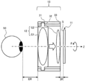
- FIG. 1 is a diagram illustrating a visibility adjustment mechanism in a display device; Lens arrangement diagram showing the configuration of the visual optical system according to the first embodiment
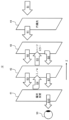
- FIG. 1 is a diagram for explaining the operation of the visual optical system according to the first embodiment; A diagram for explaining parameters in a visual optical system.
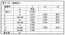
- FIG. 1 is a diagram showing surface data of the visual optical system in the first numerical example.
- FIG. 1 is a table showing aspheric data of a visual optical system in a first numerical example.
- FIG. 1 is a table showing various data of the visual optical system in Numerical Example 1.
- FIG. 1 is an aberration diagram showing various aberrations of the visual optical system in Numerical Example 1.
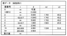
- Lens arrangement diagram showing the configuration of the visual optical system according to Example 2 FIG. 1 is a diagram showing surface data of the visual optical system in the second numerical example.
- FIG. 1 is a table showing aspheric data of a visual optical system in a numerical example 2.
- 1 is a table showing various data of the visual optical system in Numerical Example 2.
- FIG. 1 is an aberration diagram showing various aberrations of the visual optical system in Numerical Example 2.
- FIG. 1 is a diagram showing surface data of the visual optical system in the third numerical example.
- FIG. 1 is a table showing aspheric data of a visual optical system in a numerical example 3.
- 1 is a table showing various data of the visual optical system in Numerical Example 3.
- FIG. 11 is an aberration diagram showing various aberrations of the visual optical system in Numerical Example 3.
- Lens arrangement diagram showing the configuration of the visual optical system according to Example 4 FIG. 1 is a diagram showing surface data of the visual optical system in the fourth numerical example.
- FIG. 1 is a table showing aspheric data of a visual optical system in a numerical example 4.
- 1 is a table showing various data of the visual optical system in Numerical Example 4.
- FIG. 11 is an aberration diagram showing various aberrations of the visual optical system in Numerical Example 4.
- Lens arrangement diagram showing the configuration of the visual optical system according to Example 5 FIG.
- FIG. 1 is a diagram showing surface data of the visual optical system in the fifth numerical example.
- FIG. 1 is a table showing aspheric data of a visual optical system in Numerical Example 5. Table showing various data of the visual optical system in Numerical Example 5
- FIG. 11 is an aberration diagram showing various aberrations of the visual optical system in Numerical Example 5.
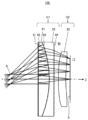
- Lens arrangement diagram showing the configuration of the visual optical system according to Example 6
- FIG. 1 is a diagram showing surface data of the visual optical system in Numerical Example 6.
- FIG. 1 is a table showing aspheric data of the visual optical system in Numerical Example 6.
- FIG. 11 is an aberration diagram showing various aberrations of the visual optical system in Numerical Example 6.
- Head Mounted Display A head mounted display (HMD) according to a first embodiment will be described with reference to FIGS. 1 and 2.
- FIG. 1 is a diagram showing the configuration of an HMD 1 according to a first embodiment of the present disclosure.
- the HMD 1 is a display device that is worn on the head of a user 5 and allows the user 5 to view a virtual image V.
- the HMD 1 is configured in the form of glasses, for example, with two projection units 10 provided as portions corresponding to both eyes of the user 5.
- the HMD 1 includes a display element 11, a visual optical system 12, and a visibility adjustment mechanism 13 for each projection unit 10.
- Each projection unit 10 of the HMD 1 projects display light, which is light for visually recognizing a virtual image V, from the display element 11 to the eye 50 of the user 5 via the visual optical system 12.
- Such an HMD 1 is useful because it has a wide viewing angle corresponding to the range in which the virtual image V is visually recognized by the user 5, and is small and lightweight.
- the HMD 1 further includes fixing members 14 that fix the position of each projection unit 10 relative to, for example, the eyes 50 of the user 5 wearing the HMD 1.
- fixing members 14 include a forehead rest, a nose rest, a frame member, or a fixing band.
- the visual optical system 12 in this embodiment is composed of a polarized reflection optical system that folds the optical path by utilizing reflection according to the polarization of light. This allows the visual optical system 12 to be configured to be thin with a short overall optical length, making it easy to miniaturize the HMD 1.
- the visual optical system 12 in this embodiment has a thin configuration and a configuration that makes it easy to ensure a wide viewing angle in the HMD 1. Details of the visual optical system 12 will be described later.
- the diopter adjustment mechanism 13 is an example of a movable mechanism for adjusting the diopter in the HMD 1 according to the visual acuity of each eye 50.
- the diopter adjustment mechanism 13 allows, for example, the user 5 to adjust the virtual image V in the HMD 1 so that it is easier to view according to his or her own visual acuity.
- Figure 2 shows an example of the diopter adjustment mechanism 13.
- the direction along the optical axis of the visual optical system 12 is referred to as the Z direction, and the direction of rotation around the optical axis is referred to as the ⁇ direction.
- the pupil side of the visual optical system 12 where the pupil of the eye 50 is assumed to be located is referred to as the -Z side, and the display side where the display element 11 is located is referred to as the +Z side.
- the display element 11 has a display surface S that displays various images.
- the display surface S includes, for example, a plurality of pixels, and emits display light that shows an image for visualizing a virtual image V.
- the display element 11 is, for example, configured as a micro OLED (organic light emitting diode) display. Such a display element 11 makes it easy to achieve high-definition image quality for the virtual image V visually recognized by the user 5.
- a visual optical system 12 is provided that can easily ensure a wide viewing angle even if the display surface S of the display element 11 is small.
- the display element 11 is not limited to the above configuration, but may be, for example, a liquid crystal display device, a liquid crystal on silicon (LCOS) device, a digital mirror device (DMD), a micro LED display, or various types of micro displays.
- LCOS liquid crystal on silicon
- DMD digital mirror device
- micro LED display or various types of micro displays.
- the visual optical system 12 has a distance to the eye 50 on the -Z side along the optical axis, i.e., an eye relief ER, and a distance to the display surface S of the display element 11 on the +Z side, i.e., a back focus BF.
- the visual optical system 12 includes a first lens G1 arranged on the -Z side and a second lens group G2 arranged on the +Z side.
- the diopter adjustment mechanism 13 achieves diopter adjustment with a simple configuration in which the first lens group G1 in the visual optical system 12 is moved in the Z direction.
- the diopter adjustment mechanism 13 fixes the second lens group G2 in the visual optical system 12, and adjusts the diopter to correct stronger myopic vision as the first lens group G1 is moved toward the +Z side.
- the diopter adjustment mechanism 13 may be configured so that the first lens group G1 of the visual optical system 12 does not rotate in the ⁇ direction when moving in the Z direction, and is configured, for example, by a cam mechanism.
- the diopter adjustment mechanism 13 includes a cam barrel 31, a lens holder 32, and a rotation restriction unit 33.
- the cam barrel 31 is, for example, a cylindrical member having a spiral cam groove, and is configured to be rotatable in the ⁇ direction.
- the diopter adjustment mechanism 13 may include a member that can be operated by the user 5, and may include, for example, a dial or ring that rotates the cam barrel 31.
- the lens holding portion 32 is a member that holds the first lens group G1 of the visual optical system 12 therein. In the lens holding portion 32, the relative positions between the various lenses in the first lens group G1 of the visual optical system 12 are fixed.
- the lens holding portion 32 is provided with pins and the like that engage with the cam grooves of the cam barrel 31.
- the rotation restriction unit 33 fixes the angular position of the lens holding unit 32 in the ⁇ direction while allowing movement of the lens holding unit 32 in the Z direction.
- the rotation restriction unit 33 is configured, for example, by providing a tube member between the cam tube 31 and the lens holding unit 32, with a hole through which the pin of the lens holding unit 32 passes extending in the Z direction.
- the lens holder 32 moves in the Z direction in response to the rotation of the cam barrel 31, and at this time the rotation of the lens holder 32 is restricted. This makes it possible to suppress degradation of image quality caused by, for example, a shift in the angular position of the first lens group G1 of the visual optical system 12.
- the diopter adjustment mechanism 13 does not need to restrict the rotation of the first lens group G1 of the visual optical system 12, and may be configured, for example, by a screw tightening method.
- the visual optical system 12 and the diopter adjustment mechanism 13 may be provided as an integrated module.
- the eyepiece optical system of this embodiment may include the diopter adjustment mechanism 13 in addition to the visual optical system 12.
- Figure 3 is a lens arrangement diagram showing the configuration of the visual optical system 12 in Example 1 of this embodiment.
- a virtual aperture A corresponding to the pupil of the user 5 of the HMD 1 is illustrated on the -Z side of the visual optical system 12 (hereinafter also referred to as "pupil A").
- Figure 3 also illustrates the light rays of display light Bi from each part of the display surface S of the display element 11, passing through the visual optical system 12 and reaching the pupil A.
- the visual optical system 12 in this embodiment includes a first lens element 21, a second lens element 22, and a third lens element 23, arranged in order from the pupil side (-Z side) to the display side (+Z side) along the Z direction of the optical axis.
- the first lens element 21 and the second lens element 22 form a first lens group G1 that is movable in the Z direction, for example, with their relative positions fixed.
- the third lens element 23 forms a second lens group G2 whose distance from the display surface S is fixed.
- the visual optical system 12 is composed of these two lens groups G1 and G2, and the distance between them can be changed using the diopter adjustment mechanism 13 ( Figure 2) described above.
- Figure 3 shows an example of the arrangement of the visual optical system 12 in a zero diopter state where diopter adjustment has not been performed.
- the position of the first lens group G1 of the visual optical system 12 in the zero diopter state is, for example, on the furthest -Z side within the movable range of the diopter adjustment mechanism 13.
- the first lens group G1 has a power (i.e., refractive power) that ensures a wide viewing angle.
- the second lens group G2 can correct aberrations such as field curvature.
- the first lens element 21 and the second lens element 22 are cemented together.
- the first and second lens elements 21, 22 are each made of a lens material such as glass or resin.
- the first and second lens elements 21, 22 made of a glass material tend to reduce chromatic aberration and the like, making it easier to improve the image quality of the virtual image V.
- the first lens element 21 is a reflective polarizing lens equipped with a polarizing reflecting surface 41.
- the -Z side surface of the first lens element 21 is closest to the pupil in the visual optical system 12, and faces, for example, the eye 50 of the user 5 (see FIG. 2).
- the polarized reflecting surface 41 is provided on the -Z side surface of the first lens element 21.
- the polarized reflecting surface 41 is configured as a polarized reflector by attaching a reflective polarizing film.
- the polarized reflecting surface 41 reflects light of one polarized component (e.g., p-polarized light) of the mutually orthogonal polarized components for linear polarization, for example, and transmits light of the other polarized component (e.g., s-polarized light).
- the polarized reflecting surface 41 on the -Z side of the first lens element 21 is an example of a first partial reflecting surface in this embodiment.
- a quarter-wave plate 42 is provided on the +Z side of the polarizing reflection surface 41.
- the quarter-wave plate 42 is an example of a phase difference element that imparts a phase delay of a quarter wavelength in a preset polarization direction to incident light.
- the quarter-wave plate 42 is constructed by attaching a quarter-wave film to the +Z side of a reflective polarizing film on the -Z side of the first lens element 21.
- the quarter-wave plate 42 and the polarizing reflection surface 41 are arranged so that their orientations in the polarization direction are aligned with each other.
- the phase difference element is not limited to a quarter-wave plate.
- the phase difference element may be any element that imparts a phase difference of a quarter wavelength to the incident light in a preset polarization direction.
- the phase difference element may be composed of two 1/8 wavelength plates, or four 1/16 wavelength plates.
- the phase difference of a quarter wavelength imparted by the phase difference element may be a phase difference of 0.24 ⁇ to 0.26 ⁇ in the electric field oscillation direction of the polarized light.
- the first lens group G1 constitutes a beam splitter lens equipped with a half mirror 43.
- the half mirror 43 is provided on the joint surface between the first and second lens elements 21, 22.
- the half mirror 43 is constituted by applying a visible light reflective coating or vapor deposition, etc., with a reflectance set to a predetermined value, to the +Z side surface of the first lens element 21 or the -Z side surface of the second lens element 22.
- the predetermined value of the reflectance is, for example, 50%.
- the half mirror 43 between the first and second lens elements 21, 22 is an example of a second partially reflective surface that reflects a portion of the incident light and transmits the remainder.
- a circular polarizer 44 is provided on the +Z side surface of the second lens element 22.
- the circular polarizer 44 is arranged so as to set right-handed or left-handed circular polarization for the display light Bi from the display element 11.
- the circular polarizer 44 is configured by attaching a circular polarizing film to the +Z side surface of the second lens element 22.
- the circular polarizer 44 is not limited to the above configuration, and may be provided, for example, on the -Z or +Z side surface of the third lens element 23 of the second lens group G2, or may be provided between the visual optical system 12 and the display element 11 (for example, the display surface of the display element 11).
- the first lens element 21 is, for example, a spherical lens, and has positive power.
- the -Z side of the first lens element 21 is, for example, a flat surface. This makes it easier to provide the polarizing reflecting surface 41 and the quarter-wave plate 42.
- the +Z side of the first lens element 21 is, for example, a convex surface having a radius of curvature corresponding to the focal length of the first lens element 21.
- the configuration of the first lens element 21 is not limited to the above, and for example, the -Z side does not have to be a flat surface.
- the second lens element 22 is, for example, a spherical lens, and has negative power.
- the -Z side surface of the second lens element 22 is, for example, a concave surface having a radius of curvature corresponding to the +Z side surface of the cemented first lens element 21.
- the +Z side surface of the second lens element 22 is, for example, a flat surface. This makes it easier to provide the circular polarizer 44.
- the configuration of the second lens element 22 is not limited to the above, and for example, the +Z side surface does not have to be a flat surface.
- the third lens element 23 of the second lens group G2 is, for example, located on the +Z side of the visual optical system 12 and is arranged so as to face the display element 11.
- the third lens element 23 is, for example, an aspheric lens having a rotationally symmetric aspheric surface on the ⁇ Z side and has negative power.
- the third lens element 23 is made of a lens material such as resin or glass.
- the third lens element 23 has a smaller diameter than, for example, the first and second lens elements 21, 22, etc.
- the third lens element 23 made of a resin material is easy to mold, which can facilitate the manufacture of the visual optical system 12.
- a resin lens material can make it easier to reduce the weight and cost of the visual optical system 12, for example.
- the third lens element 23 of the second lens group G2 has a weaker power, for example, compared to the power of the first lens group G1.
- the -Z side of the third lens element 23 is, for example, a convex surface that is convex toward the -Z side.
- the +Z side of the third lens element 23 is, for example, a concave surface that is concave toward the +Z side.
- the +Z side has a shape that is closer to flat, for example, compared to the -Z side.
- the magnitude of the radius of curvature or the magnitude of the sag is smaller on the +Z side than on the -Z side.
- the display light Bi from the display element 11 enters the visual optical system 12 from the +Z side, for example, as shown in FIG. 4.
- the display light Bi that enters the visual optical system 12 is guided to the second lens group G2 and enters the first lens group G1.
- the circular polarizer 44 on the +Z side of the second lens element 22 in the first lens group G1 emits a preset circularly polarized display light B1 from the right or left direction to the -Z side based on the incident display light Bi.
- the half mirror 43 between the first and second lens elements 21, 22 transmits a predetermined transmittance of the incident display light B1, for example 50%, of the display light B2, and emits it to the -Z side.
- the display light B2 transmitted through the half mirror 43 is converted from circularly polarized light to p-polarized light, for example, when passing through the quarter-wave plate 42 in the first lens element 21.
- the p-polarized display light B3 is incident on the polarizing reflecting surface 41 from the quarter-wave plate 42.
- the polarized reflection surface 41 reflects the display light B3 incident from the quarter-wave plate 42 to the +Z side based on its polarization state as described above.
- the display light B4 reflected by the polarized reflection surface 41 passes through the quarter-wave plate 42 again and is converted from p-polarized light to circularly polarized light.
- the converted display light B5 travels to the +Z side and is incident on the half mirror 43 again.
- the half mirror 43 reflects a proportion of the display light B6 from the re-entered display light B5 according to a predetermined reflectance, for example 50%.
- the display light B6 reflected by the half mirror 43 is circularly polarized in the opposite direction to the circular polarization of the display light B2 that previously passed through the half mirror 43, and travels to the -Z side in the same way as the display light B2 when it passed through, and enters the quarter-wave plate 42.
- this reverse circularly polarized display light B6 passes through the quarter-wave plate 42, it is converted into s-polarized display light B7, which is different from the p-polarized light from the previous time it passed through, and enters the polarized reflecting surface 41.
- the polarized reflecting surface 41 transmits the converted display light B7 based on its polarization state.
- the transmitted display light B7 is emitted from the visual optical system 12 to the -Z side.
- the display light B10 thus emitted from the visual optical system 12 can reach the eye 50 of the user 5 ( Figure 1).
- the visual optical system 12 of this embodiment can obtain a wide field of view while being small and thin, for example, by increasing the inclination angle ⁇ according to the power of the first lens group G1 due to condition (1A), making it easier for the user 5 to ensure a wide field of view.
- the maximum height H1 of the principal ray is the maximum height of the principal ray passing through the center of the pupil A among the heights of multiple light rays (see FIG. 3) emitted from various positions on the display surface S of the display element 11 when they each pass through the -Z side surface of the first lens element 21.
- the maximum image height Y is the maximum image height within the range that can reach the pupil A via the visual optical system 12 in the display light Bi emitted from the display surface S of the display element 11.
- the pupil A corresponds to, for example, the exit pupil of the visual optical system 12.
- the maximum image height Y is, for example, 8 mm or more and 20 mm or less.
- a light ray corresponding to the maximum height H1 of the chief ray is emitted from a position P1 of the maximum image height Y on the display element 11, as shown in Fig. 5 for example.
- the maximum height H1 of the chief ray is measured for a chief ray that passes through the center of the pupil A in a light flux emitted from an individual position on the display element 11.
- the eye relief ER is determined by the structure of the HMD 1 (e.g., the fixing member 14) as the distance at which the eye 50 of the user 5 wearing the HMD 1 ( Figure 1) is expected to be positioned relative to the visual optical system 12, for example in a zero diopter state.
- the visual optical system 12 of this embodiment may satisfy condition (1) defined as follows: 0.25 ⁇ (H1-Y)/f1...(1) That is, the visual optical system 12 of the present embodiment may be configured such that the focal length f1 of the first lens group G1 is less than four times the difference between the maximum height H1 of the chief ray and the maximum image height Y.
- Condition (1A) corresponds to a state in which the lower limit value on the left side of the above formula (1) is changed to "0.2".
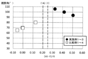
- FIGS. 6 and 7 are graphs showing the first and second comparison results regarding the effect of the visual optical system 12.
- the horizontal axis of FIG. 6 and FIG. 7 is the calculated value of "(H1-Y)/f1" on the right side of equation (1), and the vertical axis is the viewing angle (°).
- the graph in FIG. 6 shows the comparison results of Examples 1 to 3 and Comparative Examples 1 to 4, which have relatively large image heights (e.g., 11 to 13 mm).
- the plots of black circles show the calculation results of Examples 1 to 3 (described below) of the visual optical system 12 of this embodiment.
- the plots of white squares show the calculation results of Examples 1 to 4 of Patent Document 1, which serve as Comparative Examples 1 to 4.
- Comparative Examples 1 to 4 As shown in Figure 6, in Comparative Examples 1 to 4, the calculated values on the horizontal axis are below the lower limit of condition (1A), and Comparative Examples 1 to 4 do not satisfy condition (1A). For this reason, in Comparative Examples 1 to 4, even though the image height is relatively large, the viewing angle is only 80° or less.
- Examples 1 to 3 of the visual optical system 12 of this embodiment as shown in FIG. 6 for example, the calculated value on the horizontal axis is equal to or greater than the lower limit of condition (1A), and condition (1A) is satisfied.
- Examples 1 to 3 of the visual optical system 12 of this embodiment have a field of view exceeding 90°, providing a wider field of view than the comparative example of Patent Document 1, which has a relatively large image height.
- Examples 1 to 3 of this embodiment also satisfy condition (1).
- the graph in Figure 7 shows the comparison results of Examples 4 to 6 (described below) and Comparative Examples 5 to 8, which have relatively small image heights (e.g., 5 to 9 mm).
- the plots of black circles show the calculation results of Examples 4 to 6 of the visual optical system 12 of this embodiment.
- the plots of white triangles show the calculation results of Examples 1 to 4 of Patent Document 2, which serve as Comparative Examples 5 to 8.
- Comparative Examples 5 to 8 do not satisfy condition (1A), and the field of view obtained in Comparative Examples 5 to 8 is less than 60°.
- Examples 4 to 6 of the visual optical system 12 of this embodiment satisfy condition (1A), and the field of view is greater than 80°. In this way, the visual optical system 12 of this embodiment achieves a wider field of view, even compared to Comparative Examples 5 to 8, which have a relatively small image height.
- Examples 4 to 6 of this embodiment also satisfy condition (1).
- the visual optical system 12 of this embodiment has the effect of making it easier to ensure a wide field of view by being configured to satisfy condition (1A). Furthermore, by satisfying condition (1), the visual optical system 12 of this embodiment can more significantly obtain the effect of obtaining a wide field of view with a small visual optical system 12. Furthermore, this effect can also be significantly obtained by configuring the visual optical system 12 of this embodiment to have a relatively stronger power of the first lens group G1 relative to the first and second lens groups G1, G2 (see formula (4)).
- the visual optical system 12 of the present embodiment may satisfy the condition (2) expressed by the following formula. (H1-Y)/f1 ⁇ 0.55...(2)
- the visual optical system 12 of this embodiment can avoid enlarging the lens size by not excessively strengthening the power of the first lens group G1.
- the visual optical system 12 of the present embodiment may satisfy the following conditional expression (3). 0 ⁇
- f is the focal length of the entire visual optical system 12
- f2 is the focal length of the second lens group G2.
- the above formula (3) indicates a criterion for relatively weakening the power of the second lens group G2, for example at the upper limit value, based on the power of the entire visual optical system 12.
- the lower limit value of the above formula (3) indicates a criterion for imparting power to the second lens group G2.
- the visual optical system 12 of this embodiment can easily avoid a situation in which a change in temperature of the second lens group G2 due to heat from the display element 11 affects the performance of the visual optical system 12, and can easily use a resin material, for example, as the lens material of the second lens group G2.
- resin lenses have a tendency for their power to change easily when exposed to high temperatures. Therefore, by weakening the power of the second lens group G2 so that it is below the upper limit value of condition (3), the visual optical system 12 of this embodiment can reduce the performance impact of temperature change even if the second lens group G2 is a resin lens.
- the visual optical system 12 of the present embodiment may satisfy the following conditional expression (4). 0.98 ⁇
- the above formula (4) indicates a criterion for relatively strengthening the power of the first lens group G1, for example at the upper limit, based on the power of the entire visual optical system 12.
- the above formula (4) also indicates a criterion for avoiding excessive strengthening of the power of the first lens group G1, for example at the upper limit.
- the lower limit of the above formula (4) indicates a criterion for avoiding excessive weakening of the power of the first lens group G1.
- Condition (4) allows the visual optical system 12 of this embodiment to appropriately strengthen the power of the first lens group G1 so that it is below the upper limit, for example, making it easier to achieve a wide viewing angle in a small visual optical system 12. Also, the power of the second lens group G2 can be relatively weakened, making it easier to achieve a wide viewing angle as well as reduce the performance effects of temperature changes. Also, exceeding the lower limit of condition (4) makes it easier to avoid the visual optical system 12 becoming larger or the viewing angle becoming narrower.
- the +Z side surface of the third lens element 23 located furthest to the +Z side in the second lens group G2 may satisfy the following formula (5).
- SagH is the amount of sag on the +Z side surface of the third lens element 23.
- the amount of sag SagH is measured, for example, with the effective radius on the +Z side surface of the third lens element 23 as a reference height.
- the above formula (5) indicates, for example, at the upper limit value, the criterion for the shape of the +Z side surface of the third lens element 23 to be close to flat.
- the lower limit value of the above formula (5) indicates the criterion for making the third lens element 23 not completely flat.
- condition (5) for example, by making the +Z side of the third lens element 23 nearly flat so that it is below the upper limit value, the effects of temperature changes on the lens surface can be made uniform from near the center to the periphery, making it easier to reduce the effects on the performance of the visual optical system 12 caused by heat generation from the display element 11.
- FIG. 8 shows surface data of the visual optical system 12 in Numerical Example 1.
- the surface data in FIG. 8 shows information on each surface of the visual optical system 12 through which the display light Bi, B1 to B10 passes, in the order from the emission destination to the emission source display surface S on the -Z side of the pupil A.
- the second and third surfaces are the -Z and +Z sides of the first lens element 21, respectively, and the fourth surface represents the same surface as the second surface based on the reflection of the display light.
- the fifth and sixth surfaces are the -Z and +Z sides of the second lens element 22, respectively, and the seventh and eighth surfaces are the -Z and +Z sides of the third lens element 23, respectively.
- the information for each surface includes, for example, the radius of curvature r of the apex, the surface spacing d (for example, in mm), and the refractive index nd and Abbe number vd of each element with respect to the d line.
- the surface spacing d has a sign corresponding to the ⁇ Z side. Also, in FIG. 8, an "*" is added to the surface number of an aspheric surface.
- Fig. 9 shows aspheric data of the visual optical system 12 in Numerical Example 1.
- the aspheric data in Fig. 9 shows various coefficients of the following equation (10) that defines the shape of the rotationally symmetric aspheric surface for each aspheric surface in Fig. 8.
- h is the height from the optical axis
- z is the amount of sag at height h
- K is the conic constant
- r is the radius of curvature of the apex
- An is the nth-order aspheric coefficient.
- n is an even number between 4 and 10
- the sum is taken for each n.
- the amount of sag z which corresponds to the distance between the point of height h on the target surface and the tangent plane of the apex, is defined so as to have a deviation from a spherical shape according to the aspheric coefficient An.
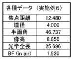
- Figure 10 shows various data of the visual optical system 12 in Numerical Example 1.
- the various data in Figure 10 show the focal length f, pupil diameter, half angle of view, image height, total optical length, and back focus BF of the visual optical system 12 in this Numerical Example.
- the pupil diameter is the diameter of the pupil A.
- the half angle of view corresponds to 1/2 the field of view angle (see ⁇ in Figure 5).
- the back focus BF is, for example, the length in air.
- the units of the various lengths are "mm", and the unit of the half angle of view is "°".
- FIG. 11 is an aberration diagram showing various aberrations of the visual optical system 12 in this numerical example.
- the following aberration diagrams illustrate various longitudinal aberrations in the zero diopter state.
- FIGS. 11(a), (b), and (c) respectively show spherical aberration, astigmatism, and distortion aberration diagrams of the visual optical system 12 in this numerical example.
- the horizontal axis of Fig. 11(a) shows spherical aberration "SA” in mm, and the vertical axis shows normalized pupil height.
- the solid line “d-line” shows d-line characteristics
- the dashed line “g-line” shows g-line characteristics
- the dashed line “C-line” shows C-line characteristics.
- the horizontal axis of Fig. 11(b) shows astigmatism "AST” in mm
- the vertical axis shows image height.
- the solid line “s” shows sagittal plane characteristics
- the dashed line “m” shows meridional plane characteristics.
- the horizontal axis of Fig. 11(c) shows distortion aberration "DIS” in %
- the vertical axis shows image height.
- the visual optical system 12 according to this embodiment can be implemented in various forms, not limited to the above-mentioned Example 1. Below, Examples 2 to 4 of the visual optical system 12 are described.
- Example 2 In the second embodiment, an example in which the eye relief ER is shorter than that of the visual optical system 12 in the first embodiment will be described with reference to FIGS.
- FIG. 12 shows the configuration of the visual optical system 12A according to the second embodiment in the same manner as FIG. 3 of the first embodiment.
- the visual optical system 12A of the second embodiment has the same configuration as the visual optical system 12 of the first embodiment, but various parameters such as the lens shape are changed in response to the shortening of the eye relief ER. This allows, for example, the lens diameter in the visual optical system 12A to be reduced, making it easier to miniaturize the visual optical system 12A.
- Figure 13 shows the surface data of the visual optical system 12A in Numerical Example 2, similar to Figure 8.
- Figure 14 shows the aspheric data in this example, similar to Figure 9.
- Figure 15 shows various data in this example, similar to Figure 10.
- Figure 16 shows various aberrations of the visual optical system 12A in Numerical Example 2.
- Figures 16(a), (b), and (c) show various aberration diagrams of the visual optical system 12A in this embodiment, similar to Figures 11(a), (b), and (c), respectively.
- the visual optical system 12A of this embodiment satisfies conditions (1A) and (1) to (5).
- the visual optical system 12A of this embodiment also provides the same effects as those of Example 1. For example, it is easy for the user 5 of the HMD 1 to ensure that the projection unit 10 is small and that the virtual image V has a good field of view, such as a wide viewing angle.
- Example 3 In the third embodiment, an example in which the eye relief ER is even shorter than that of the visual optical system 12A in the second embodiment will be described with reference to FIGS.
- FIG. 17 shows the configuration of the visual optical system 12B according to Example 3, similar to FIG. 3 of Example 1.
- the visual optical system 12B of this example has the same configuration as the visual optical system 12 of Example 1, but parameters such as the shapes of various aspheric surfaces are changed in response to the shortening of the eye relief ER.
- Figure 18 shows the surface data of the visual optical system 12B in Numerical Example 3, similar to Figure 8.
- Figure 19 shows the aspheric surface data in this example, similar to Figure 9.
- Figure 20 shows various data in this example, similar to Figure 10.
- FIG. 21 shows various aberrations of the visual optical system 12B in Numerical Example 3. Similar to FIGS. 11(a), (b), and (c), FIGS. 21(a), (b), and (c) respectively show various aberration diagrams of the visual optical system 12B in this embodiment. Furthermore, the visual optical system 12B of this embodiment satisfies conditions (1A) and (1) to (5), and this also provides the same effects as in Example 1.
- Example 4 In the fourth embodiment, an example in which the image height is smaller than that of the visual optical system 12 in the first embodiment will be described with reference to FIGS.
- FIG. 22 shows the configuration of the visual optical system 12C according to Example 4, similar to FIG. 3 of Example 1.
- the visual optical system 12C of this example has the same configuration as the visual optical system 12 of Example 1, but various parameters are changed in response to the reduction in the image height on the display surface S.
- Figure 23 shows the surface data of the visual optical system 12C in Numerical Example 4, similar to Figure 8.
- Figure 24 shows the aspheric surface data in this example, similar to Figure 9.
- Figure 25 shows various data in this example, similar to Figure 10.
- Figure 26 shows various aberrations of the visual optical system 12C in Numerical Example 4.
- Figures 26(a), (b), and (c) show various aberration diagrams of the visual optical system 12C in this embodiment, similar to Figures 11(a), (b), and (c), respectively.
- the visual optical system 12C of this embodiment satisfies conditions (1A) and (1) to (5), and this also provides the same effects as in Example 1.
- Example 5 In the fifth embodiment, an example in which the eye relief ER is shorter than that of the visual optical system 12C in the fourth embodiment will be described with reference to FIGS.
- FIG. 27 shows the configuration of the visual optical system 12D according to Example 5, similar to FIG. 3 of Example 1.
- the visual optical system 12D of this example has the same configuration as the visual optical system 12C of Example 4, but various parameters are changed in response to the shortening of the eye relief ER, similar to Example 2.
- Figure 31 shows various aberrations of the visual optical system 12D in Numerical Example 5.
- Figures 31(a), (b), and (c) show various aberration diagrams of the visual optical system 12D in this embodiment, similar to Figures 11(a), (b), and (c), respectively.
- the visual optical system 12D of this embodiment satisfies conditions (1A) and (1) to (5), and this also provides the same effects as in Example 1.
- Figure 36 shows various aberrations of the visual optical system 12E in Numerical Example 6.
- Figures 36(a), (b), and (c) show various aberration diagrams of the visual optical system 12E in this embodiment, similar to Figures 11(a), (b), and (c), respectively.
- the visual optical system 12E of this embodiment satisfies conditions (1A) and (1) to (5), and this also provides the same effects as in Example 1.
- Figure 37 shows the satisfaction of various conditions for the visual optical system 12 according to this embodiment.
- the calculated values for conditional expressions (1) to (5) are shown along with the focal length f1 of the first lens group G1 for each example of the visual optical system 12.
- the visual optical systems 12 and 12A to 12E of Examples 1 to 6 each satisfy the above-mentioned conditions (1) to (5).
- the visual optical systems 12 and 12A to 12E of Examples 1 to 6 also satisfy condition (1A).
- the visual optical system 12 in this embodiment is an example of an eyepiece optical system that guides light between the pupil A of the user 5 and the display surface S.
- the visual optical system 12 includes a first lens group G1 and a second lens group G2 that are arranged in order from the pupil side (-Z side) of the user 5 to the display side (+Z side) facing the display surface S.
- the first lens group G1 includes a first lens element 21 and a second lens element 22 that are arranged in order from the pupil side to the display side, and includes a polarizing reflecting surface 41 on the pupil side of the first lens element 21 and a half mirror 43 between the first lens element 21 and the second lens element 22.
- the second lens group G2 includes a third lens element 23 that has an aspheric surface that is convex toward the pupil side.
- the focal length f1 of the first lens group G1 is less than or equal to five times the difference between the maximum height H1 of the chief ray on the pupil side, which is the pupil side of the first lens element 21 in the first lens group G1, and the maximum image height Y of the display surface S (condition (1A)).
- the visual optical system 12 of this embodiment satisfies the above condition (1A), making it easier to obtain a wide viewing angle, and for example, making it easier to ensure a wide field of view for the user 5 of the HMD 1.
- the visual optical system 12 of the present embodiment may satisfy the above-mentioned condition (1), which makes it easier to ensure a wide viewing angle while using, for example, a small display element 11 or configuring the visual optical system 12 to be compact. 0.25 ⁇ (H1-Y)/f1...(1)
- the visual optical system 12 of the present embodiment may satisfy the above-mentioned condition (2), which makes it easier to reduce the size of the visual optical system 12. (H1-Y)/f1 ⁇ 0.55...(2)
- the visual optical system 12 of this embodiment may satisfy the above-mentioned condition (3). This makes it easier to use a low-cost resin material or the like for the second lens group G2, from the viewpoint of suppressing the performance impact of the visual optical system 12 due to a temperature change of the second lens group G2 caused by heat from the display element 11. Furthermore, it makes it easier to miniaturize the visual optical system 12. 0 ⁇
- the visual optical system 12 of this embodiment may satisfy the above-mentioned condition (4). This makes it possible to relatively strengthen the power of the first lens group G1, to easily ensure a wide viewing angle, and to suppress the performance effects of temperature changes. Furthermore, it makes it easier to miniaturize the visual optical system 12. 0.98 ⁇
- the third lens element 23 may be disposed on the display side in the second lens group G2, and may satisfy the above-mentioned condition (5). This makes it possible to suppress fluctuations in the power of the third lens element 23, which is susceptible to temperature changes due to heat generated by the display element 11, and to suppress effects on the performance of the visual optical system 12. In this way, the cost of the visual optical system 12 can be reduced. 0 ⁇
- the eyepiece optical system of this embodiment may further include a diopter adjustment mechanism 13 as an example of a movable mechanism that moves the first lens group G1 along the optical axis of the visual optical system 12.
- the diopter adjustment mechanism 13 of this embodiment is configured to adjust the diopter of the user 5 by moving the first lens group G1.
- Such a diopter adjustment mechanism 13 can make it easier for the user 5 to use the HMD 1.
- the maximum image height Y of the display surface S may be 20 mm or less. This makes it easier to miniaturize the visual optical system 12. Also, in this embodiment, the maximum image height Y of the display surface S may be 8 mm or more. This makes it easier to ensure a wide viewing angle in the visual optical system 12.
- the visual optical system 12 of this embodiment may further include a quarter-wave plate 42, which is an example of a phase difference element, on the pupil side of the first lens element 21.
- the visual optical system 12 of this embodiment may further include a polarizing element, such as a circular polarizer 44, on the display side of the second lens element 22.
- the HMD 1 is an example of a display device that includes a display element 11 having a display surface S for displaying an image, and an eyepiece optical system 12.
- the visual optical system 12 makes it easier for the user 5 to ensure a clear field of view.
- the HMD 1 of this embodiment may further include a fixing member 14 that is fixed to the head of the user 5 to position the eyepiece optical system 12.
- the display element 11 may be a micro OLED. This makes it easier to achieve high-definition image quality for the virtual image V in the HMD 1.
- the first embodiment has been described as an example of the technology disclosed in this application.
- the technology in this disclosure is not limited to this, and can be applied to embodiments in which modifications, substitutions, additions, omissions, etc. are appropriately performed.
- the visual optical system 12 is described as having two lens elements 21 and 22 as the first lens group G1 and one lens element 23 as the second lens group G2, but the present disclosure is not limited thereto.
- the visual optical system 12 may have three or more lens elements as the first lens group G1, and may have two or more lens elements as the second lens group G2. Increasing the number of lenses in this way facilitates optical design that ensures a wide viewing angle, and the visual optical system of this embodiment can also make it easier to ensure the user's field of view, as in the above embodiment 1.
- the visual optical system 12 of this embodiment may have one or more lens elements between the second lens element 22 and the third lens element 23.
- optical elements without power such as flat plates, may be provided in various locations in the visual optical system 12 of this embodiment.
- the diopter adjustment mechanism 13 has been described as an example of a movable mechanism in the eyepiece optical system.
- the movable mechanism of the eyepiece optical system may move the lens groups of the first and second lens elements 21, 22 in the Z direction for purposes other than diopter adjustment, and may be used for zooming or focusing, for example.
- the HMD 1 is equipped with a visual field adjustment mechanism 13 that is movable in the Z direction.
- the HMD 1 may be equipped with a diopter adjustment means other than the diopter adjustment mechanism 13 that is movable in the Z direction, and may be configured to allow a correction lens for diopter adjustment to be separately attached, for example.
- the polarized reflective surface of the visual optical system 12 reflects p-polarized light and transmits s-polarized light
- the polarized reflective surface is not limited to this.
- the polarized reflective surface may reflect s-polarized light and transmit p-polarized light, or may selectively reflect or transmit circularly polarized light.
- the polarized reflective surface 41 and the quarter-wave plate 42 are used in the visual optical system 12, but the quarter-wave plate 42 may be omitted.
- a rotationally symmetric aspheric surface is used in each of the lens elements 21, 22 of the visual optical system 12.
- a rotationally asymmetric aspheric surface may be used in each of the lens elements 21, 22, and for example, an anamorphic aspheric surface or a free-form surface such as an XY polynomial surface may be used.
- a glasses-type HMD 1 is illustrated as an example of a display device to which the visual optical system 12 is applied, but the present disclosure is not limited to this.
- the HMD 1 is not limited to a glasses-type HMD, but may be a goggle-type HMD, or may be an HMD for monocular vision.
- the display device to which the visual optical system 12 is applied is not limited to an HMD, but may be various types of viewfinders, such as an electronic viewfinder. Even in these various display devices, the visual optical system 12 can make it easier for the user to ensure a clear visual field.
- the first lens element 21 and the second lens element 22 are cemented in the visual optical system 12 .
- the first lens element 21 and the second lens element 22 do not have to be cemented.
- the shape of the +Z side surface of the first lens element 21 and the shape of the -Z side surface of the second lens element 22 do not have to be the same.
- the visual optical system 12 can easily ensure the user's field of vision, similar to the visual optical system 12 of each of the above embodiments, by appropriately configuring the first lens group G1 with a gap between the first lens element 21 and the second lens element 22.
- the first partially reflective surface is a polarized reflective surface 41 and the second partially reflective surface is a half mirror 43 in the visual optical system 12
- the first partially reflective surface does not necessarily have to be a polarized reflective surface 41
- the second partially reflective surface does not necessarily have to be a half mirror 43.
- the first partially reflective surface of this embodiment may be a half mirror.
- the second partially reflective surface of this embodiment may be a polarized reflective surface. Even in such a case, the visual optical system 12 of this embodiment can easily ensure the user's field of vision by using an optical path that travels while folding back and forth between the first and second partially reflective surfaces, just like the visual optical system 12 of each of the above embodiments.
- a first aspect of the present disclosure is an eyepiece optical system that guides light between a user's pupil and a display surface.
- the eyepiece optical system includes a first lens group and a second lens group that are arranged in order from the user's pupil side to the display side facing the display surface.
- the first lens group includes a first lens element and a second lens element that are arranged in order from the pupil side to the display side, and has a first partial reflecting surface on the pupil side of the first lens element and a second partial reflecting surface between the first lens element and the second lens element.
- the second lens group includes a third lens element that has an aspheric surface that is convex toward the pupil side.
- the focal length of the first lens group is 5 times or less the difference between the maximum height of the chief ray on the pupil side surface that is the pupil side of the first lens element in the first lens group and the maximum image height on the display surface.
- H1 is the maximum height of the principal ray on the pupil side surface of the first lens group
- Y is the maximum image height on the display surface
- f1 is the focal length of the first lens group.
- the following condition (3) is satisfied: 0 ⁇
- f is the focal length of the eyepiece optical system
- f2 is the focal length of the second lens group.
- f1 is the focal length of the first lens group.
- the third lens element is disposed on the viewing side in the second lens group, and satisfies the following condition (5): 0 ⁇
- SagH the amount of sag on the display side surface of the third lens element.
- the eyepiece optical system according to any one of the first to sixth aspects further includes a movable mechanism that moves the first lens group along the optical axis of the eyepiece optical system.
- the movable mechanism is configured to move the first lens group to adjust the user's visual acuity.
- the ninth aspect is an eyepiece optical system according to any one of the first to eighth aspects, in which the maximum image height of the display surface is 20 mm or less.
- the tenth aspect is an eyepiece optical system according to any one of the first to ninth aspects, in which the maximum image height of the display surface is 8 mm or more.
- the first lens element and the second lens element are cemented together.
- the first partially reflective surface is a polarizing reflective surface that reflects or transmits incident light depending on the polarization of the light
- the second partially reflective surface is a half mirror that reflects a portion of the incident light and transmits the remainder.
- the eyepiece optical system according to any one of the first to tenth aspects further includes a phase difference element provided on the pupil-side surface of the first lens element, which provides a phase delay of 1/4 wavelength.
- the fourteenth aspect is an eyepiece optical system according to any one of the first to thirteenth aspects, further comprising a circular polarizer provided on the display side surface of the second lens element.
- the fifteenth aspect is a head-mounted display comprising a display element having a display surface for displaying an image, and an eyepiece optical system according to any one of the first to fourteenth aspects.
- a sixteenth aspect is the head mounted display of the fifteenth aspect, in which the display element is a micro organic light emitting diode display.
- the components described in the attached drawings and detailed description may include not only components essential for solving the problem, but also components that are not essential for solving the problem in order to illustrate the above technology. Therefore, the fact that these non-essential components are described in the attached drawings or detailed description should not be used to immediately conclude that these non-essential components are essential.
- the eyepiece optical system disclosed herein can be applied to various display devices, such as HMDs or viewfinders.
Landscapes
- Physics & Mathematics (AREA)
- General Physics & Mathematics (AREA)
- Optics & Photonics (AREA)
- Lenses (AREA)
Priority Applications (2)
| Application Number | Priority Date | Filing Date | Title |
|---|---|---|---|
| JP2025503732A JPWO2024181095A1 (https=) | 2023-02-28 | 2024-02-09 | |
| US19/304,818 US20250370246A1 (en) | 2023-02-28 | 2025-08-20 | Eyepiece optical system and head mounted display |
Applications Claiming Priority (2)
| Application Number | Priority Date | Filing Date | Title |
|---|---|---|---|
| JP2023029850 | 2023-02-28 | ||
| JP2023-029850 | 2023-02-28 |
Related Child Applications (1)
| Application Number | Title | Priority Date | Filing Date |
|---|---|---|---|
| US19/304,818 Continuation US20250370246A1 (en) | 2023-02-28 | 2025-08-20 | Eyepiece optical system and head mounted display |
Publications (1)
| Publication Number | Publication Date |
|---|---|
| WO2024181095A1 true WO2024181095A1 (ja) | 2024-09-06 |
Family
ID=92589684
Family Applications (1)
| Application Number | Title | Priority Date | Filing Date |
|---|---|---|---|
| PCT/JP2024/004551 Ceased WO2024181095A1 (ja) | 2023-02-28 | 2024-02-09 | 接眼光学系およびヘッドマウントディスプレイ |
Country Status (3)
| Country | Link |
|---|---|
| US (1) | US20250370246A1 (https=) |
| JP (1) | JPWO2024181095A1 (https=) |
| WO (1) | WO2024181095A1 (https=) |
Citations (3)
| Publication number | Priority date | Publication date | Assignee | Title |
|---|---|---|---|---|
| JP2020030302A (ja) * | 2018-08-22 | 2020-02-27 | キヤノン株式会社 | 観察光学系及びそれを有する観察装置 |
| CN112558287A (zh) * | 2020-12-30 | 2021-03-26 | 深圳纳德光学有限公司 | 一种折反射式目镜光学系统及头戴显示装置 |
| JP2021081530A (ja) * | 2019-11-18 | 2021-05-27 | キヤノン株式会社 | 観察光学系および光学機器 |
-
2024
- 2024-02-09 JP JP2025503732A patent/JPWO2024181095A1/ja active Pending
- 2024-02-09 WO PCT/JP2024/004551 patent/WO2024181095A1/ja not_active Ceased
-
2025
- 2025-08-20 US US19/304,818 patent/US20250370246A1/en active Pending
Patent Citations (3)
| Publication number | Priority date | Publication date | Assignee | Title |
|---|---|---|---|---|
| JP2020030302A (ja) * | 2018-08-22 | 2020-02-27 | キヤノン株式会社 | 観察光学系及びそれを有する観察装置 |
| JP2021081530A (ja) * | 2019-11-18 | 2021-05-27 | キヤノン株式会社 | 観察光学系および光学機器 |
| CN112558287A (zh) * | 2020-12-30 | 2021-03-26 | 深圳纳德光学有限公司 | 一种折反射式目镜光学系统及头戴显示装置 |
Also Published As
| Publication number | Publication date |
|---|---|
| US20250370246A1 (en) | 2025-12-04 |
| JPWO2024181095A1 (https=) | 2024-09-06 |
Similar Documents
| Publication | Publication Date | Title |
|---|---|---|
| JP7696108B2 (ja) | 接眼光学系および表示装置 | |
| CN110196492B (zh) | 虚像显示装置 | |
| JP7207986B2 (ja) | 画像表示装置、及び、接眼光学系 | |
| US7894138B2 (en) | Display optical system and image display apparatus including the same | |
| US10627644B2 (en) | Virtual image display device | |
| US20250138308A1 (en) | Optical system and display device | |
| US12242061B2 (en) | Optical system and observation apparatus having the same | |
| JP2005099788A (ja) | 非球面を含む画像形成光学系を備えるhmdデバイス | |
| JP4419243B2 (ja) | 斜め投影光学系 | |
| JP7183610B2 (ja) | 虚像表示装置 | |
| CN116626895A (zh) | 虚像显示装置用光学系统、虚像显示装置及头戴式显示器 | |
| JP4419244B2 (ja) | 斜め投影光学系 | |
| JP7438811B2 (ja) | 光学系および画像表示装置 | |
| WO2019065259A1 (ja) | 画像投写装置 | |
| WO2024181095A1 (ja) | 接眼光学系およびヘッドマウントディスプレイ | |
| CN118393732A (zh) | 光学系统和显示装置 | |
| JP3816610B2 (ja) | プリズム光学系 | |
| CN114428429B (zh) | 液晶透镜、透镜模组和近眼显示设备 | |
| WO2025141916A1 (ja) | 光学系及び表示装置 | |
| WO2025037456A1 (ja) | 光学系及び表示装置 | |
| JP2026000499A (ja) | 光学系及びそれを有する観察装置 | |
| KR20250169080A (ko) | 표시 광학계 및 표시 장치 | |
| CN119002058A (zh) | 光学系统和图像显示装置 | |
| JP2025097161A (ja) | 表示光学系および画像表示装置 | |
| CN119439502A (zh) | 显示装置 |
Legal Events
| Date | Code | Title | Description |
|---|---|---|---|
| 121 | Ep: the epo has been informed by wipo that ep was designated in this application |
Ref document number: 24763579 Country of ref document: EP Kind code of ref document: A1 |
|
| ENP | Entry into the national phase |
Ref document number: 2025503732 Country of ref document: JP Kind code of ref document: A |
|
| WWE | Wipo information: entry into national phase |
Ref document number: 2025503732 Country of ref document: JP |
|
| NENP | Non-entry into the national phase |
Ref country code: DE |
|
| 122 | Ep: pct application non-entry in european phase |
Ref document number: 24763579 Country of ref document: EP Kind code of ref document: A1 |