WO2024181014A1 - 被覆工具及び切削工具 - Google Patents
被覆工具及び切削工具 Download PDFInfo
- Publication number
- WO2024181014A1 WO2024181014A1 PCT/JP2024/003393 JP2024003393W WO2024181014A1 WO 2024181014 A1 WO2024181014 A1 WO 2024181014A1 JP 2024003393 W JP2024003393 W JP 2024003393W WO 2024181014 A1 WO2024181014 A1 WO 2024181014A1
- Authority
- WO
- WIPO (PCT)
- Prior art keywords
- layer
- coating layer
- substrate
- coated tool
- based coating
- Prior art date
- Legal status (The legal status is an assumption and is not a legal conclusion. Google has not performed a legal analysis and makes no representation as to the accuracy of the status listed.)
- Ceased
Links
Images


Classifications
-
- B—PERFORMING OPERATIONS; TRANSPORTING
- B23—MACHINE TOOLS; METAL-WORKING NOT OTHERWISE PROVIDED FOR
- B23B—TURNING; BORING
- B23B27/00—Tools for turning or boring machines; Tools of a similar kind in general; Accessories therefor
- B23B27/14—Cutting tools of which the bits or tips or cutting inserts are of special material
-
- C—CHEMISTRY; METALLURGY
- C23—COATING METALLIC MATERIAL; COATING MATERIAL WITH METALLIC MATERIAL; CHEMICAL SURFACE TREATMENT; DIFFUSION TREATMENT OF METALLIC MATERIAL; COATING BY VACUUM EVAPORATION, BY SPUTTERING, BY ION IMPLANTATION OR BY CHEMICAL VAPOUR DEPOSITION, IN GENERAL; INHIBITING CORROSION OF METALLIC MATERIAL OR INCRUSTATION IN GENERAL
- C23C—COATING METALLIC MATERIAL; COATING MATERIAL WITH METALLIC MATERIAL; SURFACE TREATMENT OF METALLIC MATERIAL BY DIFFUSION INTO THE SURFACE, BY CHEMICAL CONVERSION OR SUBSTITUTION; COATING BY VACUUM EVAPORATION, BY SPUTTERING, BY ION IMPLANTATION OR BY CHEMICAL VAPOUR DEPOSITION, IN GENERAL
- C23C16/00—Chemical coating by decomposition of gaseous compounds, without leaving reaction products of surface material in the coating, i.e. chemical vapour deposition [CVD] processes
- C23C16/22—Chemical coating by decomposition of gaseous compounds, without leaving reaction products of surface material in the coating, i.e. chemical vapour deposition [CVD] processes characterised by the deposition of inorganic material, other than metallic material
- C23C16/30—Deposition of compounds, mixtures or solid solutions, e.g. borides, carbides, nitrides
Definitions
- This disclosure relates to coated tools and cutting tools.
- a coated tool (surface-coated sintered alloy) described in Japanese Patent No. 4043145 (Patent Document 1) is known as a coated tool used for cutting tools, etc.
- the coated tool described in Patent Document 1 the surface of the base material is coated with a hard film.
- a diffusion element-containing layer is formed in which iron group metal and tungsten are diffused.
- the non-limiting one-sided coated tool of the present disclosure is a coated tool having a substrate and a coating layer located on the surface of the substrate.
- the coating layer has a Ti-based coating layer.
- the Ti-based coating layer is in contact with the substrate.
- the substrate has a crack extending from the surface toward the inside of the substrate. A portion of the Ti-based coating layer is present in the crack.
- FIG. 1 is a perspective view of a non-limiting one-sided coated tool of the present disclosure.
- 2 is a cross-sectional view perpendicular to the surface of the substrate in the coated tool shown in FIG. 1 .
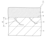
- FIG. 3 is an enlarged view of the vicinity of the boundary between the substrate and the Ti-based coating layer shown in FIG. 2.
- FIG. 1 is a perspective view of a non-limiting one-sided cutting tool of the present disclosure.
- the coated tool 1 may include any component member not shown in each of the drawings referred to.
- the dimensions of the components in each drawing do not faithfully represent the dimensions of the actual components and the dimensional ratios of each component.
- the coated tool 1 may include a base 3 and a coating layer 7 located on a surface 5 of the base 3, as shown in a non-limiting example in Figures 1 and 2.
- the coating layer 7 may have a Ti-based coating layer 9 (titanium-based coating layer).
- the Ti-based coating layer 9 may be in contact with the substrate 3. In other words, the Ti-based coating layer 9 may be coated adjacent to the substrate 3.
- the Ti-based coating layer 9 may also be called a base layer.
- the substrate 3 may have a crack 11, as shown in a non-limiting example in FIG. 3.
- the crack 11 may extend from the surface 5 of the substrate 3 toward the inside of the substrate 3.
- a part of the Ti-based coating layer 9 may be present in the crack 11. In these cases, the adhesion between the substrate 3 and the coating layer 7 is likely to be improved, and chipping resistance and wear resistance are likely to be improved. Therefore, the coated tool 1 has high wear resistance and chipping resistance.
- the presence of a part of the Ti-based coating layer 9 in the crack 11 may mean that a portion that is continuous with the Ti-based coating layer 9 and has the same composition as the Ti-based coating layer 9 is located inside the crack 11.
- the composition being homogeneous may mean that the difference in the respective constituent components is 5% or less.
- the difference in the constituent components may be 3% or less, or may be 1% or less.
- a configuration in which a part of the Ti-based coating layer 9 is present in the crack 11 can also be said to mean that a part of the Ti-based coating layer 9 is present by penetrating into the crack 11.
- the crack 11 can also be called a fissure.
- the crack 11 may open on the surface 5 of the substrate 3.
- the presence of part of the Ti-based coating layer 9 in the crack 11 may be confirmed, for example, by Auger Electron Spectroscopy (AES). Specifically, it may be confirmed by cross-sectional observation using an EDS (Energy Dispersive X-ray Spectroscopy) attached to an electron microscope. Examples of electron microscopes include a scanning electron microscope (SEM) and a transmission electron microscope (TEM).
- this recess can be said to be a crack.
- the cross section in the cross-sectional observation may be a cross section perpendicular to the surface 5 of the substrate 3.
- the area ratio of the Ti-based coating layer 9 inside the crack 11 in the cross section perpendicular to the surface 5 of the substrate 3 may be evaluated.
- this area ratio 100%, it means that the Ti-based coating layer 9 is present throughout the entire inside of the crack 11.
- the above area ratio is 30% or more, it may be considered that a part of the Ti-based coating layer 9 is present in the crack 11.
- there is no particular limit to the upper limit value of the above area ratio For example, there is no problem even if the above area ratio is 100%.
- the substrate 3 may have a first region 13 that exists from the surface 5 toward the inside.
- the first region 13 may have a thickness of 0.5 to 30 ⁇ m.
- the crack 11 may be located in the first region 13.
- the substrate 3 may have a plurality of cracks 11. A portion of the Ti-based coating layer 9 may be present in each of the plurality of cracks 11. In these cases, the adhesion between the substrate 3 and the coating layer 7 is likely to be improved.
- the number of cracks 11 may be measured by cross-sectional observation using an electron microscope. For example, a cross section perpendicular to the surface 5 of the substrate 3 may be photographed at a magnification of 10,000 times using an electron microscope, and the number of cracks 11 present within an area of 8.9 ⁇ m ⁇ 11.8 ⁇ m in the obtained electron microscope photograph may be measured. Multiple photographing locations may be used. For example, the number of photographing locations may be five. The number of cracks 11 may be one to three per field of view in the electron microscope photograph.
- the crack 11 may have a bent portion, as shown in the non-limiting example of FIG. 3.
- the adhesion between the substrate 3 and the coating layer 7 is likely to be improved.
- the crack 11 is bent so as to approach parallel to the surface 5 of the substrate 3, the adhesion between the substrate 3 and the coating layer 7 is likely to be further improved.
- the length of the crack 11 may be the dimension of the crack 11 in the direction in which the crack 11 extends (longitudinal direction).
- the width of the crack 11 may be the dimension of the crack 11 in the direction perpendicular to the direction in which the crack 11 extends (shortitudinal direction).
- the length of the crack 11 may be, for example, 0.5 to 15 ⁇ m.
- the width of the crack 11 may be, for example, 0.05 to 3 ⁇ m as described above. Note that when the base 3 has multiple cracks 11, the length and width of the crack 11 may be average values.
- the average value may be the average value of two cracks 11.
- the substrate 3 may be a sintered alloy.
- the sintered alloy may be made of a cemented carbide.
- the substrate 3 may be made of a cemented carbide.
- the cemented carbide may contain a hard phase and a binder phase.
- the hard phase in the cemented carbide may contain, for example, tungsten carbide (WC).
- the hard phase may contain WC as the main component.
- the cemented carbide may be a WC-based cemented carbide.
- the "main component” may mean the component with the largest mass percentage value compared to other components.
- the binder phase in the cemented carbide may contain an iron group metal.
- iron group metals include cobalt (Co) and nickel (Ni).
- the binder phase in the cemented carbide may contain at least one of Co and Ni.
- the binder phase in the cemented carbide may contain an iron group metal as a main component.
- the binder phase may function as a phase that bonds adjacent hard phases.
- the substrate 3 may be made of a cemented carbide.
- the hard phase may be made of WC or at least one cubic crystal structure compound selected from carbides, nitrides, carbonates, oxynitrides, and their mutual solid solutions of elements in Groups 4, 5, and 6 of the Periodic Table and WC.
- the binder phase may be mainly composed of Co and/or Ni.
- the substrate 3 may be made of cemented carbide.
- the amount of nitrogen (N) contained in the cracks 11 may be 2 mass% or more.
- the nitrogen content in the portion of the Ti-based coating layer 9 located at the cracks 11 may be 2 mass% or more. In this case, wear resistance and chipping resistance are likely to be improved.
- the amount of nitrogen contained in the cracks 11 may be 2 to 30 mass%.
- the amount of carbon (C) contained in the cracks 11 may be 2 to 30 mass%. In other words, the carbon content in the portion of the Ti-based coating layer 9 located in the cracks 11 may be 2 to 30 mass%.
- EDS When performing a compositional analysis of the cracks 11, EDS may be used. In EDS, compositional analysis may be performed with an acceleration voltage of 20 kV and elements selected as Ti, C, N, W, and Co. Compositional analysis of the cracks 11 may also be performed by cross-sectional observation, or by measuring any five locations and calculating the average value. If the substrate 3 is made of cemented carbide, the cracks 11 to be measured may be selected to be located at the boundaries between adjacent WC particles. This is also true when measuring the number of cracks 11.
- the sintered alloy may be made of a cermet.
- the substrate 3 may be made of a cermet.
- the cermet may contain a hard phase and a binder phase.
- the hard phase in the cermet may contain, for example, a titanium (Ti) compound. Examples of Ti compounds include titanium carbonitride (TiCN), titanium carbide (TiC), and titanium nitride (TiN).
- Ti compounds include titanium carbonitride (TiCN), titanium carbide (TiC), and titanium nitride (TiN).
- the hard phase in the cermet may also contain a Ti compound as a main component. In other words, the cermet may be a Ti-based cermet.
- the binder phase in the cermet may contain an iron group metal.
- the binder phase in the cermet may contain at least one of Co and Ni.
- the binder phase in the cermet may contain an iron group metal as a main component.
- the composition of the substrate 3 may be measured, for example, by EDS.
- the measurement may be performed using an EDS attached to an electron microscope.
- the Ti-based coating layer 9 may be a single layer, or may have a laminated structure in which multiple layers are stacked. Examples of the composition of the Ti-based coating layer 9 include TiN and TiC. For example, when the Ti-based coating layer 9 is a single layer, the Ti-based coating layer 9 may be a TiN layer.
- the Ti-based coating layer 9 may have a structure in which three or more TiN layers and TiC layers are alternately laminated.
- the layer closest to the substrate 3 may be a TiN layer. That is, the Ti-based coating layer 9 may have a laminated structure in which at least three TiN layers and TiC layers are alternately laminated, and the layer closest to the substrate 3 in the laminated structure may be a TiN layer. In these cases, wear resistance and chipping resistance are likely to be improved.
- the number of laminated layers may be set to 3 to 8.
- the coating layer 7 is not limited to a specific thickness.
- the average thickness of the Ti-based coating layer 9 may be set to 0.1 to 1 ⁇ m.
- the thickness of the Ti-based coating layer 9 is the value excluding the portion present in the crack 11.
- the thickness of the Ti-based coating layer 9 shown as an example is the overall thickness.
- the thickness of each layer may be the same or different.
- the thickness of the coating layer 7 may be measured by cross-sectional observation using an electron microscope. For example, the thickness may be measured at 10 or more measurement points at any position of the Ti-based coating layer 9, and the average value may be calculated. This is the same for the other layers described below.
- the coating layer 7 may have, in order from the substrate 3, a Ti-based coating layer 9, a first TiCN layer 15, a second TiCN layer 17, a TiCNO layer 19 (titanium carbonate nitride layer), and an Al2O3 layer 21 (alumina layer). In this case, the life of the coated tool 1 is likely to be long.
- the first TiCN layer 15 may be a so-called MT (moderate temperature)-TiCN layer.
- the first TiCN layer 15 may have an average thickness of 2 to 15 ⁇ m. In this case, the first TiCN layer 15 has high wear resistance and chipping resistance.
- the titanium carbonitride crystals contained in the first TiCN layer 15 may be columnar crystals that are elongated in the thickness direction of the coating layer 7.
- the first TiCN layer 15 may be in contact with the Ti-based coating layer 9.
- the second TiCN layer 17 may be a so-called HT (high temperature)-TiCN layer.
- the second TiCN layer 17 may have an average thickness set to 10 to 900 nm.
- the second TiCN layer 17 may be in contact with the first TiCN layer 15.
- the TiCNO layer 19 may have an average thickness of 200 to 2000 nm. In this case, the hardness of the TiCNO layer 19 is less likely to decrease. Also, the Al 2 O 3 layer 21 is more likely to have an ⁇ -type crystal structure. The TiCNO layer 19 may be in contact with the second TiCN layer 17.
- the Al 2 O 3 layer 21 may have an average thickness of 1 to 15 ⁇ m.
- the average thickness of the Al 2 O 3 layer 21 may be greater than the average thickness of the TiCNO layer 19.
- the Al 2 O 3 layer 21 may be in contact with the TiCNO layer 19.
- the coating layer 7 may be located on the entire surface 5 of the substrate 3, or may be located on only a portion of the surface 5. In other words, the coating layer 7 may be located on at least a portion of the surface 5 of the substrate 3.
- the coating layer 7 may be formed by a chemical vapor deposition (CVD) method.
- the coating layer 7 may be a CVD film.
- the coating layer 7 may be a physical vapor deposition (PVD) film formed by a PVD method.
- a cutting insert is shown as a non-limiting example of the coated tool 1. Note that the form of the coated tool 1 is not limited to a cutting insert.
- the coated tool 1 may have a first surface 23 (top surface), a second surface 25 (side surface) adjacent to the first surface 23, and a cutting edge 27 located at the intersection of the first surface 23 and the second surface 25.
- the first surface 23 may be a rake surface.
- the first surface 23 may be a rake surface in its entirety, or only a portion of it may be a rake surface.
- the area of the first surface 23 along the cutting edge 27 may be a rake surface.
- the second surface 25 may be a flank.
- the second surface 25 may be a flank in its entirety, or only a portion of it may be a flank.
- the area of the second surface 25 along the cutting edge 27 may be a flank.
- the cutting edge 27 may be located over the entire intersection of the first surface 23 and the second surface 25, or may be located over only a portion of this intersection.
- the cutting edge 27 can be used to cut a workpiece when manufacturing a machined product using the coated tool 1.
- the coated tool 1 may have a through hole 29.
- the through hole 29 can be used to attach a screw or a clamp member when fixing the coated tool 1 to a holder.
- the through hole 29 may be formed from the first surface 23 to the surface (lower surface) located opposite the first surface 23, and may open in these surfaces. Note that there is no problem even if the through holes 29 are configured to open in mutually opposing areas of the second surface 25.
- the coated tool 1 may have a rectangular plate shape. Note that the shape of the coated tool 1 is not limited to a rectangular plate shape.
- the first surface 23 may have a triangular, pentagonal, hexagonal, or circular shape.
- the coated tool 1 is not limited to a specific size.
- the length of one side of the first surface 23 may be set to approximately 3 to 20 mm.
- the height from the first surface 23 to the surface (lower surface) located on the opposite side of the first surface 23 may be set to approximately 5 to 20 mm.
- a substrate When manufacturing a coated tool, a substrate may be prepared first. An example will be described in which a substrate made of a sintered alloy is prepared as the substrate. First, a mixed powder may be obtained by adding metal powder, carbon powder, etc. to inorganic powder such as carbide, nitride, carbonitride, or oxide, which can be used to form a substrate by firing, and mixing them. Next, this mixed powder may be molded into a predetermined tool shape by a known molding method such as press molding, casting, extrusion, or cold isostatic pressing. The obtained molded body may then be fired in a vacuum or a non-oxidizing atmosphere to obtain a substrate made of a sintered alloy.
- inorganic powder such as carbide, nitride, carbonitride, or oxide
- the surface of the obtained substrate may be subjected to honing (polishing). Honing may be performed by blasting, with an air pressure of 0.1 to 0.3 MPa and a slurry concentration of 5 to 15% by mass. In this case, cracks extending from the surface of the substrate toward the inside of the substrate are likely to form.
- a coating layer may be formed on the surface of the obtained substrate by a CVD method to obtain a coated tool.
- the coating layer may have, in order from the substrate, a Ti-based coating layer, a first TiCN layer (MT-TiCN layer), a second TiCN layer (HT-TiCN layer), a TiCNO layer, and an Al2O3 layer, and the respective deposition conditions will be described in order.
- a mixed gas containing 0.5 to 10 volume % titanium tetrachloride (TiCl 4 ) gas, 10 to 60 volume % nitrogen (N 2 ) gas, and the remainder hydrogen (H 2 ) gas may be prepared as the reaction gas composition. Then, this mixed gas may be introduced into the chamber, and the film formation temperature may be set to 790 to 940° C. and the pressure may be set to 8 to 50 kPa to form the TiN layer.
- a mixed gas containing 0.5 to 10 volume % titanium tetrachloride (TiCl 4 ) gas, 5 to 30 volume % methane (CH 4 ) gas, and the remainder hydrogen (H 2 ) gas may be prepared as the reactive gas composition. Then, this mixed gas may be introduced into the chamber, and the film formation temperature may be set to 790 to 940° C. and the pressure may be set to 8 to 50 kPa to form the TiC layer.
- TiN layers and TiC layers When at least three TiN layers and TiC layers are alternately stacked, the deposition of TiN layers and TiC layers may be repeated alternately.
- the gas forming the Ti-based coating layer may be intentionally allowed to penetrate into the crack, causing part of the Ti-based coating layer to be present in the crack.
- the Ti-based coating layer is a single layer such as a TiN layer
- setting the deposition temperature to a low temperature of 790-820°C will cause the Ti-based coating particles to become finer, making it easier for them to penetrate into the crack.
- the Ti-based coating layer has a layered structure in which at least three TiN layers and TiC layers are alternately laminated, the Ti-based coating particles will become finer, making it easier for them to penetrate into the crack. Note that when the Ti-based coating layer is simply formed, gas is less likely to penetrate into the crack.
- the first TiCN layer (MT-TiCN layer) may be formed as follows. First, a mixed gas consisting of 0.5 to 10 volume % titanium tetrachloride (TiCl 4 ) gas, 5 to 60 volume % nitrogen (N 2 ) gas, 0.1 to 3 volume % acetonitrile (CH 3 CN) gas, and the remainder hydrogen (H 2 ) gas may be adjusted as the reaction gas composition. Then, this mixed gas may be introduced into the chamber, the film formation temperature may be set to a relatively low temperature of 780 to 880° C., and the pressure may be set to 5 to 25 kPa, to form the first TiCN layer.
- a mixed gas consisting of 0.5 to 10 volume % titanium tetrachloride (TiCl 4 ) gas, 5 to 60 volume % nitrogen (N 2 ) gas, 0.1 to 3 volume % % acetonitrile (CH 3 CN) gas, and the remainder hydrogen (H 2 ) gas may be adjusted as the reaction gas
- the average crystal width of the titanium carbonitride columnar crystals constituting the first TiCN layer is likely to be larger on the surface side than on the substrate side.
- the second TiCN layer (HT-TiCN layer) may be formed as follows. First, a mixed gas consisting of 1 to 4 volume % titanium tetrachloride (TiCl 4 ) gas, 5 to 20 volume % nitrogen (N 2 ) gas, 0.1 to 10 volume % methane (CH 4 ) gas, and the remainder hydrogen (H 2 ) gas may be prepared as a reaction gas composition. Then, this mixed gas may be introduced into a chamber, and the film formation temperature may be set to 900 to 990° C. and the pressure may be set to 5 to 40 kPa to form the second TiCN layer. The second TiCN layer may be formed at a higher temperature than the first TiCN layer.
- TiCl 4 titanium tetrachloride
- N 2 nitrogen
- CH 4 0.1 to 10 volume % methane
- H 2 hydrogen
- the TiCNO layer may be formed as follows. First, a mixed gas containing 3 to 15 volume percent titanium tetrachloride (TiCl 4 ) gas, 3 to 50 volume percent nitrogen (N 2 ) gas, 0.5 to 15 volume percent methane (CH 4 ) gas, 0.5 to 10 volume percent carbon monoxide (CO) gas, and the remainder hydrogen (H 2 ) gas may be prepared as the reactive gas composition. Then, this mixed gas may be introduced into a chamber, and the film formation temperature may be set to 900 to 1010° C. and the pressure may be set to 5 to 40 kPa to form the TiCNO layer.
- TiCl 4 titanium tetrachloride
- N 2 nitrogen
- CH 4 methane
- CO carbon monoxide
- H 2 hydrogen
- the Al 2 O 3 layer may be formed as follows. First, a mixed gas may be prepared as a reaction gas composition, which is 3.5 to 15 volume % aluminum trichloride (AlCl 3 ) gas, 0.5 to 2.5 volume % hydrogen chloride (HCl) gas, 0.5 to 5 volume % carbon dioxide (CO 2 ) gas, 0 to 1 volume % hydrogen sulfide (H 2 S) gas, and the remainder hydrogen (H 2 ) gas. Then, this mixed gas may be introduced into a chamber, and the film formation temperature may be set to 900 to 1010°C and the pressure may be set to 5 to 20 kPa to form the Al 2 O 3 layer.
- AlCl 3 aluminum trichloride
- HCl hydrogen chloride
- CO 2 carbon dioxide
- H 2 S hydrogen sulfide
- H 2 S hydrogen sulfide
- coated tools are not limited to those manufactured by the above manufacturing method.
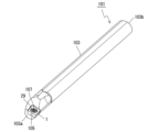
- the cutting tool 101 may include a holder 103 and a coated tool 1, as shown in a non-limiting example in FIG. 4.
- the holder 103 may extend from a first end 103a toward a second end 103b, and may have a pocket 105 on the side of the first end 103a.
- the coated tool 1 may be located in the pocket 105.
- the coated tool 1 has high wear resistance and chipping resistance, enabling stable cutting.
- the pocket 105 may be a portion in which the coated tool 1 is attached.
- the pocket 105 may open on the outer peripheral surface of the holder 103 and on the end surface on the side of the first end 103a.
- the coated tool 1 may be attached to the pocket 105 so that at least a part of the cutting edge 27 protrudes from the holder 103.
- the coated tool 1 may also be attached to the pocket 105 by a screw 107. That is, the coated tool 1 may be attached to the pocket 105 by inserting the screw 107 into the through hole 29 of the coated tool 1 and inserting the tip of the screw 107 into a screw hole formed in the pocket 105 to fix the screw 107 in the screw hole.
- the bottom surface of the coated tool 1 may be in direct contact with the pocket 105, or a sheet may be sandwiched between the coated tool 1 and the pocket 105.
- the material of the holder 103 may be, for example, steel or cast iron. If the material of the holder 103 is steel, the holder 103 has high toughness.
- a cutting tool 101 used for so-called turning is illustrated.
- Examples of turning include internal diameter machining, external diameter machining, and groove machining.
- the cutting tool 101 (coated tool 1) is not limited to use for turning. For example, there is no problem in using the coated tool 1 for the cutting tool 101 used for turning.
- the coated tool 1 is used as the cutting tool 101, but the coated tool 1 can be used for other purposes.
- examples of other uses include wear-resistant parts such as sliding parts or dies, tools such as drilling tools and blades, and impact-resistant parts.
- the coated tool 1 and the cutting tool 101 may have the following configuration.
- a coated tool comprising a base and a coating layer located on a surface of the base, the coating layer having a Ti-based coating layer in contact with the base, the base having a crack extending from the surface toward the inside of the base, and a part of the Ti-based coating layer present in the crack.
- the substrate may be a sintered alloy made of cemented carbide or cermet containing a hard phase and a binder phase.
- the substrate may be made of a cemented carbide containing a hard phase and a binder phase
- the hard phase may be made of tungsten carbide or tungsten carbide and at least one cubic crystal structure compound selected from carbides, nitrides, carbonates, oxynitrides and mutual solid solutions of elements of Groups 4, 5 and 6 of the Periodic Table
- the binder phase may be mainly composed of cobalt and/or nickel.
- the substrate may be made of a cemented carbide containing a hard phase and a binder phase, and the amount of nitrogen contained in the cracks may be 2 mass % or more.
- the amount of carbon contained in the cracks may be 2 to 30 mass %.
- the Ti-based coating layer may have a laminated structure in which at least three TiN layers and TiC layers are alternately laminated, and the layer in the laminated structure closest to the substrate may be the TiN layer.
- the coating layer may have, in order from the substrate, the Ti-based coating layer, a first TiCN layer, a second TiCN layer, a TiCNO layer and an Al 2 O 3 layer.
- the cutting tool may include a holder extending from a first end toward a second end and having a pocket on the side of the first end, and a coated tool according to any one of (1) to (7) above, located in the pocket.
- a substrate was prepared. Specifically, 7% by mass of metal cobalt powder with an average particle size of 1.2 ⁇ m, 2% by mass of titanium carbide powder with an average particle size of 2 ⁇ m, 1% by mass of niobium carbide powder with an average particle size of 2 ⁇ m, 3% by mass of tantalum carbide with an average particle size of 1.2 ⁇ m, 1% by mass of zirconium carbide with an average particle size of 1.2 ⁇ m, and the remainder of the powder with an average particle size of tungsten carbide were mixed to obtain a mixed powder. The average particle size of each powder was measured by a microtrack method.
- the resulting mixed powder was then press molded into a tool shape (CNMG120408) to obtain a molded body.
- the resulting molded body was then subjected to a binder removal process and then fired in a non-oxidizing atmosphere to obtain a base body made of cemented carbide.
- the firing temperature was set to 1450°C
- the firing time was set to 1 hour
- an argon atmosphere was used as the non-oxidizing atmosphere.
- the composition of the obtained cemented carbide was measured by EDS. Specifically, cross-sections were observed using an EDS attached to an SEM at a magnification of 5,000 to 20,000 times, and the average value of measurements at five locations was measured. Five elements were selected for measurement using EDS: tungsten carbide, cobalt, titanium, carbon, and nitrogen.
- the obtained cemented carbide contained a hard phase and a binder phase. More specifically, the obtained cemented carbide contained a hard phase made of WC and a binder phase mainly composed of Co.
- Honing was performed by blasting with an air pressure of 0.1 to 0.3 MPa and a slurry concentration of 5 to 15% by mass.
- the cross section of the substrate after honing was observed using an SEM. As a result, the substrate had multiple cracks.
- a coating layer was formed on the surface of the obtained substrate by a CVD method to obtain the coated tool samples shown in Table 1.
- a Ti-based coating layer was first formed on the surface of the substrate, and a first TiCN layer (MT-TiCN layer), a second TiCN layer (HT-TiCN layer), a TiCNO layer, and an Al2O3 layer were formed in this order on the Ti-based coating layer.
- the respective deposition conditions were as follows:
- the mixed gas of the TiC layer was first adjusted. Specifically, the reaction gas composition of the TiC layer was adjusted to be a mixed gas consisting of 2 volume % titanium tetrachloride (TiCl 4 ) gas, 10 volume % methane (CH 4 ) gas, and the remainder hydrogen (H 2 ) gas. The same mixed gas as that used for forming a single TiN layer was used as the mixed gas of the TiN layer. Then, these mixed gases were alternately introduced into the chamber so as to have the composition shown in Table 1, and the film formation temperature, pressure, and film formation time were set to the conditions shown in Table 1.
- TiCl 4 titanium tetrachloride
- CH 4 volume % methane
- H 2 remainder hydrogen
- TiN-TiC-TiN means that a TiN layer, a TiC layer, and a TiN layer are laminated in that order from the substrate.
- the deposition temperature and pressure are the same for the TiN layer and the TiC layer.
- the deposition time shown in Table 1 is the total deposition time for each layer.
- the deposition time for each layer is calculated from the formula: (deposition time)/(number of layers).
- a mixed gas was prepared as a reaction gas composition, which consisted of 4 volume % titanium tetrachloride ( TiCl4 ) gas, 20 volume % nitrogen ( N2 ) gas, 8 volume % methane ( CH4 ) gas, 2 volume % carbon monoxide (CO) gas, and the remainder hydrogen ( H2 ) gas.
- TiCl4 titanium tetrachloride
- N2 nitrogen
- CH4 methane
- CO carbon monoxide
- H2 hydrogen
- a mixed gas was prepared as a reaction gas composition, which was composed of 3.7 volume % aluminum trichloride ( AlCl3 ) gas, 0.7 volume % hydrogen chloride (HCl) gas, 4.3 volume % carbon dioxide ( CO2 ) gas, 0.3 volume % hydrogen sulfide ( H2S ) gas, and the remainder hydrogen ( H2 ) gas. Then, this mixed gas was introduced into the chamber, and the film formation temperature was set to 950°C and the pressure was set to 7.5 kPa. The film formation time was set to 380 minutes.
- Samples No. 1 to 3 showed higher wear resistance and chipping resistance than samples No. 4 to 5.
Landscapes
- Chemical & Material Sciences (AREA)
- Engineering & Computer Science (AREA)
- Mechanical Engineering (AREA)
- Inorganic Chemistry (AREA)
- General Chemical & Material Sciences (AREA)
- Chemical Kinetics & Catalysis (AREA)
- Materials Engineering (AREA)
- Metallurgy (AREA)
- Organic Chemistry (AREA)
- Cutting Tools, Boring Holders, And Turrets (AREA)
- Chemical Vapour Deposition (AREA)
Priority Applications (2)
| Application Number | Priority Date | Filing Date | Title |
|---|---|---|---|
| CN202480005322.7A CN120265404A (zh) | 2023-03-02 | 2024-02-02 | 涂层刀具和切削刀具 |
| JP2025503676A JPWO2024181014A1 (https=) | 2023-03-02 | 2024-02-02 |
Applications Claiming Priority (2)
| Application Number | Priority Date | Filing Date | Title |
|---|---|---|---|
| JP2023031807 | 2023-03-02 | ||
| JP2023-031807 | 2023-03-02 |
Publications (1)
| Publication Number | Publication Date |
|---|---|
| WO2024181014A1 true WO2024181014A1 (ja) | 2024-09-06 |
Family
ID=92589605
Family Applications (1)
| Application Number | Title | Priority Date | Filing Date |
|---|---|---|---|
| PCT/JP2024/003393 Ceased WO2024181014A1 (ja) | 2023-03-02 | 2024-02-02 | 被覆工具及び切削工具 |
Country Status (3)
| Country | Link |
|---|---|
| JP (1) | JPWO2024181014A1 (https=) |
| CN (1) | CN120265404A (https=) |
| WO (1) | WO2024181014A1 (https=) |
Citations (4)
| Publication number | Priority date | Publication date | Assignee | Title |
|---|---|---|---|---|
| JP2005186221A (ja) * | 2003-12-25 | 2005-07-14 | Kyocera Corp | 表面被覆切削工具 |
| WO2005092608A1 (ja) * | 2004-03-29 | 2005-10-06 | Kyocera Corporation | 表面被覆部材および切削工具 |
| JP2014172157A (ja) * | 2013-03-12 | 2014-09-22 | Mitsubishi Materials Corp | 表面被覆切削工具 |
| JP2015188995A (ja) * | 2014-03-28 | 2015-11-02 | 三菱マテリアル株式会社 | 耐異常損傷性に優れた表面被覆切削工具 |
-
2024
- 2024-02-02 CN CN202480005322.7A patent/CN120265404A/zh active Pending
- 2024-02-02 JP JP2025503676A patent/JPWO2024181014A1/ja active Pending
- 2024-02-02 WO PCT/JP2024/003393 patent/WO2024181014A1/ja not_active Ceased
Patent Citations (4)
| Publication number | Priority date | Publication date | Assignee | Title |
|---|---|---|---|---|
| JP2005186221A (ja) * | 2003-12-25 | 2005-07-14 | Kyocera Corp | 表面被覆切削工具 |
| WO2005092608A1 (ja) * | 2004-03-29 | 2005-10-06 | Kyocera Corporation | 表面被覆部材および切削工具 |
| JP2014172157A (ja) * | 2013-03-12 | 2014-09-22 | Mitsubishi Materials Corp | 表面被覆切削工具 |
| JP2015188995A (ja) * | 2014-03-28 | 2015-11-02 | 三菱マテリアル株式会社 | 耐異常損傷性に優れた表面被覆切削工具 |
Also Published As
| Publication number | Publication date |
|---|---|
| JPWO2024181014A1 (https=) | 2024-09-06 |
| CN120265404A (zh) | 2025-07-04 |
Similar Documents
| Publication | Publication Date | Title |
|---|---|---|
| US10717135B2 (en) | Coated tool | |
| JP7037581B2 (ja) | 被覆工具およびそれを備えた切削工具 | |
| JP2010253594A (ja) | 表面被覆工具 | |
| JP7037580B2 (ja) | 被覆工具およびこれを備えた切削工具 | |
| JP7301969B2 (ja) | 被覆工具およびそれを備えた切削工具 | |
| CN115315330B (zh) | 涂层刀具 | |
| JP7851394B2 (ja) | 超硬合金およびこれを用いた被覆工具、切削工具 | |
| WO2024181014A1 (ja) | 被覆工具及び切削工具 | |
| JP7805459B2 (ja) | 被覆工具および切削工具 | |
| JP7037582B2 (ja) | 被覆工具およびこれを備えた切削工具 | |
| JP7791317B2 (ja) | 被覆工具および切削工具 | |
| JP7851412B2 (ja) | 被覆工具および切削工具 | |
| WO2024247604A1 (ja) | 被覆工具及び切削工具 | |
| WO2024247600A1 (ja) | 被覆工具及び切削工具 | |
| WO2025197502A1 (ja) | 被覆工具及び切削工具 | |
| WO2024181015A1 (ja) | 超硬合金、被覆工具及び切削工具 | |
| WO2024181016A1 (ja) | 超硬合金、被覆工具及び切削工具 | |
| WO2025192090A1 (ja) | 被覆工具及び切削工具 | |
| JP7441177B2 (ja) | 被覆工具およびそれを備えた切削工具 | |
| JP7431946B2 (ja) | 被覆工具 | |
| WO2025192091A1 (ja) | 被覆工具及び切削工具 | |
| JP6946613B1 (ja) | 切削工具 | |
| WO2025192092A1 (ja) | 超硬合金、被覆工具及び切削工具 | |
| WO2026083717A1 (ja) | 被覆工具及び切削工具 | |
| CN110769957B (zh) | 涂层刀具、切削刀具和切削加工物的制造方法 |
Legal Events
| Date | Code | Title | Description |
|---|---|---|---|
| 121 | Ep: the epo has been informed by wipo that ep was designated in this application |
Ref document number: 24763498 Country of ref document: EP Kind code of ref document: A1 |
|
| WWE | Wipo information: entry into national phase |
Ref document number: 202480005322.7 Country of ref document: CN |
|
| WWE | Wipo information: entry into national phase |
Ref document number: 2025503676 Country of ref document: JP |
|
| WWP | Wipo information: published in national office |
Ref document number: 202480005322.7 Country of ref document: CN |
|
| NENP | Non-entry into the national phase |
Ref country code: DE |
|
| 122 | Ep: pct application non-entry in european phase |
Ref document number: 24763498 Country of ref document: EP Kind code of ref document: A1 |