WO2024180868A1 - 樹脂接合体 - Google Patents
樹脂接合体 Download PDFInfo
- Publication number
- WO2024180868A1 WO2024180868A1 PCT/JP2023/044817 JP2023044817W WO2024180868A1 WO 2024180868 A1 WO2024180868 A1 WO 2024180868A1 JP 2023044817 W JP2023044817 W JP 2023044817W WO 2024180868 A1 WO2024180868 A1 WO 2024180868A1
- Authority
- WO
- WIPO (PCT)
- Prior art keywords
- resin
- resin member
- joint
- bonded body
- recess
- Prior art date
- Legal status (The legal status is an assumption and is not a legal conclusion. Google has not performed a legal analysis and makes no representation as to the accuracy of the status listed.)
- Ceased
Links
Images




Classifications
-
- B—PERFORMING OPERATIONS; TRANSPORTING
- B29—WORKING OF PLASTICS; WORKING OF SUBSTANCES IN A PLASTIC STATE IN GENERAL
- B29C—SHAPING OR JOINING OF PLASTICS; SHAPING OF MATERIAL IN A PLASTIC STATE, NOT OTHERWISE PROVIDED FOR; AFTER-TREATMENT OF THE SHAPED PRODUCTS, e.g. REPAIRING
- B29C65/00—Joining or sealing of preformed parts, e.g. welding of plastics materials; Apparatus therefor
- B29C65/02—Joining or sealing of preformed parts, e.g. welding of plastics materials; Apparatus therefor by heating, with or without pressure
- B29C65/08—Joining or sealing of preformed parts, e.g. welding of plastics materials; Apparatus therefor by heating, with or without pressure using ultrasonic vibrations
-
- B—PERFORMING OPERATIONS; TRANSPORTING
- B29—WORKING OF PLASTICS; WORKING OF SUBSTANCES IN A PLASTIC STATE IN GENERAL
- B29C—SHAPING OR JOINING OF PLASTICS; SHAPING OF MATERIAL IN A PLASTIC STATE, NOT OTHERWISE PROVIDED FOR; AFTER-TREATMENT OF THE SHAPED PRODUCTS, e.g. REPAIRING
- B29C65/00—Joining or sealing of preformed parts, e.g. welding of plastics materials; Apparatus therefor
- B29C65/48—Joining or sealing of preformed parts, e.g. welding of plastics materials; Apparatus therefor using adhesives, i.e. using supplementary joining material; solvent bonding
- B29C65/52—Joining or sealing of preformed parts, e.g. welding of plastics materials; Apparatus therefor using adhesives, i.e. using supplementary joining material; solvent bonding characterised by the way of applying the adhesive
-
- B—PERFORMING OPERATIONS; TRANSPORTING
- B32—LAYERED PRODUCTS
- B32B—LAYERED PRODUCTS, i.e. PRODUCTS BUILT-UP OF STRATA OF FLAT OR NON-FLAT, e.g. CELLULAR OR HONEYCOMB, FORM
- B32B5/00—Layered products characterised by the non- homogeneity or physical structure, i.e. comprising a fibrous, filamentary, particulate or foam layer; Layered products characterised by having a layer differing constitutionally or physically in different parts
- B32B5/18—Layered products characterised by the non- homogeneity or physical structure, i.e. comprising a fibrous, filamentary, particulate or foam layer; Layered products characterised by having a layer differing constitutionally or physically in different parts characterised by features of a layer of foamed material
Definitions
- This disclosure relates to a resin bonded body in which overlapping resin members are bonded together.
- spot welding has been used to join resin parts made of thermoplastic resin.
- resin parts are joined by ultrasonic welding. That is, in spot welding, a horn with a protrusion at its tip is pressed against the main surfaces of multiple overlapping resin parts and vibrated. The vibration of the horn fuses the interface between the resin parts. In this way, the overlapping resin parts are joined.
- Spot welding is a welding method that allows relatively free design of the shape of the resin parts to be joined. For example, with spot welding, when joining resin parts, it is not necessary to provide the surface of the resin parts with a joint shape required for welding, such as a protrusion called an energy director.
- Patent Document 1 discloses a joining structure for joining a first member made of a first resin to a second member made of a second resin having a higher foaming ratio than the first resin.
- the joining structure has a concave joining portion that reaches at least the inside of the first member from the outer surface side of the second member when the first member and the second member are overlapped.
- the concave joining portion is a fusion hole formed by a protrusion of a welding horn.
- the first member is joined to the second member by a heat-welded portion formed at the joining interface with the second member (see Figures 2 and 3 of Patent Document 1).
- Patent Document 2 JP 2018-149765 A discloses an ultrasonic resin welding and fixing structure.
- the ultrasonic resin welding and fixing structure includes a first resin plate and a second resin plate that are in contact with each other, a molten hole that penetrates the first resin plate to form a recess in the second resin plate, and a welding portion formed by welding at least the resin material of the first resin plate to the inner wall of the molten hole.
- the molten hole is formed so as to be inclined with respect to the main surface of the second resin plate that contacts the first resin plate.
- the recess has an inclined surface that inclines toward the bottom side of the recess.
- the welding portion is welded to the inclined surface.
- the heat welded portion formed at the joining interface between the first and second members does not have sufficient joining strength against a tensile load in a direction along the joining interface.
- the welding hole must be formed so as to be inclined with respect to the main surface of the second resin plate that contacts the first resin plate. In other words, compared to when the welding hole is formed in a direction perpendicular to the main surface of the second resin plate that contacts the first resin plate, it is difficult for the vibration from the horn to be transmitted to the surface of the first resin plate. Therefore, even when the welding hole is formed in a direction perpendicular to the main surface of the second resin plate that contacts the first resin plate, a resin joined body with excellent joining strength is required.
- the objective of this disclosure is to provide a resin bonded body with excellent bonding strength.
- the resin bonded body according to the present disclosure may include a first resin member made of foamed resin, a second resin member bonded to the first resin member, and a bonding portion bonding the first resin member and the second resin member.
- the bonding portion may include a molten hole penetrating the second resin member to form a recess in the first resin member, a concave bonding portion made of non-foamed resin that contains the resin materials of the first and second resin members and is melted and solidified and formed on the inner wall of the recess, and an outer edge bonding portion that is continuous with the concave bonding portion and is formed between the first resin member and the second resin member.
- This disclosure makes it possible to provide a resin bonded body with excellent bonding strength.
- FIG. 1 is a perspective view of a resin bonded body according to the first embodiment.
- FIG. 2 is a cross-sectional view of the resin bonded body shown in FIG.
- FIG. 3 is a perspective view of a resin bonded body having a plurality of bonded portions.
- FIG. 4 is a cross-sectional view of a resin bonded body according to the second embodiment.
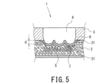
- FIG. 5 is a cross-sectional view showing a resin bonded body according to a modified example.
- FIG. 6 is a perspective view showing a test method of the embodiment.
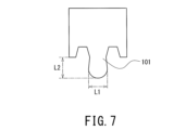
- FIG. 7 is a front view of the projection of the horn used in the embodiment.
- FIG. 8 is a cross-sectional view showing a test method of the embodiment.
- the resin bonded body according to the present embodiment may include a first resin member made of a foamed resin, a second resin member bonded to the first resin member, and a bonding portion bonding the first resin member and the second resin member.
- the bonding portion may include a molten hole penetrating the second resin member to form a recess in the first resin member, a concave bonding portion made of a non-foamed resin that contains the resin materials of the first and second resin members and is melted and solidified and formed on an inner wall of the recess, and an outer edge bonding portion that is continuous with the concave bonding portion and is formed between the first resin member and the second resin member.
- the resin material of the second resin member can easily flow into the recess during welding, allowing a proper concave joint to be formed. This increases the welding area and improves the joint strength.
- the concave joint portion may be formed continuously in a cross section including the central axis of the fusion hole. That is, the concave joint portion is formed without interruption on the inner wall of the recess. This can further improve the joining strength.
- the concave joint includes a curved surface that is tapered toward the bottom side of the recess at the interface with the first resin member. This allows the ultrasonic vibrations from the horn to be appropriately transmitted to the first and second resin members during spot welding to efficiently form a joint and improve the bonding strength.
- the concave joint portion may have a depth from the interface between the first resin member and the second resin member that is 20% to 75% of the thickness of the first resin member. This allows the concave joint portion to be appropriately formed and effectively improves the joining strength.
- the second resin member may be made of a non-foaming resin. This increases the amount of resin material flowing into the recess during spot welding, making it possible to effectively form the recessed joint.
- the second resin member may be made of a foamed resin. Even if the second resin member is made of a foamed resin, as long as the first resin member is made of a foamed resin, the resin material of the second resin member flows into the recesses during spot welding to form a concave joint, thereby improving the joining strength.
- the foaming ratio of the first resin member may be greater than 1 and not greater than 3. This makes it possible to suppress a decrease in the joining strength of the resin joined body.
- the first resin member may include a skin layer made of a non-foaming resin on a surface facing the second resin member.
- the melt hole may penetrate the skin layer to form a recess in the first resin member. This allows not only the second resin member but also the resin material of the skin layer to flow into the recess during spot welding, making the thickness of the concave joint larger. As a result, the joining strength can be further improved.
- the thickness of at least a part of the concave joint may be greater than the thickness of the skin layer. This allows the concave joint to have a greater thickness, improving the joining strength.
- the bond strength between the first resin member and the second resin member may be 0.6 kN or more. This allows the resin bonded body to obtain excellent bond strength.
- the resin bonded body 1 includes a resin member 2 (first resin member), a resin member 3 (second resin member), and a bonding portion 4.
- the resin member 2 is made of foamed resin.
- the resin member 2 is formed by foam molding. In other words, the resin member 2 has a large number of bubbles A.
- the thickness of the resin member 2 is not particularly limited, but is preferably 2 to 5 mm.
- the foamed resin is foamed by adding a chemical or physical foaming agent to molten resin.
- chemical foaming agents include ADCA (azodicarbonamide), DPT (N,N'-dinitropentamethylenetetramine), OBSH (4,4'-oxybisbenzenesulfonylhydrazide), hydrogen carbonates, or carbonates.
- Examples of physical foaming agents include nitrogen or carbon dioxide gas.
- the resin member 3 is made of a non-foaming resin.
- the non-foaming resin is molded without using a foaming agent as described above.
- the method for molding the non-foaming resin is not particularly limited, and may be an extrusion molding method or an injection molding method. In other words, the non-foaming resin is molded without adding a foaming agent to the molten resin, and does not contain bubbles formed by the foaming agent.
- the resin member 3 may be made of a foaming resin. However, as described later, the resin member 3 is preferably made of a non-foaming resin.
- the thickness of the resin member 3 is not particularly limited, but is preferably 2 to 5 mm.
- the resin material of the resin members 2 and 3 is a thermoplastic resin.
- the thermoplastic resin can be selected from various types, such as general-purpose plastics, engineering plastics, and super engineering plastics.
- the resin material of the resin members 2 and 3 is not particularly limited as long as it is a thermoplastic resin.
- polycarbonate resin which has excellent welding characteristics, acrylonitrile butadiene styrene (ABS) resin, acrylic (PMMA) resin, acrylic styrene (AS) resin, polyphenylene oxide resin, and combinations of these can be used.
- the joint 4 includes a molten hole 6 that penetrates the resin member 3 to form a recess 5 in the resin member 2, a concave joint 7 formed on the inner wall of the recess 5, and an outer edge joint 8 that is continuous with the concave joint 7 and is formed between the resin member 2 and the resin member 3.
- the melting hole 6 is formed in the spot welding method by, for example, applying pressure to the resin member 3 and the resin member 2 while ultrasonically vibrating a protrusion 101 of a horn 100 as shown in Figures 6 and 7. More specifically, with the resin member 2 and the resin member 3 superimposed, the ultrasonically vibrating protrusion 101 is pressed against the outer surface of the resin member 3 on the opposite side to the surface facing the resin member 2. In this embodiment, the protrusion 101 is pressed perpendicularly to the main surface of the resin member 2 that contacts the resin member 3. The protrusion 101 is inserted toward the resin member 2 while melting the resin member 3, penetrating the resin member 3 in the thickness direction.
- the protrusion 101 melts the resin member 2 and forms a recess 5 in the resin member 2, thereby forming the melting hole 6.
- the resin material of the resin member 3 and the resin material of the resin member 2 are melted and mixed and solidified, and a concave joint 7 and an outer edge joint 8 made of non-foamed resin are formed.
- the mechanism by which the concave joint 7 is formed is as follows.
- the resin member 2 is made of foamed resin containing a large number of bubbles A. Therefore, when the recess 5 is formed by the protrusion 101, the resin material of the resin member 2 melts and the volume of the resin member 2 is reduced by the volume of the large number of bubbles A.
- the resin material of the resin member 3 melted by the protrusion 101 flows into the recess 5, and the melted resin materials of the resin members 2 and 3 are mixed and cooled and solidified.
- the concave joint 7 is formed, which is made of non-foamed resin that contains the resin materials of the resin members 2 and 3 and is melted and solidified. Furthermore, the melted resin material of the resin members 2 and 3 flows into the interface between the resin members 2 and 3, and an outer edge joint 8 that is continuous with the outer edge of the concave joint 7 is formed.
- the outer edge joint 8 is formed so as to extend continuously from the outer edge of the opening end of the concave joint 7 at the interface between the resin member 2 and the resin member 3. Therefore, the outer edge joint 8 is formed in a ring shape in a plan view when viewed from the outer surface of the resin member 3.
- the boundary B between the concave joint 7 and the outer edge joint 8 can be defined as follows. With reference to FIG. 2, in a vertical cross-sectional view including the central axis CL, the boundary B is formed by a virtual line that is parallel to the central axis CL and passes through the lower end point C when the lower end of the inner peripheral surface of the resin member 3 facing the molten hole 6 is the lower end point C.
- the concave joint 7 is a region closer to the central axis CL than the boundary B (a region on the central axis CL side), and the outer edge joint 8 is a region farther from the central axis CL than the boundary B (a region on the opposite side to the central axis CL).
- the contact point D in the figure is the contact point between the virtual line forming the boundary B and the inner wall of the recess 5 formed in the resin member 2.
- the joining strength of the resin joined body 1 can be, for example, 0.6 kN or more, and excellent joining strength can be obtained.
- the concave joint 7 is formed to cover the inner wall of the recess 5. Therefore, the concave joint 7 is formed along the shape of the recess 5.
- the concave joint 7 may be formed into a bowl shape, a mortar shape, or a bowl shape according to the shape of the protrusion 101 shown in FIG. 7.
- the symbol L1 shown in FIG. 7 indicates the diameter of the protrusion 101, and the symbol L2 indicates the protruding width of the protrusion 101.
- the shape of the concave joint 7 can be changed in various ways according to the shape of the protrusion 101 of the horn 100, and may be formed into an inverted polygonal pyramid shape such as an inverted triangular pyramid (V-shaped in cross section) or an inverted square pyramid, an inverted polygonal pyramid truncated shape such as an inverted triangular pyramid truncated or an inverted square pyramid truncated, a U-shaped cross section such as a hemispherical shape or a semi-elliptical spherical shape, or a W-shaped cross section in which inverted triangular pyramid shapes are arranged.
- V-shaped in cross section V-shaped in cross section
- an inverted square pyramid an inverted polygonal pyramid truncated shape such as an inverted triangular pyramid truncated or an inverted square pyramid truncated
- a U-shaped cross section such as a hemispherical shape or a semi-elliptical spher
- the shape of the protrusion 101 should preferably include a semispherical shape
- the shape of the concave joint 7 should preferably be a bowl shape, a mortar shape, or a bowl shape. That is, the concave joint 7 includes a curved surface 9 tapered toward the bottom side of the recess 5 at the interface with the resin member 2, so that it comes into point contact with the outer surface of the resin member 3, and the joint 4 can be efficiently formed in the joining process of the resin member 2 and the resin member 3, and the joining strength can be improved.
- the concave joint 7 is formed continuously in a cross section including the central axis CL of the fusion hole 6.
- the concave joint 7 is formed continuously with a predetermined thickness, and can cover the surface of the recess 5 without interruption.
- the concave joint 7 may cover the entire surface of the inner wall of the recess 5. This can improve the joining strength of the resin joint 1.
- the thickness of the concave joint 7 can be gradually increased toward the bottom side of the recess.
- the resin material of the molten resin members 2 and 3 flows into the recess 5 in response to the reduction in the volume of the air bubbles A.
- the molten resin material tends to flow toward the bottom side of the recess 5 due to gravity.
- the concave joint 7 may have the greatest thickness at the deepest position of the recess 5, which in this embodiment is a position passing through the central axis CL of the molten hole 6. This allows the thickness of the concave joint 7 to be increased at the bottom side of the recess 5, improving the joining strength of the resin joint 1.
- the thickness t3 of the concave joint 7 in the direction along the normal to the contact point D shown in FIG. 2 is not larger than the thickness t4 in the direction along the central axis CL at the bottom end located at the deepest position of the concave joint 7 in the cross section including the central axis CL (t3 ⁇ t4).
- the boundary B is formed in a frame shape in a plan view (annular if the shape of the protrusion 101 in a plan view is circular). Therefore, it is sufficient that the thickness t3 is not larger than the thickness t4 at least in a part of the frame-shaped boundary.
- the bottom end is considered to be located near a part of the concave joint 7 through which the central axis CL passes.
- the bottom end is formed at one of the multiple lower ends of the concave joint 7 formed in one of the multiple recesses 5 among the corrugated concave joints 7. This makes it possible to increase the thickness of the concave joint 7 at the bottom side of the recess 5, thereby improving the bonding strength of the resin joint 1.
- the concave joint 7 may have a depth d of 20% to 75% from the interface between the resin member 2 and the resin member 3 with respect to the thickness T of the resin member 2 made of foamed resin. If the depth d is too small, the resin material of the molten resin member 3 does not easily flow into the recess 5, and the concave joint 7 is formed discontinuously, which may reduce the effect of improving the joint strength. On the other hand, if the depth d is too large, the thickness of the resin member 2 at the position where the recess 5 is formed becomes small, which may reduce the effect of improving the joint strength.
- the depth d is preferably 20% or more, preferably 30% or more, and 75% or less, preferably 50% or less, with respect to the thickness of the resin member 2. Also, if the depth d is too large, i.e., the recess 5 is too deep, a convex bulge may be formed on the back side (lower in the figure) of the resin member 2, i.e., on the outer surface of the resin member 2 opposite the surface facing the resin member 3, depending on the formation of the recess 5. Therefore, from the perspective of suppressing the occurrence of this convex bulge and improving the appearance design, the depth d should be 75% or less, and preferably 50% or less, of the thickness of the resin member 2.
- the resin member 3 may be made of a foamed resin. That is, when the resin member 3 is made of a foamed resin and the resin member 2 is made of a foamed resin, the resin material of the molten resin members 2 and 3 flows into the recess 5 in response to the volume reduction when the resin member 2 melts, and the concave joint 7 can be formed.
- the resin member 3 is made of a non-foamed resin, the amount of resin material flowing into the recess 5 can be increased compared to when the resin member 3 is made of a foamed resin. Therefore, from the viewpoint of more effectively forming the concave joint 7, it is preferable that the resin material is made of a non-foamed resin.
- the density of the resin member 3 is not greater than the density of the resin member 2.
- the densities of the resin members 2 and 3 are measured by an underwater displacement method in accordance with JIS K7112.
- the foaming ratio of the resin member 2 can be greater than 1 and less than 3.
- the foaming ratio of the resin member 2 is more preferably 1.5 to 2.
- the expansion ratio can be calculated by dividing the specific gravity of the unfoamed (solid) resin before foaming by the specific gravity of the foamed resin after foaming. If the expansion ratio of the resin member 2 is greater than 3, the strength of the resin member 2 itself decreases, and the bonding strength after welding with the resin member 3 may also decrease.
- the expansion ratio of the resin member 2 is 1 or less (unfoamed)
- the resin material of the resin member 3 does not easily flow into the recess 5 during welding, making it difficult to obtain sufficient bonding strength. Therefore, by setting the expansion ratio of the resin member 2 to be greater than 1 and less than 3, it is possible to suppress a decrease in the bonding strength of the resin joined body 1.
- the resin bonded body 1 may have a plurality of bonding portions 4.
- a resin member 3 which is a structure such as a rib or a boss
- the bonding flange surface 31 is rectangular in plan view
- the bonding flange surface 31 is annular, such as a circular ring or an elliptical ring, in plan view, it is preferable to provide the bonding portions 4 at four or more locations at equal angles.
- each bonding portion 4 is provided at every 90° in plan view. Furthermore, when the area of the bonding flange surface in plan view is relatively large, 1 m 2 or more, from the viewpoint of ensuring the bonding strength of the resin member 2 and the resin member 3, the interval between each of the plurality of bonding portions 4 is 200 mm or less, preferably 150 mm or less. On the other hand, if the interval between the bonding portions 4 is too small, the number of bonding steps increases and production efficiency decreases. Therefore, the interval between each of the plurality of joints 4 should be 20 mm or more, and preferably 50 mm or more.
- the resin member 2 has a skin layer 21 on the surface facing the resin member 3.
- the skin layer 21 is made of a non-foamed resin. Therefore, it can be said that the resin member 2 includes a core layer made of a foamed resin and a skin layer 21 made of a non-foamed resin.
- the resin member 2 having the skin layer 21 can be formed by a molding method such as co-extrusion molding or injection molding. For example, in the co-extrusion molding method, the resin member 2 including the skin layer 21 is extruded while foaming it using a foaming agent, and a non-foamed resin is separately extruded, and the non-foamed resin that becomes the skin layer 21 is merged with the surface of the resin member 2. In this way, the resin member 2 having the skin layer 21 can be molded.
- the skin layer 21 may be provided on the outer surface of the resin member 2 opposite to the surface facing the resin member 3.
- the melt hole 6 penetrates the skin layer 21 to form a recess 5 in the resin member 2.
- the depth d in the second embodiment is to be interpreted as the depth d including the skin layer 21.
- the depth d in the second embodiment is the depth of the recess 5 from the interface between the resin member 3 and the skin layer 21 facing the resin member 3.
- the concave joint 7 is formed during the process of forming the joint 4, containing not only the resin member 3 made of non-foamed resin but also the resin material of the skin layer 21.
- the concave joint 7 can be said to be a non-foamed resin layer that contains the resin material of the resin member 3 and the resin material of the resin member 2 including the skin layer 21, and is cooled and solidified.
- the skin layer 21 is made of non-foamed resin. Therefore, more resin material can be poured into the recess 5 than in the joint 4 of the first embodiment, and a concave joint 7 that is effectively thicker can be formed. This can further improve the joint strength.
- the thickness t1 of at least a part of the concave joint 7 is greater than the thickness t2 of the skin layer 21.
- the thickness t1 of the concave joint 7 is the thickness along the normal to the inside of the concave joint 7, i.e., the curved surface on the side of the fusion hole 6.
- the thickness t1 of the concave joint 7 is the thickness along the direction perpendicular to the inner surface of the concave joint 7. As shown in FIG.
- the thickness t1 of the concave joint 7 passing through at least the central axis CL of the fusion hole 6 is greater than the thickness t2 of the skin layer 21.
- the thickness t1 of the concave joint 7 is greater than the thickness t2 of the skin layer 21, it can be said that a thicker concave joint 7 can be efficiently formed. Therefore, if the thickness t1 of the concave joint 7 can be formed greater than the thickness t2 of the skin layer 21, the joining strength can be improved more effectively.
- a plurality of recesses 5 may be formed.
- a corrugated concave joint 7 may be formed together with the plurality of recesses 5. This increases the area of the joint interface between the concave joint 7 and the resin member 2 compared to when one recess 5 is formed, so that good joint strength can be obtained even if the depth d of the concave joint 7 is relatively small.
- Such a plurality of recesses 5 and the corrugated concave joint 7 can be formed, for example, by a horn 100 having a plurality of protrusions 101 at its tip.
- a convex bulge may be formed on the outer surface of the resin member 2 opposite to the surface facing the resin member 3 in response to the formation of the recesses 5.
- the depth d of the concave joint 7 By making the depth d of the concave joint 7 smaller, the occurrence of a convex bulge can be suppressed, which contributes to improving the appearance of the resin joined body 1. This is also true for the resin joined body 1 of the first embodiment.
- the resin member 2 and the resin member 3 may also be welded by pressing a heating element such as a soldering iron from the outer surface of the resin member 3 toward the resin member 2.
- a heating element such as a soldering iron
- the method of joining the resin member 2 and the resin member 3 is not limited to the ultrasonic welding method described above, and is not particularly limited as long as the resin member 2 and the resin member 3 can be melted while being pressed to form the joint 4.
- Products and parts made with the resin bonded body 1 can reduce the amount of resin used.
- the resin bonded body 1 of this embodiment can contribute to improving resource utilization efficiency, reducing the burden of transportation, reducing energy consumption, and reducing CO2 emissions.
- Goal 7 Affordable and Clean Energy
- Goal 9 Industry, Innovation and Infrastructure
- Goal 11 Sestainable Cities and Communities
- Test piece 1 is a resin bonded body of a resin member 2 and a resin member 3, each of which includes a skin layer on both main surfaces as shown in FIG. 4.
- the resin member 2 has a thickness of 2 mm and was produced in a sheet shape by a co-extrusion foam molding method. The thickness of each skin layer was 0.2 mm.
- the resin member 3 has a thickness of 2 mm and was produced in a sheet shape by an injection molding method.
- the resin material of the resin members 2 and 3 was polycarbonate resin.
- the density of the resin member 2 was 0.65 g/ cm3
- the density of the resin member 3 was 1.2 g/ cm3 .
- the ultrasonic welding conditions were as follows: trigger load: 50 N, frequency: 28.5 Hz, amplitude: 100%, pressure applied: 0.4 MPa, holding time during welding: 0.2 s, actual measured value of sinking amount of the welding horn 100 from detection of the trigger load to completion of welding: 2.3 mm.
- the bonding strength of specimen 1 was evaluated by a tensile test. As shown in Figure 8, the specimen was pulled in the direction along the interface between resin member 2 and resin member 3 at a test speed of 50 mm/min, and the maximum load at which the bonding interface was pulled apart was measured.
- the bond strength of specimen 1 was the highest, at 1.11 kN.
- the bond strength of specimen 2 was 0.89 kN, and the bond strength of specimen 3 was 0.79 kN.
- the bond strengths of specimens 4 and 5 were lower than those of specimens 1, 2, and 3. When the bond interfaces of specimens 1 to 3 were observed after the tensile test, the resin was found to have been torn from the inside at the concave bond portion. Meanwhile, specimens 4 and 5 showed signs of destruction at the outer edge bond portions.
- specimens 1 to 5 were cut with a microtome, and the cross sections of the concave joints were observed under a microscope.
- specimens 1 to 3 as shown in Figures 2 and 4, it was possible to confirm the concave joints and the outer edge joints formed continuously from the concave joints.
- specimens 4 and 5 it was not possible to confirm the concave joints, and only the outer edge joints could be confirmed.
- resin member 3 is made of a non-foamed resin and resin member 2 has a skin layer, which increases the amount of resin material flowing into the recess and makes the thickness of the concave joint relatively large. This is thought to increase the resin strength at the joint interface and improve the joint strength. Also, in specimen 3, when the density of resin member 3 is greater than the density of resin member 2, a greater amount of resin flows into the recess, which is thought to increase the joint strength.
- the resin member 2 is made of a non-foaming resin, so the resin material of the molten resin member 3 overflows from the open end of the melting hole to the outside, making it difficult for the resin material of the resin member 3 to flow into the recess. As a result, the welding area is smaller and the joint strength is also lower.
- polycarbonate resin which is an amorphous resin
- ABS acrylonitrile butadiene styrene
- PMMA acrylic
- AS acrylic styrene
- polyphenylene oxide resin polyphenylene oxide resin
Landscapes
- Engineering & Computer Science (AREA)
- Mechanical Engineering (AREA)
- Lining Or Joining Of Plastics Or The Like (AREA)
Priority Applications (2)
| Application Number | Priority Date | Filing Date | Title |
|---|---|---|---|
| JP2025503595A JPWO2024180868A1 (https=) | 2023-02-28 | 2023-12-14 | |
| CN202380095045.9A CN120813467A (zh) | 2023-02-28 | 2023-12-14 | 树脂接合体 |
Applications Claiming Priority (2)
| Application Number | Priority Date | Filing Date | Title |
|---|---|---|---|
| JP2023029221 | 2023-02-28 | ||
| JP2023-029221 | 2023-02-28 |
Publications (1)
| Publication Number | Publication Date |
|---|---|
| WO2024180868A1 true WO2024180868A1 (ja) | 2024-09-06 |
Family
ID=92589521
Family Applications (1)
| Application Number | Title | Priority Date | Filing Date |
|---|---|---|---|
| PCT/JP2023/044817 Ceased WO2024180868A1 (ja) | 2023-02-28 | 2023-12-14 | 樹脂接合体 |
Country Status (3)
| Country | Link |
|---|---|
| JP (1) | JPWO2024180868A1 (https=) |
| CN (1) | CN120813467A (https=) |
| WO (1) | WO2024180868A1 (https=) |
Citations (4)
| Publication number | Priority date | Publication date | Assignee | Title |
|---|---|---|---|---|
| JP2018519185A (ja) * | 2015-06-11 | 2018-07-19 | ウッドウェルディング・アクチェンゲゼルシャフト | 軽量建造物要素における固定 |
| US20190126562A1 (en) * | 2016-03-21 | 2019-05-02 | Multimaterial-Welding Ag | Securing a second object to a first object |
| WO2021193828A1 (ja) * | 2020-03-25 | 2021-09-30 | 古河電気工業株式会社 | 接合構造、接合方法、ワイヤーハーネス用外装体およびワイヤーハーネス |
| US20220410496A1 (en) * | 2019-11-29 | 2022-12-29 | Multimaterial-Welding Ag | Securing a second object to a first object |
-
2023
- 2023-12-14 JP JP2025503595A patent/JPWO2024180868A1/ja active Pending
- 2023-12-14 CN CN202380095045.9A patent/CN120813467A/zh active Pending
- 2023-12-14 WO PCT/JP2023/044817 patent/WO2024180868A1/ja not_active Ceased
Patent Citations (4)
| Publication number | Priority date | Publication date | Assignee | Title |
|---|---|---|---|---|
| JP2018519185A (ja) * | 2015-06-11 | 2018-07-19 | ウッドウェルディング・アクチェンゲゼルシャフト | 軽量建造物要素における固定 |
| US20190126562A1 (en) * | 2016-03-21 | 2019-05-02 | Multimaterial-Welding Ag | Securing a second object to a first object |
| US20220410496A1 (en) * | 2019-11-29 | 2022-12-29 | Multimaterial-Welding Ag | Securing a second object to a first object |
| WO2021193828A1 (ja) * | 2020-03-25 | 2021-09-30 | 古河電気工業株式会社 | 接合構造、接合方法、ワイヤーハーネス用外装体およびワイヤーハーネス |
Also Published As
| Publication number | Publication date |
|---|---|
| JPWO2024180868A1 (https=) | 2024-09-06 |
| CN120813467A (zh) | 2025-10-17 |
Similar Documents
| Publication | Publication Date | Title |
|---|---|---|
| EP1240002B1 (en) | Frictionally welded thermoplastic article and method for welding two thermoplastic workpieces | |
| EP2202050B1 (en) | Method of anchoring a connector, and connector | |
| WO2017169350A1 (ja) | 発泡複合成形体、および発泡複合成形体の製造方法 | |
| WO2024180868A1 (ja) | 樹脂接合体 | |
| JP7717679B2 (ja) | 接合構造、接合方法、ワイヤーハーネス用外装体およびワイヤーハーネス | |
| JP2011218583A (ja) | 超音波接合方法及びこの方法によって接合された接合体 | |
| JP4784811B2 (ja) | ゴム・樹脂の超音波接合方法 | |
| JP2007038422A (ja) | 樹脂部品の超音波溶着方法 | |
| JP4066071B2 (ja) | 合成樹脂製中空体とその製造方法及びその金型 | |
| JPH06270258A (ja) | 熱可塑性樹脂容器の製造方法 | |
| JP5547397B2 (ja) | 射出成形装置、射出成形体およびその製造方法 | |
| JP2006001136A (ja) | プラスチックダンボールの加工装置およびプラスチックダンボールの加工方法 | |
| JP2008238437A (ja) | 容器の製造方法 | |
| JP2003137205A (ja) | 超音波溶着工法及びトナーケース | |
| WO2017141936A1 (ja) | 発泡構造体、樹脂製パネル | |
| JP4693829B2 (ja) | 樹脂板の接合方法 | |
| CN211607078U (zh) | 一种电源 | |
| JP4509648B2 (ja) | 摩擦撹拌接合方法 | |
| JP2026057786A (ja) | 自動車用樹脂部品の製造方法及び超音波溶着ホーン | |
| JPH11268135A (ja) | 超音波接合方法 | |
| JP2024113385A (ja) | 蓋付き発泡容器及び発泡容器 | |
| JP7549828B2 (ja) | 二重容器及び二重容器の接合方法 | |
| JP2025126570A (ja) | 超音波溶着方法 | |
| JP2938113B2 (ja) | ブリスターパックの製造方法 | |
| JP4781002B2 (ja) | プラスチック製天井材 |
Legal Events
| Date | Code | Title | Description |
|---|---|---|---|
| 121 | Ep: the epo has been informed by wipo that ep was designated in this application |
Ref document number: 23925419 Country of ref document: EP Kind code of ref document: A1 |
|
| WWE | Wipo information: entry into national phase |
Ref document number: 2025503595 Country of ref document: JP |
|
| WWE | Wipo information: entry into national phase |
Ref document number: 202380095045.9 Country of ref document: CN |
|
| NENP | Non-entry into the national phase |
Ref country code: DE |
|
| WWP | Wipo information: published in national office |
Ref document number: 202380095045.9 Country of ref document: CN |
|
| 122 | Ep: pct application non-entry in european phase |
Ref document number: 23925419 Country of ref document: EP Kind code of ref document: A1 |