WO2024180652A1 - 物体検知装置及び物体検知方法 - Google Patents
物体検知装置及び物体検知方法 Download PDFInfo
- Publication number
- WO2024180652A1 WO2024180652A1 PCT/JP2023/007257 JP2023007257W WO2024180652A1 WO 2024180652 A1 WO2024180652 A1 WO 2024180652A1 JP 2023007257 W JP2023007257 W JP 2023007257W WO 2024180652 A1 WO2024180652 A1 WO 2024180652A1
- Authority
- WO
- WIPO (PCT)
- Prior art keywords
- reliability
- vehicle
- detection device
- detection
- speed
- Prior art date
- Legal status (The legal status is an assumption and is not a legal conclusion. Google has not performed a legal analysis and makes no representation as to the accuracy of the status listed.)
- Ceased
Links
Images





Classifications
-
- G—PHYSICS
- G01—MEASURING; TESTING
- G01S—RADIO DIRECTION-FINDING; RADIO NAVIGATION; DETERMINING DISTANCE OR VELOCITY BY USE OF RADIO WAVES; LOCATING OR PRESENCE-DETECTING BY USE OF THE REFLECTION OR RERADIATION OF RADIO WAVES; ANALOGOUS ARRANGEMENTS USING OTHER WAVES
- G01S13/00—Systems using the reflection or reradiation of radio waves, e.g. radar systems; Analogous systems using reflection or reradiation of waves whose nature or wavelength is irrelevant or unspecified
- G01S13/88—Radar or analogous systems specially adapted for specific applications
- G01S13/93—Radar or analogous systems specially adapted for specific applications for anti-collision purposes
- G01S13/931—Radar or analogous systems specially adapted for specific applications for anti-collision purposes of land vehicles
-
- B—PERFORMING OPERATIONS; TRANSPORTING
- B60—VEHICLES IN GENERAL
- B60W—CONJOINT CONTROL OF VEHICLE SUB-UNITS OF DIFFERENT TYPE OR DIFFERENT FUNCTION; CONTROL SYSTEMS SPECIALLY ADAPTED FOR HYBRID VEHICLES; ROAD VEHICLE DRIVE CONTROL SYSTEMS FOR PURPOSES NOT RELATED TO THE CONTROL OF A PARTICULAR SUB-UNIT
- B60W30/00—Purposes of road vehicle drive control systems not related to the control of a particular sub-unit, e.g. of systems using conjoint control of vehicle sub-units
- B60W30/08—Active safety systems predicting or avoiding probable or impending collision or attempting to minimise its consequences
-
- G—PHYSICS
- G01—MEASURING; TESTING
- G01S—RADIO DIRECTION-FINDING; RADIO NAVIGATION; DETERMINING DISTANCE OR VELOCITY BY USE OF RADIO WAVES; LOCATING OR PRESENCE-DETECTING BY USE OF THE REFLECTION OR RERADIATION OF RADIO WAVES; ANALOGOUS ARRANGEMENTS USING OTHER WAVES
- G01S13/00—Systems using the reflection or reradiation of radio waves, e.g. radar systems; Analogous systems using reflection or reradiation of waves whose nature or wavelength is irrelevant or unspecified
- G01S13/02—Systems using reflection of radio waves, e.g. primary radar systems; Analogous systems
- G01S13/06—Systems determining position data of a target
- G01S13/42—Simultaneous measurement of distance and other co-ordinates
-
- G—PHYSICS
- G01—MEASURING; TESTING
- G01S—RADIO DIRECTION-FINDING; RADIO NAVIGATION; DETERMINING DISTANCE OR VELOCITY BY USE OF RADIO WAVES; LOCATING OR PRESENCE-DETECTING BY USE OF THE REFLECTION OR RERADIATION OF RADIO WAVES; ANALOGOUS ARRANGEMENTS USING OTHER WAVES
- G01S13/00—Systems using the reflection or reradiation of radio waves, e.g. radar systems; Analogous systems using reflection or reradiation of waves whose nature or wavelength is irrelevant or unspecified
- G01S13/02—Systems using reflection of radio waves, e.g. primary radar systems; Analogous systems
- G01S13/50—Systems of measurement based on relative movement of target
- G01S13/58—Velocity or trajectory determination systems; Sense-of-movement determination systems
- G01S13/589—Velocity or trajectory determination systems; Sense-of-movement determination systems measuring the velocity vector
-
- G—PHYSICS
- G01—MEASURING; TESTING
- G01S—RADIO DIRECTION-FINDING; RADIO NAVIGATION; DETERMINING DISTANCE OR VELOCITY BY USE OF RADIO WAVES; LOCATING OR PRESENCE-DETECTING BY USE OF THE REFLECTION OR RERADIATION OF RADIO WAVES; ANALOGOUS ARRANGEMENTS USING OTHER WAVES
- G01S7/00—Details of systems according to groups G01S13/00, G01S15/00, G01S17/00
- G01S7/02—Details of systems according to groups G01S13/00, G01S15/00, G01S17/00 of systems according to group G01S13/00
- G01S7/41—Details of systems according to groups G01S13/00, G01S15/00, G01S17/00 of systems according to group G01S13/00 using analysis of echo signal for target characterisation; Target signature; Target cross-section
- G01S7/414—Discriminating targets with respect to background clutter
-
- G—PHYSICS
- G01—MEASURING; TESTING
- G01S—RADIO DIRECTION-FINDING; RADIO NAVIGATION; DETERMINING DISTANCE OR VELOCITY BY USE OF RADIO WAVES; LOCATING OR PRESENCE-DETECTING BY USE OF THE REFLECTION OR RERADIATION OF RADIO WAVES; ANALOGOUS ARRANGEMENTS USING OTHER WAVES
- G01S7/00—Details of systems according to groups G01S13/00, G01S15/00, G01S17/00
- G01S7/02—Details of systems according to groups G01S13/00, G01S15/00, G01S17/00 of systems according to group G01S13/00
- G01S7/41—Details of systems according to groups G01S13/00, G01S15/00, G01S17/00 of systems according to group G01S13/00 using analysis of echo signal for target characterisation; Target signature; Target cross-section
- G01S7/415—Identification of targets based on measurements of movement associated with the target
-
- G—PHYSICS
- G08—SIGNALLING
- G08G—TRAFFIC CONTROL SYSTEMS
- G08G1/00—Traffic control systems for road vehicles
- G08G1/16—Anti-collision systems
- G08G1/165—Anti-collision systems for passive traffic, e.g. including static obstacles, trees
-
- G—PHYSICS
- G08—SIGNALLING
- G08G—TRAFFIC CONTROL SYSTEMS
- G08G1/00—Traffic control systems for road vehicles
- G08G1/16—Anti-collision systems
- G08G1/166—Anti-collision systems for active traffic, e.g. moving vehicles, pedestrians, bikes
-
- G—PHYSICS
- G01—MEASURING; TESTING
- G01S—RADIO DIRECTION-FINDING; RADIO NAVIGATION; DETERMINING DISTANCE OR VELOCITY BY USE OF RADIO WAVES; LOCATING OR PRESENCE-DETECTING BY USE OF THE REFLECTION OR RERADIATION OF RADIO WAVES; ANALOGOUS ARRANGEMENTS USING OTHER WAVES
- G01S13/00—Systems using the reflection or reradiation of radio waves, e.g. radar systems; Analogous systems using reflection or reradiation of waves whose nature or wavelength is irrelevant or unspecified
- G01S13/86—Combinations of radar systems with non-radar systems, e.g. sonar, direction finder
-
- G—PHYSICS
- G01—MEASURING; TESTING
- G01S—RADIO DIRECTION-FINDING; RADIO NAVIGATION; DETERMINING DISTANCE OR VELOCITY BY USE OF RADIO WAVES; LOCATING OR PRESENCE-DETECTING BY USE OF THE REFLECTION OR RERADIATION OF RADIO WAVES; ANALOGOUS ARRANGEMENTS USING OTHER WAVES
- G01S13/00—Systems using the reflection or reradiation of radio waves, e.g. radar systems; Analogous systems using reflection or reradiation of waves whose nature or wavelength is irrelevant or unspecified
- G01S13/88—Radar or analogous systems specially adapted for specific applications
- G01S13/93—Radar or analogous systems specially adapted for specific applications for anti-collision purposes
- G01S13/931—Radar or analogous systems specially adapted for specific applications for anti-collision purposes of land vehicles
- G01S2013/932—Radar or analogous systems specially adapted for specific applications for anti-collision purposes of land vehicles using own vehicle data, e.g. ground speed, steering wheel direction
Definitions
- the present invention relates to an object detection device and an object detection method that can distinguish between stationary and moving objects, even in situations where the angular accuracy is degraded.
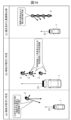
- UNR159 is mandatory because it is applied as a law in each country. Among them, UNR159 requires an alarm output even when the vehicle and the alarm target are stopped (both ground speed and relative speed are 0km/h). Conventionally, false detection and false alarms were suppressed by not recognizing stationary objects as objects (see (a) in Figure 1), but the addition of the above-mentioned law has made it mandatory to detect stationary objects. For example, radar has high accuracy in distance and speed in the line of sight direction, but cannot measure speed in the circumferential direction, and its angular accuracy is poor compared to its distance accuracy.
- Patent Document 1 is known as a conventional technique for determining whether an object with a line-of-sight velocity of 0 m/s is a stationary object (wall) or a moving object.
- Patent Document 1 when a wall is present on the side of the vehicle while it is moving and the wall is mistakenly determined to be a moving object, the movement history is compared with the current detection point to determine whether it is a wall or an object moving alongside.
- Patent Document 1 is based on the assumption that detection points occur in addition to the target, and cannot be applied to cases where only one detection point is output for an object. In a situation where multiple stationary objects are equidistant and only one detection point is detected, a large angle error occurs, and there is a risk that the stationary object will be determined to be a moving object that moves back and forth from side to side.
- the present invention was made in consideration of the above problems, and aims to provide an object detection device and method that can determine that an object is stationary even in a situation where an object would be determined to be moving back and forth due to an angle error, for example.
- the object detection device includes a ground speed acquisition unit that acquires the relative position and relative speed between the vehicle and a detection object around the vehicle detected by an object recognition sensor mounted on the vehicle, and acquires the ground speed of the detection object based on the relative position, the relative speed, the speed of the vehicle, and the yaw rate of the vehicle; and a determination unit that acquires a first direction reliability that is an index showing the movement of the detection object in a predetermined first direction based on the ground speed, acquires a second direction reliability that is an index showing the movement of the detection object in a second direction that is opposite to the first direction based on the ground speed, and determines whether the detection object is a stationary object or a moving object based on the first direction reliability and the second direction reliability.
- the object detection method is an object detection method executed by a control unit mounted on a vehicle, in which the control unit acquires the relative position and relative speed between the vehicle and a detection object around the vehicle detected by an object recognition sensor mounted on the vehicle, acquires the ground speed of the detection object based on the relative position, the relative speed, the speed of the vehicle, and the yaw rate of the vehicle, acquires a first directional reliability that is an index showing the movement of the detection object in a predetermined first direction based on the ground speed, acquires a second directional reliability that is an index showing the movement of the detection object in a second direction that is opposite to the first direction based on the ground speed, and determines whether the detection object is a stationary object or a moving object based on the first directional reliability and the second directional reliability.
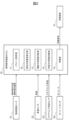
- FIG. 2 illustrates an example of a system configuration of an object detection device according to the first embodiment.
- 5 is a flowchart of a line-of-sight direction movement determining unit 13 in the first embodiment.
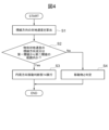
- 5 is a flowchart of a circumferential direction movement determining unit 14 in the first embodiment.
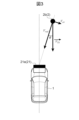
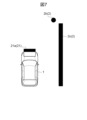
- FIG. 2 is an explanatory diagram of a simulation environment according to the first embodiment. Parameters used in the simulation (conventional method). Parameters used in the simulation (Example 1).
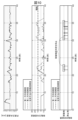
- FIG. 1 is an explanatory diagram of the results of a simulation.
- FIG. 11 is an explanatory diagram of the concept of error caused by a monocular camera in the second embodiment.
- 10 is a flowchart of a circumferential direction movement determining unit 14 in the second embodiment.
- 13 is a flowchart of the line of sight direction movement determination unit 13 in the second embodiment.
- FIG. 13 is an explanatory diagram of factors that are not applied during high-speed driving in the third embodiment.
- Example 1 a vehicle control device 10 which is an object detection device according to a first embodiment of the present invention will be described with reference to Figs.
- FIG. 2 is a functional block diagram of the driving assistance system installed in the vehicle 1 of this embodiment.
- This driving assistance system is a system in which an object recognition sensor 21, a vehicle speed sensor 22, a steering angle sensor 23, and a yaw rate sensor 24 are present on the input side of the vehicle control device 10, and an alarm device 31 is present on the output side.
- an object recognition sensor 21, a vehicle speed sensor 22, a steering angle sensor 23, and a yaw rate sensor 24 are present on the input side of the vehicle control device 10, and an alarm device 31 is present on the output side.
- CAN controller area network
- the object recognition sensor 21 is a sensor that acquires information about objects 2 (e.g., moving objects 2a such as other vehicles and pedestrians) around the vehicle 1, and is, for example, a radar 21a, a monocular camera 21b, etc. If the object recognition sensor 21 is a monocular camera 21b, it can sequentially measure the relative position PTR ( xTR , yTR ) of the object 2 from each piece of photographed data, and calculate the relative speed VTR of the object 2 from the displacement of the object 2 in each piece of photographed data. Also, if the object recognition sensor 21 is a radar 21a or the like, it can directly measure the relative position and relative speed of the object 2.
- objects 2 e.g., moving objects 2a such as other vehicles and pedestrians
- control content will be described when the object recognition sensor 21 is a radar 21a.
- the vehicle speed sensor 22 is a sensor that detects the host vehicle speed V S and calculates the host vehicle speed V S on the assumption that the host vehicle 1 is traveling straight based on the tire rotation speed output by a wheel speed sensor, for example.
- the steering angle sensor 23 is a sensor that acquires the steering angle (amount) of the vehicle 1, and is, for example, an angle sensor attached to the steering wheel.
- the yaw rate sensor 24 is a sensor that acquires the yaw rate ⁇ of the vehicle 1, and is, for example, an acceleration sensor that detects the acceleration around the vertical axis of the vehicle 1. Note that the yaw rate ⁇ can also be calculated using the vehicle speed sensor 22 and the steering angle sensor 23, so the yaw rate sensor 24 may be omitted.
- the warning device 31 is a device that warns the driver of the possibility of a collision with the object 2 via a display, LED illumination, steering operation, audio notification, etc., when the vehicle control device 10 outputs a warning request, and prompts the driver to take appropriate avoidance action. Note that in FIG. 2, the driver is prompted to take avoidance action via the warning device 31, but the system may also be such that the vehicle control device 10 directly controls the braking and steering of the vehicle 1 when there is a possibility of a collision.
- the vehicle control device 10 which is an object detection device, includes a parameter storage unit 11, an object ground speed calculation unit 12, a line of sight direction movement determination unit 13, a circumferential direction movement determination unit 14, and an alarm unit 15.
- the object ground speed calculation unit 12, the line of sight direction movement determination unit 13, the circumferential direction movement determination unit 14, and the alarm unit 15 periodically execute processes, and when a predetermined condition is satisfied, an alarm request is created and output to the alarm device 31.
- the vehicle control device 10 is specifically an ECU (Electronic Control Unit) equipped with a calculation device such as a CPU, a storage device such as a semiconductor memory, and hardware such as a communication device.
- the calculation device executes a program loaded into the storage device to realize each function of the line of sight direction movement determination unit 13, etc., but the following description will be given while appropriately omitting such well-known techniques.
- the parameter storage unit 11 is a storage device that stores vehicle parameters and warning parameters.
- vehicle parameters are parameters that are mainly used by the circumferential movement determination unit 14, and are parameters related to the specifications of the vehicle 1, such as the circumferential movement threshold, reliability threshold, wheel base, and gear ratio that converts steering angle to tire angle.
- warning parameters are parameters that are mainly used by the warning unit 15, and are parameters such as the Time To Collision (TTC) threshold for comparison with the time to collision of warning candidates.
- TTC Time To Collision
- the object ground speed calculation unit 12 can obtain the ground speed from the speed of the vehicle 1 and the object relative speed of the object recognition sensor 21.
- the method of calculating the ground speed is not particularly limited, and any known ground speed calculation method can be used.
- the relative speed can be calculated using the object relative position of the object recognition sensor 21, and the ground speed can be calculated by combining this with the vehicle information described above (vehicle speed and yaw rate of the vehicle 1).
- the line of sight direction movement determination unit 13 may be implemented together with the circumferential direction movement determination unit 14. In the first embodiment, the processing of the line of sight direction movement determination unit using the radar 21a will be described. In the second embodiment described later, the processing of the line of sight direction movement determination unit using the monocular camera 21b will be described. In the third embodiment, the reason for using the conventional stationary object determination result when driving at high speed will be described.
- the processing of the circumferential direction movement determination unit using the radar 21a will be described.
- the processing of the circumferential direction movement determination unit using the monocular camera 21b will be described.
- the reason for using the conventional stationary object determination result when traveling at high speed will be described.
- the warning unit 15 uses the object recognition sensor 21, vehicle speed sensor 22, steering angle sensor 23, yaw rate sensor 24, parameter storage unit 11, object ground speed calculation unit 12, line of sight movement determination unit 13, and circumferential movement determination unit 14 to calculate the possibility of collision with the object 2 and the TTC, and outputs a warning request to alert the driver.
- the warning unit 15 may output a warning using a warning device 31, or the ECU itself may output a warning. Furthermore, the warning unit 15 may not only issue a warning, but may also control the vehicle, such as braking and steering.
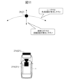
- Step S1 First, the line of sight direction movement determination unit 13 calculates the line of sight direction component Vrad of the object ground speed from the object ground speed VTA calculated by the object ground speed calculation unit 12 as shown in FIG.
- Step S2 Next, the line-of-sight direction component V rad of the object ground speed calculated in step S1 is used to determine whether the object is stationary or moving. That is, it is determined whether the line-of-sight direction component V rad of the object ground speed is within the range from the first threshold value to the second threshold value. When the line-of-sight direction component V rad of the object ground speed is within the range from the first threshold value to the second threshold value, it can be determined that the object is not moving in the line-of-sight direction. The line-of-sight direction component is determined to correspond to a stationary object, and step S3 is performed. When the line-of-sight direction component V rad of the object ground speed is outside the range from the first threshold value to the second threshold value, it is determined that the line-of-sight direction component is moving, and step S4 is performed.
- Step S3 Since the line of sight direction component was determined to correspond to a stationary object in step S2, if the object is also stationary in the circumferential direction, the object can be determined to be stationary. Therefore, the circumferential direction movement determination unit 14 is executed to determine whether the object is stationary or moving.
- Step S4 In step S3, the line-of-sight direction component is determined to correspond to a moving object. Since the line-of-sight velocity component of the radar 21a is a result of direct measurement, the circumferential direction movement determination unit 14 is not executed, and the object is determined to be a moving object.
- Step S11 First, the line of sight direction movement determination unit 13 calculates the circumferential component V cir of the object ground speed from the object ground speed V TA calculated by the object ground speed calculation unit 12 as shown in FIG.
- Step S12 Next, using the circumferential component V cir of the object ground speed calculated in step S11, it is determined whether the object is moving in the first (counterclockwise or left) direction of the circumferential component. That is, it is determined whether the circumferential component V cir of the object ground speed is within the range from the first threshold value to the second threshold value (within the range of movement in the first direction). If the circumferential component V cir of the object ground speed is within the range of movement in the first direction, step S13 is performed to add the reliability in the first direction. If the circumferential component V cir of the object ground speed is outside the range of movement in the first direction, it is determined that the object is stationary, and step S14 is performed to subtract the reliability in the first direction. For the addition and subtraction of the first direction reliability, which is an index showing the movement of the object in this first direction, a plurality of reliability thresholds and reliability addition and subtraction values may be used using a table or the like.
- Step S13 Based on the determination result in step S12, it is determined that the object is moving in a first (counterclockwise or left) direction, and the first directional reliability is added.
- Step S14 Based on the determination result of step S12, the object is determined to be a stationary object, and the first directional reliability is subtracted.
- Step S15 Next, using the circumferential component V cir of the object ground speed calculated in step S11, it is determined whether the object is moving in the second (clockwise or right) direction of the circumferential component. That is, it is determined whether the circumferential component V cir of the object ground speed is within the range from the third threshold value to the fourth threshold value (within the range of movement in the second direction). If the circumferential component V cir of the object ground speed is within the range of movement in the second direction, step S16 is performed to add the reliability in the second direction. If the circumferential component V cir of the object ground speed is outside the range of movement in the second direction, it is determined that the object is stationary, and step S17 is performed to subtract the reliability in the second direction. For the addition and subtraction of the second direction reliability, which is an index showing the movement of the object in the second direction opposite to the first direction, a plurality of reliability thresholds and reliability addition and subtraction values may be used using a table or the like.
- Step S16 Based on the determination result in step S15, it is determined that the object is moving in the second (clockwise or right) direction, and the second directional reliability is added.
- Step S17 Based on the determination result of step S15, the object is determined to be a stationary object, and the second directional reliability is subtracted.
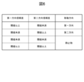
- Step S18 The first direction reliability and the second direction reliability obtained by performing addition and subtraction in steps S13, S14 based on step S12 and steps S16, S17 based on step S15 are used to determine whether the object is stationary or moving, based on the truth table of Fig. 6.
- the object is determined to be moving in the first direction (in other words, the moving direction of the moving object is the first direction).
- the second direction reliability is equal to or greater than the threshold
- the object is determined to be moving in the second direction (in other words, the moving direction of the moving object is the second direction).
- the object When both the first direction reliability and the second direction reliability are less than the threshold, the object is determined to be stationary since it is not moving. When both the first direction reliability and the second direction reliability are equal to or greater than the threshold, the object is determined to be diverging and is determined to be stationary.
- the threshold for the first direction reliability and the threshold for the second direction reliability may be the same value or different values.
- stationary objects are recognized as stationary objects without being erroneously judged as moving objects, and the accuracy of separating moving and stationary objects can be improved. This makes it possible to determine the possibility of a collision with the appropriate object and implement warnings and control.
- Example 2 a vehicle control device 10 which is an object detection device according to a second embodiment of the present invention will be described with reference to Fig. 11 to Fig. 13.
- a difference when the object recognition sensor 21 used in the first embodiment is changed from the radar 21a to a monocular camera 21b will be described.
- the radar 21a has high accuracy in the line of sight direction but poor accuracy in the circumferential direction (angular errors are likely to occur).
- the monocular camera 21b has poor accuracy in the line of sight direction (distance errors are likely to occur) but high accuracy in the circumferential direction. For this reason, this embodiment is applied to line of sight directions where there is a risk of accuracy deteriorating.
- the order of processing which in the first embodiment was the object ground speed calculation unit 12, the line of sight movement determination unit 13, and the circumferential movement determination unit 14, is changed in the second embodiment to the object ground speed calculation unit 12, the circumferential movement determination unit 14, and the line of sight movement determination unit 13.
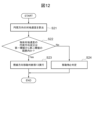
- the circumferential direction movement determination unit 14 uses the line of sight direction movement determination unit 13 of Example 1 applied to the circumferential direction as shown in FIG. 12.Furthermore, the line of sight direction movement determination unit 13 uses the line of sight direction movement determination unit 14 of Example 1 applied to the line of sight as shown in FIG. 13.By carrying out the process of FIG. 13, the line of sight direction movement determination unit 13 can determine an object moving in the first (approaching) direction of the line of sight (in other words, the moving direction of the moving object is the first (approaching) direction), an object moving in the second (away) direction of the line of sight (in other words, the moving direction of the moving object is the second (away) direction), or a stationary object.
- stationary objects are recognized as stationary objects without being erroneously judged as moving objects, and the accuracy of separating moving and stationary objects can be improved. This makes it possible to determine the possibility of a collision with the appropriate object and implement warnings and control.
- the process determines whether an object (detection target) is stationary or moving only when the speed of the vehicle 1 is below a predetermined value, particularly when the vehicle 1 is stopped, and only when the difference in the line-of-sight speed of stationary objects due to angle is small, and does not make a determination when the effect of position changes is large, thereby effectively reducing processing time.
- the object detection device (vehicle control device 10) of this embodiment has the following features: Obtaining a relative position and a relative speed between the vehicle and a detection target object around the vehicle detected by an object recognition sensor 21 (radar 21a or monocular camera 21b) mounted on the vehicle; a ground speed acquisition unit (object ground speed calculation unit 12) that acquires a ground speed of the detection object based on the relative position, the relative speed, the speed of the vehicle, and a yaw rate of the vehicle; Based on the ground speed, a first direction reliability is obtained, which is an index indicating the movement of the detection object in a predetermined first direction (a leftward direction in a circumferential direction centered on the object recognition sensor 21, or an approaching direction in a line of sight direction of the object recognition sensor 21); Based on the ground speed, a second direction reliability is obtained, which is an index indicating the movement of the detection object in a second direction (a rightward direction in a circumferential direction centered on
- the object detection method of the present embodiment is an object detection method executed by a control unit (vehicle control device 10) mounted on a vehicle,
- the control unit Obtaining a relative position and a relative speed between the vehicle and a detection target object around the vehicle detected by an object recognition sensor 21 (radar 21a or monocular camera 21b) mounted on the vehicle; acquiring a ground speed of the detection object based on the relative position, the relative speed, the speed of the vehicle, and a yaw rate of the vehicle;
- a first direction reliability is obtained, which is an index indicating the movement of the detection object in a predetermined first direction (a leftward direction in a circumferential direction centered on the object recognition sensor 21, or an approaching direction in a line of sight direction of the object recognition sensor 21);
- a second direction reliability is obtained, which is an index indicating the movement of the detection object in a second direction (a rightward direction in a circumferential direction centered on the object recognition sensor 21, or a direction away from the object
- the reliability broken down into the direction of movement (for example, according to separate reliability settings for the left and right directions) is used to determine whether the detected object is stationary or moving, thereby preventing the object from being mistakenly determined to be a crossing object.
- the present invention is not limited to the above-mentioned embodiment, but includes various modifications.
- the above-mentioned embodiment is described in detail to explain the present invention in an easy-to-understand manner, and is not necessarily limited to having all of the configurations described.
- each of the above configurations, functions, processing units, processing means, etc. may be realized in hardware, for example by designing some or all of them as an integrated circuit.
- each of the above configurations, functions, etc. may be realized in software by a processor interpreting and executing a program that realizes each function.
- Information such as the programs, tables, files, etc. that realize each function can be stored in a memory, a recording device such as a hard disk or SSD (Solid State Drive), or a recording medium such as an IC card, SD card, DVD, etc.
Landscapes
- Engineering & Computer Science (AREA)
- Radar, Positioning & Navigation (AREA)
- Remote Sensing (AREA)
- Physics & Mathematics (AREA)
- General Physics & Mathematics (AREA)
- Computer Networks & Wireless Communication (AREA)
- Mechanical Engineering (AREA)
- Transportation (AREA)
- Automation & Control Theory (AREA)
- Electromagnetism (AREA)
- Traffic Control Systems (AREA)
- Radar Systems Or Details Thereof (AREA)
- Burglar Alarm Systems (AREA)
Abstract
Description
以下、図2から図10を用いて、本発明の実施例1に係る物体検知装置である車両制御装置10を説明する。
次に、本実施例の車両制御装置10のシステム構成を説明する。図2に示すように、物体検知装置である車両制御装置10は、パラメータ保存部11、物体対地速度算出部12、視線方向移動判断部13、円周方向移動判断部14、警報部15を備えている。そして、物体対地速度算出部12、視線方向移動判断部13、円周方向移動判断部14、警報部15による処理を周期的に実行し、所定条件を満たす場合に、警報要求を作成し、警報装置31に出力する。なお、車両制御装置10は、具体的には、CPU等の演算装置、半導体メモリ等の記憶装置、および、通信装置などのハードウェアを備えたECU(Electronic Control Unit)である。そして、記憶装置にロードされたプログラムを演算装置が実行することで、視線方向移動判断部13等の各機能を実現するが、以下では、このような周知技術を適宜省略しながら説明する。
まず、視線方向移動判断部13は、図3のように物体対地速度算出部12で算出した物体対地速度VTAから、Vrad=VTAcosθを用いて物体対地速度の視線方向成分Vradを算出する。
次に、ステップS1で算出した物体対地速度の視線方向成分Vradを用いて、物体が静止物か移動物かの判断を行う。すなわち、物体対地速度の視線方向成分Vradが第一閾値から第二閾値の範囲内か否かの判断を行う。物体対地速度の視線方向成分Vradが第一閾値から第二閾値の範囲内の時、視線方向に移動していない物体と判断できる。視線方向成分は静止物相当と判断し、ステップS3を実施する。物体対地速度の視線方向成分Vradが第一閾値から第二閾値の範囲外の時、視線方向成分は移動していると判断し、ステップS4を実施する。
ステップS2で視線方向成分は静止物相当と判断したため、円周方向でも静止物であれば、物体は静止物と判断できる。そのため、円周方向移動判断部14を実行し、物体が静止物か移動物かの判断を行う。
ステップS3で視線方向成分は移動物相当と判断している。レーダ21aの視線速度成分は、直接計測した結果であるため、円周方向移動判断部14を実行せず、物体は移動物と判断する。
まず、視線方向移動判断部13は、図3のように物体対地速度算出部12で算出した物体対地速度VTAから、Vcir=VTAsinθを用いて物体対地速度の円周方向成分Vcirを算出する。
次に、ステップS11で算出した物体対地速度の円周方向成分Vcirを用いて、円周方向成分の第一(反時計回り又は左)方向に移動しているかの判定を行う。すなわち、物体対地速度の円周方向成分Vcirが第一閾値から第二閾値の範囲内(第一方向の移動の範囲内)か否かの判定を行う。物体対地速度の円周方向成分Vcirが第一方向の移動の範囲内であれば、第一方向の信頼度を加算するため、ステップS13を実施する。物体対地速度の円周方向成分Vcirが第一方向の移動の範囲外であれば、静止物と判断し、第一方向の信頼度を減算するため、ステップS14を実施する。この第一方向に対する物体の移動を示す指標である第一方向信頼度の加減算には、テーブル等を用いて複数の信頼度の閾値及び信頼度の加減算値を使用してもよい。
ステップS12の判断結果に基づいて、第一(反時計回り又は左)方向への移動物と判断し、第一方向信頼度の加算を実施する。
ステップS12の判断結果に基づいて、静止物と判断し、第一方向信頼度の減算を実施する。
次に、ステップS11で算出した物体対地速度の円周方向成分Vcirを用いて、円周方向成分の第二(時計回り又は右)方向に移動しているかの判定を行う。すなわち、物体対地速度の円周方向成分Vcirが第三閾値から第四閾値の範囲内(第二方向の移動の範囲内)か否かの判定を行う。物体対地速度の円周方向成分Vcirが第二方向の移動の範囲内であれば、第二方向の信頼度を加算するため、ステップS16を実施する。物体対地速度の円周方向成分Vcirが第二方向の移動の範囲外であれば、静止物と判断し、第二方向の信頼度を減算するため、ステップS17を実施する。この第一方向と反対の方向である第二方向に対する物体の移動を示す指標である第二方向信頼度の加減算には、テーブル等を用いて複数の信頼度の閾値及び信頼度の加減算値を使用してもよい。
ステップS15の判断結果に基づいて、第二(時計回り又は右)方向への移動物と判断し、第二方向信頼度の加算を実施する。
ステップS15の判断結果に基づいて、静止物と判断し、第二方向信頼度の減算を実施する。
ステップS12に基づいてステップS13、S14及びステップS15に基づいてステップS16、S17で加減算を実施して取得した第一方向信頼度及び第二方向信頼度を、図6の真理値表に基づいて、静止物及び移動方向を判断する。第一方向信頼度のみ閾値以上だった時(第二方向信頼度は閾値未満)、第一方向に移動する物体(言い換えると、移動物の移動方向が第一方向)と判断する。第二方向信頼度のみ閾値以上だった時(第一方向信頼度は閾値未満)、第二方向に移動する物体(言い換えると、移動物の移動方向が第二方向)と判断する。第一方向信頼度及び第二方向信頼度の両方が閾値未満だった時、物体は移動していないため、静止物と判断する。第一方向信頼度及び第二方向信頼度の両方が閾値以上だった時、発散している物体と判断し、静止物と判断する。
課題が発生した時の状況に対して、本実施例を適用した結果を説明する。シナリオとしては、図7のように、静止物(壁等)2cと検知点が同じになるような静止物(構造物)2bが存在し、自車1及び物体2ともに静止している状態となっている。測定データ(物体対地速度の円周方向成分Vcir)に対して、従来手法である図8のパラメータを適用した結果と本実施例1で設定した図9のパラメータを適用した結果を比較した。
次に、図11から図13を用いて、本発明の実施例2に係る物体検知装置である車両制御装置10を説明する。実施例2では、実施例1に使用する物体認識センサ21をレーダ21aから単眼カメラ21bに変更した時の差分について説明する。
次に、図14を用いて、本発明の実施例3を説明する。実施例3では、実施例1の判定部である円周方向移動判断部14(又は、実施例2の判定部である視線方向移動判断部13)を低速(車速が所定値以下)又は停止時のみ実施する理由を記載する。
以上説明したように、本実施例の物体検知装置(車両制御装置10)は、
車両に搭載された物体認識センサ21(レーダ21a、又は、単眼カメラ21b)で検出した、前記車両の周囲の検出対象物と前記車両との相対位置及び相対速度を取得し、
前記相対位置、前記相対速度、前記車両の速度、及び前記車両のヨーレートに基づいて前記検出対象物の対地速度を取得する対地速度取得部(物体対地速度算出部12)と、
前記対地速度に基づいて、所定の第一方向(物体認識センサ21を中心とした円周方向における左方向、又は、物体認識センサ21の視線方向における接近方向)に対する前記検出対象物の移動を示す指標である第一方向信頼度を取得し、
前記対地速度に基づいて、前記第一方向と反対の方向である第二方向(物体認識センサ21を中心とした円周方向における右方向、又は、物体認識センサ21の視線方向における離間方向)に対する前記検出対象物の移動を示す指標である第二方向信頼度を取得し、
前記第一方向信頼度と前記第二方向信頼度に基づいて前記検出対象物が静止物であるか移動物であるかを判定する判定部(円周方向移動判断部14、又は、視線方向移動判断部13)と、を備える。
前記コントロールユニットが、
前記車両に搭載された物体認識センサ21(レーダ21a、又は、単眼カメラ21b)で検出した、前記車両の周囲の検出対象物と前記車両との相対位置及び相対速度を取得し、
前記相対位置、前記相対速度、前記車両の速度、及び前記車両のヨーレートに基づいて前記検出対象物の対地速度を取得し、
前記対地速度に基づいて、所定の第一方向(物体認識センサ21を中心とした円周方向における左方向、又は、物体認識センサ21の視線方向における接近方向)に対する前記検出対象物の移動を示す指標である第一方向信頼度を取得し、
前記対地速度に基づいて、前記第一方向と反対の方向である第二方向(物体認識センサ21を中心とした円周方向における右方向、又は、物体認識センサ21の視線方向における離間方向)に対する前記検出対象物の移動を示す指標である第二方向信頼度を取得し、
前記第一方向信頼度と前記第二方向信頼度に基づいて前記検出対象物が静止物であるか移動物であるかを判定する。
10 車両制御装置(物体検知装置)
11 パラメータ保存部
12 物体対地速度算出部(対地速度取得部)
13 視線方向移動判断部(実施例2の判定部)
14 円周方向移動判断部(実施例1の判定部)
15 警報部
21 物体認識センサ
21a レーダ
21b 単眼カメラ
22 車速センサ
23 ステアリング角度センサ
24 ヨーレートセンサ
31 警報装置
2 物体
2a 移動物(歩行者等)
2b 静止物(電信柱、標識等)
2c 静止物(壁等)
VTA 物体対地速度
Vrad 物体対地速度の視線方向成分
Vcir 物体対地速度の円周方向成分
Claims (12)
- 車両に搭載された物体認識センサで検出した、前記車両の周囲の検出対象物と前記車両との相対位置及び相対速度を取得し、
前記相対位置、前記相対速度、前記車両の速度、及び前記車両のヨーレートに基づいて前記検出対象物の対地速度を取得する対地速度取得部と、
前記対地速度に基づいて、所定の第一方向に対する前記検出対象物の移動を示す指標である第一方向信頼度を取得し、
前記対地速度に基づいて、前記第一方向と反対の方向である第二方向に対する前記検出対象物の移動を示す指標である第二方向信頼度を取得し、
前記第一方向信頼度と前記第二方向信頼度に基づいて前記検出対象物が静止物であるか移動物であるかを判定する判定部と、を備える物体検知装置。 - 請求項1に記載の物体検知装置であって、
前記第一方向は、前記物体認識センサを中心とした円周方向における左方向であり、前記第二方向は、前記物体認識センサを中心とした円周方向における右方向である、物体検知装置。 - 請求項2に記載の物体検知装置であって、
前記物体認識センサは、レーダである、物体検知装置。 - 請求項1に記載の物体検知装置であって、
前記第一方向は、前記物体認識センサの視線方向における接近方向であり、前記第二方向は、前記物体認識センサの視線方向における離間方向である、物体検知装置。 - 請求項4に記載の物体検知装置であって、
前記物体認識センサは、単眼カメラである、物体検知装置。 - 請求項1に記載の物体検知装置であって、
前記判定部は、前記車両の速度が所定値以下であるときに、前記検出対象物が静止物であるか移動物であるかを判定する、物体検知装置。 - 請求項6に記載の物体検知装置であって、
前記判定部は、前記車両が停車しているときに、前記検出対象物が静止物であるか移動物であるかを判定する、物体検知装置。 - 請求項1に記載の物体検知装置であって、
前記判定部は、前記第一方向信頼度及び前記第二方向信頼度の両方が所定の閾値未満であるとき、前記検出対象物を静止物と判定する、物体検知装置。 - 請求項1に記載の物体検知装置であって、
前記判定部は、前記第一方向信頼度及び前記第二方向信頼度の両方が所定の閾値以上であるとき、前記検出対象物を静止物と判定する、物体検知装置。 - 請求項1に記載の物体検知装置であって、
前記判定部は、前記第一方向信頼度が所定の閾値以上、かつ前記第二方向信頼度が前記閾値未満であるとき、または前記第一方向信頼度が前記閾値未満、かつ前記第二方向信頼度が前記閾値以上であるとき、前記検出対象物を移動物と判定する、物体検知装置。 - 請求項10に記載の物体検知装置であって、
前記判定部は、前記第一方向信頼度が所定の閾値以上、かつ前記第二方向信頼度が前記閾値未満であるとき、前記移動物の移動方向が前記第一方向であり、前記第一方向信頼度が前記閾値未満、かつ前記第二方向信頼度が前記閾値以上であるとき、前記移動物の移動方向が前記第二方向である、と判定する、物体検知装置。 - 車両に搭載されたコントロールユニットが実行する物体検知方法であって、
前記コントロールユニットが、
前記車両に搭載された物体認識センサで検出した、前記車両の周囲の検出対象物と前記車両との相対位置及び相対速度を取得し、
前記相対位置、前記相対速度、前記車両の速度、及び前記車両のヨーレートに基づいて前記検出対象物の対地速度を取得し、
前記対地速度に基づいて、所定の第一方向に対する前記検出対象物の移動を示す指標である第一方向信頼度を取得し、
前記対地速度に基づいて、前記第一方向と反対の方向である第二方向に対する前記検出対象物の移動を示す指標である第二方向信頼度を取得し、
前記第一方向信頼度と前記第二方向信頼度に基づいて前記検出対象物が静止物であるか移動物であるかを判定する、物体検知方法。
Priority Applications (5)
| Application Number | Priority Date | Filing Date | Title |
|---|---|---|---|
| CN202380094251.8A CN120693540A (zh) | 2023-02-28 | 2023-02-28 | 物体检测装置及物体检测方法 |
| DE112023005433.9T DE112023005433T5 (de) | 2023-02-28 | 2023-02-28 | Objekterfassungsvorrichtung und objekterfassungsverfahren |
| JP2025503284A JP7817495B2 (ja) | 2023-02-28 | 2023-02-28 | 物体検知装置及び物体検知方法 |
| PCT/JP2023/007257 WO2024180652A1 (ja) | 2023-02-28 | 2023-02-28 | 物体検知装置及び物体検知方法 |
| JP2026017576A JP2026063554A (ja) | 2023-02-28 | 2026-02-05 | 車両制御装置、物体検知方法及び車両制御システム |
Applications Claiming Priority (1)
| Application Number | Priority Date | Filing Date | Title |
|---|---|---|---|
| PCT/JP2023/007257 WO2024180652A1 (ja) | 2023-02-28 | 2023-02-28 | 物体検知装置及び物体検知方法 |
Publications (1)
| Publication Number | Publication Date |
|---|---|
| WO2024180652A1 true WO2024180652A1 (ja) | 2024-09-06 |
Family
ID=92589465
Family Applications (1)
| Application Number | Title | Priority Date | Filing Date |
|---|---|---|---|
| PCT/JP2023/007257 Ceased WO2024180652A1 (ja) | 2023-02-28 | 2023-02-28 | 物体検知装置及び物体検知方法 |
Country Status (4)
| Country | Link |
|---|---|
| JP (2) | JP7817495B2 (ja) |
| CN (1) | CN120693540A (ja) |
| DE (1) | DE112023005433T5 (ja) |
| WO (1) | WO2024180652A1 (ja) |
Citations (8)
| Publication number | Priority date | Publication date | Assignee | Title |
|---|---|---|---|---|
| JPH05232214A (ja) * | 1992-02-21 | 1993-09-07 | Fujitsu Ten Ltd | Fm−cwレーダ装置 |
| JP2009104363A (ja) * | 2007-10-23 | 2009-05-14 | Tamagawa Gakuen | 物体識別装置 |
| JP2010173511A (ja) * | 2009-01-30 | 2010-08-12 | Nissan Motor Co Ltd | 車両用運転支援装置および車両用運転支援方法 |
| JP2014035669A (ja) * | 2012-08-09 | 2014-02-24 | Honda Motor Co Ltd | 物体位置検知装置 |
| JP2016121918A (ja) * | 2014-12-24 | 2016-07-07 | 新日本無線株式会社 | マイクロ波ドップラー移動体検知装置 |
| JP2018112467A (ja) * | 2017-01-11 | 2018-07-19 | 株式会社デンソーテン | レーダ装置および物標検知方法 |
| JP2021152476A (ja) * | 2020-03-24 | 2021-09-30 | キヤノン株式会社 | 情報処理装置、情報処理方法、及びプログラム |
| JP2022190849A (ja) * | 2021-06-15 | 2022-12-27 | 株式会社デンソーテン | 抽出装置および抽出方法 |
-
2023
- 2023-02-28 DE DE112023005433.9T patent/DE112023005433T5/de active Pending
- 2023-02-28 WO PCT/JP2023/007257 patent/WO2024180652A1/ja not_active Ceased
- 2023-02-28 CN CN202380094251.8A patent/CN120693540A/zh active Pending
- 2023-02-28 JP JP2025503284A patent/JP7817495B2/ja active Active
-
2026
- 2026-02-05 JP JP2026017576A patent/JP2026063554A/ja active Pending
Patent Citations (8)
| Publication number | Priority date | Publication date | Assignee | Title |
|---|---|---|---|---|
| JPH05232214A (ja) * | 1992-02-21 | 1993-09-07 | Fujitsu Ten Ltd | Fm−cwレーダ装置 |
| JP2009104363A (ja) * | 2007-10-23 | 2009-05-14 | Tamagawa Gakuen | 物体識別装置 |
| JP2010173511A (ja) * | 2009-01-30 | 2010-08-12 | Nissan Motor Co Ltd | 車両用運転支援装置および車両用運転支援方法 |
| JP2014035669A (ja) * | 2012-08-09 | 2014-02-24 | Honda Motor Co Ltd | 物体位置検知装置 |
| JP2016121918A (ja) * | 2014-12-24 | 2016-07-07 | 新日本無線株式会社 | マイクロ波ドップラー移動体検知装置 |
| JP2018112467A (ja) * | 2017-01-11 | 2018-07-19 | 株式会社デンソーテン | レーダ装置および物標検知方法 |
| JP2021152476A (ja) * | 2020-03-24 | 2021-09-30 | キヤノン株式会社 | 情報処理装置、情報処理方法、及びプログラム |
| JP2022190849A (ja) * | 2021-06-15 | 2022-12-27 | 株式会社デンソーテン | 抽出装置および抽出方法 |
Also Published As
| Publication number | Publication date |
|---|---|
| JP2026063554A (ja) | 2026-04-10 |
| JP7817495B2 (ja) | 2026-02-18 |
| DE112023005433T5 (de) | 2025-10-30 |
| JPWO2024180652A1 (ja) | 2024-09-06 |
| CN120693540A (zh) | 2025-09-23 |
Similar Documents
| Publication | Publication Date | Title |
|---|---|---|
| US11900663B2 (en) | Computer-assisted or autonomous driving traffic sign recognition method and apparatus | |
| KR102506871B1 (ko) | 자율 주행 제어 장치 및 그의 전방차량 출발 알림 방법 | |
| CN110867132B (zh) | 环境感知的方法、装置、电子设备和计算机可读存储介质 | |
| US20150239472A1 (en) | Vehicle-installed obstacle detection apparatus having function for judging motion condition of detected object | |
| CN110667506B (zh) | 一种碰撞识别的方法、装置、设备及存储介质 | |
| JP6289767B1 (ja) | 故障検出装置、故障検出方法及び故障検出プログラム | |
| US11465625B2 (en) | Traffic safety control method, vehicle-mounted device and readable storage medium | |
| JPWO2013118247A1 (ja) | 物体検知装置 | |
| KR20200123308A (ko) | 카메라 신호 모니터링 장치 및 방법 | |
| JP6647466B2 (ja) | 故障検出装置、故障検出方法及び故障検出プログラム | |
| JP7474352B2 (ja) | 車両制御装置、および、車両制御方法 | |
| WO2020157844A1 (ja) | 計測装置、計測方法及び計測プログラム | |
| JP2010128637A (ja) | 制動準備促進装置 | |
| US20230249716A1 (en) | Vehicle, control device and control method therefor | |
| WO2021217485A1 (zh) | 一种车辆变道行为识别方法及装置 | |
| WO2018025632A1 (ja) | 撮像装置 | |
| CN116080665A (zh) | 车辆异常驾驶行为识别方法、装置及存储介质 | |
| US20250319867A1 (en) | Vehicle collision determination device | |
| JP7817495B2 (ja) | 物体検知装置及び物体検知方法 | |
| KR20230174784A (ko) | 주행 환경에 기반한 전방충돌방지 보조 방법 및 장치 | |
| JP2018136713A (ja) | ドライバの視界推定装置及び車両用制御装置 | |
| CN117935212A (zh) | 检测方法、装置和车辆 | |
| US10509122B2 (en) | Driving burden estimation device and driving burden estimation method | |
| KR102495609B1 (ko) | 차량 전방 충돌 방지 제어 장치 및 방법 | |
| JP2019171962A (ja) | 自動制動装置 |
Legal Events
| Date | Code | Title | Description |
|---|---|---|---|
| 121 | Ep: the epo has been informed by wipo that ep was designated in this application |
Ref document number: 23925209 Country of ref document: EP Kind code of ref document: A1 |
|
| WWE | Wipo information: entry into national phase |
Ref document number: 2025503284 Country of ref document: JP |
|
| WWE | Wipo information: entry into national phase |
Ref document number: 202380094251.8 Country of ref document: CN |
|
| WWE | Wipo information: entry into national phase |
Ref document number: 112023005433 Country of ref document: DE |
|
| WWP | Wipo information: published in national office |
Ref document number: 202380094251.8 Country of ref document: CN |
|
| WWP | Wipo information: published in national office |
Ref document number: 112023005433 Country of ref document: DE |
|
| 122 | Ep: pct application non-entry in european phase |
Ref document number: 23925209 Country of ref document: EP Kind code of ref document: A1 |