WO2024180639A1 - 撮影システム、撮影方法、移動体制御装置及びプログラム - Google Patents
撮影システム、撮影方法、移動体制御装置及びプログラム Download PDFInfo
- Publication number
- WO2024180639A1 WO2024180639A1 PCT/JP2023/007177 JP2023007177W WO2024180639A1 WO 2024180639 A1 WO2024180639 A1 WO 2024180639A1 JP 2023007177 W JP2023007177 W JP 2023007177W WO 2024180639 A1 WO2024180639 A1 WO 2024180639A1
- Authority
- WO
- WIPO (PCT)
- Prior art keywords
- area
- photographing
- target area
- shooting
- control device
- Prior art date
- Legal status (The legal status is an assumption and is not a legal conclusion. Google has not performed a legal analysis and makes no representation as to the accuracy of the status listed.)
- Ceased
Links
Images


Classifications
-
- H—ELECTRICITY
- H04—ELECTRIC COMMUNICATION TECHNIQUE
- H04N—PICTORIAL COMMUNICATION, e.g. TELEVISION
- H04N23/00—Cameras or camera modules comprising electronic image sensors; Control thereof
- H04N23/60—Control of cameras or camera modules
Definitions
- the present invention relates to a photography system, a photography method, a mobile object control device, and a program.
- the problem of the patent document 1 is to disclose various aspects of a system and method for capturing a moving scene using multiple cameras in a network (abstract).
- the system of the patent document 1 includes a plurality of unmanned aerial vehicles (UAVs).
- Each of the plurality of UAVs is accompanied by an imaging device configured to capture a plurality of images.
- a first UAV of the plurality of UAVs includes a first imaging device configured to capture a first series of images of one or more stationary and/or moving objects.
- the first UAV is configured to receive focus lens information, a current position, and a current orientation from the one or more imaging devices. Determine a target position and a target orientation for each of the one or more imaging devices.
- Patent Document 1 mentions facilities such as stadiums as an example of moving scenes to be photographed ([0003]). It also introduces a method of using triangulation as an example of a method for setting the target position and target orientation of each imaging device ([0032], Figures 5A to 5D). As another example, it also shows an example of photographing a golf player from various angles ([0153], Figures 6A to 6C).
- Patent Document 1 discloses the use of multiple unmanned aerial vehicles (UAVs) to take photographs at facilities such as stadiums.
- the imaging device of each UAV is controlled using a target position and a target orientation.
- a normal match is played using the entire soccer court (full court).
- full court may be used, there are also cases where only half of a soccer court (half court) is used.
- the size of each soccer court often differs.
- baseball field a normal match is played using the entire baseball field.
- Patent Document 1 does not consider cases where the usable area or the area to be photographed of one sports field (soccer field, baseball field, etc.) changes, or cases where the size of the area to be photographed changes in different sports fields.
- Futsal is also a sport similar to soccer.
- a (full) futsal court is smaller than a (full) soccer court.
- Patent Document 1 does not fully consider the case where the size or shape of the usable area or the area to be photographed differs in different stadiums (soccer courts or futsal courts) where similar sports such as soccer and futsal are played.
- the present invention was made in consideration of the above problems, and aims to provide a photography system, photography method, mobile object control device, and program that can take pictures according to differences in the area to be used or the area to be photographed in a facility such as a stadium.
- An imaging system includes: A photographing moving body having a photographing camera; A moving body control device that controls the movement of the moving body and the photographing during the photographing,
- the mobile object control device includes a photography target area setting unit that detects a photography target area, which is all or a part of a stadium, or receives a user input of the photography target area, and sets the photography target area or its area size;
- the moving object control device is further characterized in that it switches at least one of the movement conditions of the moving object during the shooting or the shooting conditions in accordance with an area size of the shooting target area.
- At least one of the moving conditions of the moving body or the shooting conditions used by the moving body control device during shooting is switched according to the area size of the area to be shot. Therefore, even if the area size differs for each stadium, shooting according to the area size is possible. Furthermore, even when shooting at the same stadium, it is possible to make the moving conditions or shooting conditions when the entire stadium is used different from the moving conditions or shooting conditions when only part of the stadium is used. Therefore, shooting according to differences in the area used or the area to be shot at the stadium becomes possible.
- the area size may be the area of the area to be photographed. Alternatively, if the area to be photographed is rectangular, the area size may be the length of the short side or the length of the long side of the area to be photographed. Alternatively, the area size may be a combination of the area, the length of the short side, or the length of the long side.
- the shooting target area setting unit may set the shooting target area or its area size by detecting the shooting target area which is all or part of the one stadium or by receiving user input of the shooting target area, and distinguishing whether it is all or part of the one stadium. Furthermore, the shooting target area setting unit may make at least one of the movement conditions of the moving object or the shooting conditions at the time of shooting different for the same stadium when the shooting target area is the entire stadium and when it is part of the stadium. This makes it possible to use the movement conditions or shooting conditions appropriate for the shooting target area when it is part of a stadium (for example, when a competition is held using a half court).
- the mobile control device may switch the area of the target flight altitude or permitted flight altitude during shooting depending on the area size of the area to be shot. This makes it possible to precisely control the flight altitude for each area size of the area to be shot in one stadium.
- the mobile body control device may set multiple objects of interest for a viewer of the image acquired by the photographic camera.
- the mobile body control device may identify the positions of the multiple objects of interest in the image acquired by the photographic camera.
- the mobile body control device may calculate a centroid from the positions of the multiple objects of interest.
- the mobile body control device may control the angle of view of the photographic camera so that the centroid is located at a predetermined position (e.g., the center) of the acquired image. This makes it possible to adjust the angle of view so that the multiple objects of interest are easily visible to the viewer of the image acquired by the photographic camera.
- the mobile object control device may switch the allowable range of the shooting direction or the target shooting direction during shooting according to the area size of the shooting target area. This makes it possible to precisely control the shooting direction for each area size of the shooting target area.
- the mobile object control device may switch the allowable range of the zoom amount or the target zoom amount during shooting according to the area size of the area to be shot. This makes it possible to precisely control the zoom amount for each area size of the area to be shot.
- the mobile control device may switch the area of the geofence in the vertical or horizontal direction during shooting depending on the area size of the area to be shot. This makes it possible to set a geofence precisely for each area size of the area to be shot.
- the mobile object control device may switch the range of permitted flight altitudes during shooting according to the area size of the area to be shot, and allow manual operation of the altitude of the shooting mobile object within the range of permitted flight altitudes. This allows manual operation of the flight altitude according to the area size of the area to be shot.
- the mobile object control device may set multiple geofences divided by the areas in which the mobile object can fly.
- the mobile object control device may switch the timing of switching the geofences when switching between flight areas depending on the area size of the area to be photographed. This makes it possible to precisely set the switching timing of the flight geofence for each area size of the area to be photographed.
- the multiple flight modes for photography may be switchable between an overhead photography mode in which the entire photography target area is photographed from an overhead view, and a partial photography mode in which a portion of the photography target area is photographed.
- the mobile control device may set a joint geofence that combines the geofence used in the flight mode before the switch and the geofence used in the flight mode after the switch. This makes it possible to fly smoothly when switching flight modes.
- the shooting target area setting unit may detect candidates for the shooting target area based on the surrounding image acquired by the moving body.
- the shooting target area setting unit may set the shooting target area or its area size by using the candidate shooting target area as is, or by having the user select or confirm the area through operation. This is expected to completely match the shooting target area (or shooting candidate area) detected when setting the shooting target area and the shooting target area used when normal shooting is performed. Therefore, for example, when the user checks the detection result of the shooting target area (or shooting candidate area) when setting the shooting target area, it is possible to increase the reliability of the shooting target area during normal shooting.
- the shooting target area setting unit may include a candidate area database that stores candidates for the shooting target area.
- the shooting target area setting unit may also extract the shooting target area candidates or their area sizes that match the user's specified conditions from the candidate area database and set them as the shooting target area or their area sizes. This makes it possible to easily set the shooting target area or its area size when the user has previously obtained information on the shooting candidate areas that the user wants to use as the shooting target area.
- the mobile object control device may change the target flight altitude, or the upper limit flight altitude, or the lower limit flight altitude based on the detected information of the external environment. This makes it possible to restrict the movement of the mobile object and ensure flight stability, for example, when an external environment occurs that affects the flight stability of the mobile object.
- the detected information of the external environment may be wind speed.
- the mobile body control device may lower the target flight altitude or the upper limit flight altitude. In this way, in an environment where strong winds are occurring, it is possible to improve flight stability by lowering the flight altitude of the mobile body.
- the external environment detection information may be the reception strength of satellite signals, or the number of artificial satellites receiving the satellite signals (number of communication satellites), or the elevation angle of the artificial satellite receiving the satellite signals.
- the mobile control device may increase at least one of the target flight altitude, the upper limit flight altitude, or the lower limit flight altitude when the reception strength falls below a reception strength threshold, or when the number of artificial satellites falls below a predetermined number, or when the elevation angle of the satellite falls below a predetermined angle. This makes it possible to change the flight state so as to increase the reception strength of satellite signals, for example.
- a photographing method includes the steps of: A photographing moving body having a photographing camera; A method for using an imaging system including a moving body control device that controls the movement and imaging of the moving body during imaging,
- the mobile object control device includes a photographing target area setting unit that sets the photographing target area or the area size thereof by detecting the photographing target area or by receiving a user input of the photographing target area,
- the moving object control device is further characterized in that it switches at least one of the movement conditions of the moving object during the shooting or the shooting conditions in accordance with an area size of the shooting target area.
- At least one of the moving conditions of the moving body or the shooting conditions used by the moving body control device during shooting is switched according to the area size of the area to be shot. Therefore, by making the moving conditions or shooting conditions different for each area size of the area to be shot, precise movement or shooting becomes possible.
- a moving object control device controls movement and photography of an imaging moving object having an imaging camera
- the mobile object control device includes a photographing target area setting unit that sets the photographing target area or the area size thereof by detecting the photographing target area or by receiving a user input of the photographing target area
- the moving body control device is characterized in that it switches at least one of the movement conditions of the moving body during shooting or the shooting conditions in accordance with the area size of the shooting target area.
- a program according to yet another aspect of the present invention is executed by a moving object control device that controls movement and photography of a photographing moving object having a photographing camera,
- the mobile object control device setting the imaging target area or its area size by detecting the imaging target area or by receiving a user input of the imaging target area; and switching at least one of the movement conditions of the moving object during shooting or the shooting conditions in accordance with the area size of the shooting target area.
- the present invention makes it possible to take photographs according to differences in the areas used or the areas to be photographed in facilities such as stadiums.
- FIG. 1 is a diagram showing the overall configuration of an imaging system according to an embodiment of the present invention
- FIG. 2 is a functional configuration diagram of the drone according to the embodiment.
- FIG. 2 is a simplified external perspective view of the drone according to the embodiment.
- FIG. 2 is a functional configuration diagram of the control device according to the embodiment.
- FIG. 2 is a front view showing an external appearance of the control device according to the embodiment in a simplified manner.
- FIG. 2 is a functional configuration diagram of a server according to the embodiment.
- 5 is a flowchart showing an overall flow of aerial photography control in the embodiment.
- 8 is a flowchart (details of S101 in FIG. 7) for setting a photographing target area in the embodiment.
- 10A to 10C are diagrams illustrating an example of the hovering operation of the drone when setting the photographing target area in the embodiment.
- 10 is a diagram showing an example of an operation screen for setting the photographing target area in the embodiment.
- 11A to 11C are diagrams illustrating examples of vertical and horizontal geofences in the overhead shooting mode and area flight mode set in the embodiment.
- 5A to 5C are diagrams showing examples of initial values of target flight altitudes and corresponding permitted flight areas in the overhead shooting mode and area flight mode, which are set in the embodiment.
- FIG. 4 is an explanatory diagram of a flight mode transition in the embodiment.
- FIG. 1A to 1C are diagrams illustrating examples of shooting reference positions of the drone used in the embodiment.
- Figure 16(A) is a diagram showing each shooting reference position when the entire stadium is set as the shooting target area in the embodiment
- Figure 16(B) is a diagram showing a simplified example of a screen displayed on the display unit of the control device corresponding to Figure 16(A).
- Figure 17(A) is a diagram showing each shooting reference position when half of the stadium is set as the shooting target area in the embodiment
- Figure 17(B) is a diagram showing a simplified example of a screen displayed on the display unit of the control device corresponding to Figure 17(A).
- FIG. 18(A) is a diagram showing, in a simplified manner, an example of a screen displayed on the display unit of the control device when the angle of view adjustment process is not performed in the embodiment
- FIG. 18(B) is a diagram showing, in a simplified manner, an example of a screen displayed on the display unit of the control device when the angle of view adjustment process is performed in the embodiment.
- 4 is a flowchart of flight stability control in the embodiment.
- 8 is a flowchart (details of S101 in FIG. 7) for setting a photographing target area in the first modified example.
- Figure 23 (A) is a diagram showing the positions of the short and long sides when the shooting target area is rectangular
- Figure 23 (B) is a diagram showing an example of the relationship between the short sides of the shooting target area and the flight conditions and shooting conditions in the second modified example
- Figure 23 (C) is a diagram showing an example of the relationship between the long sides of the shooting target area and the flight conditions and shooting conditions in the third modified example
- Figure 24 (A) is a diagram showing the shooting reference position 6, etc. when the entire stadium of the standard size is set as the shooting target area in the fourth modified example
- Figure 24 (B) is a diagram showing the shooting reference position 6, etc. when the entire stadium larger than the standard size is set as the shooting target area in the fourth modified example.
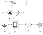
- FIG. 1 is an overall configuration diagram of an imaging system 10 (hereinafter also referred to as "system 10") according to one embodiment of the present invention.
- the system 10 uses a drone 20 to take aerial photographs of a predetermined area (facility) where people may be active, such as a competition held at a stadium 90 (FIG. 9, etc.) or an event held at an event venue.
- the system 10 has a control device 30 that allows a pilot to operate the drone 20, and a server 40 that manages the flight and imaging of the drone 20.
- a competition is one in which skills or abilities are competed against one another, and includes soccer and various other sports. It is also not limited to matches, but can also include practice sessions.
- a stadium is a place where a competition is held, and can include not only the area inside the court defined by the lines as shown in FIG. 9, but also the area outside the court.
- the present invention can also be applied to a photography system that photographs a subject area for any purpose, not limited to competitions or events.
- the drone 20 and the control device 30 are connected to each other via wireless communication (which may include communication via a base station 52).
- the control device 30 and the server 40 are connected to each other via a communication network 50 such as an Internet line.
- the drone 20 acquires satellite signals from an artificial satellite 54 to set its own position, etc.
- the configuration of the system 10 is not limited to that shown in FIG. 1, and other configurations may also be used (details will be described later).
- Fig. 2 is a functional configuration diagram of the drone 20 of this embodiment.
- Fig. 3 is a simplified external perspective view of the drone 20 of this embodiment.
- the drone 20 takes aerial photographs of a competition held in a stadium 90 (Fig. 9), an event held in an event venue, and the like.
- the drone 20 has a drone sensor group 200, a communication unit 210, a flight mechanism 220, a photography mechanism 230, and a drone control unit 240.
- drone refers to any flying object that has multiple rotors and the ability to autonomously control its attitude, regardless of the power source (electricity, prime mover, etc.), control method (wireless or wired, and fully autonomous or partially manually controlled, etc.), and whether manned or unmanned.
- Drones are also sometimes referred to as Unmanned Aerial Vehicles (UAVs), flying objects, multicopters, RPAS (Remote Piloted Aircraft System), or UAS (Unmanned Aircraft System), etc.
- the drone sensor group 200 includes various sensors arranged on the drone 20. Specifically, the drone sensor group 200 has a position measurement unit 201, a direction measurement unit 202, an altimeter 203, a speedometer 204, a gyro sensor 205, an obstacle sensor 206, an anemometer 207, etc. In addition to these, the drone sensor group 200 may include various sensors that acquire information such as temperature, air pressure, and acceleration.
- the position measurement unit 201 receives signals from the artificial satellites 54 ( Figure 1) and measures the position (absolute position) of the aircraft based on the signals.
- the position measurement unit 201 measures its current position using, for example, but not limited to, GNSS (Global Navigation Satellite System), GPS (Global Positioning System), etc.
- GNSS Global Navigation Satellite System
- GPS Global Positioning System
- RTK-GNSS Real Time Kinematic - Global Navigation Satellite System
- the position information includes at least two-dimensional coordinate information in a planar view (e.g., latitude, longitude), and preferably includes three-dimensional coordinate information including altitude information.
- the base station 52 which provides information on the reference points of fixed stations used for relative positioning such as RTK, is connected to the drone 20 and the control device 30 so that they can communicate wirelessly, making it possible to measure the position of the drone 20 with greater accuracy.
- the base station 52 can be omitted, or the accuracy of the position coordinate estimation of the base station 52 or drone 20 can be further improved.
- the position measurement unit 201 of this embodiment can determine the reception strength of the received signal from the satellite 54, the number of satellites 54 receiving the satellite signal, or the elevation angle of the satellite 54 receiving the satellite signal.
- the orientation measurement unit 202 measures the orientation (heading direction) of the aircraft.
- the orientation measurement unit 202 is composed of a geomagnetic sensor that measures the nose orientation (heading direction) of the drone 20 aircraft by measuring geomagnetism, a compass, etc.
- the altimeter 203 measures the altitude above ground (hereinafter referred to as "altitude H") as the distance from the ground below the drone 20 (vertically downward).
- the measured value of altitude H acquired by the altimeter 203 is also referred to as the measured altitude Hd.
- the speedometer 204 detects the flight speed of the drone 20.
- the gyro sensor 205 detects the angular velocity of the drone 20.
- the obstacle sensor 206 has multiple control cameras 208 ( Figure 3), and measures the position, speed vector, etc. of people positioned below the drone 20, etc. based on the acquired images.
- the anemometer 207 detects the wind direction and speed around the drone 20. If the drone 20 itself is moving, the wind direction and speed may be corrected using the direction and speed of movement of the drone 20.
- the communication unit 210 is capable of radio wave communication via the communication network 50 ( FIG. 1 ) and includes, for example, a radio wave communication module.
- the communication unit 210 is capable of communication with the control device 30 and the like via the communication network 50 (including the wireless base station 52).
- Flight mechanism 220 The flight mechanism 220 is a mechanism for flying the drone 20, and generates thrust for the drone 20 to fly and move in a desired direction. As shown in FIG. 2 and FIG. 3, the flight mechanism 220
- the rotor 221 includes a plurality of rotor actuators 222.
- the rotor actuators 222 include, for example, electric motors.
- Flight mechanism 220 may also be provided with a propeller guard (not shown) to prevent the propeller from interfering with obstacles.
- the number of rotors 221 constituting flight mechanism 220 is not particularly limited, but may include, for example, one, two, four, six, or eight rotors.
- Rotor 221 may be composed of a single propeller, or may be composed of multiple propellers arranged coaxially. The number and shape of the blades of each propeller are not particularly limited.
- the photographing mechanism 230 is a mechanism for photographing images of a competition in the stadium 90 (FIG. 9), an event in an event venue, etc., and has a camera 231, a camera holding unit 232, and an image processing unit 233.
- the camera 231 imaging device
- the camera 231 is disposed at the bottom of the main body of the drone 20, and outputs image data related to a peripheral image photographed around the drone 20.
- the camera 231 is a video camera (color camera) that photographs moving images.
- the moving images may include audio data acquired by a microphone (not shown). In addition to or instead of this, the camera 231 may also be configured to photograph still images.
- the orientation of the camera 231 (the attitude of the camera 231 relative to the body of the drone 20) can be adjusted by a camera actuator (not shown) built into the camera holding part 232. Alternatively, the position of the camera 231 relative to the body of the drone 20 may be fixed.
- the camera holding part 232 may have a mechanism for suppressing the transmission of shaking or vibration of the aircraft to the camera 231.
- the image processing part 233 performs predetermined image processing on the image data acquired by the camera 231.
- the image data acquired by the camera 231 can be transmitted to a memory part of the drone 20 itself, the control device 30, the server 40, etc.
- a part or all of the image processing part 233 may be positioned as part of the shooting control part 242 described later.
- the drone control unit 240 controls the entire drone 20, including flying and photographing the drone 20.
- the drone control unit 240 includes an input/output unit, a calculation unit, and a storage unit, which are not shown.
- the drone control unit 240 includes a calculation device such as a CPU (Central Processing Unit) for executing information processing, and storage devices such as a RAM (Random Access Memory) and a ROM (Read Only Memory).
- the drone control unit 240 includes a flight control unit 241 and a photography control unit 242.
- the flight control unit 241 controls the flight of the drone 20 (attitude control and flight operations of the aircraft from takeoff to flight and landing) via the flight mechanism 220.
- the flight control unit 241 has a processing unit, also called a flight controller.
- the processing unit can have one or more processors, such as a programmable processor (e.g., a central processing unit (CPU), MPU, or DSP).
- the processing unit has access to a memory (storage unit).
- the memory stores logic, code, and/or program instructions that the processing unit can execute to perform one or more steps.
- the memory may include, for example, a separable medium such as an SD card or RAM, or an external storage device.
- Various data acquired from the drone sensor group 200 may be directly transmitted to and stored in the memory. For example, video or still image data captured by the camera 231 can be recorded in the built-in memory or an external memory.
- the processing unit includes a control module configured to control the state of the drone 20.
- the control module controls the flight mechanism 220 (thrust generating unit) of the drone 20 to adjust the spatial arrangement, attitude angle, angular velocity, angular acceleration, angular jerk rate, and/or acceleration of the drone 20 having six degrees of freedom (translational motion x, y, and z, and rotational motion ⁇ x, ⁇ y, and ⁇ z).
- the control module can control one or more of the camera holding unit 232 and sensors.
- the flight control unit 241 can control the flight of the drone 20 based on control signals from the pilot device 30 or based on a preset autonomous flight program.
- the flight control unit 241 can also control the flight of the drone 20 by controlling the flight mechanism 220 (thrust generation unit) based on various information such as the area to be photographed, flight permitted/prohibited areas, information on the corresponding flight geofences, map information including two-dimensional or three-dimensional map data, the current position information of the drone 20, attitude information (heading information), speed information, and acceleration information, as well as any combination of these.
- area to be photographed refers to a two-dimensional location to be photographed (for example, the outline defining the stadium 90 (for example, the frame consisting of the touchlines and goal lines of a soccer field)).
- Fluor permitted/prohibited area refers to a three-dimensional unit of space that permits or prohibits flight of the drone 20.
- Geographic refers to a virtual boundary line, and in particular refers to a fence that is the boundary between a flight permitted area where a mobile object such as the drone 20 is permitted to fly or move and a flight prohibited area. Therefore, if a mobile object such as the drone 20 comes into contact with a geofence, flight or movement is restricted to prevent the aircraft from flying outside the flight permitted area.
- the photography control unit 242 controls photography by the drone 20 via the photography mechanism 230.
- FIG. 4 is a functional configuration diagram of the control device 30 of this embodiment.
- FIG. 5 is an external front view showing the control device 30 of this embodiment in a simplified manner.
- the control device 30 is a mobile information terminal that controls the drone 20 by the operation of the pilot and displays information received from the drone 20 (e.g., position, altitude, remaining battery level, camera image, etc.).
- the flight state (altitude, attitude, etc.) of the drone 20 is remotely controlled by the control device 30, but the drone 20 may also control it autonomously. In that case, when a flight command is transmitted from the pilot to the drone 20 via the control device 30, the drone 20 performs autonomous flight.
- manual operation may be possible during basic operations such as takeoff and return, and in an emergency.
- the control device 30 has an input/output unit 300 and a communication unit 310.
- the input/output unit 300 performs various inputs by a user such as a pilot, outputs to the user, and inputs and outputs signals between the drone 20 or the server 40.
- the input/output unit 300 has an operation input unit 320 and a display unit 330.
- the operation input unit 320 and the display unit 330 are connected to each other so that they can communicate with each other via wire or wirelessly.
- the control device 30 also has a calculation device such as a CPU for executing information processing, and storage devices such as a RAM and a ROM. Furthermore, the control device 30 of this embodiment receives and displays work instructions, etc. from the server 40.
- the communication unit 310 is disposed in the same housing as the operation input unit 320 or the display unit 330, and has a communication function for wirelessly communicating with the drone 20 by wireless communication using Wi-Fi, 2.4 GHz, and 5.6 to 5.8 GHz frequency bands.
- the communication unit 310 also has a wireless communication function for communicating with the server 40 via the Internet line 50 using a communication standard such as LTE (Long Term Evolution).
- LTE Long Term Evolution
- the drone 20 communicates with the server 40 via the control device 30, so that the system configuration is suitable for a case where the drone 20 and the control device 30 are located at a distance where they can directly communicate wirelessly (for example, visual flight by a pilot, etc.), but is not limited thereto.
- the operation input unit 320 accepts various inputs from a user such as a pilot, and inputs operation commands such as a flight direction and takeoff/landing when the pilot operates the drone 20.
- the operation input unit 320 accepts input operations that instruct the three-dimensional flight operation of the drone 20, including takeoff, landing, ascent, descent, rotation, forward movement, backward movement, left and right movement, etc.
- the operation input unit 320 of this embodiment includes a movement input unit 321, a drone attitude input unit 322, a camera attitude input unit 323, a camera zoom input unit 324, a flight mode switching unit 325, a shooting condition input unit 326, and a power input unit 327.
- the operation input unit 320 as hardware has a left input stick 340L, a right input stick 340R, a left two-way switch button 341L, a right two-way switch button 341R, and a menu button 342.
- the movement input unit 321 is an input unit that allows the pilot to move the drone 20 up and down, left and right, and forward and backward, and is composed of a right input stick 340R and a left input stick 340L. That is, when the right input stick 340R is moved upward (toward the rear), the drone 20 rises, and when the right input stick 340R is moved downward (toward the viewer), the drone 20 descends. When the right input stick 340R is moved to the right, the drone 20 moves right, and when the right input stick 340R is moved to the left, the drone 20 moves left. When the left input stick 340L is moved upward (toward the rear), the drone 20 moves forward, and when the left input stick 340L is moved downward (toward the viewer), the drone 20 moves backward.
- the drone attitude input unit 322 is an input unit that allows the pilot to control the attitude of the drone 20, and is composed of the left input stick 340L.
- the attitude of the drone 20 referred to here includes yaw rotation. In other words, when the left input stick 340L is moved to the right, the drone 20 turns right, and when the left input stick 340L is moved to the left, the drone 20 turns left.
- the camera attitude input section 323 is an input section for controlling the attitude of the photographing camera 231, and is composed of a right two-way switch button 341R and a right input stick 340R. That is, when the right side of the right two-way switch button 341R is pressed, the camera 231 moves to the right. When the left side of the right two-way switch button 341R is pressed, the camera 231 moves to the left. Furthermore, when the right input stick 340R is pressed downward while pressing the right two-way switch button 341R, the camera 231 moves downward. When the right input stick 340R is pressed upward while pressing the right two-way switch button 341R, the camera 231 moves upward.
- the camera zoom input section 323 is an input section for operating the zoom of the shooting camera 231, and is composed of the left two-way switch button 341L. That is, when the right side of the left two-way switch button 341L is pressed, the camera 231 zooms in. When the left side of the left two-way switch button 341L is pressed, the camera 231 zooms out.
- the flight mode switching unit 325 is an input unit for switching the flight mode of the drone 20, and is composed of a menu button 342 and a left input stick 340L. That is, the flight mode is switched while selecting a menu displayed by pressing the menu button 342 and using the left input stick 340L.
- the shooting condition input unit 326 is an input unit for selecting shooting conditions such as the shooting area of the drone 20 and the target shooting position, and is composed of the menu button 342 and a left input stick 340L. That is, the shooting conditions such as the shooting area of the drone 20 and the target shooting position are selected while selecting a menu displayed by pressing the menu button 342 and using the left input stick 340L.
- the power input unit 327 is a part for turning the power of the control device 30 on and off, and is composed of a mechanical switch or the like.
- the display unit 330 displays to the pilot the status information of the drone 20 acquired from the drone 20 or the server 40.
- the display unit 330 is configured with a touch panel or a liquid crystal monitor that is integrally built into the control device 30.
- the display unit 330 may be configured with a display device such as a liquid crystal monitor, a tablet terminal, or a smartphone that is connected by wire or wirelessly to the control device 30.
- the display unit 330 displays the area to be photographed, the permitted/prohibited areas, and the flight status. Images related to various information such as geofences, map information, current position information of the drone 20, attitude information (directional information), speed information, acceleration information, and remaining battery power can be displayed.
- Fig. 6 is a functional configuration diagram of the server 40 of this embodiment.
- the server 40 manages or controls the flight and photography of the drone 20.
- the server 40 has an input/output unit 400, a communication unit 410, a calculation unit 420, and a storage unit 430.
- the input/output unit 400 is a part for inputting or outputting various information (image output, audio output).
- the communication unit 410 has a modem or the like (not shown), and is capable of communicating with the drone 20, the control device 30, and the like via the communication network 50.
- the calculation unit 420 includes a CPU, and operates by executing a program stored in the storage unit 430. Some of the functions executed by the calculation unit 420 can also be realized using a logic IC (Integrated Circuit). The calculation unit 420 can also configure some of the programs with hardware (circuit components).
- the storage unit 430 stores the programs and data used by the calculation unit 420, and includes a RAM.
- the RAM may be a volatile memory such as a register, or a non-volatile memory such as a hard disk or flash memory.
- the storage unit 430 may also include a ROM in addition to the RAM.
- the server 40 may be a general-purpose computer such as a workstation or personal computer, or may be logically realized by cloud computing.
- the calculation unit 420 has a presetting unit 440, a flight control unit 450, and an image capture control unit 460.
- the presetting unit 440 performs presetting for the flight and image capture of the drone 20.
- Flight control unit The camera 450 controls the flight of the drone 20.
- the imaging control unit 460 controls imaging by the drone 20.
- the pre-setting unit 440 has a shooting target area setting unit 441, a flight condition setting unit 442, a shooting condition setting unit 443, and an area size determination unit 444.
- the shooting target area setting unit 441 is a unit that sets the shooting target area, for example, by a user's operation of the menu button 342 and the left input stick 340L, or by detecting the shooting target area from an image captured by the drone 20.
- the flight condition setting unit 442 is a unit that sets flight conditions, for example, by a user's operation of the menu button 342 and the left input stick 340L, or based on preset rules.
- the shooting restriction setting unit 443 is a unit that sets shooting conditions, for example, by a user's operation of the menu button 342 and the left input stick 340L, or based on preset rules.
- the flight control unit 450 controls the flight of the drone 20.
- the flight here includes takeoff operations, movement from the takeoff point to the target shooting location (e.g., the stadium 90), movement from the target shooting location to the target landing point, and landing operations.
- the shooting control unit 460 has a shooting mode setting unit 461, a drone state acquisition unit 462, a shooting direction restriction unit 463, a zoom restriction unit 464, a flight restriction unit 465, and an automatic shooting control unit 466.
- the shooting mode setting unit 461 is a part that sets the shooting mode.
- the drone state acquisition unit 462 is a part that acquires the state of the drone 20.
- the shooting direction restriction unit 463 is a part that restricts the shooting direction of the camera 231.
- the zoom restriction unit 464 is a part that restricts the zoom amount of the camera 231.
- the flight restriction unit 465 is a part that restricts the flight of the drone 20.
- the automatic shooting control unit 466 is a part that controls automatic shooting by the camera 231.
- FIG. 7 is a flowchart showing the overall flow of aerial photography control in this embodiment.
- a competition held in a stadium 90 (Fig. 9), an event held in an event venue, etc. are photographed from the air by the drone 20.
- the control of this embodiment can be roughly divided into control for presetting before aerial photography (presetting control in step S10) and control when performing aerial photography (aerial photography control in step S20), as shown in Fig. 7.
- step S101 in Fig. 7 the server 40 (the photographing target area setting unit 441 of the presetting unit 440) sets the photographing target area based on the operation of the user of the control device 30, etc.
- Fig. 8 is a flowchart (details of S101 in Fig. 7) for setting the photographing target area in this embodiment.
- Fig. 9 is a diagram for explaining an example of the hovering operation of the drone 20 when setting the photographing target area in this embodiment.
- step S1011 in FIG. 8 the user places the drone 20 at a predetermined position on the stadium 90 (FIG. 9) that is to be the target area for photography.
- the drone 20 is placed outside one of the touchlines 901 (the lower touchline 901 in FIG. 9) halfway between one of the goal lines 900 (the left goal line 900 in FIG. 9) and the center line 902 of the stadium 90.
- the drone 20 is oriented so that the camera 231 faces the stadium 90.
- step S1012 when a command to capture a candidate area to be photographed (candidate photographing area) is input from the user to the control device 30, the server 40 causes the drone 20 to hover at a predetermined height and acquire surrounding images. The acquired surrounding images are sequentially sent to the server 40.
- the reference numeral 260 denotes the geofence of the drone 20.
- step S1013 the server 40 performs image processing on the surrounding image from the drone 20 to detect potential shooting areas.
- the server 40 detects the potential shooting areas by detecting the white lines that define the outline of the stadium 90 (center line 902, one or both goal lines 900, both touch lines 901, etc.).
- step S1014 the server 40 causes the display unit 330 of the control device 30 to display a display indicating the potential shooting areas.
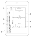
- FIG. 10 is a diagram showing an example of an operation screen when setting the image capture area in this embodiment.
- the operation screen 350 is displayed on the display unit 330 after screen data generated by the server 40 is transmitted to the control device 30.
- the screen 350 in FIG. 10 displays a line 360 (overall outline 360) showing the outline of the entire stadium 90, as well as a display 361 (candidate area display 361) showing the candidate image capture area.
- the screen 350 also displays multiple bidirectional arrows 362 for changing the range of the candidate area display 361, a guide message 363, and an approval button 364 for setting the candidate image capture area as the image capture area.
- a surrounding image may be displayed. In other words, these displays may be displayed in a format in which they are superimposed on the surrounding image.
- the user selects the approval button 364. This causes the server 40 to set the current candidate shooting area (in other words, the area corresponding to the candidate area display 361) as the target shooting area (S1016).
- the user operates the bidirectional arrow 362 to adjust the position of the candidate area display 361, and then selects the approval button 364 to set the target shooting area (S1017).
- the server 40 determines the area size of the shooting target area based on the information of the shooting target area set in step S1016 or S1017.
- the area size is defined by the area X ( m2 ) of the shooting target area.
- the area size may be defined by the length of the short side or the length of the long side of the shooting target area, or a combination of these.
- step S102 the server 40 (the flight condition setting unit 442 and the photographing condition setting unit 443 of the advance setting unit 440) sets flight conditions and photographing conditions according to the photographing target area set in step S101.
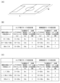
- FIG. 11 is a diagram showing an example of the relationship between the area of the area to be photographed in this embodiment and the flight conditions and photographing conditions in the overhead photographing mode and area flight mode.
- the range of the geofence in the vertical direction, the initial value of the target flight altitude of the drone 20 (initial target altitude), and the initial value of the zoom amount of the camera 231 (initial target zoom amount) are set according to the area X of the area to be photographed determined by the area size determination unit 444.
- the range of the geofence in the vertical direction and the initial target altitude are flight conditions
- the initial target zoom amount is a photographing condition.
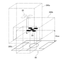
- FIG. 12 is a diagram showing an example of vertical and horizontal geofences 260a in the overhead shooting mode set in this embodiment, and vertical and horizontal geofences 260b in the area flight mode.
- FIG. 13 is a diagram showing the initial value of target flight altitude Htar1 in the overhead shooting mode set in this embodiment and the corresponding permitted flight area 92a, and the initial value of target flight altitude Htar2 in the area flight mode and the corresponding permitted flight area 92b. Both FIG. 12 and FIG. 13 show an example in which half of the stadium 90 is selected as the area to be shot.
- the area size determination unit 444 may determine the area X of the area to be photographed, for example, from the altitude Hd of the drone 20 when the peripheral image was acquired, the orientation of the camera 231, the zoom amount, etc. Alternatively, as described below, if a database related to the stadium 90 exists, the area size determination unit 444 may calculate the area X of the area to be photographed using basic data of the stadium 90 identified from the position of the drone 20 (this may include reading out the area X of the area to be photographed from the database).
- the flight geofence 260 (also referred to as "geofence 260") indicates a virtual boundary line, and in particular indicates a fence on the boundary line between a flight permitted area in which a mobile object such as the drone 20 is permitted to fly or move, and a no-fly area. Therefore, when a mobile object such as the drone 20 comes into contact with the geofence 260, the flight or movement is restricted so that the aircraft does not fly outside the flight permitted area.
- the geofence 260 is actually set as a three-dimensional area with height in addition to length and width (however, for control purposes, it may be managed as a two-dimensional area).
- the flight geofence, flight altitude (flight conditions), and zoom amount (photography conditions) set according to the area size (area) of the area to be photographed in accordance with the table shown in FIG. 11 may be displayed on the operation screen 350 as shown in FIG. 10, and changes to the flight conditions and photography conditions by the user may be accepted.
- multiple bidirectional arrows for changing the geofence 260, a guidance message, and an approval button for confirming the geofence are also displayed.
- a surrounding image may be displayed. In other words, these displays may be displayed in a format in which they are superimposed on the surrounding image.
- the aerial photography control (S20 in FIG. 7) is a control for performing aerial photography.
- the server 40 executes control (outward movement control) for moving the drone 20 from the flight position in the advance preparation flight mode to the photography start position (for example, the initial value of the target flight altitude Htar1 in the bird's-eye photography mode) of the photography target area (such as the stadium 90).
- step S202 the server 40 executes control (photography target area photography control (or aerial photography execution control)) for performing aerial photography of the photography target area by the drone 20 in the flight permission area defined by the geofence.
- step S203 the server 40 executes control (return movement control) for moving the drone 20 from the flight permission area to the target landing point.
- A-2-3-2. Outward Movement Control (S201 in FIG. 7)
- the drone 20 is moved from the flight position in the advance preparation flight mode to the shooting start position (a predetermined position in the sky) of the shooting target area (such as the stadium 90). Then, the drone 20 hovers at the shooting start position. At this time, the altitude of the drone 20 is adjusted to be within the range of the geofence in the vertical direction set in step S102. In addition, the zoom amount of the camera 231 is adjusted to the initial target zoom amount set in step S102.
- aerial photography execution control of this embodiment aerial photography is performed by the drone 20 in the photography target area.
- a mode selected by the user or the server 40 from among a plurality of photography flight modes is used.
- the photography flight mode an overhead photography mode, an area flight mode, etc. are used (details will be described later with reference to FIG. 14, etc.).
- the photography position of the drone 20 is selected by the user or the server 40 from a plurality of reference positions (photography reference positions) set in advance.
- the photography direction and zoom amount of the camera 231 are selected corresponding to each photography reference position. These will be described later with reference to FIG. 15 to FIG. 17.
- FIG. 14 is an explanatory diagram of the transition of flight modes in this embodiment.
- the flight modes used in this embodiment include an outside area takeoff and landing mode, a pre-preparation flight mode, an overhead photography mode, an inside area entry mode, an area flight mode, an outside area exit mode, and an inside area takeoff and landing mode.
- the pre-preparation flight mode is a flight mode used in the advance setting control (S10 in FIG. 7), particularly in the setting of the photography target area (S101).
- the outside area takeoff and landing mode is a flight mode used in steps S101 and S203 in FIG. 7. Therefore, the photography flight modes include an overhead photography mode, an inside area entry mode, an area flight mode, an outside area exit mode, and an inside area takeoff and landing mode.
- the overhead shooting mode is a flight mode when shooting an overhead image of the entire shooting target area from outside the shooting target area.
- the area flight mode is a flight mode when shooting a part of the shooting target area from inside the shooting target area.
- the area entry mode is a flight mode when switching from the overhead shooting mode to the area flight mode, and moves the drone 20 from the outside to the inside of the shooting target area.
- the area exit mode is a flight mode when switching from the area flight mode to the overhead shooting mode, and moves the drone 20 from the inside to the outside of the shooting target area.
- the area takeoff and landing mode is a flight mode when the drone 20 lands in the shooting target area or takes off from the shooting target area.
- the area takeoff and landing mode can be used, for example, when some abnormality occurs in the drone 20 or when severe weather conditions (strong winds, etc.) occur.
- each of the flight modes above also corresponds to the image capture control of the camera 231. Therefore, please note that each of the flight modes listed here may be referred to as a control mode of the camera 231.
- the shooting position of the drone 20 is selected from a plurality of preset reference positions (shooting reference positions) by the user or the server 40.
- the shooting direction and zoom amount of the camera 231 are basically selected corresponding to each shooting reference position.
- FIG. 15 is a diagram showing an example of the shooting reference positions of the drone 20 used in this embodiment.
- the shooting reference positions are shown as circled numbers 1 to 15.
- these shooting reference positions are also referred to as “shooting reference positions 1 to 15,” “reference positions 1 to 15,” or “positions 1 to 15.”
- each arrow corresponding to each position 1 to 15 indicates the pan (horizontal) direction of the camera 231 depending on its orientation, and indicates the tilt (vertical) direction of the camera 231 depending on its length. That is, a longer arrow indicates that the camera 231 is oriented closer to the horizontal direction, and a shorter arrow indicates that the camera 231 is oriented closer to the vertical direction.
- FIG. 15 the reference positions in FIG. 15 are used when the entire stadium 90 is set as the area to be photographed. Note that a case where half of the stadium 90 is set as the area to be photographed will be described later with reference to FIG. 17.
- reference positions 1 to 5 are located outside the stadium 90 (or touchline 901) and are used in the bird's-eye view shooting mode.
- Reference positions 6 to 15 are located inside the stadium 90 (or inside the two goal lines 900 and two touchlines 901) and are used in the area flight mode.
- reference position 1 (altitude zero) can be the takeoff and landing position of the drone 20.
- the target flight altitude Htar may be set for each position within the range of the geofence in the vertical direction.
- the target flight altitude Htar may be constant.
- the target flight altitude Htar, target zoom amount, etc. are adjusted so that the same or similar shooting range is obtained for each corresponding reference position when the entire stadium 90 is set as the shooting area and when half of the stadium 90 is set as the shooting area.
- These multiple reference positions 1 to 15 can be used as selectable positions for one drone 20.
- the user or the server 40 can select one of the reference positions for one drone 20.
- these reference positions can be used for simultaneous shooting by multiple drones 20.
- FIG. 16(A) is a diagram showing each image capture reference position when the entire stadium 90 is set as the image capture target area in this embodiment
- FIG. 16(B) is a diagram showing a simplified example of a screen displayed on the display unit 330 of the control device 30 corresponding to FIG. 16(A).
- FIG. 17(A) is a diagram showing each image capture reference position when half of the stadium 90 is set as the image capture target area in this embodiment
- FIG. 17(B) is a diagram showing a simplified example of a screen displayed on the display unit 330 of the control device 30 corresponding to FIG. 17(A).
- a screen 370a in FIG. 16(B) is a screen when an image is captured at the reference position 7 in FIG. 16(A).
- a screen 370b in FIG. 17(B) is a screen when an image is captured at the reference position 7 in FIG. 17(A).
- the target flight altitude Htar, target zoom amount, etc. are adjusted so as to obtain the same or similar shooting range.
- the target flight altitude Htar is lower and/or the target zoom amount (magnification factor) is smaller in the case of Figure 17(B) than in the case of Figure 16(B).
- the pan direction (horizontal direction) and tilt direction (vertical direction) of the camera 231 are basically the same in both the cases of Figures 16(B) and 17(B). However, the pan direction and/or tilt direction may be changed to bring the shooting range closer together.
- the target flight altitude Htar of the drone 20, the shooting direction (pan and tilt) of the camera 231, and the target value of the zoom amount are basically set to initial values for each of the shooting reference positions 1 to 15.
- the user of the control device 30 the viewer of the image captured by the drone 20
- FIG. 18(A) is a simplified diagram showing an example of a screen displayed on the display unit 330 of the control device 30 when the angle of view adjustment process is not performed in this embodiment
- FIG. 18(B) is a simplified diagram showing an example of a screen displayed on the display unit 330 of the control device 30 when the angle of view adjustment process is performed in this embodiment.
- athlete images 381a, 381b, and 381c are located at the bottom left of screen 380a, and no one is present in the top right of screen 380a. This may make it difficult to see the movements of each athlete image 381a, 381b, and 381c. Therefore, in the angle of view adjustment process, the angle of view of camera 231 is adjusted so that athlete images 381a, 381b, and 381c are displayed near the center of screen 380b.
- the angle of view adjustment process is performed as follows. That is, the server 40 processes the image acquired by the drone 20 and extracts each athlete image from the image.
- the athlete images can be extracted using existing technologies such as image binarization, feature point extraction, and pattern matching.
- the number of athlete images to be extracted is not limited to three. For example, all athlete images present in the image may be extracted.
- the server 40 then instructs the drone 20 to adjust the angle of view of the camera 231 so that the centroid of each detected athlete image is located at the center of the entire image. In Figures 18(A) and 18(B), the centroids are indicated by the symbol 382.
- centroid 382 may be calculated not only from the position of the athlete image, but also as the centroid of the athlete images 381a, 381b, and 381c and the ball image 383.
- the angle of view of the camera 231 may be adjusted so that the ball image 383 is located at the center of the entire image.
- the centroid 382 described above may be calculated as a two-dimensional centroid on the acquired image plane, or as a three-dimensional centroid on the actual stadium.
- the server 40 may detect lines (goal line 900, center line 902, touchline 901, etc.) that define the shooting area from the images acquired by the drone 20, distinguish between the players who are within the shooting area and other people who are outside the shooting area, and calculate the centroid 382 for the players only.
- the server 40 may distinguish between the players (players and substitute players) and other people by the color of their uniforms, and calculate the centroid 382 for the players only.
- geofences are set in both the vertical and horizontal directions (see, for example, FIG. 12 ). Separate geofences are set for each flight mode, such as the overhead photography mode and the area flight mode.
- FIG. 19 is a diagram showing geofences 260a, 260b, and 260c in the overhead shooting mode, area flight mode, and outside area takeoff and landing mode in this embodiment.
- the geofence 260a in the overhead shooting mode is a relatively narrow area in a planar view, but has a relatively wide range in the height direction.
- the geofence 260b in the area flight mode is a relatively wide area in a planar view, but has a relatively narrow range in the height direction. Note that the lower limit altitude Hlow is also shown for the geofence 260b.
- the geofence 260c in the outside area takeoff and landing mode is set at a position that covers the takeoff and landing point of the drone 20 and the area above it, and is a relatively narrow area in a planar view, similar to the geofence 260a.
- the mode when transitioning from the overhead shooting mode to the area flight mode, the mode is the inside area entry mode, and when transitioning from the area flight mode to the overhead shooting mode, the mode is the outside area exit mode (FIG. 14).
- the inside area entry mode and the outside area exit mode use a composite geofence that combines the geofences 260a and 260b of the overhead shooting mode and the area flight mode, respectively.
- a joint geofence that temporarily combines the geofences 260a and 260c is used. Note that, as shown in FIG.
- the area flight mode may be directly transitioned to the outside area takeoff and landing mode without going through the overhead shooting mode.
- a joint geofence is used that combines the area flight mode geofence 260b and the outside area takeoff and landing mode geofence 260c.
- the timing of switching the geofence when switching flight modes may be changed depending on the area size (magnitude) of the area to be photographed. For example, in each of the examples of Figures 16(A) and 17(A), when the drone 20 moves from reference position 1 to reference position 7, the geofence is smaller in the case of Figure 17(A) where the area to be photographed is smaller, so the drone 20 is more likely to collide with the geofence. Therefore, when the area to be photographed is small, the timing of making the composite geofence appear may be made earlier.
- a geofence in the vertical direction or a target flight altitude Htar is set for each flight mode.
- the drone control unit 240 executes flight stability control to temporarily lower the altitude (target flight altitude Htar) of the drone 20.
- Examples of such external environments include the occurrence of strong winds around the drone 20, a decrease in the reception strength of a signal (satellite signal) from the satellite 54, a state in which the number of artificial satellites 54 that receive satellite signals is lower than a predetermined number, or a state in which the elevation angle of the artificial satellite 54 that receives satellite signals is lower than a predetermined angle.
- the flight stability control may be executed by the flight control unit 450 instead of the drone control unit 240.
- step S301 the drone control unit 240 acquires the wind speed V of the anemometer 207 and the reception strength S of the satellite signal.
- step S302 the drone control unit 240 determines whether the wind speed V is smaller than the wind speed threshold THv. If the wind speed V is smaller than the wind speed threshold THv (S302: true), strong winds are not occurring in the external environment that affects the flight stability of the drone 20. Then, proceed to step S304. On the other hand, if the wind speed V is not smaller than the wind speed threshold THv (S302: false), strong winds are occurring.
- step S303 the drone control unit 240 temporarily lowers the target flight altitude Htar of the drone 20 (in that case, the drone may be landed within the shooting target area). Instead of the target flight altitude Htar, the upper limit flight altitude of the geofence may be temporarily lowered.
- step S304 the drone control unit 240 determines whether the reception strength S is greater than the strength threshold THs. If the reception strength S is greater than the strength threshold THs (S303: true), there is no decrease in the reception strength S due to the external environment that affects the flight stability of the drone 20. Therefore, the current flight stability control is terminated, and the process returns to step S301. On the other hand, if the reception strength S is not greater than the strength threshold THs (S303: false), a decrease in the reception strength S has occurred. Therefore, in step S305, the drone control unit 240 temporarily increases the target flight altitude Htar of the drone 20 in order to increase the reception strength S. Instead of the target flight altitude Htar, the lower limit flight altitude (and/or upper limit flight altitude) of the geofence may be temporarily increased.
- the satellite signal may be blocked and the strength (dB) of the satellite signal carrier may decrease, or the number of satellites 54 capable of receiving the satellite signal may decrease, or only satellites 54 with low elevation angles may exist as satellites 54 capable of receiving the satellite signal, which is undesirable from the viewpoint of ensuring flight stability. Therefore, in addition to the example shown in FIG. 20 in which the target flight altitude Htar is temporarily increased when the satellite signal reception strength S is smaller than the intensity threshold THs, instead of the satellite signal reception strength S, the target flight altitude Htar may be temporarily increased when the number of satellites 54 receiving the satellite signal falls below a predetermined number, or when the elevation angle of the satellite 54 receiving the satellite signal is lower than a predetermined angle.
- At least one of the flight conditions or the photographing conditions of the drone 20 (moving body) used by the calculation unit 420 (mobile body control device) of the server 40 during photographing is switched according to the area size (area X, etc.) of the photographing target area (FIG. 11). Therefore, even if the area size differs for each stadium 90, photographing according to the area size is possible. Furthermore, even when photographing the same stadium 90, it is possible to make the movement conditions or photographing conditions when the entire stadium 90 is used different from the movement conditions or photographing conditions when a part of the stadium 90 is used. Therefore, photographing according to the difference in the utilization area or the photographing target area in the stadium 90 is possible.
- the imaging target area setting unit 441 sets the imaging target area or the area size by distinguishing whether it is the whole or a part of one stadium 90 (for example, distinguishing between a full court and a half court) (FIGS. 10 and 11).
- the imaging target area setting unit 441 makes at least one of the flight conditions or imaging conditions of the drone 20 (moving body) during imaging different between when the imaging target area is the whole stadium 90 and when it is a part of the stadium 90 (FIGS. 11, 16(A) to 17(B)).
- the calculation unit 420 (mobile object control device) of the server 40 switches the target flight altitude Htar during shooting or the range of the geofence 260 in the vertical direction (area of permitted flight altitude) according to the area X (area size) of the area to be shot ( Figure 11). This makes it possible to precisely control the flight altitude H for each area X of the area to be shot in one stadium 90.
- the calculation unit 420 (mobile body control device) of the server 40 sets athlete images 381a, 381b, 381c as multiple objects of interest for the viewer of the image captured by the filming camera 231 (FIG. 18(B)).
- the calculation unit 420 also identifies the positions of the multiple athlete images 381a, 381b, 381c in the image captured by the filming camera 231, and calculates the centroid 382 from the positions of the multiple athlete images.
- the calculation unit 420 controls the angle of view of the filming camera 231 so that the centroid 382 is located in the center of the captured image (FIG. 18(B)). This makes it possible to adjust the angle of view so that the multiple athlete images 381a, 381b, 381c are easily visible to the viewer of the image captured by the filming camera 231.
- the calculation unit 420 (mobile body control device) of the server 40 switches the allowable range of the shooting direction or the target shooting direction during shooting according to the area X (area size) of the area to be shot (FIGS. 16(A) and 17(A)). This makes it possible to precisely control the shooting direction for each area X of the area to be shot.
- the calculation unit 420 (mobile body control device) of the server 40 switches the allowable range of the zoom amount during shooting or the target zoom amount according to the area X (area size) of the area to be shot (FIGS. 11, 16(A) and 17(A)). This makes it possible to precisely control the zoom amount for each area X of the area to be shot.
- the calculation unit 420 (mobile object control device) of the server 40 switches the area of the geofence 260 in the vertical or horizontal direction during shooting according to the area X (area size) of the area to be shot (FIGS. 11 and 12). This makes it possible to precisely set the geofence 260 for each area X of the area to be shot.
- the calculation unit 420 (mobile body control device) of the server 40 switches the range of permitted flight altitudes during shooting according to the area X (area size) of the area to be shot, and allows manual operation within the range of permitted flight altitudes (FIGS. 11 and 12). This allows manual operation of the flight altitude according to the area X of the area to be shot.
- the calculation unit 420 (mobile body control device) of the server 40 sets multiple flight modes for photography divided by the area in which the drone 20 (mobile body) can fly (Figure 14).
- the calculation unit 420 also sets geofences 260a, 260b, and 260c for each flight mode ( Figure 19).
- the calculation unit 420 switches the geofence switching timing when switching flight modes depending on the area X (area size) of the area to be photographed. This makes it possible to precisely set the switching timing of the flight geofence for each area X of the area to be photographed.
- the flight modes for photography can be switched between an overhead photography mode in which the entire photography target area is photographed from an overhead perspective, and an area flight mode (partial photography mode) in which only a portion of the photography target area is photographed ( Figure 14).
- the calculation unit 420 (mobile body control device) of the server 40 sets a joint geofence that combines the geofence used in the flight mode before the switch and the geofence used in the flight mode after the switch ( Figure 19). This enables smooth flight when switching flight modes.
- the imaging target area setting unit 441 detects candidates for the imaging target area based on the surrounding image acquired by the drone 20 (moving body) (S1013 in FIG. 8).
- the imaging target area setting unit 441 sets the imaging target area by having the user select or confirm the candidate imaging target area through an operation (S1015, S1016 in FIG. 8 and FIG. 10).
- the imaging target area (or imaging candidate area) detected when setting the imaging target area will completely match the imaging target area used when normal imaging is performed. Therefore, for example, if the user checks the detection result of the imaging target area (or imaging candidate area) when setting the imaging target area, it is possible to increase the reliability of the imaging target area during normal imaging.
- the calculation unit 420 (mobile object control device) of the server 40 changes the target flight altitude Htat, the upper limit flight altitude, or the lower limit flight altitude based on the wind speed V and the reception strength S (detection information of the external environment) (FIG. 20). This makes it possible to restrict the movement of the drone 20 and ensure flight stability when an external environment occurs that affects the flight stability of the drone 20.
- the detected information of the external environment is wind speed V. Furthermore, when wind speed V exceeds wind speed threshold THv (S302 in FIG. 20: false), the calculation unit 420 (mobile object control device) of the server 40 lowers the target flight altitude or the upper limit flight altitude (S303). As a result, in an environment where strong winds are occurring, it is possible to improve flight stability by lowering the flight altitude of the drone 20.
- the detection information of the external environment is the reception strength S of the satellite signal. If the reception strength S falls below the reception strength threshold THs (S304 in FIG. 20: false), the calculation unit 420 (mobile control device) of the server 40 increases the target flight altitude or the lower limit flight altitude (and/or the upper limit flight altitude) (S305). This makes it possible to change the flight state so as to increase the reception strength S of the satellite signal.
- the imaging system 10 of the above embodiment is intended to capture images of sports (soccer, baseball, tennis, etc.) taking place in a stadium 90 (FIG. 9, etc.).
- sports sports (soccer, baseball, tennis, etc.) taking place in a stadium 90 (FIG. 9, etc.).
- this is not limited to the above, if attention is paid to, for example, switching the movement conditions or imaging conditions of the drone 20 during imaging depending on the area size of the imaging target area, or setting not only the entire facility but also a part of it as the imaging target area.
- the imaging target is not limited to the above sports, and can also be applied to other events (exhibitions, concerts, ceremonies, etc.) where people gather.
- the photography system 10 had the configuration shown in FIG. 1.
- this is not limited to the above, for example, if attention is paid to the fact that the movement conditions or photography conditions of the drone 20 during photography can be switched depending on the area size of the area to be photographed, or that not only the entire facility but also part of it can be set as the area to be photographed.
- the drone 20 can be configured to wirelessly communicate directly with the Internet line 50 using a communication method such as LTE without going through the pilot device 30.
- a system redundancy configuration in which multiple servers 40 are connected to one or multiple drones 20 via multiple Internet lines 50 is also possible.
- the device described in the above embodiment may be realized as a single device, or may be realized by multiple devices (e.g., cloud server 40, drone 20, control device 30) partially or completely connected by a communication network 50.
- each functional unit and memory unit of server 40 may be realized by being implemented in different servers 40, drones 20, and control devices 30 that are connected to each other by the communication network 50.
- a drone 20 is used as an example of a mobile body for aerial photography, but this is not limited to the above, for example, if attention is paid to the fact that the movement conditions or photography conditions of the mobile body for photography can be switched depending on the area size of the area to be photographed, or that not only the entire facility but also a part of it can be set as the area to be photographed.
- the mobile body may be, for example, a camera system that can move along a wire placed in the air within the stadium 90.
- the mobile body may be a camera system (including one that moves on rails) that is placed on the ground and is movable.
- the control device 30 of the above embodiment has the configuration shown in Figures 4 and 5. However, this is not limited to the above, for example, if attention is paid to the fact that the movement conditions or shooting conditions of the drone 20 during shooting are switched according to the area size of the shooting target area, or that not only the entire facility but also a part of it can be set as the shooting target area.
- the operation input unit 320 for example, the number and arrangement of the input sticks, the number, shape and arrangement of the buttons can be appropriately changed.
- the configuration realized by the operation input unit 320 in Figure 5 can be replaced with a touch panel.
- the control input unit 320 may have a takeoff button and a landing button to instruct automatic takeoff and landing, a flight start button to instruct the drone to automatically fly to a specified position and hover there, a home button to perform a return operation to the starting position, a mode switch button to switch flight modes, etc.
- a computer program for realizing each function of the server 40 according to the present embodiment may be created and implemented in a PC or the like.
- a computer-readable recording medium in which such a computer program is stored may also be provided.
- the recording medium may be, for example, a magnetic disk, an optical disk, a magneto-optical disk, a flash memory, or the like.
- the above computer program may also be distributed, for example, via a communication network 50 without using a recording medium.
- the candidate shooting area was detected based on the surrounding image acquired by the drone 20 (S101 in FIG. 7, FIG. 8, FIG. 10).
- this is not limited to this, if attention is paid to the fact that the movement conditions or shooting conditions of the drone 20 during shooting can be switched according to the area size of the area to be shot, or that not only the entire facility but also a part of it can be set as the area to be shot.
- the target area for photography is set based on the candidate area for photography detected using the image acquired by the drone 20, whereas in the modified example in FIG. 21, the data of the candidate area for photography is stored in advance in a database (candidate area database) together with various information (e.g., the address, name, full court/half court, and position coordinates of the stadium 90).
- the candidate area database can be included in the storage unit 430 of the server 40, for example.
- the server 40 accepts the user's operation input for identifying the candidate area for photography stored in the candidate area DB via the control device 30 (step S1101).
- the server 40 reads out the candidate area for photography corresponding to the user's operation input from the candidate area DB and displays it on the display unit 330 of the control device 30 (step S1102).
- the server 40 sets the candidate area for photography selected by the user from among the candidate areas for photography as the target area for photography (step S1103).
- FIG. 22 is a simplified diagram showing an example of an operation screen when setting a photographing target area in the modified example of FIG. 21.
- the operation screen 390 is displayed on the display unit 330 after screen data generated by the server 40 is transmitted to the control device 30.
- an image 391 full-court image 391 showing the entirety (full court) of one playing field 90 is displayed.
- images 392a and 392b half-court images 392a and 392b showing half (half court) of one playing field 90 are displayed in the full-court image 391.
- the user selects either the full-court image 391, the half-court image 392a, or 392b by touch operation or the like.
- the half-court image 392b is selected, and is therefore highlighted by making the line thicker.
- the operation screen 390 can display a guidance message similar to the guidance message 363 in FIG. 10 and a button similar to the approval button 364. Therefore, the user can read the guidance message and understand the operations related to setting the area to be photographed. Then, with either the full-court image 391 or the half-court image 392a or 392b selected by touch operation or the like, the area to be photographed is set by pressing the approval button (not shown).
- the shooting target area setting unit 441 includes a candidate area DB that stores candidates for the shooting target area. Furthermore, the shooting target area setting unit 441 extracts candidates for the shooting target area that meet the user's specified conditions from the candidate area DB and sets them as the shooting target area (S1102, S1103 in FIG. 21). This makes it possible to easily set the shooting target area if the user has previously obtained information on the shooting candidate area that the user wants to use as the shooting target area.
- the area size determination unit 444 determines the area size by determining the area X of the shooting target area, or the length of the short side or the length of the long side if the shooting target area is rectangular, based on the information of the set shooting target area (for example, the position coordinates of the four corners of the court, etc.).
- the area X, etc. included in the candidate area DB may be used as the area size as is.
- FIG. 23(A) is a diagram showing the positions of the short side W and long side L when the area to be photographed is rectangular
- FIG. 23(B) is a diagram showing an example of the relationship between the short side W of the area to be photographed and the flight conditions and photographing conditions in the second modified example.
- the flight condition setting unit 442 and the photographing condition setting unit 443 set the range of the geofence in the vertical direction, the initial value of the target flight altitude of the drone 20 (initial target altitude), and the initial value of the zoom amount of the camera 231 (initial target zoom amount) according to the short side W of the area to be photographed.
- FIG. 23(C) is a diagram showing an example of the relationship between the long side L of the area to be photographed and the flight conditions and photographing conditions in the third modified example.
- the flight condition setting unit 442 and the photographing condition setting unit 443 set the range of the geofence in the vertical direction, the initial value of the target flight altitude of the drone 20 (initial target altitude), and the initial value of the zoom amount of the camera 231 (initial target zoom amount) according to the long side L of the area to be photographed.
- Figures 24(A) and 24(B) show an example of a method for setting flight conditions for the photographing reference position in the fourth modified example. That is, Figure 24(A) is a diagram showing the photographing reference position 6 etc. when the entire stadium 90a of the reference size is set as the photographing target area in the fourth modified example, and Figure 24(B) is a diagram showing the photographing reference position 6 etc. when the entire stadium 90b, which is larger than the reference size, is set as the photographing target area in the fourth modified example.
- the photographing reference positions 6 in Figures 24(A) and 24(B) each correspond to the photographing reference position 6 shown in Figure 15.
- FIG. 24(A) in addition to the photographing reference position 6 corresponding to the entire stadium 90a of the standard size, a target photographing point Ptar1 and a flight permission area 92c corresponding to the initial value of the target flight altitude Htar are shown.
- FIG. 24(B) in addition to the photographing reference position 6 corresponding to the entire stadium 90b, which is larger than the standard size, a target photographing point Ptar2 and a flight permission area 92d corresponding to the initial value of the target flight altitude Htar are shown.
- the photographing reference position 6 and target photographing point Ptar1 of FIG. 24(A) are shown by dashed lines, etc.
- the position coordinates of the shooting reference position 6 do not match in the stadiums 90a and 90b.
- the position coordinates of the shooting reference position 6 are changed according to the ratio of the area sizes of the stadiums 90a and 90b.
- the position coordinates of the shooting reference position are changed as follows.
- a target shooting point Ptar for example, Ptar1 in FIG. 24(A)
- the length of the virtual vector extending from it are preset for each shooting reference position (position 1 to position 15).
- the tip of the virtual vector becomes each shooting reference position.
- the area size determination unit 444 determines the area size of the area to be photographed (for example, the area size of the stadium 90b in FIG. 24(B)).
- the area size here can be, for example, the area X of the area to be photographed, or the length of the short side W, or the length of the long side L, or a combination of these.
- the pre-setting unit 440 then calculates the ratio between the area size of the current stadium 90b and the area size of the standard size stadium 90a.
- the pre-setting unit 440 adjusts the position of the target shooting point Ptar based on the calculated ratio (for example, Ptar1 ⁇ Ptar2).
- the pre-setting unit 440 also multiplies the length of the virtual vector of the reference size by the ratio to adjust or calculate the length of the virtual vector for the current stadium 90b.
- the tip of the adjusted virtual vector which has the adjusted position of the target shooting point Ptar as its starting point, is then set as the shooting reference position (horizontal position and altitude).
- the zoom amount can also be changed according to the ratio.
- the flight modes shown in FIG. 14 are given. However, this is not limited to the above, for example, if attention is paid to the fact that the movement conditions or shooting conditions of the drone 20 during shooting can be switched according to the area size of the area to be shot, or that not only the entire facility but also a part of it can be set as the area to be shot. For example, it is also possible to omit one or more of the flight modes in FIG. 14. Alternatively, it is also possible to use another shooting mode in addition to or instead of the flight modes in FIG. 14.
- the initial values of the shooting direction, zoom amount, etc. were set in advance for each reference position (camera position) of the drone 20 (in other words, for each position coordinate) (FIG. 15).
- a different method can be used if attention is paid to the fact that the movement conditions or shooting conditions of the drone 20 during shooting are switched according to the area size of the area to be shot, or that not only the entire facility but also a part of it can be set as the area to be shot.
- only the range of the geofence in the vertical direction may be set in advance, and the shooting direction, zoom amount, etc. may be freely adjustable by the user through manual operation.
- the angle of view adjustment process using the centroid 382 of the athlete images 381a, 381b, and 381b can be used (FIG. 18B).
- this is not limited to the above, for example, if the focus is on positioning an object of interest that is considered to be the center of interest for the user or viewer in a predetermined position (such as the center) of the screen in the image acquired by the drone 20.
- the angle of view may be adjusted according to the position or centroid of a specific one or more athletes (for example, a favorite member).
- Such an object of interest may be set not only by the administrator of the server 40, but also by the user (or viewer) of the control device 30.
- the movement conditions or shooting conditions of the drone 20 during shooting are switched according to the area size of the area to be shot, or if not only the entire facility but also part of it can be set as the area to be shot, it is possible to omit the angle of view adjustment process.
- the wind speed V and the satellite signal reception strength S are used to determine a situation in which the flight stability of the drone 20 may be reduced ( Figure 20).
- this is not limited to the above, for example, if attention is paid to determining a situation in which the flight stability of the drone 20 may be reduced.
- flight stability control can be performed using other external environments (for example, the amount of rainfall, the amount of snowfall).
- flight stability control can be omitted if attention is paid to switching the movement conditions or shooting conditions of the drone 20 during shooting depending on the area size of the shooting target area, or to being able to set not only the entire facility but also part of it as the shooting target area.
Landscapes
- Engineering & Computer Science (AREA)
- Multimedia (AREA)
- Signal Processing (AREA)
- Control Of Position, Course, Altitude, Or Attitude Of Moving Bodies (AREA)
Priority Applications (2)
| Application Number | Priority Date | Filing Date | Title |
|---|---|---|---|
| PCT/JP2023/007177 WO2024180639A1 (ja) | 2023-02-27 | 2023-02-27 | 撮影システム、撮影方法、移動体制御装置及びプログラム |
| JP2025503271A JPWO2024180639A1 (https=) | 2023-02-27 | 2023-02-27 |
Applications Claiming Priority (1)
| Application Number | Priority Date | Filing Date | Title |
|---|---|---|---|
| PCT/JP2023/007177 WO2024180639A1 (ja) | 2023-02-27 | 2023-02-27 | 撮影システム、撮影方法、移動体制御装置及びプログラム |
Publications (1)
| Publication Number | Publication Date |
|---|---|
| WO2024180639A1 true WO2024180639A1 (ja) | 2024-09-06 |
Family
ID=92589495
Family Applications (1)
| Application Number | Title | Priority Date | Filing Date |
|---|---|---|---|
| PCT/JP2023/007177 Ceased WO2024180639A1 (ja) | 2023-02-27 | 2023-02-27 | 撮影システム、撮影方法、移動体制御装置及びプログラム |
Country Status (2)
| Country | Link |
|---|---|
| JP (1) | JPWO2024180639A1 (https=) |
| WO (1) | WO2024180639A1 (https=) |
Citations (4)
| Publication number | Priority date | Publication date | Assignee | Title |
|---|---|---|---|---|
| JP2017103619A (ja) * | 2015-12-02 | 2017-06-08 | ソニー株式会社 | 制御装置、制御方法、およびプログラム |
| JP2019115012A (ja) * | 2017-12-26 | 2019-07-11 | エスゼット ディージェイアイ テクノロジー カンパニー リミテッドSz Dji Technology Co.,Ltd | 情報処理装置、飛行制御指示方法、プログラム、及び記録媒体 |
| JP2020166490A (ja) * | 2019-03-29 | 2020-10-08 | 大和ハウス工業株式会社 | 屋根の点検方法およびプログラム |
| WO2020262392A1 (ja) * | 2019-06-28 | 2020-12-30 | 富士フイルム株式会社 | 情報処理装置、情報処理方法、及びプログラム |
-
2023
- 2023-02-27 JP JP2025503271A patent/JPWO2024180639A1/ja active Pending
- 2023-02-27 WO PCT/JP2023/007177 patent/WO2024180639A1/ja not_active Ceased
Patent Citations (4)
| Publication number | Priority date | Publication date | Assignee | Title |
|---|---|---|---|---|
| JP2017103619A (ja) * | 2015-12-02 | 2017-06-08 | ソニー株式会社 | 制御装置、制御方法、およびプログラム |
| JP2019115012A (ja) * | 2017-12-26 | 2019-07-11 | エスゼット ディージェイアイ テクノロジー カンパニー リミテッドSz Dji Technology Co.,Ltd | 情報処理装置、飛行制御指示方法、プログラム、及び記録媒体 |
| JP2020166490A (ja) * | 2019-03-29 | 2020-10-08 | 大和ハウス工業株式会社 | 屋根の点検方法およびプログラム |
| WO2020262392A1 (ja) * | 2019-06-28 | 2020-12-30 | 富士フイルム株式会社 | 情報処理装置、情報処理方法、及びプログラム |
Also Published As
| Publication number | Publication date |
|---|---|
| JPWO2024180639A1 (https=) | 2024-09-06 |
Similar Documents
| Publication | Publication Date | Title |
|---|---|---|
| US11573562B2 (en) | Magic wand interface and other user interaction paradigms for a flying digital assistant | |
| US12498714B2 (en) | Systems and methods for UAV flight control | |
| US12276978B2 (en) | User interaction paradigms for a flying digital assistant | |
| KR101790592B1 (ko) | 관광드론을 이용한 증강현실 관광 시스템 및 방법 | |
| US12007763B2 (en) | Magic wand interface and other user interaction paradigms for a flying digital assistant | |
| CN114594792A (zh) | 用于控制可移动物体的设备和方法 | |
| US12122515B2 (en) | Systems and methods for controlling an unmanned aerial vehicle | |
| CN105391988A (zh) | 多视角的无人飞行器及其多视角显示方法 | |
| US20220368958A1 (en) | Live video distribution method using unmanned moving device, video distribution device used in live video distribution method, and video archive device for storing video data file generated by video distribution device | |
| WO2022141956A1 (zh) | 飞行控制方法、视频编辑方法、装置、无人机及存储介质 | |
| JP6688901B2 (ja) | 3次元形状推定方法、3次元形状推定システム、飛行体、プログラム、及び記録媒体 | |
| CN109997091A (zh) | 用于管理3d飞行路径的方法和相关系统 | |
| CN112987782A (zh) | 飞行控制方法和装置 | |
| JP2021113005A (ja) | 無人航空機システムおよび飛行制御方法 | |
| WO2022056683A1 (zh) | 视场确定方法、视场确定装置、视场确定系统和介质 | |
| JP7081198B2 (ja) | 撮影システム及び撮影制御装置 | |
| WO2024180639A1 (ja) | 撮影システム、撮影方法、移動体制御装置及びプログラム | |
| WO2024189898A1 (ja) | 撮影システム、撮影方法および撮影プログラム | |
| WO2024069790A1 (ja) | 空中撮影システム、空中撮影方法および空中撮影プログラム | |
| WO2023238208A1 (ja) | 空中撮影システム、空中撮影方法及び空中移動体管理装置 | |
| WO2024166318A1 (ja) | 撮影システム、撮影方法および撮影プログラム | |
| WO2024252444A1 (ja) | 判定システム、判定方法、及び判定プログラム | |
| WO2024069788A1 (ja) | 移動体システム、空中撮影システム、空中撮影方法および空中撮影プログラム | |
| WO2024018643A1 (ja) | 撮影システム、撮影方法、撮影制御装置及びプログラム | |
| JP7663990B2 (ja) | エリア設定システム、及びエリア設定方法 |
Legal Events
| Date | Code | Title | Description |
|---|---|---|---|
| 121 | Ep: the epo has been informed by wipo that ep was designated in this application |
Ref document number: 23925196 Country of ref document: EP Kind code of ref document: A1 |
|
| WWE | Wipo information: entry into national phase |
Ref document number: 2025503271 Country of ref document: JP |
|
| NENP | Non-entry into the national phase |
Ref country code: DE |
|
| 122 | Ep: pct application non-entry in european phase |
Ref document number: 23925196 Country of ref document: EP Kind code of ref document: A1 |