WO2024177102A1 - 光拡散装置 - Google Patents
光拡散装置 Download PDFInfo
- Publication number
- WO2024177102A1 WO2024177102A1 PCT/JP2024/006194 JP2024006194W WO2024177102A1 WO 2024177102 A1 WO2024177102 A1 WO 2024177102A1 JP 2024006194 W JP2024006194 W JP 2024006194W WO 2024177102 A1 WO2024177102 A1 WO 2024177102A1
- Authority
- WO
- WIPO (PCT)
- Prior art keywords
- light
- heat dissipation
- optical fiber
- diffusion device
- dissipation coating
- Prior art date
- Legal status (The legal status is an assumption and is not a legal conclusion. Google has not performed a legal analysis and makes no representation as to the accuracy of the status listed.)
- Ceased
Links
Images




Classifications
-
- A—HUMAN NECESSITIES
- A61—MEDICAL OR VETERINARY SCIENCE; HYGIENE
- A61B—DIAGNOSIS; SURGERY; IDENTIFICATION
- A61B18/00—Surgical instruments, devices or methods for transferring non-mechanical forms of energy to or from the body
- A61B18/18—Surgical instruments, devices or methods for transferring non-mechanical forms of energy to or from the body by applying electromagnetic radiation, e.g. microwaves
- A61B18/20—Surgical instruments, devices or methods for transferring non-mechanical forms of energy to or from the body by applying electromagnetic radiation, e.g. microwaves using laser
- A61B18/22—Surgical instruments, devices or methods for transferring non-mechanical forms of energy to or from the body by applying electromagnetic radiation, e.g. microwaves using laser the beam being directed along or through a flexible conduit, e.g. an optical fibre; Couplings or hand-pieces therefor
-
- A—HUMAN NECESSITIES
- A61—MEDICAL OR VETERINARY SCIENCE; HYGIENE
- A61N—ELECTROTHERAPY; MAGNETOTHERAPY; RADIATION THERAPY; ULTRASOUND THERAPY
- A61N5/00—Radiation therapy
- A61N5/06—Radiation therapy using light
- A61N5/0601—Apparatus for use inside the body
-
- A—HUMAN NECESSITIES
- A61—MEDICAL OR VETERINARY SCIENCE; HYGIENE
- A61B—DIAGNOSIS; SURGERY; IDENTIFICATION
- A61B18/00—Surgical instruments, devices or methods for transferring non-mechanical forms of energy to or from the body
- A61B18/18—Surgical instruments, devices or methods for transferring non-mechanical forms of energy to or from the body by applying electromagnetic radiation, e.g. microwaves
- A61B18/20—Surgical instruments, devices or methods for transferring non-mechanical forms of energy to or from the body by applying electromagnetic radiation, e.g. microwaves using laser
- A61B18/22—Surgical instruments, devices or methods for transferring non-mechanical forms of energy to or from the body by applying electromagnetic radiation, e.g. microwaves using laser the beam being directed along or through a flexible conduit, e.g. an optical fibre; Couplings or hand-pieces therefor
- A61B2018/2255—Optical elements at the distal end of probe tips
- A61B2018/2261—Optical elements at the distal end of probe tips with scattering, diffusion or dispersion of light
-
- A—HUMAN NECESSITIES
- A61—MEDICAL OR VETERINARY SCIENCE; HYGIENE
- A61N—ELECTROTHERAPY; MAGNETOTHERAPY; RADIATION THERAPY; ULTRASOUND THERAPY
- A61N5/00—Radiation therapy
- A61N2005/002—Cooling systems
- A61N2005/005—Cooling systems for cooling the radiator
-
- A—HUMAN NECESSITIES
- A61—MEDICAL OR VETERINARY SCIENCE; HYGIENE
- A61N—ELECTROTHERAPY; MAGNETOTHERAPY; RADIATION THERAPY; ULTRASOUND THERAPY
- A61N5/00—Radiation therapy
- A61N5/06—Radiation therapy using light
- A61N2005/063—Radiation therapy using light comprising light transmitting means, e.g. optical fibres
-
- G—PHYSICS
- G02—OPTICS
- G02B—OPTICAL ELEMENTS, SYSTEMS OR APPARATUS
- G02B6/00—Light guides; Structural details of arrangements comprising light guides and other optical elements, e.g. couplings
- G02B6/0001—Light guides; Structural details of arrangements comprising light guides and other optical elements, e.g. couplings specially adapted for lighting devices or systems
- G02B6/0005—Light guides; Structural details of arrangements comprising light guides and other optical elements, e.g. couplings specially adapted for lighting devices or systems the light guides being of the fibre type
- G02B6/0008—Light guides; Structural details of arrangements comprising light guides and other optical elements, e.g. couplings specially adapted for lighting devices or systems the light guides being of the fibre type the light being emitted at the end of the fibre
-
- G—PHYSICS
- G02—OPTICS
- G02B—OPTICAL ELEMENTS, SYSTEMS OR APPARATUS
- G02B6/00—Light guides; Structural details of arrangements comprising light guides and other optical elements, e.g. couplings
- G02B6/0001—Light guides; Structural details of arrangements comprising light guides and other optical elements, e.g. couplings specially adapted for lighting devices or systems
- G02B6/0005—Light guides; Structural details of arrangements comprising light guides and other optical elements, e.g. couplings specially adapted for lighting devices or systems the light guides being of the fibre type
- G02B6/001—Light guides; Structural details of arrangements comprising light guides and other optical elements, e.g. couplings specially adapted for lighting devices or systems the light guides being of the fibre type the light being emitted along at least a portion of the lateral surface of the fibre
Definitions
- the present invention relates to a light diffusion device for use in medical equipment.
- a conventional light diffusion device includes an optical fiber consisting of a core located at the center in the radial direction and a cladding located on the outer periphery of the core, and that emits laser light incident on the base end of the optical fiber from the tip end and the outer periphery on the tip side (see, for example, Patent Document 1).
- the optical fiber of the conventional light diffusion device has a light transmission section that transmits the laser light incident on the base end, and a light emission section at the tip side that emits the laser light transmitted through the light transmission section.
- the optical diffusion device is used in photoimmunotherapy, a cancer treatment method, by inserting the tip of an optical fiber into the human body and irradiating laser light onto a drug that has been administered to the human body and has reached the cancer cells.
- One of the objectives of the present invention is to provide a light diffusion device that can suppress heat generation at the light exit section and its vicinity.
- a light diffusing device is a light diffusing device comprising an optical fiber having a core located at a radial center side and a clad located on an outer peripheral side of the core, the light diffusing device causing light incident on a base end of the optical fiber to exit from a tip end side of the optical fiber, the optical fiber has a light transmitting section that transmits light incident from a base end portion toward a tip end portion, and a light emitting section that emits the light transmitted through the light transmitting section from an outer circumferential surface by removing a portion located on the outer circumferential side of the clad at the tip end side, a reflecting element that surrounds an outer peripheral surface of the light emitting portion, leaving a region that serves as a light emitting opening; a heat dissipation coating that contacts the reflecting element at a tip side and covers at least a part of the light transmitting portion; Equipped with.
- the thermal conductivity of the heat dissipation coating may be 80 W/m ⁇ K or more.
- the length of the heat dissipation coating may be equal to or greater than the thermal diffusion length.
- the heat dissipation coating may be metallic.
- the outer circumferential surface of the light emitting portion may be cylindrical.
- a region corresponding to the arc-shaped outer peripheral surface of the optical fiber with a predetermined central angle may be opened in a slit shape to serve as the light exit port.
- the tip of the optical fiber may have an end face that is oblique to a plane perpendicular to the axis of the core.
- the light reflectance of the reflective element may be 1% or more.
- the reflective element may be metal.
- the reflective element and the heat dissipation coating may be integrated.
- the reflective element may be a reflective resin.
- the reflective element may be ceramic.
- the heat dissipation coating may extend to the area in the axial direction where the light emitting portion is located, within the area in the circumferential direction where the reflecting element is located, on the tip side, and may be in radial contact with the reflecting element.
- the heat dissipation coating may be made of separate materials in the axial direction, with a region that covers at least a portion of the light transmission section and a region where the light emission section is present.
- the unevenness of the surface of the reflecting element facing the light emitting portion may be less than the wavelength of the light being used.
- the thermal conductivity of the heat dissipation coating may be 0.2 W/m ⁇ K or more.
- the heat dissipation coating may be tubular.
- FIG. 1 is a schematic diagram of a light diffusing device according to a first embodiment which is an exemplary aspect of the present invention.
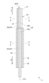
- 5 is a longitudinal sectional view of the light exit portion of an optical fiber in the light diffusing device according to the first embodiment and its vicinity, and is a sectional view taken along the CC section in FIGS. 3 and 4.
- FIG. 3 is a cross-sectional view of a portion of a light transmitting portion of an optical fiber in the light diffusing device according to the first embodiment, taken along the line BB in FIG. 2.
- 3 is a cross-sectional view of a portion of a light output portion of an optical fiber in the light diffusing device according to the first embodiment, taken along the line AA in FIG. 2.
- FIGS. 1A-1C are cross-sectional views of optical fibers illustrating variations in cladding removal at the outer surface of the optical fiber.
- 11 is a vertical cross-sectional view of a light exit portion of an optical fiber in a light diffusing device according to a second embodiment and its vicinity.
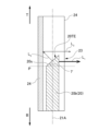
- FIG. 11 is an enlarged vertical cross-sectional view of a light exit portion of an optical fiber in a light diffusing device according to a second embodiment.
- FIG. 13 is a vertical cross-sectional view of a light exit portion of an optical fiber in a light diffusing device according to a third embodiment and its vicinity.
- FIG. 9 is a cross-sectional view of a portion of a light exit portion of an optical fiber in a light diffusing device according to a third embodiment, taken along the line FF in FIG. 8 .
- 1 is a graph for explaining the maximum height of a profile curve, the curve of the graph being an example of a roughness curve.
- 13A and 13B are schematic diagrams showing modified examples of
- Fig. 1 is a schematic diagram of a light diffusing device 1 according to a first embodiment
- Fig. 2 is a longitudinal sectional view of a light emitting portion of an optical fiber in the light diffusing device 1 and its vicinity
- Fig. 3 is a transverse sectional view of a portion of a light transmitting portion of an optical fiber in the light diffusing device 1
- Fig. 4 is a transverse sectional view of a portion of a light emitting portion of an optical fiber in the light diffusing device 1.
- the base end side of the optical fiber is indicated by an arrow B, and the tip side is indicated by an arrow T.
- FIG. 2 is a cross-sectional view taken along the line CC in FIG. 3 and FIG. 4
- FIG. 3 is a cross-sectional view taken along the line B-B in FIG. 2
- FIG. 4 is a cross-sectional view taken along the line A-A in FIG. 2.
- the light diffusion device 1 of this embodiment is used in photoimmunotherapy, which is one of the cancer treatment methods.
- Photoimmunotherapy is a procedure for treating cancer by administering to the human body a drug consisting of an antibody that binds to cancer cells and a substance that reacts to light, and then irradiating the drug that has bound to the cancer cells with laser light to destroy the cancer cells.
- the light diffusion device 1 is a device that emits light incident on the base end 20BE of the optical fiber 20 from the tip side T, and a laser oscillator 10 is connected to the base end 20BE on the base side B of the optical fiber 20 as a light source for generating laser light.
- the laser oscillator 10 has a semiconductor laser, and generates laser light by passing electricity through the semiconductor laser to cause laser oscillation.
- the laser oscillator 10 generates red laser light having a wavelength of 630 nm or more and 700 nm or less.
- the optical fiber 20 is made of a resin (plastic) member. As shown in Figures 3 to 5, the optical fiber 20 is a single-core optical fiber consisting of a core 21 located in the center in the radial direction and a cladding 22 located on the outer periphery of the core 21. The optical fiber 20 has a relative refractive index difference between the core 21 and the cladding 22 of 2% to 11%.
- the optical fiber 20 has, for example, an outer diameter of 500 ⁇ m, an outer diameter of the core 21 of 480 ⁇ m, and a thickness of the cladding 22 of 10 ⁇ m.
- the outer diameter of the cladding 22 of the optical fiber 20 is 102 ⁇ m or more and 1100 ⁇ m or less.
- the outer diameter of the core 21 of the optical fiber 20 is 100 ⁇ m or more and 1000 ⁇ m or less.
- the thickness of the cladding 22 is 1 ⁇ m or more and 50 ⁇ m or less.
- the optical fiber 20 has a light transmission section 20a that transmits the laser light incident from the base end 20BE toward the tip side T, and a light emission section 20b that causes the laser light transmitted through the light transmission section 20a to exit from the outer circumferential surface by removing a portion located on the outer circumferential side of the cladding 22 within a predetermined range in the extension direction of the tip side T.
- the tube 26 has a thickness of 0.1 mm, an outer diameter of 0.95 mm, and an inner diameter of 0.85 mm, but of course these sizes are not limited to these. It is also possible to use it without covering it with the tube 26 and leaving the heat dissipating coating 25 exposed.
- nylon is used as the material for the tube 26, but there are no particular limitations as long as it is a soft resin, and examples of the material that can be used in addition to nylon include polyvinyl chloride, vinylidene chloride, urethane resin, silicone resin, etc.
- the light emitting portion 20b that is not covered by the tube 26 is formed within a range of, for example, 10 mm to 100 mm, preferably 20 mm to 40 mm, on the tip side T of the optical fiber 20.
- the outer peripheral surface of the light emitting portion 20b has a cylindrical outer peripheral surface shape.
- the light emitting portion 20b is formed by removing a portion of the outer peripheral side of the clad 22 by, for example, blasting or etching, leaving the inner peripheral side in the thickness direction of the clad 22.
- the change in the structure of the optical fiber 20 in the longitudinal direction which is of the order of wavelength, changes the light intensity distribution in the cross section of the optical fiber 20, causing light to leak and laser light to be emitted from the outer peripheral surface.
- the cladding 22 is removed from the entire circumference of the optical fiber 20.
- the cladding 22 may be removed only from the outer surface of a circular arc in a certain region of the optical fiber 20 in the circumferential direction (central angle of 180° in Figure 5). In this case, the laser light is emitted from the outer surface of the region where the cladding 22 has been removed.
- the outer peripheral surface of the light emitting portion 20b is surrounded by a reflecting element 24, leaving only a small area.
- the area a corresponding to the arc-shaped outer peripheral surface of the optical fiber 20 with a predetermined central angle ⁇ is opened in a slit shape, and this opening becomes the light emitting port 23.
- the central angle ⁇ is set to, for example, 45°. There are no particular limitations on this central angle ⁇ , and it may be set appropriately depending on the purpose, desired performance, standards, etc., and is preferably selected from the range of 30° to 350°.
- the reflecting element 24 is a member that reflects light that leaks in a direction (area other than the area a corresponding to the light exit port 23) other than the light exit direction of the light exit section 20b (directions within the range of the central angle ⁇ ) in the circumferential direction, and causes the light to exit from the light exit port 23.
- the reflective element 24 has a light reflectance of 1% or more, preferably 30% or more, more preferably 50% or more, and more preferably 80% or more, and preferably close to 100%.
- the reflective element 24 has a thickness of 0.1 mm, an outer diameter of 0.8 mm, and an inner diameter of 0.6 mm, but of course the dimensions are not limited to these.
- the surface of the reflecting element 24 facing the light emitting portion 20b is as close to a mirror surface as possible in order to efficiently reflect the laser light.
- the unevenness of the surface of the reflecting element 24 facing the light emitting portion 20b is equal to or less than the wavelength of the light being used (laser light transmitted within the optical fiber 20).
- “unevenness” refers to the difference Rz between the peak of the maximum mountain and the bottom of the minimum valley of the unevenness as shown in Figure 10 (maximum height of the contour curve: see JIS B0601). Note that Figure 10 is a graph to explain the maximum height of the contour curve, and the curve in the graph is an example of a roughness curve.
- the reflective element 24 desirably has high thermal conductivity in view of the heat dissipation requirements described below.
- the thermal conductivity is preferably 0.2 W/m ⁇ K or more, more preferably 2 W/m ⁇ K or more, and even more preferably 16 W/m ⁇ K or more.
- the material of the reflective element 24 is not particularly limited as long as it has the desired light reflectance, but a material with high light reflectance is preferable.
- the material of the reflective element 24 include metals such as stainless steel, aluminum, gold, silver, copper, and nickel-titanium (Ni-Ti) alloy, fluororesins such as polytetrafluoroethylene (PTFE), resins containing barium sulfate, and reflective resins such as silicone resin, and ceramics such as alumina.
- the reflective element 24 is preferably made of metal, and is particularly preferably made of stainless steel.
- the reflective element 24 does not have to be manufactured from a single material. For example, a stainless steel cylinder is processed, the inside is mirror-polished, and then coated with a metal having a high reflectance, such as gold or silver, can be given as an example.
- the laser oscillator 10 when the laser oscillator 10 is operated to cause laser light to be incident on the base end 20BE of the optical fiber 20, the laser light is transmitted through the light transmission section 20a and emitted from the light emission section 20b.
- the laser light emitted radially in all directions in the circumferential direction from the light emission section 20b of the optical fiber 20 is partially emitted directly and the rest is reflected by the reflecting element 24 and emitted from the light emission port 23.
- the laser light transmitted through the light transmission section 20a is collected within a certain range in the circumferential direction by the light emission section 20b and is emitted from the side of the optical fiber 20. Therefore, the transmitted laser light can be efficiently irradiated onto the target to be irradiated, such as cancer cells.
- the practitioner is required to appropriately control the intensity and irradiation time of the laser light during treatment so that the temperature near the light emitting portion 20b does not become, for example, 5°C higher than the body temperature of the patient.
- the intensity of the laser light is relatively high; specifically, for example, an output of about 400 mW/cm is desirable.
- the continuous irradiation time of the laser light is a maximum of 5 minutes. Therefore, it is more desirable for the temperature near the light emitting part 20b to be less than 50°C at an output of 400 mW/cm x continuous irradiation time of 5 minutes.
- a heat dissipation coating 25 is provided to suppress heat generation in the light emitting portion 20b and its vicinity.
- the heat dissipation coating 25 is provided at the tip side TE, in contact with the reflecting element 24 and covering a part of the light transmitting portion 20a, so heat from the reflecting element 24 can be released and heat generation in the light emitting portion 20b and its vicinity can be suppressed.
- the heat dissipation coating 25 covers at least a portion of the light transmission section 20a.
- the heat dissipation coating 25 is flexible and tubular, into which the optical fiber 20 is inserted, and the outer periphery is further covered with the tube 26. That is, in the light diffusion device 1 of this embodiment, a certain region on the tip side T of the light transmission section 20a has a three-layer structure consisting of, in order from the center, the optical fiber 20, the heat dissipation coating 25, and the tube 26.
- the heat dissipation coating 25 is in contact with the reflecting element 24 at the tip side T.
- they may be fixed together with a fixing means such as adhesive, screws, or welding, or they may be molded into a shape that allows them to engage with each other and then engaged.
- the heat dissipation coating 25 and the reflective element 24 are molded as a single unit and are physically indistinguishable from each other (integrated), if the part that functions as the reflective element 24 and the part that functions as the heat dissipation coating 25 are separate and the parts that perform each function are connected at some point, the connected part is included in the concept of "contact" in this invention.
- the heat dissipation coating 25 comes into contact with the reflective element 24 and has the function of dissipating heat from the reflective element 24. For this reason, it is desirable for the heat dissipation coating 25 to have high thermal conductivity. Specifically, for example, the thermal conductivity of the heat dissipation coating 25 is preferably 80 W/m ⁇ K or more, more preferably 200 W/m ⁇ K or more, and even more preferably 350 W/m ⁇ K or more. Furthermore, it is desirable for the thermal conductivity of the reflective element 24 to be higher than that of the heat dissipation coating 25. In this embodiment, the heat dissipation coating 25 has a thickness of 0.1 mm, an outer diameter of 0.8 mm, and an inner diameter of 0.6 mm, but of course these sizes are not limited to these.
- the material of the heat dissipation coating 25 may be any material having the above-mentioned thermal conductivity.
- the material may be metals such as stainless steel, aluminum, gold, silver, copper, nickel-titanium (Ni-Ti) alloy, ceramics such as alumina, or resins such as silicone resin and polytetrafluoroethylene (PTFE) resin that have been processed to have heat dissipation properties.
- processing to have heat dissipation properties include processing in which metal particles or ceramic particles with high thermal conductivity (e.g. alumina particles) are dispersed in the material.
- the material of the heat dissipation coating 25 is the same as that of the reflecting element 24.
- the torque coil used to regulate the position (twist) of the optical fiber in the rotational direction may also function as the heat dissipation coating 25.
- the longitudinal region of the light transmitting section 20a covered by the heat dissipation coating 25 depends on the thermal conductivity of the heat dissipation coating 25.
- the thermal conductivity of the heat dissipation coating 25 is about 80 W/m ⁇ K, heat can be efficiently removed if the heat dissipation coating heat is equal to or greater than the thermal diffusion length at which 1/e is reached.
- the thermal conductivity of the heat dissipation coating 25 is 200 W/m ⁇ K or greater, the temperature near the light emitting section 20b can be kept at the desired temperature even if the length is about half the thermal diffusion length.
- the thermal diffusion length ⁇ is a physical property defined as an index of how far temperature can be transmitted.
- the amplitude of a temperature wave emitted from a certain point diffuses while exponentially decaying, and the thermal diffusion length ⁇ is the distance at which the amplitude of the temperature wave becomes 1/e.
- the thermal diffusion length ⁇ is defined as ⁇ ( ⁇ / ⁇ f) (where ⁇ is a physical property called thermal diffusivity).
- the thermal conductivity of the heat dissipation coating 25 is less than 80 W/m ⁇ K, it is preferable for the heat dissipation coating 25 to extend to an area located outside the body during treatment, as this area will come into contact with the outside air temperature and the heat dissipation effect will be enhanced.
- the heat dissipation coating 25 may cover the entire optical transmission section 20a up to the base end BE. More preferably, it is desirable to connect a heat sink for heat dissipation and actively dissipate heat from the heat sink.
- the heat sink for heat dissipation can be connected to the end of the base end side B of the heat dissipation coating 25 or near it, or halfway along the longitudinal direction. By actively releasing heat from the heat sink, the heat dissipation effect can be further improved. Examples of such a heat sink include a metal member with multiple plate-shaped protrusions for heat dissipation, or a metal lump with a volume sufficient to absorb the generated heat.
- the heat sink may be attached midway through the light transmission section 20a of the optical fiber 20, or may be disposed separately from the optical fiber 20.
- the end of the base end side B of the heat dissipation coating 25 or its vicinity, or midway in the longitudinal direction (axial direction) may be connected to the heat sink.
- the heat dissipation coating 25 may be branched off from the light transmission section 20a of the optical fiber 20 and connected to the heat sink.
- the tube 26 is not an essential component, so if there is no particular problem, the heat dissipation coating 25 may be exposed without the tube 26. However, in this embodiment, in order to protect the heat dissipation coating 25 and the optical fiber 20, the entire area of the optical fiber 20 that is located inside the body during treatment is covered in the longitudinal direction.
- the tip 20TE of the optical fiber 20 is left in the cut state, but a cap may be provided on the tip 20TE to prevent leakage of laser light from the tip 20TE and to protect the reflecting element 24 and the tip 20TE of the optical fiber 20.
- a cap may be provided on the tip 20TE to prevent leakage of laser light from the tip 20TE and to protect the reflecting element 24 and the tip 20TE of the optical fiber 20.
- materials for the cap include resins such as polytetrafluoroethylene (PTFE) and metals such as aluminum.
- the outer diameter of the optical fiber 20 in the light transmission section 20a, the inner and outer diameters of the heat dissipation coating 25, and the inner diameter of the tube 26 do not match each other, and there is a difference in diameter between each layer.
- This difference in diameter is a margin to ensure flexibility in the light transmission section 20a of the optical fiber 20 and to absorb tolerances during manufacturing, and is not intended to intentionally create gaps between each layer.
- Fig. 6 is a vertical cross-sectional view of a light output portion of an optical fiber in the light diffusing device 2 according to the second embodiment and its vicinity
- Fig. 7 is an enlarged vertical cross-sectional view of the light output portion. Since the light diffusing device 2 according to the present embodiment has a configuration substantially similar to that of the light diffusing device 1 according to the first embodiment, please refer to Fig. 1 for an outline of the light diffusing device 2.
- the D-D cross section in FIG. 6 is the same as FIG. 4, and the E-E cross section is the same as FIG. 3, so please refer to FIG. 3 and FIG. 4 for these cross sections.
- the light diffusion device 2 according to the second embodiment has the same configuration as the light diffusion device 1 according to the first embodiment, except that the shape of the tip portion 20TE of the optical fiber 20 is unique to this embodiment. Therefore, the members having the same functions as the light diffusion device 1 according to the first embodiment are given the same reference numerals as in FIG. 1 to FIG. 6, and their description will be omitted.
- the tip 20TE of the optical fiber 20 has an end face 20s that is inclined with respect to a plane P perpendicular to the axis 21A of the core 21.
- the angle ⁇ between the plane P and the end face 20s is set to be equal to or greater than the angle at which the laser light transmitted through the optical fiber 20 is totally reflected.
- the laser oscillator 10 when the laser oscillator 10 is operated to cause laser light to be incident on the base end 20BE of the optical fiber 20, the laser light is transmitted through the light transmitting section 20a and emitted from the light emitting section 20b.
- the tip end 20TE of the optical fiber 20 In the light emitting section 20b, the tip end 20TE of the optical fiber 20 has an end face 20s that is inclined with respect to the plane P perpendicular to the axis 21A of the core 21 as described above, and theoretically undergoes total reflection. The totally reflected laser light travels in the direction of the arrow L1 and is emitted from the light emitting port 23.
- the laser light transmitted through the light transmitting section 20a is collected within a certain range in the circumferential direction by the light emitting section 20b, including not only the totally reflected laser light L1 but also the laser light L2 leaking out from the end face 20s, and is emitted from the side of the optical fiber 20. Therefore, the transmitted laser light can be efficiently irradiated onto the target to be irradiated, such as cancer cells.
- the tip side TE also has a heat dissipation coating 25 that contacts the reflecting element 24 and covers part of the light transmission portion 20a, so that heat from the reflecting element 24 can be released and heat generation in and near the light exit portion 20b can be suppressed.
- Fig. 8 is a vertical cross-sectional view of the light output portion of an optical fiber in a light diffusing device 3 according to the third embodiment and its vicinity
- Fig. 9 is a horizontal cross-sectional view of the portion of the light output portion of an optical fiber in the light diffusing device 3.
- Fig. 9 is a cross-sectional view taken along the line F-F in Fig. 8. Since the light diffusing device 3 according to this embodiment has a configuration substantially similar to that of the light diffusing device 1 according to the first embodiment, refer to Fig. 1 for an overview of the light diffusing device 3.
- the cross section G-G in FIG. 8 is the same as that in FIG. 3, so please refer to FIG. 3 for this cross section.
- the light diffusion device 3 according to the third embodiment has the same configuration as the light diffusion device 1 according to the first embodiment, except for the structure in the vicinity of the light emission portion 20b of the optical fiber 20 which is unique to this embodiment. Therefore, the members having the same functions as the light diffusion device 1 according to the first embodiment are given the same reference numerals as in FIGS. 1 to 6, and their description will be omitted.
- a reflective resin is used as the reflective element 27 (hereinafter, referred to as "reflective resin 27").
- the reflective resin 27 include fluororesins such as polytetrafluoroethylene (PTFE), resins containing barium sulfate, silicone resins, etc.
- the heat dissipation coating 25 is composed of separate members in the axial direction, a member (heat dissipation coating main body 25a) for the area covering part of the light transmission section 20a, and a member (heat dissipation metal 25b) for the area where the light emitting section 20b is present.
- the heat dissipation coating main body 25a and the heat dissipation metal 25b are regarded as a single body that constitutes the heat dissipation coating 25, the heat dissipation coating 25 extends to the area where the light emitting section 20b is present in the axial direction 21A, within the range of the area where the reflecting element 24 is present in the circumferential direction, at the tip side TE, and is in radial contact with the reflective resin 27.
- the reflective resin 27 has a larger specific heat than the metallic reflective element 24 in the first and second embodiments, so the heat dissipation effect is ensured by making radial contact with the heat dissipation metal 25b to increase the contact area.
- the configuration of the heat dissipation coating body 25a is the same as the heat dissipation coating 25 in the first and second embodiments.
- the configuration of the heat dissipation metal 25b does not cover the entire circumference of the optical fiber 20, but is located only within the range of the area where the reflective resin (reflective element) 27 exists in the circumferential direction (range b in Figure 9).
- the material for the heat dissipation metal 25b is preferably one with the characteristics described as the material for the heat dissipation coating 25 in the first embodiment, and specific examples are similar. It is preferable that the heat dissipation coating body 25a and the heat dissipation metal 25b are made of the same material.
- heat dissipation metal 25b and the reflective resin 27 there are no particular limitations on the form of contact between the heat dissipation metal 25b and the reflective resin 27, so long as they are in physical contact. To ensure that the heat dissipation metal 25b and the reflective resin 27 are in contact with each other, they may be fixed together with adhesive, screws, welding, or other fixing means, or they may be molded into a shape that allows them to engage with each other and then engaged.
- heat dissipating metal 25b and the heat dissipating coating body 25a there are no particular limitations on the form between the heat dissipating metal 25b and the heat dissipating coating body 25a, as long as they are in physical contact. To ensure that the heat dissipating metal 25b and the heat dissipating coating body 25a are in contact, they may be fixed together with adhesive, screws, welding, or other fixing means, or they may be molded into a shape that allows them to engage with each other and then engaged.
- the heat dissipation metal 25b and the heat dissipation coating body 25a may be molded as a single unit, so that they are physically indistinguishable from each other. In this embodiment, whether they are integrated or separate, the heat dissipation metal 25b and the heat dissipation coating body 25a together constitute the heat dissipation coating 25.
- the laser oscillator 10 when the laser oscillator 10 is operated to cause laser light to be incident on the base end 20BE of the optical fiber 20, the laser light is transmitted through the light transmission section 20a and emitted from the light emission section 20b.
- the laser light emitted radially in all directions in the circumferential direction from the light emission section 20b of the optical fiber 20 is partially reflected directly and the rest is reflected by the reflective resin 27 and emitted from the light emission port 23.
- the laser light transmitted through the light transmission section 20a is collected within a certain range in the circumferential direction by the light emission section 20b and is emitted from the side of the optical fiber 20. Therefore, the transmitted laser light can be efficiently irradiated onto the target to be irradiated, such as cancer cells.
- the heat dissipation metal 25b contacts the reflective resin 27 in the radial direction, making it possible to increase the contact area and achieve a high heat dissipation effect.
- the heat dissipation metal 25b can also dissipate heat from the heat dissipation coating body 25a with which it is in contact, making it possible to suppress heat generation in and around the light emitting portion 20b.
- the configuration of this embodiment is also suitable for the case where ceramics, which has a larger specific heat than metal, is used as the reflecting element 24 .
- the modified examples and the materials of the respective members are similar to those of the first embodiment, and therefore the description thereof will be omitted.
- the shape of the light exit port is exemplified as a slit extending in the axial direction of the optical fiber (in a region corresponding to the arc-shaped outer circumferential surface of the optical fiber with a specified central angle), but is not limited to this.
- multiple perforations may be provided on the exit side surface of the reflecting element, and the perforations may serve as the light exit port.
- the shape of the perforations is also arbitrary, and may be circular, rectangular, or some other shape.
- a long and thin elliptical opening 28 may be provided on the exit side surface of the reflecting element 24' to form a window structure, which may serve as the light exit port 23'.
- FIG. 11 is a schematic diagram showing a modified example of the reflecting element. The shape of the opening of this window structure may also be appropriately selected, such as rectangular or polygonal.
- Specific specifications and conditions of the examples and comparative examples are as follows. Specifications and conditions not described below are as described in the explanation of the first embodiment.
- Test environment temperature Room temperature (22°C) Axial length of light emitting portion 20b: 40 mm Material of heat dissipation coating 25: SUS304 Material of the reflecting element 24: silicone resin, SUS304, aluminum, copper, silver Axial length of the heat dissipation coating 25 and the tube 26: 1 to 1000 mm Total length of optical fiber 20: 1040 mm State of the light emitting portion 20b when heated: held in air Room temperature during testing: 21° C. Wavelength of laser light from laser oscillator 10: 690 nm Laser light intensity of the laser oscillator 10: 550 mW
- the outer surface of the reflecting element 24 was measured with an infrared thermometer while the laser oscillator 10 was operated to cause laser light to enter the base end 20BE of the optical fiber 20 and emit (laser irradiation) from the light emitting portion 20b.
- the laser irradiation was continued for 5 minutes from the start, and the temperature of the outer surface of the reflecting element 24 was monitored.
- the evaluation criteria in Tables 1 to 3 are as follows. ⁇ : The temperature of the light emitting part and its vicinity is less than 40°C. ⁇ : The temperature of the light emitting part and its vicinity is 40°C or higher and lower than 50°C. ⁇ : The temperature of the light emitting part and its vicinity is 50°C or higher.
- thermal insulation coating material is aluminum, copper, or silver
- Example 11 and 12 where the heat dissipation coating was copper (thermal conductivity 386 W/mK), the temperature at the light emitting part and its vicinity was 31.4°C when the length (L3) of the heat dissipation coating was 40 mm for a thermal diffusion length of 106 mm. Furthermore, when the length (L3) of the heat dissipation coating was at the level of 100 mm, which is greater than the diffusion length, the temperature at the light emitting part and its vicinity was 22.0°C (the same temperature as room temperature), confirming a significant effect in suppressing temperature rise.
- Example 14 which was the same as Example 13 but also had a tip cap attached, the temperature at the light-emitting part and its vicinity dropped from 30.4°C to 26.9°C (-3.5°C), confirming a further effect in suppressing temperature rise.
- the light diffusion device of the embodiment which is provided with a metallic heat dissipation coating 25 with heat dissipation properties, was able to reduce the temperature of the light emitting section and its vicinity by 35% or more compared to the comparative example.
Landscapes
- Health & Medical Sciences (AREA)
- Life Sciences & Earth Sciences (AREA)
- Engineering & Computer Science (AREA)
- Biomedical Technology (AREA)
- Surgery (AREA)
- Physics & Mathematics (AREA)
- Nuclear Medicine, Radiotherapy & Molecular Imaging (AREA)
- Animal Behavior & Ethology (AREA)
- General Health & Medical Sciences (AREA)
- Public Health (AREA)
- Veterinary Medicine (AREA)
- Electromagnetism (AREA)
- Optics & Photonics (AREA)
- Radiology & Medical Imaging (AREA)
- Otolaryngology (AREA)
- Pathology (AREA)
- Heart & Thoracic Surgery (AREA)
- Medical Informatics (AREA)
- Molecular Biology (AREA)
- Optical Couplings Of Light Guides (AREA)
- Light Guides In General And Applications Therefor (AREA)
Priority Applications (3)
| Application Number | Priority Date | Filing Date | Title |
|---|---|---|---|
| DE112024000951.4T DE112024000951T5 (de) | 2023-02-21 | 2024-02-21 | Lichtstreuungsvorrichtung |
| CN202480014060.0A CN120731113A (zh) | 2023-02-21 | 2024-02-21 | 光扩散装置 |
| JP2025502765A JPWO2024177102A1 (https=) | 2023-02-21 | 2024-02-21 |
Applications Claiming Priority (2)
| Application Number | Priority Date | Filing Date | Title |
|---|---|---|---|
| JP2023025403 | 2023-02-21 | ||
| JP2023-025403 | 2023-02-21 |
Publications (1)
| Publication Number | Publication Date |
|---|---|
| WO2024177102A1 true WO2024177102A1 (ja) | 2024-08-29 |
Family
ID=92501347
Family Applications (1)
| Application Number | Title | Priority Date | Filing Date |
|---|---|---|---|
| PCT/JP2024/006194 Ceased WO2024177102A1 (ja) | 2023-02-21 | 2024-02-21 | 光拡散装置 |
Country Status (4)
| Country | Link |
|---|---|
| JP (1) | JPWO2024177102A1 (https=) |
| CN (1) | CN120731113A (https=) |
| DE (1) | DE112024000951T5 (https=) |
| WO (1) | WO2024177102A1 (https=) |
Citations (3)
| Publication number | Priority date | Publication date | Assignee | Title |
|---|---|---|---|---|
| US5814041A (en) * | 1992-03-20 | 1998-09-29 | The General Hospital Corporation | Laser illuminator |
| JP2006253099A (ja) * | 2005-02-08 | 2006-09-21 | Nichia Chem Ind Ltd | 発光装置 |
| WO2022118559A1 (ja) * | 2020-12-01 | 2022-06-09 | 株式会社カネカ | 光照射医療装置 |
-
2024
- 2024-02-21 JP JP2025502765A patent/JPWO2024177102A1/ja active Pending
- 2024-02-21 DE DE112024000951.4T patent/DE112024000951T5/de active Pending
- 2024-02-21 WO PCT/JP2024/006194 patent/WO2024177102A1/ja not_active Ceased
- 2024-02-21 CN CN202480014060.0A patent/CN120731113A/zh active Pending
Patent Citations (3)
| Publication number | Priority date | Publication date | Assignee | Title |
|---|---|---|---|---|
| US5814041A (en) * | 1992-03-20 | 1998-09-29 | The General Hospital Corporation | Laser illuminator |
| JP2006253099A (ja) * | 2005-02-08 | 2006-09-21 | Nichia Chem Ind Ltd | 発光装置 |
| WO2022118559A1 (ja) * | 2020-12-01 | 2022-06-09 | 株式会社カネカ | 光照射医療装置 |
Also Published As
| Publication number | Publication date |
|---|---|
| JPWO2024177102A1 (https=) | 2024-08-29 |
| CN120731113A (zh) | 2025-09-30 |
| DE112024000951T5 (de) | 2025-12-31 |
Similar Documents
| Publication | Publication Date | Title |
|---|---|---|
| CN105659133B (zh) | 光电子组件 | |
| US5373571A (en) | Fiber optic diffuser tip | |
| CN205339870U (zh) | 改进的紫外线应用装置 | |
| US20090210038A1 (en) | Medical Light Diffusers for High Power Applications and their Manufacture | |
| CN103562623B (zh) | 光源装置 | |
| CN102109099A (zh) | 照明装置 | |
| AU2018297141B2 (en) | Light diffusing devices for use in photoimmunotherapy | |
| US11561337B2 (en) | Luminaire having a light guide with cladding | |
| JP7292301B2 (ja) | 体組織治療装置及び該装置の製造方法 | |
| JP5634866B2 (ja) | 光ファイバーコンタクト | |
| WO2024177102A1 (ja) | 光拡散装置 | |
| US10018784B2 (en) | Fiber-optic device and process for manufacturing the device | |
| JP7210377B2 (ja) | 医療用レーザライトガイド | |
| JP2023131102A (ja) | 周面発光線状導光体 | |
| JP6775394B2 (ja) | 光コネクタ構造 | |
| WO2024204739A1 (ja) | カテーテル、並びにこれを備えるカテーテルセット及び光拡散装置 | |
| JP2008220435A (ja) | 光照射ファイバ | |
| WO2024203845A1 (ja) | 光拡散装置 | |
| WO2024204385A1 (ja) | 光拡散装置 | |
| JP2019051022A (ja) | 光散乱部品及び医療ライトガイド | |
| JP7053547B2 (ja) | 医療用ライトガイド及びその製造方法 | |
| US20250262452A1 (en) | Light diffusion device | |
| JP6192322B2 (ja) | 照明装置 | |
| JP7750141B2 (ja) | 周面発光線状導光体及びその製造方法 | |
| WO2024101288A1 (ja) | 光拡散装置 |
Legal Events
| Date | Code | Title | Description |
|---|---|---|---|
| 121 | Ep: the epo has been informed by wipo that ep was designated in this application |
Ref document number: 24760400 Country of ref document: EP Kind code of ref document: A1 |
|
| ENP | Entry into the national phase |
Ref document number: 2025502765 Country of ref document: JP Kind code of ref document: A |
|
| WWE | Wipo information: entry into national phase |
Ref document number: 2025502765 Country of ref document: JP |
|
| WWE | Wipo information: entry into national phase |
Ref document number: 202480014060.0 Country of ref document: CN |
|
| WWE | Wipo information: entry into national phase |
Ref document number: 112024000951 Country of ref document: DE |
|
| WWP | Wipo information: published in national office |
Ref document number: 202480014060.0 Country of ref document: CN |
|
| WWP | Wipo information: published in national office |
Ref document number: 112024000951 Country of ref document: DE |
|
| 122 | Ep: pct application non-entry in european phase |
Ref document number: 24760400 Country of ref document: EP Kind code of ref document: A1 |