WO2024177015A1 - TiNi系合金およびそれを含む蓄熱装置、ならびにそのTiNi系合金の製造方法 - Google Patents
TiNi系合金およびそれを含む蓄熱装置、ならびにそのTiNi系合金の製造方法 Download PDFInfo
- Publication number
- WO2024177015A1 WO2024177015A1 PCT/JP2024/005809 JP2024005809W WO2024177015A1 WO 2024177015 A1 WO2024177015 A1 WO 2024177015A1 JP 2024005809 W JP2024005809 W JP 2024005809W WO 2024177015 A1 WO2024177015 A1 WO 2024177015A1
- Authority
- WO
- WIPO (PCT)
- Prior art keywords
- tini
- alloy
- temperature
- based alloy
- point
- Prior art date
- Legal status (The legal status is an assumption and is not a legal conclusion. Google has not performed a legal analysis and makes no representation as to the accuracy of the status listed.)
- Ceased
Links
Images


Classifications
-
- C—CHEMISTRY; METALLURGY
- C09—DYES; PAINTS; POLISHES; NATURAL RESINS; ADHESIVES; COMPOSITIONS NOT OTHERWISE PROVIDED FOR; APPLICATIONS OF MATERIALS NOT OTHERWISE PROVIDED FOR
- C09K—MATERIALS FOR MISCELLANEOUS APPLICATIONS, NOT PROVIDED FOR ELSEWHERE
- C09K5/00—Heat-transfer, heat-exchange or heat-storage materials, e.g. refrigerants; Materials for the production of heat or cold by chemical reactions other than by combustion
- C09K5/08—Materials not undergoing a change of physical state when used
-
- C—CHEMISTRY; METALLURGY
- C22—METALLURGY; FERROUS OR NON-FERROUS ALLOYS; TREATMENT OF ALLOYS OR NON-FERROUS METALS
- C22C—ALLOYS
- C22C14/00—Alloys based on titanium
-
- C—CHEMISTRY; METALLURGY
- C22—METALLURGY; FERROUS OR NON-FERROUS ALLOYS; TREATMENT OF ALLOYS OR NON-FERROUS METALS
- C22C—ALLOYS
- C22C19/00—Alloys based on nickel or cobalt
- C22C19/03—Alloys based on nickel or cobalt based on nickel
-
- C—CHEMISTRY; METALLURGY
- C22—METALLURGY; FERROUS OR NON-FERROUS ALLOYS; TREATMENT OF ALLOYS OR NON-FERROUS METALS
- C22C—ALLOYS
- C22C30/00—Alloys containing less than 50% by weight of each constituent
-
- C—CHEMISTRY; METALLURGY
- C22—METALLURGY; FERROUS OR NON-FERROUS ALLOYS; TREATMENT OF ALLOYS OR NON-FERROUS METALS
- C22C—ALLOYS
- C22C30/00—Alloys containing less than 50% by weight of each constituent
- C22C30/02—Alloys containing less than 50% by weight of each constituent containing copper
-
- C—CHEMISTRY; METALLURGY
- C22—METALLURGY; FERROUS OR NON-FERROUS ALLOYS; TREATMENT OF ALLOYS OR NON-FERROUS METALS
- C22F—CHANGING THE PHYSICAL STRUCTURE OF NON-FERROUS METALS AND NON-FERROUS ALLOYS
- C22F1/00—Changing the physical structure of non-ferrous metals or alloys by heat treatment or by hot or cold working
- C22F1/10—Changing the physical structure of non-ferrous metals or alloys by heat treatment or by hot or cold working of nickel or cobalt or alloys based thereon
-
- C—CHEMISTRY; METALLURGY
- C22—METALLURGY; FERROUS OR NON-FERROUS ALLOYS; TREATMENT OF ALLOYS OR NON-FERROUS METALS
- C22F—CHANGING THE PHYSICAL STRUCTURE OF NON-FERROUS METALS AND NON-FERROUS ALLOYS
- C22F1/00—Changing the physical structure of non-ferrous metals or alloys by heat treatment or by hot or cold working
- C22F1/16—Changing the physical structure of non-ferrous metals or alloys by heat treatment or by hot or cold working of other metals or alloys based thereon
- C22F1/18—High-melting or refractory metals or alloys based thereon
- C22F1/183—High-melting or refractory metals or alloys based thereon of titanium or alloys based thereon
-
- Y—GENERAL TAGGING OF NEW TECHNOLOGICAL DEVELOPMENTS; GENERAL TAGGING OF CROSS-SECTIONAL TECHNOLOGIES SPANNING OVER SEVERAL SECTIONS OF THE IPC; TECHNICAL SUBJECTS COVERED BY FORMER USPC CROSS-REFERENCE ART COLLECTIONS [XRACs] AND DIGESTS
- Y02—TECHNOLOGIES OR APPLICATIONS FOR MITIGATION OR ADAPTATION AGAINST CLIMATE CHANGE
- Y02E—REDUCTION OF GREENHOUSE GAS [GHG] EMISSIONS, RELATED TO ENERGY GENERATION, TRANSMISSION OR DISTRIBUTION
- Y02E60/00—Enabling technologies; Technologies with a potential or indirect contribution to GHG emissions mitigation
- Y02E60/14—Thermal energy storage
Definitions
- This disclosure relates to a TiNi-based alloy and a heat storage device containing the same, as well as a method for producing the TiNi-based alloy.
- heat storage materials that store excess heat inside the material and can be freely released and used when needed are being developed. In developing heat storage materials, it is generally considered to utilize the heat absorption and generation that accompanies the phase transformation of the material.
- heat storage materials such as water or paraffin
- heat storage materials generally utilize the heat of transformation that occurs when the material changes from solid to liquid.
- Such materials have a very large heat of transformation per volume (e.g., 200 J/cc or more).
- the thermal conductivity of this material is very low, at about 1 W/mK, making it difficult to efficiently take in heat inside the material and difficult to dissipate heat to the outside of the material.
- it is difficult to maintain a fixed shape of this material as it is necessary to encapsulate the liquid, and the shape is limited to simple ones.
- the capsule acts as a heat barrier and reduces the properties as a heat storage material.
- oxide ceramics such as Ti 2 O 3 and VO 2 show a solid (low temperature phase)-solid (high temperature phase) phase transformation. Furthermore, the heat of transformation is about 200-250 J/cc, which is comparable to the heat of transformation associated with the above-mentioned solid-liquid.
- oxide ceramics such as Ti 2 O 3 and VO 2 show a solid (low temperature phase)-solid (high temperature phase) phase transformation.
- the heat of transformation is about 200-250 J/cc, which is comparable to the heat of transformation associated with the above-mentioned solid-liquid.
- Ti 2 O 3 what was in the high temperature phase at 1 atmosphere is transformed into the low temperature phase by increasing the pressure to a very high hydrostatic pressure of 300 atmospheres, and heat can be released to the outside of the material with this phase transformation.
- a low temperature phase is also generated by applying a large impact with a hammer, etc., and heat can also be released with this.
- this material also has a very low thermal conductivity of about 1 W/mK, making it difficult to efficiently take in heat inside the material.
- this material has poor ductility and workability, making it difficult to process into complex shapes.
- this material is brittle, so it is easily broken when high pressure and large impact are applied to induce the low-temperature phase as described above.
- Non-Patent Document 2 discloses the use of TiNi-based alloys that exhibit martensitic transformation as a solid-solid phase change.
- the end temperature (Af point) of transformation to the high-temperature phase (austenite phase) during heating is the end temperature of heat absorption
- the start temperature (Ms point) of transformation to the low-temperature phase (martensite phase) during cooling is the start temperature of heat dissipation.
- the TiNi-based alloy can store heat in the temperature range from the Ms point to the Af point.
- TiNi-based alloys can generate a high phase transformation heat of up to about 230 J/cc, and furthermore, a relatively small stress can induce transformation from the high-temperature phase to the low-temperature phase, which can dissipate heat.
- the phase transformation heat is controlled by controlling the component composition of the TiNi alloy.
- the phase transformation temperature e.g., the Ms point, which is the heat dissipation start temperature
- the phase transformation heat and the phase transformation temperature are separately.
- This disclosure has been made in light of these circumstances, and one of its objectives is to provide a TiNi-based alloy in which the phase transformation heat and phase transformation temperature can be controlled separately, another objective is to provide a heat storage device including the TiNi-based alloy, and yet another objective is to provide a method for producing the TiNi-based alloy.
- Aspect 1 of the present invention is The TiNi-based alloy has a martensitic transformation start temperature (Ms point) and satisfies the following formula (1).
- ⁇ 2°C...(1) Ms is the Ms point (°C) of the alloy measured according to JIS H7101:2002
- Ms 900° C is the Ms point (°C) of the alloy measured according to JIS H7101:2002 after heating the alloy at 900°C for 1 hour.
- Aspect 2 of the present invention is The TiNi-based alloy according to aspect 1, further satisfying the following formula (2): (Af-Ms)-(Af 900°C -Ms 900°C ) ⁇ 2°C...(2)
- Af is the austenite phase transformation finish temperature (Af point) (°C) of the alloy measured according to JIS H7101:2002
- Af 900°C is the Af point (°C) of the alloy measured according to JIS H7101:2002 after heating the alloy at 900°C for 1 hour.
- Aspect 3 of the present invention is The TiNi-based alloy according to embodiment 1 or 2 has a component composition represented by the following formula (3).
- x is the molar ratio (%) of Ti to the total number of moles of Ti, Ni, and M in the alloy and satisfies 35 ⁇ x ⁇ 55
- y is the molar ratio (%) of M to the total number of moles of Ti, Ni, and M in the alloy and satisfies 0 ⁇ y ⁇ 20
- M is one or more selected from the group consisting of Cu, Co, Cr, Zr, and Fe.
- Aspect 4 of the present invention is A TiNi-based alloy according to any one of Aspects 1 to 3, wherein the crystallite size is 30 nm or less.
- Aspect 5 of the present invention is The TiNi-based alloy according to any one of Aspects 1 to 4, which is capable of absorbing heat by heating to a temperature equal to or higher than the Af point and then dissipating heat by application of an external stress.
- Aspect 6 of the present invention is The TiNi-based alloy according to any one of Aspects 1 to 5, which is in the form of a plate, wire or spring.
- Aspect 7 of the present invention is A TiNi-based alloy according to any one of aspects 1 to 6;
- a heating unit capable of heating the TiNi-based alloy to a temperature equal to or higher than the austenite phase transformation finish temperature (Af point) of the TiNi-based alloy and lower than 200° C., and capable of maintaining the temperature at a temperature between the martensite transformation start temperature (Ms point) and the austenite phase transformation finish temperature (Af point) of the TiNi-based alloy;
- a heat storage device comprising:
- Aspect 8 of the present invention is A step of processing a TiNi-based alloy material having a martensitic transformation start temperature (Ms point) at a cross-sectional area change rate of 20% or more; Heating the processed TiNi-based alloy material to 200 to 800 ° C.; A method for producing the TiNi-based alloy according to any one of aspects 1 to 6, comprising:
- a TiNi-based alloy in which the phase transformation heat and phase transformation temperature can be controlled separately, a heat storage device including the same, and a method for manufacturing the TiNi-based alloy.
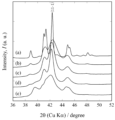
- Test Nos. 1 to 5 shows X-ray diffraction patterns of Test Nos. 1 to 5.
- 1 is a graph showing temperature changes during a four-point bending test of Test No. 5.
- 1 is a graph showing temperature changes during a tensile test of Test No. 4.
- 1 is a graph showing temperature changes during a tensile test of Test No. 5.
- Photograph of Test No. 16. 1 is a graph showing temperature changes when tensile deformation is performed for Test No. 16.
- 1 is a graph showing a temperature change when compressive deformation is performed for Test No. 16.
- the present inventors have studied from various angles in order to realize a TiNi-based alloy in which the phase transformation heat and the phase transformation temperature can be controlled individually. As a result, it has been found that a TiNi-based alloy having a phase transformation temperature different from the phase transformation temperature that can be normally shown based on a predetermined component composition can be realized by performing a predetermined process on a TiNi-based alloy showing a predetermined Ms point, and adjusting the amount of the defects by heating.
- the difference between the Ms point changed by the strain applied by the predetermined process or the like and the Ms point after heating at a high temperature (900 ° C.) for 1 hour to remove the strain is 2 ° C. or more.
- ⁇ 2 ° C. means that the TiNi alloy according to the embodiment of the present invention has been subjected to a predetermined process or the like and strain has been applied. The following provides details of each requirement stipulated by the embodiment of the present invention.
- the TiNi-based alloy according to the embodiment of the present invention is a TiNi-based alloy that has a martensitic transformation start temperature (Ms point) and satisfies the following formula (1).
- ⁇ 2°C...(1) Ms is the Ms point (°C) of the alloy measured according to JIS H7101:2002
- Ms 900°C is the Ms point (°C) of the alloy measured according to JIS H7101:2002 after heating the alloy at 900°C for 1 hour.
- Ms 900°C is the Ms point after heating to remove strain applied by a specific processing or the like described below, and can be a temperature equivalent to the Ms point before the specific processing or the like described below is applied.
- the TiNi alloy can be used in a wide range of applications as a heat storage material, since the phase transformation heat and the phase transformation temperature can be controlled separately (i.e., the phase transformation heat is controlled mainly by the composition, and the phase transformation temperature is controlled mainly by a predetermined processing (strain)).
- the left side of the formula (1) is 4°C or more, and more preferably, the left side of the formula (1) is 6°C or more.
- the TiNi alloy can store heat within a temperature range of, for example, the Ms point to the Af point. Therefore, the TiNi alloy according to the embodiment of the present invention preferably has a large difference between the Af point and the Ms point so as to widen the temperature range in which heat can be stored.
- the difference between the Af point and the Ms point is usually determined by the composition of the components, but in the embodiment of the present invention, it can be controlled by a predetermined processing (and heat treatment) described later.
- the TiNi alloy according to the embodiment of the present invention preferably satisfies the following formula (2).
- Af is the Af point (°C) of the alloy measured according to JIS H7101:2002
- Af 900°C is the Af point (°C) of the alloy measured according to JIS H7101:2002 after heating the alloy at 900°C for 1 hour.
- Af 900°C is the Af point after heating to remove strain applied by a predetermined processing or the like described below, and can be the same temperature as the Af point before the predetermined processing or the like described below is applied.
- the material can be used in a wider range of applications as a heat storage material.
- the left side of the above formula (2) is 4° C. or more, and more preferably, the left side of the above formula (2) is 5° C. or more.
- the TiNi-based alloy according to the embodiment of the present invention contains at least Ti and Ni and has an Ms point.
- One embodiment of the TiNi-based alloy having an Ms point is a TiNi-based alloy having a component composition represented by the following formula (3).
- x is the molar ratio (%) of Ti to the total number of moles of Ti, Ni, and M in the alloy and satisfies 35 ⁇ x ⁇ 55
- y is the molar ratio (%) of M to the total number of moles of Ti, Ni, and M in the alloy (if there are two or more types of M, the total molar ratio (%) of M) and satisfies 0 ⁇ y ⁇ 20
- M is one or more types selected from the group consisting of Cu, Co, Cr, Zr, and Fe.
- M may not be included, and may contain only one type, such as Cu, or may contain two or more types.
- the TiNi-based alloy according to the embodiment of the present invention may contain impurity elements in addition to Ti, Ni, and M.
- the content of Ti, Ni, and M in the TiNi-based alloy is preferably 90 mass% or more, and more preferably 99 mass% or more.
- the TiNi alloy according to the embodiment of the present invention preferably has a crystallite size of 30 nm or less.
- the relatively small crystallite size makes it easier to accumulate strain that suppresses martensitic transformation, and as a result, the left side of the above formula (1) and the left side of the above formula (2) are easier to increase. More preferably, the crystallite size is 25 nm or less, and even more preferably 15 nm or less.
- the lower limit of the crystallite size is not particularly limited, but may be, for example, 1 nm or more.
- the crystallite size is estimated from the half-width obtained by performing peak fitting using a split pseudo-Voigt function using a peak present at a position (2 ⁇ 41 to 42°) corresponding to the (11-1) plane with the highest diffraction intensity of the martensite phase based on the X-ray diffraction result (X-ray source: CuK ⁇ ) measured at room temperature, and the half-width obtained is calculated using the Scherrer formula shown in the following formula (4).
- d 0.9 ⁇ /(B ⁇ cos ⁇ )...(4)
- d is the crystallite size (nm)
- ⁇ is the wavelength of the X-ray (nm)
- B is the half width (rad.)
- ⁇ is the peak position (rad.).
- the heat of phase transformation (martensitic transformation) on cooling measured by differential scanning calorimetry (DSC) is almost the same as the heat of phase transformation on cooling measured by DSC after heating at 900°C for 1 hour, and for example, the difference therebetween may be within ⁇ 5 J/g, and more preferably within ⁇ 2 J/g.
- the martensitic transformation finish temperature (Mf point) can be controlled by a predetermined processing (and heat treatment) described later. It is preferable that the TiNi-based alloy according to the embodiment of the present invention satisfies the following formula (5).
- Mf 900°C is the Mf point after heating to remove strain applied by a specified processing or the like described below, and can be a temperature equivalent to the Mf point before the specified processing or the like described below is applied.
- the material can be used in a wider range of applications as a heat storage material.
- the left side of the above formula (5) is 7° C. or more, and more preferably, the left side of the above formula (5) is 10° C. or more.
- the TiNi alloy according to the embodiment of the present invention can dissipate heat by applying external stress after being heated to a temperature equal to or higher than the Af point and absorbing heat.
- the heating temperature at this time is not particularly limited, but can be, for example, 200°C or lower.
- the external stress can dissipate heat at a relatively low stress of 500 MPa or lower.
- the lower limit of the external stress is not particularly limited, but can be, for example, 1 MPa or higher.
- the TiNi alloy according to the embodiment of the present invention can increase in temperature by dissipating heat due to external stress, and in one embodiment, the temperature can change by 3°C or more (preferably 5°C or more) at a relatively low stress of 500 MPa or less (preferably 200 MPa or less) after being heated to a temperature equal to or higher than the Af point and absorbing heat.
- the TiNi-based alloy according to the embodiment of the present invention has excellent workability and can be processed into various shapes.
- the TiNi-based alloy can be in the form of a plate (foil), wire, or spring.
- the heat storage device includes a TiNi-based alloy according to the embodiment of the present invention, and a heating unit capable of heating the TiNi-based alloy to a temperature equal to or higher than the austenite phase transformation finish temperature (Af point) of the TiNi-based alloy and lower than 200°C, and capable of maintaining the temperature at a temperature between the martensite transformation start temperature (Ms point) and the austenite phase transformation finish temperature (Af point) of the TiNi-based alloy.
- This device allows heat to be stored in the TiNi-based alloy according to the embodiment of the present invention.
- the configuration of the heating unit is not particularly limited, and a known heating device such as a thermostatic device can be applied.
- the heat storage device may further include an external stress application unit capable of applying an external stress to the TiNi alloy. This allows the application of an external stress to the TiNi alloy that stores heat, and allows the stored heat to be dissipated to the outside of the TiNi alloy.
- the configuration of the external stress application unit is not particularly limited, and a known external stress application device can be applied.
- the heat storage device according to the embodiment of the present invention may include other configurations as long as the object of the present invention is achieved.
- An example of a method for producing a TiNi-based alloy according to an embodiment of the present invention includes: (A) processing a TiNi-based alloy material having a martensitic transformation start temperature at a cross-sectional area change rate of 20% or more; (B) heating the processed TiNi-based alloy material to 200 to 800 ° C; Includes.
- the above-mentioned manufacturing method can produce a TiNi-based alloy having a martensitic transformation start temperature (Ms point) and satisfying the above formula (1).
- Ms point martensitic transformation start temperature
- the above-mentioned manufacturing method can also satisfy the above formulas (2) and (5), and the crystallite size can be made 30 nm or less.
- a TiNi-based alloy having a martensitic transformation start temperature and an arbitrary shape (herein, in order to distinguish from the TiNi-based alloy according to the embodiment of the present invention (i.e., a TiNi-based alloy that is subjected to strain by a predetermined processing or the like and satisfies the above formula (1)), is processed at a cross-sectional area change rate of 20% or more.
- the cross section referred to here is a cross section in the longitudinal direction of the TiNi-based alloy material.
- the above formula (1) (as well as the above formulas (2) and (5)) may not be satisfied.
- the above formula (1) (as well as the above formulas (2) and (5)) may not be satisfied.
- the crystallite size 30 nm or less The processing method is not particularly limited, and may be processed by rolling or wire drawing, for example.
- the shape after processing is also not particularly limited, and may be processed into a plate, wire, or spring shape, for example.
- the cross-sectional area change rate can be calculated by
- step (B) Step of heating to 200 to 800 ° C.
- the TiNi alloy material is heated to 200 to 800 ° C. If the temperature is less than 200 ° C, it is difficult to adjust the Ms point, and if the temperature is more than 800 ° C, the distortion disappears, and in either case, there is a risk that a TiNi alloy satisfying the above formula (1) (as well as the above formulas (2) and (5)) may not be obtained.
- the heating time is not particularly limited, but may be, for example, 30 seconds or more, preferably 3 minutes or more. In addition, from the viewpoint of productivity, the heating time may be, for example, 10 hours or less, preferably 2 hours or less.
- the heating atmosphere is also not particularly limited, and may be, for example, air.
- a TiNi-based alloy material having a diameter of 1.5 mm and a composition of Ti 50.1 Ni 42.9 Cu 7.0 was prepared.
- the TiNi-based alloy material (Test No. 1) was cold-rolled until the cross-sectional area change rate in the longitudinal cross section was 20% or more, the plate thickness was 0.8 mm or less, and the width was 1.7 mm or more.
- the TiNi-based alloy material was then heated under the conditions shown in Table 1 to obtain TiNi-based alloys of Test Nos. 1 to 8. Note that Test No. 1 was not subjected to the above cold rolling and heating, and Test No. 2 was a sample that was subjected to the above cold rolling but not subsequently heated.
- phase transformation temperatures (Ms, Mf, and Af) were measured according to JIS H7101:2002 for Test No. 1 (no processing or heating) and Test No. 8 (heated to 900°C for 1 hour after cold rolling).
- Test No. 8 the phase transformation temperatures of Test No. 1 and Test No. 8 were equivalent (Test No. 1: Ms: 39°C, Mf: 28°C, Af: 53°C, Test No. 8: Ms: 40°C, Mf: 27°C, Af: 53°C). From this result, it is considered that the distortion caused by cold rolling was removed by heating at a high temperature for a sufficient time (900°C for 1 hour).
- the TiNi-based alloys of Test Nos. 3 to 7 met all the requirements defined in the embodiment of the present invention, and the phase transformation heat and the phase transformation temperature were individually controllable, specifically, they had a phase transformation temperature (Ms) different from the phase transformation temperature (MS 900° C. ) that can be usually exhibited based on a predetermined component composition. Moreover, the TiNi-based alloys of Test Nos. 3 to 7 satisfied the above formulas (2) and (5) and showed favorable results.
- the heat of phase transformation during cooling was measured by DSC for Test Nos. 4 to 8. The results were 20 J/g for Test No. 4, 21 J/g for Test No. 5, 20 J/g for Test No. 6, 24 J/g for Test No. 7, and 19 J/g for Test No. 8.
- the heat of phase transformation during cooling for Test Nos. 4 to 7 was almost the same (within ⁇ 5 J/g) as the heat of phase transformation during cooling for Test No. 8 (heated at 900°C for 1 hour), which was a favorable result.
- X-ray diffraction patterns (X-ray source: CuK ⁇ ) were obtained at room temperature for Test Nos. 1 to 5. The results are shown in Figure 1.
- the horizontal axis indicates the diffraction angle (2 ⁇ (CuK ⁇ radiation)/°), and the vertical axis indicates the diffraction intensity (a.u.).
- the patterns (a) to (e) in Figure 1 correspond to the patterns for Test Nos. 1 to 5, respectively.
- peak fitting was performed using a split pseudo-Voigt function for the peak at the position corresponding to the (11-1) plane of the martensite phase, and the crystallite size was estimated from the half-width obtained using the Scherrer formula shown in the above formula (4).
- Test No. 1 (a) was 35 nm
- Test No. 2 (b) was 8 nm
- Test No. 3 (c) was 9 nm
- Test No. 4 (d) was 13 nm
- Test No. 5 (e) was 21 nm. 5 is 10 nm
- Test No. 5 was heated from room temperature to 80°C to store heat, and then cooled to 45°C.
- a four-point bending test (inner span distance: 11 mm, outer span distance: 23.5 mm, deflection rate 20 mm/min, deflection amount: 1.5 mm, 3 mm or 4 mm, maximum stress: about 70 MPa) was performed.
- a thermocouple was attached to the center of the sample to measure the sample temperature change when deflection was applied.
- the sample and the entire four-point bending device were placed in a thermostatic chamber, and measurements were performed after the sample and the entire device reached a specified temperature. The results are shown in Figure 2.
- the horizontal axis indicates the measurement time t (seconds), and the vertical axis indicates the sample temperature (°C).
- the deflection amount of 4 mm is shown by a black circle plot
- the deflection amount of 3 mm is shown by a white diamond plot
- the deflection amount of 1.5 mm is shown by a gray circle plot.
- Figure 2 also includes curves extrapolated to 0 seconds for each plot. From Figure 2, we were able to confirm that regardless of the amount of deflection, there was a temperature rise of 3 to 5°C. In addition, when the net temperature rise was estimated by extrapolating the curve to 0 seconds, it was 4°C, 8°C, and 12°C for deflections of 1.5 mm, 3 mm, and 4 mm, respectively.
- Test No. 4 was heated from room temperature to 60°C to store heat, and then cooled to 15°C. In this state, a tensile test (tensile speed 10 mm/min) was performed. At that time, a thermocouple was attached to the center of the sample to measure the sample temperature change during the tensile test. In addition, the sample and the entire tensile test device were placed in a thermostatic chamber, and measurements were performed after the sample and the entire device reached a predetermined temperature. The results are shown in Figure 3. In Figure 3, the horizontal axis indicates the measurement time t (seconds), the vertical left axis indicates the sample temperature (°C), and the vertical right axis indicates the tensile test load F (N).
- Figure 3 the sample temperature is shown by a circle plot, and the tensile test load is shown by a solid line.
- Figure 3 also includes a curve that partially overlaps with the plot of the sample temperature and extrapolates the sample temperature to 0 seconds. From Figure 3, a temperature rise of 4°C was confirmed when a tensile test load of 116 N (about 90 MPa) was applied. In addition, the net temperature rise was estimated to be 21°C by extrapolating the curve to 0 seconds.
- Test No. 5 was heated from room temperature to 80°C to store heat, and then cooled to 45°C. In this state, a tensile test (tensile speed 10 mm/min) was performed. At that time, a thermocouple was attached to the center of the sample to measure the sample temperature change during the tensile test. In addition, the sample and the entire tensile test device were placed in a thermostatic chamber, and measurements were performed after the sample and the entire device reached a specified temperature. The results are shown in Figure 4. In Figure 4, the horizontal axis indicates the measurement time t (seconds), the vertical left axis indicates the sample temperature (°C), and the vertical right axis indicates the tensile test load F (N).
- Figure 4 the sample temperature is shown by a circle plot, and the tensile test load is shown by a solid line.
- Figure 4 also includes a curve that partially overlaps with the plot of the sample temperature and extrapolates the sample temperature to 0 seconds. From Figure 4, a temperature rise of 6°C was confirmed when a tensile test load of 130 N (about 100 MPa) was applied. In addition, the net temperature rise was estimated to be 38°C by extrapolating the curve to 0 seconds.
- a TiNi alloy material having a diameter of 1.5 mm and a composition of Ti 49.5 Ni 50.5 was prepared (referred to as the TiNi alloy of Test No. 9).
- the TiNi alloy material (Test No. 9) was cold rolled until the cross-sectional area change rate in the longitudinal cross section was 20% or more, the plate thickness was 0.8 mm or less, and the width was 1.7 mm or more.
- the cold-rolled TiNi alloy material was then heated under the conditions shown in Table 3 to obtain the TiNi alloys of Test Nos. 10 to 15.
- the transformation temperatures (Ms, Mf, and Af) were measured for Test No. 9 (no cold rolling or heating) and Test No. 15 (heated to 900°C for 1 hour after cold rolling) in accordance with JIS H7101:2002. As a result, similar to Example 1, the transformation temperatures of Test No. 9 and Test No. 15 were equivalent. In addition, the heat of phase transformation during cooling measured by DSC was also equivalent for Test No. 9 and Test No. 15.
- Ms, Mf and Af were measured for Test Nos. 10 to 14 in accordance with JIS H7101:2002.
- the results are summarized in Table 4. Note that Ms 900°C (°C), Af 900°C (°C) and Mf 900°C (°C) are the Ms (°C), Af (°C) and Mf (°C) of Test No. 15, respectively.
- the results of Table 4 show the following:
- the TiNi-based alloys of Test Nos. 10 to 14 satisfy all the requirements specified in the embodiment of the present invention, and the phase transformation heat and phase transformation temperature can be controlled individually, specifically, they had a phase transformation temperature (Ms) different from the phase transformation temperature (Ms 900° C. ) that can be usually exhibited based on a predetermined component composition.
- the heat of phase transformation during cooling was measured by DSC for Test Nos. 14 and 15. As a result, the heat of phase transformation during cooling for Test No. 14 was equal (13 J/g) to the heat of phase transformation during cooling for Test No. 15 (heated at 900°C for 1 hour), which was a favorable result.
- a TiNi alloy material with a diameter of 0.3 mm and a composition of Ti 49.5 Ni 50.5 was prepared.
- the TiNi alloy material was fixed in a helical shape and then heated at 500 ° C for 5 minutes to obtain a TiNi alloy coil (Test No. 16).
- a photograph of Test No. 16 is shown in FIG. 5.
- a thermocouple was attached to this sample, and the temperature change of the sample when tensile deformation was performed by hand at room temperature was examined. The result of examining the temperature change of the sample when compressive deformation was performed is shown in FIG. 6 and FIG. 7. In FIGS.
- the horizontal axis indicates the measurement time t (seconds), and the vertical axis indicates the sample temperature (° C.).
- the sample temperature is shown by a solid line, and the timing when the load of tensile deformation (or compressive deformation) was applied is shown by an arrow.
- a temperature rise of about 2 ° C. was confirmed due to tensile deformation
- a temperature rise of about 0.3 ° C. was confirmed due to compressive deformation.
Landscapes
- Chemical & Material Sciences (AREA)
- Engineering & Computer Science (AREA)
- Materials Engineering (AREA)
- Organic Chemistry (AREA)
- Mechanical Engineering (AREA)
- Metallurgy (AREA)
- Thermal Sciences (AREA)
- Physics & Mathematics (AREA)
- Crystallography & Structural Chemistry (AREA)
- Combustion & Propulsion (AREA)
- Chemical Kinetics & Catalysis (AREA)
- Heat Treatment Of Steel (AREA)
- Heat Treatment Of Sheet Steel (AREA)
Priority Applications (2)
| Application Number | Priority Date | Filing Date | Title |
|---|---|---|---|
| EP24760314.5A EP4671396A1 (en) | 2023-02-24 | 2024-02-19 | TINI-BASED ALLOY AND THERMAL STORAGE DEVICE INCLUDING IT, AND METHOD FOR PRODUCING TINI-BASED ALLOY |
| JP2025502713A JPWO2024177015A1 (https=) | 2023-02-24 | 2024-02-19 |
Applications Claiming Priority (2)
| Application Number | Priority Date | Filing Date | Title |
|---|---|---|---|
| JP2023027638 | 2023-02-24 | ||
| JP2023-027638 | 2023-02-24 |
Publications (1)
| Publication Number | Publication Date |
|---|---|
| WO2024177015A1 true WO2024177015A1 (ja) | 2024-08-29 |
Family
ID=92501302
Family Applications (1)
| Application Number | Title | Priority Date | Filing Date |
|---|---|---|---|
| PCT/JP2024/005809 Ceased WO2024177015A1 (ja) | 2023-02-24 | 2024-02-19 | TiNi系合金およびそれを含む蓄熱装置、ならびにそのTiNi系合金の製造方法 |
Country Status (3)
| Country | Link |
|---|---|
| EP (1) | EP4671396A1 (https=) |
| JP (1) | JPWO2024177015A1 (https=) |
| WO (1) | WO2024177015A1 (https=) |
Citations (8)
| Publication number | Priority date | Publication date | Assignee | Title |
|---|---|---|---|---|
| JPS61276947A (ja) * | 1985-05-31 | 1986-12-06 | Hitachi Metals Ltd | 小ヒステリシスTi−Ni系形状記憶合金およびその製造方法 |
| JPH0288737A (ja) * | 1988-09-26 | 1990-03-28 | Furukawa Electric Co Ltd:The | 超弾性Ni−Ti−Cu系合金およびその製造方法 |
| JPH062059A (ja) * | 1992-06-23 | 1994-01-11 | Furukawa Electric Co Ltd:The | 残留歪みの小さい超弾性材料 |
| US20040187980A1 (en) * | 2003-03-25 | 2004-09-30 | Questek Innovations Llc | Coherent nanodispersion-strengthened shape-memory alloys |
| JP2017008373A (ja) * | 2015-06-23 | 2017-01-12 | 国立研究開発法人物質・材料研究機構 | Ti−Ni−Zr−Co高温形状記憶合金およびその製造方法 |
| WO2020144982A1 (ja) | 2019-01-09 | 2020-07-16 | 国立研究開発法人産業技術総合研究所 | 焼結用粉末材料及びそれを用いた潜熱型固体蓄熱部材 |
| WO2022102586A1 (ja) * | 2020-11-13 | 2022-05-19 | パナソニックIpマネジメント株式会社 | Ni-Ti系合金、吸発熱材料、Ni-Ti系合金の製造方法、及び熱交換デバイス |
| JP2023027638A (ja) | 2021-08-17 | 2023-03-02 | キオクシア株式会社 | 半導体装置およびその製造方法 |
-
2024
- 2024-02-19 EP EP24760314.5A patent/EP4671396A1/en active Pending
- 2024-02-19 JP JP2025502713A patent/JPWO2024177015A1/ja active Pending
- 2024-02-19 WO PCT/JP2024/005809 patent/WO2024177015A1/ja not_active Ceased
Patent Citations (8)
| Publication number | Priority date | Publication date | Assignee | Title |
|---|---|---|---|---|
| JPS61276947A (ja) * | 1985-05-31 | 1986-12-06 | Hitachi Metals Ltd | 小ヒステリシスTi−Ni系形状記憶合金およびその製造方法 |
| JPH0288737A (ja) * | 1988-09-26 | 1990-03-28 | Furukawa Electric Co Ltd:The | 超弾性Ni−Ti−Cu系合金およびその製造方法 |
| JPH062059A (ja) * | 1992-06-23 | 1994-01-11 | Furukawa Electric Co Ltd:The | 残留歪みの小さい超弾性材料 |
| US20040187980A1 (en) * | 2003-03-25 | 2004-09-30 | Questek Innovations Llc | Coherent nanodispersion-strengthened shape-memory alloys |
| JP2017008373A (ja) * | 2015-06-23 | 2017-01-12 | 国立研究開発法人物質・材料研究機構 | Ti−Ni−Zr−Co高温形状記憶合金およびその製造方法 |
| WO2020144982A1 (ja) | 2019-01-09 | 2020-07-16 | 国立研究開発法人産業技術総合研究所 | 焼結用粉末材料及びそれを用いた潜熱型固体蓄熱部材 |
| WO2022102586A1 (ja) * | 2020-11-13 | 2022-05-19 | パナソニックIpマネジメント株式会社 | Ni-Ti系合金、吸発熱材料、Ni-Ti系合金の製造方法、及び熱交換デバイス |
| JP2023027638A (ja) | 2021-08-17 | 2023-03-02 | キオクシア株式会社 | 半導体装置およびその製造方法 |
Non-Patent Citations (3)
| Title |
|---|
| J. MATER. SCI., vol. 56, 2021, pages 8243 - 8250 |
| SCIENTIFIC REPORTS, vol. 9, 2019, pages 13203 |
| See also references of EP4671396A1 |
Also Published As
| Publication number | Publication date |
|---|---|
| JPWO2024177015A1 (https=) | 2024-08-29 |
| EP4671396A1 (en) | 2025-12-31 |
Similar Documents
| Publication | Publication Date | Title |
|---|---|---|
| KR102236938B1 (ko) | 쌍정 및 상변태 변형유기 고엔트로피 강 및 그 제조방법 | |
| Waitz | The self-accommodated morphology of martensite in nanocrystalline NiTi shape memory alloys | |
| CN102400014B (zh) | Co-Ni基合金、Co-Ni基合金的结晶控制方法、Co-Ni基合金的制造方法以及结晶控制Co-Ni基合金 | |
| Treppmann et al. | The effect of combined recrystallization and precipitation processes on the functional and structural properties in NiTi alloys | |
| Pandey et al. | Influence of niobium and silver on mechanical properties and shape memory behavior of Cu-12Al-4Mn alloys | |
| Shahmir et al. | Effect of carbon content and annealing on structure and hardness of CrFe2NiMnV0. 25 high-entropy alloys processed by high-pressure torsion | |
| Peltier et al. | Martensite transformation and superelasticity at high temperature of (TiHfZr) 74 (NbTa) 26 high-entropy shape memory alloy | |
| KR102716772B1 (ko) | 고엔트로피 형상기억합금의 제조방법 | |
| KR20110073586A (ko) | 연성을 보이는 금속성 유리 복합체에 대한 구조 형성의 메커니즘 | |
| US20220154310A1 (en) | High-performance elastocaloric materials and methods for producing and using the same | |
| KR20190046593A (ko) | 변태유기소성 고엔트로피 합금 및 이의 제조방법 | |
| Qiu et al. | High strain rate compression of martensitic NiTi shape memory alloys | |
| WO2018047787A1 (ja) | Fe基形状記憶合金材及びその製造方法 | |
| KR102179460B1 (ko) | 고엔트로피 합금 및 그 제조방법 | |
| Gangireddy et al. | Significant contribution to strength enhancement from deformation twins in thermomechanically processed Al0. 1CoCrFeNi microstructures | |
| Soliman et al. | Effect of ageing treatment on hardness of Cu-12.5 wt% Al shape memory alloy | |
| Balo et al. | Effects of deformation on the microstructure of a Cu–Al–Be shape memory alloy | |
| Qin et al. | Sagging mechanisms in the brazing of aluminum heat exchangers | |
| Tatar et al. | Heat treatment effects on microstructural and thermal properties of high Cu content NiTiCu shape memory alloy | |
| TWI327173B (zh) | 電氣電子機器用Cu-Zn-Sn合金 | |
| Zhang et al. | Simultaneous enhancement of mechanical and functional properties by heat-treatment in CuAlNi shape memory alloys fabricated by laser powder bed fusion | |
| WO2024177015A1 (ja) | TiNi系合金およびそれを含む蓄熱装置、ならびにそのTiNi系合金の製造方法 | |
| JP7836819B2 (ja) | フェライト系軽量鉄鋼材料の製造方法及びこれを用いたフェライト系軽量鉄鋼材料 | |
| JP6673121B2 (ja) | α+β型チタン合金棒およびその製造方法 | |
| WO2022162814A1 (ja) | チタン合金薄板およびチタン合金薄板の製造方法 |
Legal Events
| Date | Code | Title | Description |
|---|---|---|---|
| 121 | Ep: the epo has been informed by wipo that ep was designated in this application |
Ref document number: 24760314 Country of ref document: EP Kind code of ref document: A1 |
|
| ENP | Entry into the national phase |
Ref document number: 2025502713 Country of ref document: JP Kind code of ref document: A |
|
| WWE | Wipo information: entry into national phase |
Ref document number: 2025502713 Country of ref document: JP |
|
| WWE | Wipo information: entry into national phase |
Ref document number: 2024760314 Country of ref document: EP |
|
| NENP | Non-entry into the national phase |
Ref country code: DE |
|
| ENP | Entry into the national phase |
Ref document number: 2024760314 Country of ref document: EP Effective date: 20250924 |
|
| ENP | Entry into the national phase |
Ref document number: 2024760314 Country of ref document: EP Effective date: 20250924 |
|
| WWP | Wipo information: published in national office |
Ref document number: 2024760314 Country of ref document: EP |