WO2024176921A1 - 電子機器及び外装パネル - Google Patents
電子機器及び外装パネル Download PDFInfo
- Publication number
- WO2024176921A1 WO2024176921A1 PCT/JP2024/005082 JP2024005082W WO2024176921A1 WO 2024176921 A1 WO2024176921 A1 WO 2024176921A1 JP 2024005082 W JP2024005082 W JP 2024005082W WO 2024176921 A1 WO2024176921 A1 WO 2024176921A1
- Authority
- WO
- WIPO (PCT)
- Prior art keywords
- edge
- engaged
- device body
- exterior panel
- engaging
- Prior art date
- Legal status (The legal status is an assumption and is not a legal conclusion. Google has not performed a legal analysis and makes no representation as to the accuracy of the status listed.)
- Ceased
Links
Images



















Classifications
-
- H—ELECTRICITY
- H05—ELECTRIC TECHNIQUES NOT OTHERWISE PROVIDED FOR
- H05K—PRINTED CIRCUITS; CASINGS OR CONSTRUCTIONAL DETAILS OF ELECTRIC APPARATUS; MANUFACTURE OF ASSEMBLAGES OF ELECTRICAL COMPONENTS
- H05K5/00—Casings, cabinets or drawers for electric apparatus
- H05K5/02—Details
- H05K5/03—Covers
-
- G—PHYSICS
- G06—COMPUTING OR CALCULATING; COUNTING
- G06F—ELECTRIC DIGITAL DATA PROCESSING
- G06F1/00—Details not covered by groups G06F3/00 - G06F13/00 and G06F21/00
- G06F1/16—Constructional details or arrangements
- G06F1/18—Packaging or power distribution
- G06F1/181—Enclosures
-
- G—PHYSICS
- G06—COMPUTING OR CALCULATING; COUNTING
- G06F—ELECTRIC DIGITAL DATA PROCESSING
- G06F1/00—Details not covered by groups G06F3/00 - G06F13/00 and G06F21/00
- G06F1/16—Constructional details or arrangements
-
- G—PHYSICS
- G06—COMPUTING OR CALCULATING; COUNTING
- G06F—ELECTRIC DIGITAL DATA PROCESSING
- G06F1/00—Details not covered by groups G06F3/00 - G06F13/00 and G06F21/00
- G06F1/16—Constructional details or arrangements
- G06F1/1613—Constructional details or arrangements for portable computers
- G06F1/1633—Constructional details or arrangements of portable computers not specific to the type of enclosures covered by groups G06F1/1615 - G06F1/1626
- G06F1/1656—Details related to functional adaptations of the enclosure, e.g. to provide protection against EMI, shock, water, or to host detachable peripherals like a mouse or removable expansions units like PCMCIA cards, or to provide access to internal components for maintenance or to removable storage supports like CDs or DVDs, or to mechanically mount accessories
-
- H—ELECTRICITY
- H05—ELECTRIC TECHNIQUES NOT OTHERWISE PROVIDED FOR
- H05K—PRINTED CIRCUITS; CASINGS OR CONSTRUCTIONAL DETAILS OF ELECTRIC APPARATUS; MANUFACTURE OF ASSEMBLAGES OF ELECTRICAL COMPONENTS
- H05K5/00—Casings, cabinets or drawers for electric apparatus
- H05K5/10—Casings, cabinets or drawers for electric apparatus comprising several parts forming a closed casing
-
- F—MECHANICAL ENGINEERING; LIGHTING; HEATING; WEAPONS; BLASTING
- F16—ENGINEERING ELEMENTS AND UNITS; GENERAL MEASURES FOR PRODUCING AND MAINTAINING EFFECTIVE FUNCTIONING OF MACHINES OR INSTALLATIONS; THERMAL INSULATION IN GENERAL
- F16B—DEVICES FOR FASTENING OR SECURING CONSTRUCTIONAL ELEMENTS OR MACHINE PARTS TOGETHER, e.g. NAILS, BOLTS, CIRCLIPS, CLAMPS, CLIPS OR WEDGES; JOINTS OR JOINTING
- F16B5/00—Joining sheets or plates, e.g. panels, to one another or to strips or bars parallel to them
- F16B5/06—Joining sheets or plates, e.g. panels, to one another or to strips or bars parallel to them by means of clamps or clips
- F16B5/0607—Joining sheets or plates, e.g. panels, to one another or to strips or bars parallel to them by means of clamps or clips joining sheets or plates to each other
- F16B5/0621—Joining sheets or plates, e.g. panels, to one another or to strips or bars parallel to them by means of clamps or clips joining sheets or plates to each other in parallel relationship
- F16B5/0664—Joining sheets or plates, e.g. panels, to one another or to strips or bars parallel to them by means of clamps or clips joining sheets or plates to each other in parallel relationship at least one of the sheets or plates having integrally formed or integrally connected snap-in-features
Definitions
- This disclosure relates to electronic devices and exterior panels.
- International Application Publication No. 2021/193881 discloses an electronic device that can be used as a game device, a video playback device, etc.
- This electronic device has a device main body that houses a circuit board, a cooling device, etc., and an exterior panel that is attached to the outer surface of the device main body.
- the user can remove the exterior panel from the device main body.
- An example of an electronic device proposed in this disclosure has a device main body having a first outer surface and an exterior panel covering the first outer surface.
- the exterior panel has a first engaging portion located on a first side with respect to the center of the exterior panel in a first direction, a second engaging portion located on a second side opposite the first side with respect to the center of the exterior panel in the first direction, and a fitting portion.
- the device main body has a first engaged portion with which the first engaging portion engages, a second engaged portion with which the second engaging portion engages, and a fitted portion with which the fitting portion fits.
- the first engaged portion is located on the first side with respect to the first engaging portion in the first direction
- the second engaged portion is located on the first side with respect to the second engaging portion in the first direction.
- the fitted portion fits into the fitting portion and restricts movement of the exterior panel to the second side in the first direction.
- an electronic device proposed in this disclosure has a device main body having a first outer surface and an exterior panel covering the first outer surface.
- the exterior panel has a first edge and a second edge located opposite each other in a first direction, a first engaging portion formed closer to the first edge than the center of the exterior panel in the first direction, and a second engaging portion formed closer to the second edge than the center of the exterior panel.
- the first exterior panel can rotate around the first engaging portion in a direction in which the second edge moves away from the device main body and in a direction in which the second edge moves toward the device main body.
- the distance from the second edge to the second engaging portion is greater than the distance from the first edge to the first engaging portion.
- An example of an exterior panel proposed in this disclosure has a first edge and a second edge located opposite each other in a first direction, a first engaging portion formed on a first side of the center of the exterior panel in the first direction for engaging with a first engaged portion formed on the device body, a second engaging portion formed on a second side of the center of the exterior panel in the first direction for engaging with a second engaged portion formed on the device body, and a fitting portion for fitting into a fitted portion formed on the device body.
- the first engaging portion has a claw portion protruding to the first side in the first direction.
- the second engaging portion has a claw portion protruding to the first side in the first direction.
- an exterior panel proposed in this disclosure has a first edge and a second edge located opposite each other in a first direction, a first engaging portion formed closer to the first edge than the center of the exterior panel in the first direction for engaging with a first engaged portion formed on the device body, and a second engaging portion formed closer to the second edge than the center of the exterior panel in the first direction for engaging with a second engaged portion formed on the device body.
- the distance from the second edge to the second engaging portion is greater than the distance from the first edge to the second engaging portion.
- FIG. 1 is a perspective view showing an example of an electronic device proposed in the present disclosure.
- FIG. 2 is a plan view of the electronic device.
- FIG. 2 is a front view of the electronic device.
- FIG. FIG. 2 is a left side view of the electronic device.
- FIG. FIG. 1 is an exploded perspective view of an electronic device, showing the device body, an upper exterior panel, and the upper side of a lower exterior panel.
- 1 is an exploded perspective view of an electronic device, showing the device body, an upper exterior panel, and the underside of a lower exterior panel.
- FIG. 4 is a plan view of the left partial panel of the upper exterior panel.
- FIG. 4 is a front view of the left partial panel of the upper exterior panel.
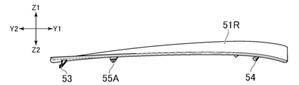
- FIG. 4 is a right side view of the left partial panel of the upper exterior panel.
- FIG. 4 is a plan view of the left partial panel of the upper exterior panel.
- FIG. 4 is a left side view of the left partial panel of the upper exterior panel.
- FIG. 4 is a rear view of the left partial panel of the upper exterior panel.
- FIG. 13 is a bottom view of the left partial panel of the upper exterior panel.
- FIG. 1B is a cross-sectional view taken along line VV shown in FIG.
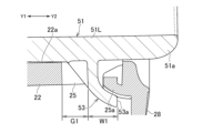
- FIG. 2C is an enlarged view of region VIa shown in FIG. 2B.
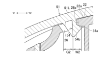
- FIG. 2C is an enlarged view of region VIb shown in FIG. 2B.
- FIG. 6 is an enlarged view of region VIIa shown in FIG. 5 .
- FIG. 6 is an enlarged view of region VIIb shown in FIG. 5 .
- 1B is a cross-sectional view taken along line VIII-VIII shown in FIG. FIG.
- FIG. 9 is an enlarged view of region IXa shown in FIG. 8.
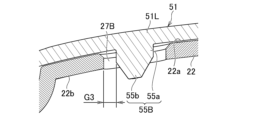
- FIG. 9 is an enlarged view of region IXa shown in FIG. 8.
- 1B is a cross-sectional view taken along line XX shown in FIG. 10A to 10C are cross-sectional views for explaining the process of attaching the exterior panel.
- FIG. 4 is a perspective view showing an inner surface of an upper housing.
- FIG. 4 is a plan view of the right partial panel of the upper exterior panel.
- FIG. 4 is a front view of the right partial panel of the upper exterior panel.
- FIG. 4 is a right side view of the right partial panel of the upper exterior panel.
- FIG. 4 is a left side view of the right partial panel of the upper exterior panel.
- FIG. 4 is a rear view of the right partial panel of the upper exterior panel.
- FIG. 4 is a perspective view showing an inner surface of an upper housing.
- FIG. 4 is a plan view of the right partial panel of the upper exterior panel.
- FIG. 4 is
- FIG. 13 is a bottom view of the right partial panel of the upper exterior panel.
- FIG. 4 is a plan view of the left partial panel of the lower exterior panel.
- FIG. 4 is a front view of the left partial panel of the lower exterior panel.
- FIG. 4 is a right side view of the left partial panel of the lower exterior panel.
- FIG. 4 is a left side view of the left partial panel of the lower exterior panel.
- FIG. 4 is a rear view of the left partial panel of the lower exterior panel.
- FIG. 13 is a bottom view of the left partial panel of the lower exterior panel.
- FIG. 4 is a plan view of the right partial panel of the lower exterior panel.
- FIG. 4 is a front view of the right partial panel of the lower exterior panel.
- FIG. 4 is a right side view of the right partial panel of the lower exterior panel.
- FIG. 4 is a left side view of the right partial panel of the lower exterior panel.
- FIG. 4 is a rear view of the right partial panel of the lower exterior panel.
- FIG. 13 is a bottom view of the right partial panel of the lower exterior panel.
- FIG. 11 is a perspective view showing another example of an electronic device proposed in the present disclosure.
- FIG. 16B is a perspective view showing the underside of the electronic device shown in FIG. 16A.
- FIG. 16B is a plan view of the electronic device shown in FIG. 16A.
- FIG. 16B is a front view of the electronic device shown in FIG. 16A.
- FIG. 16B is a right side view of the electronic device shown in FIG. 16A.
- FIG. 16B is a left side view of the electronic device shown in FIG. 16A.
- FIG. 16B is a perspective view showing the underside of the electronic device shown in FIG. 16A.
- FIG. 16B is a plan view of the electronic device shown in FIG. 16A.
- FIG. 16B is a rear view of the electronic device shown in FIG. 16A.
- FIG. 16B is a bottom view of the electronic device shown in FIG. 16A.
- 16B is a plan view of a left partial panel constituting the lower exterior panel of the electronic device shown in FIG. 16A.
- FIG. 17B is a front view of the left partial panel shown in FIG. 17A.
- FIG. 17B is a right side view of the left partial panel shown in FIG. 17A.
- FIG. 17B is a left side view of the left partial panel shown in FIG. 17A.
- FIG. 17B is a rear view of the left partial panel shown in FIG. 17A.
- FIG. 17B is a bottom view of the left partial panel shown in FIG. 17A.
- the Z1 and Z2 directions shown in FIG. 1A etc. are referred to as the upper and lower directions, respectively.
- the X1 and X2 directions in the same figure are referred to as the right and left directions, respectively
- the Y1 and Y2 directions are referred to as the front and rear directions, respectively.
- These directions are defined to explain the shapes of the elements (components, members, and parts) of electronic device 10 and their relative positional relationships. Therefore, the directions shown in the figures do not limit the attitude of electronic device 10 when in use.
- the electronic device 10 is, for example, an entertainment device that functions as a game device or audio-visual device.
- the electronic device 10 outputs moving image data generated by executing a game program, video and audio data acquired through a network, and video and audio data acquired from a recording medium such as an optical disk to a display device such as a television.
- the electronic device may be a personal computer or a server computer.
- the electronic device 10 has a device body 20, an upper exterior panel 51 that covers the upper surface 22a of the device body 20, and a lower exterior panel 52 that covers the lower surface 23a of the device body 20 (see FIG. 2B).
- the exterior panels 51 and 52 may be curved overall.
- the upper exterior panel 51 may be curved so as to be concave downward in a cut surface along one of the two diagonals, and curved so as to bulge upward in a cut surface along the other diagonal.
- the shape of the lower exterior panel 52 may be symmetrical to that of the upper exterior panel 51 across a horizontal plane (a plane along the circuit board 31 described below).
- the curved form of the exterior panels 51 and 52 is not limited to the example described here. Unlike the example described here, the exterior panels 51 and 52 may be panels parallel to a horizontal plane.
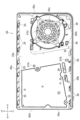
- the device body 20 has a housing 21.
- the housing 21 houses, for example, a circuit board 31.
- the circuit board 31 may be arranged parallel to the front-rear direction (Y1-Y2 direction) and the left-right direction (X1-X2 direction).
- Various electronic components such as a CPU (Central Processing Unit), a GPU (Graphical Processing Unit), and memory are mounted on the circuit board 31.
- the housing 21 may also have a power supply device 34.
- the power supply device 34 receives power from outside the electronic device 10 and supplies the drive power to a device (for example, the circuit board 31) built into the device body 20.
- the power supply device 34 has a case 34a and a circuit board 34b arranged within the case 34a.
- the housing 21 may have, for example, an upper housing 21U and a lower housing 21L that are combined in the vertical direction.
- the upper housing 21U covers the upper side of the various devices (e.g., circuit board 31) built into the device body 20.
- the upper housing 21U has an upper wall 22 that forms the upper surface 22a of the device body 20.
- the upper surface of the case 34a of the power supply device 34 may be exposed upward from an opening formed in the upper wall 22.
- the lower housing 21L covers the lower side of the various devices (e.g., circuit board 31) built into the device body 20.
- the lower housing 21L has a lower wall 23 that forms the lower surface 23a of the device body 20.
- the housing 21 has air intakes 22e and 23e.
- the air intakes 22e and 23e are formed on the upper surface 22a and the lower surface 23a of the device body 20, respectively. That is, the air intakes 22e and 23e are formed on the upper wall 22 and the lower wall 23, respectively.
- Covers 47U and 47L that cover the air intakes 22e and 23e and have multiple openings formed therein may be attached to the edges of the air intakes 22e and 23e.
- the housing 21 contains a cooling fan (not shown) that introduces external air into the housing 21 through the air intakes 22e and 23e.
- the cooling fan is disposed, for example, between the upper and lower air intakes 22e and 23e, and is disposed so that it can rotate around an axis along the vertical direction.
- the housing 21 also contains a heat sink (such as a heat pipe).
- the heat sink is thermally connected to electronic components mounted on the circuit board 31, such as the CPU.
- the cooling fan creates an air flow inside the housing 21 that passes through the heat sink.
- the upper exterior panel 51 may have partial panels 51R and 51L aligned in the left-right direction.
- the right partial panel 51R covers the right part of the upper surface 22a of the device body 20, and the left partial panel 51L covers the left part of the upper surface 22a of the device body 20.
- the lower exterior panel 52 may also have partial panels 52R and 52L aligned in the left-right direction.
- the right partial panel 52R covers the right part of the lower surface 23a of the device body 20, and the left partial panel 52L covers the left part of the lower surface 23a of the device body 20.
- the exterior panels 51 and 52 may cover the air intakes 22e and 23e formed on the upper surface 22a (see FIG. 2A) and the lower surface 23a (see FIG. 2B) of the device body 20, respectively.
- a gap that functions as an air flow path may be formed between the upper exterior panel 51 and the upper surface 22a of the device body 20.
- a gap that functions as an air flow path may be formed between the lower exterior panel 52 and the lower surface 23a of the device body 20.
- the right partial panels 51R and 52R of the upper and lower exterior panels 51 and 52 cover the air intakes 22e and 23e, respectively.
- a gap that functions as an air flow path is formed between the upper right partial panel 51R and the upper surface 22a.
- a gap that functions as an air flow path is formed between the lower right partial panel 52R and the lower surface 23a.
- air intakes Sa and Sb are formed between the outer peripheral edges of the exterior panels 51 and 52 and the outer peripheral edge of the device body 20. More specifically, air intakes Sa and Sb are formed between the front and right edges of the upper right partial panel 51R and the edge of the top surface 22a of the device body 20. Similarly, air intakes Sc and Sd are formed between the front and right edges of the lower right partial panel 52R and the edge of the bottom surface 23a of the device body 20.
- external air is introduced into the air flow path between the upper exterior panel 51 and the upper surface 22a of the device body 20 through the air intakes Sa and Sb formed on the upper side of the device body 20. The air then flows toward the air intake 22e formed on the upper surface 22a of the device body 20.
- External air is also introduced into the air flow path between the lower exterior panel 52 and the lower surface 23a of the device body 20 through the air intakes Sc and Sd formed on the lower side of the device body 20. The air then flows toward the air intake 23e formed on the lower surface 23a of the device body 20.
- the structure of the exterior member of the electronic device 10 is not limited to the example shown in the figure.
- the electronic device 10 may have air intakes formed on the front surface 20b or the left and right side surfaces 20d and 20c of the device body 20, instead of the air intakes Sa to Sd formed between the exterior panels 51 and 52 and the outer periphery of the device body 20.
- a power button and a connector may be provided on the front surface 20b.
- an air intake opening toward the upper side of the electronic device 10 may be formed in the upper exterior panel 51 instead of the air intakes Sa and Sb, or in addition to the air intakes Sa and Sb.
- an air intake opening toward the lower side of the electronic device 10 may be formed in the lower exterior panel 52 instead of the air intakes Sc and Sd, or in addition to the air intakes Sc and Sd.
- the electronic device 10 may have only one of the air intakes Sa and Sb located at the top and the air intakes Sc and Sd located at the bottom.
- each exterior panel 51 and 52 has a right partial panel 51R and 52R and a left partial panel 52L and 52L.
- the right partial panel 51R and the left partial panel 51L of the upper exterior panel 51 may not be connected to each other and may be detached from the device body 20 separately. That is, only the right partial panel 51R may be detached from the device body 20, or only the left partial panel 51L may be detached from the device body 20.
- the right partial panel 52R and the left partial panel 52L of the lower exterior panel 52 may not be connected to each other and may be detached from the device body 20 separately.
- a gap may be formed between the left partial panels 51L and 52L and the right partial panels 51R and 52R.
- each of the partial panels 51R, 51L, 52R, and 52L is essentially the same, so below, the mounting structure will be explained mainly with reference to the left partial panel 51L of the upper exterior panel 51.
- each exterior panel 51 and 52 do not have to have the partial panels 51R, 51L, 52R, and 52L.
- each exterior panel 51 and 52 may be composed of a single panel.
- the structure of the partial panel 51L described below may be applied to the entire upper exterior panel 51.
- the same structure may also be applied to the entire lower exterior panel 52.
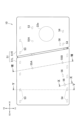
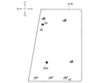
- the partial panel 51L has a rear edge 51a and a front edge 51b.
- the rear edge 51a and the front edge 51b are located on opposite sides to each other in the front-rear direction.
- the rear edge 51a may protrude forward beyond the position of the front surface 20b of the device body 20 (see FIG. 1D).
- the rear edge 51a may protrude backward beyond the position of the rear surface 20a of the device body 20. (See Figure 1D).
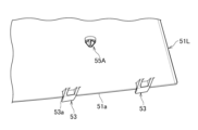
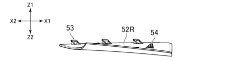
- the partial panel 51L has a rear engagement portion 53 and a front engagement portion 54.
- the rear engagement portion 53 is located rearward of the center of the partial panel 51L in the front-to-rear direction
- the front engagement portion 54 is located forward of the center of the partial panel 51L in the front-to-rear direction.
- the rear engagement portion 53 may be formed along the rear edge 51a
- the front engagement portion 54 may be formed along the front edge 51b.
- the partial panel 51L does not have any other engagement portion between the rear engagement portion 53 and the front engagement portion 54 that engages with the upper surface 22a of the device body 20.
- the partial panel 51L has multiple rear engagement portions 53, which may be aligned in the left-right direction. Also, the partial panel 51L has multiple front engagement portions 54, which may be aligned in the left-right direction.
- the rear engagement portion 53 may be a convex portion that protrudes from the underside of the partial panel 51L toward the device body 20.
- the front engagement portion 54 may be, for example, a convex portion that protrudes from the underside of the partial panel 51L toward the device body 20.
- the front engagement portion 54 protrudes from the underside of the partial panel 51L in a direction that is substantially perpendicular to a horizontal plane along the front-rear and left-right directions.
- a rear engaged portion 25a for engaging with the rear engaging portion 53 is formed on the top surface 22a (upper wall 22) of the device body 20.
- the rear engaging portion 53 engages with the rear engaged portion 25a means that the two mesh together such that the engaged portion 25a restricts the rear engaging portion 53 from separating upward.
- a hole 25 into which the rear engagement portion 53 of the partial panel 51L fits is formed in the top surface 22a (upper wall 22) of the device body 20.
- a rear engaged portion 25a is formed on the edge of the hole 25.
- the rear engaged portion 25a is a portion that contacts the rear engagement portion 53 at the inner edge of the hole 25, rather than the entire inner edge of the hole 25, and that prevents the rear engagement portion 53 from separating upward.
- a front engaged portion 26a for engaging with the front engaging portion 54 is formed on the top surface 22a (upper wall 22) of the device body 20.
- the front engaging portion 54 engages with the front engaged portion 26a means that the two mesh together such that the front engaged portion 26a restricts the front engaging portion 54 from separating upward.
- a hole 26 is formed in the top surface 22a of the device body 20, into which the front engagement portion 54 of the partial panel 51L fits.
- a front engaged portion 26a with which the front engagement portion 54 engages is formed on the edge of the hole 26.
- the front engaged portion 26a is not the entire inner edge of the hole 26, but is a portion that contacts the front engagement portion 54 at the inner edge of the hole 26 and restricts the front engagement portion 54 from separating upward.
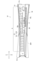
- the partial panel 51L can rotate about the rear engaging portion 53 in a direction in which its front edge 51b approaches the device body 20 (the direction of arrow U1 in FIG. 11) and in a direction in which it moves away from the device body 20 (the direction of arrow U2 in FIG. 11).
- the upper surface 22a of the device body 20 may have a lower portion 22f in which an air intake 22e is formed and which is covered by the right partial panel 51R.
- the lower portion 22f is lower than the portion of the upper surface 22a covered by the left partial panel 51L.
- a hole 26 is also formed in this lower portion 22f.
- a cylindrical portion 26A protruding upward is formed in the lower portion 22f, and its inside functions as the hole 26.
- An engaged portion 26a (see FIG. 7B) may be formed on the inside of this cylindrical portion 26A.
- This cylindrical portion 26A ensures an air flow path between the right partial panel 51R and the upper surface 22a.
- the same structure may also be formed on the lower surface 23a of the device body 20. That is, as shown in FIG. 2B, a bottom portion 23f may be formed on the lower surface 23a, and a cylindrical portion 26A may be formed on this bottom portion.
- This positional relationship between the engaging portions 53, 54 and the engaged portions 25a, 26a allows both the engagement between the front engaging portion 54 and the front engaged portion 26a and the engagement between the rear engaging portion 53 and the rear engaged portion 25a to be easily released, facilitating the removal of the partial panel 51L.
- the engagement between the rear engaging portion 53 and the rear engaged portion 25a can also be naturally released.
- the partial panel 51L may be formed, for example, from a resin so that such bending (curving) of the front portion of the partial panel 51L is possible.
- the material of the partial panel 51L may also be a metal.
- the partial panel 51L does not have side walls at the left edge 51c and the right edge 51e. That is, the partial panel 51L does not have walls at its left edge 51c and right edge 51e that slope down toward the device body 20.
- the partial panel 51L has an end face facing left at its left edge 51c, and an end face facing right at its right edge 51e. Therefore, the above-mentioned curvature of the front part of the partial panel 51L can be performed relatively easily.
- the right partial panel 51R like the left partial panel 51L, does not have side walls that slope down toward the right edge 51d and left edge. That is, the upper exterior panel 51, which is composed of the two partial panels 51R and 51L, does not have side walls that slope down toward the device body 20.
- the distance L2 from the front edge 51b of the partial panel 51L to the front engagement portion 54 is greater than the distance L1 from the rear edge 51a of the partial panel 51L to the rear engagement portion 53.
- the worker bends the front portion of the partial panel 51L upward to release the engagement between the front engagement portion 54 and the front engaged portion 26a.
- the distance L1 is relatively large, it is possible to bend the front portion of the partial panel 51L with a small force. As a result, the operation of removing the partial panel 51L can be further facilitated.
- the front engagement portion 54 may be located forward of the middle position of the partial panel 51L in the front-to-rear direction.
- the rear engaged portion 25a may be formed, for example, at the rear end of the upper wall 22.
- the rear engaged portion 25a may be formed, for example, at the upper end of the rear wall 28 (see FIG. 7A) of the housing 21.
- Forming the rear engaged portion 25a in this manner facilitates alignment of the rear engaging portion 53 with the rear engaged portion 25a, in other words, alignment of the rear engaging portion 53 with the hole 25.
- the rear engaging portion 53 can be smoothly engaged with the rear engaged portion 25a.
- the front engaging portion 54 is located toward the front, the worker can easily visually confirm the position of the hole 26 in the process of attaching the partial panel 51L to the housing 21. As a result, the worker can smoothly perform the work of attaching the partial panel 51L to the device main body 20.
- the front engaged portion 26a may be formed at a position rearwardly spaced from the front end of the upper surface 22a of the device body 20 (at a position rearwardly spaced from the front surface 20b (see FIG. 5) of the device body 20).
- the front engaging portion 54 may be formed at a position rearwardly spaced from the front edge 51b of the partial panel 51L.
- the rear engaged portion 25a may be, for example, a protrusion protruding forward from the rear of the inner edge of the hole 25.
- the rear engaging portion 53 has a rear side When the rear engaging portion 53 and the rear engaged portion 25a are engaged with each other, the claw portion 53a extends downward from the rear engaged portion 25a, which is a convex portion. is placed to the side.
- At least one of the lower surface of the rear engaged portion 25a (contact surface with the claw portion 53a) and the upper surface of the claw portion 53a (contact surface with the rear engaged portion 25a) may be curved in an arc. This allows the partial panel 51L to be rotated smoothly when removing or attaching the partial panel 51L. In the example shown in FIG. 7A, both the lower surface of the rear engaged portion 25a and the upper surface of the claw portion 53a are curved in an arc.
- the front engaged portion 26a may be the rear of the inner edge of the hole 26.
- the front engaging portion 54 has a claw portion 54a at its lower portion that extends toward the rear. When the front engaging portion 54 and the front engaged portion 26a are engaged, the claw portion 54a is positioned below the rear engaged portion 26a.
- the claw portion 54a may have a slope 54b formed thereon.
- the slope 54b extends obliquely upward and rearward from the lower end of the claw portion 54a.
- the slope 54b interferes with the rear part of the inner edge of the hole 26 (the upper surface of the front engaged portion 26a), causing elastic deformation of the front engaging portion 54.
- the claw portion 54a climbs over the front engaged portion 26a and engages with the front engaged portion 26a.
- the protruding amount of the claw portion 54a of the front engagement portion 54 may be smaller than the protruding amount of the claw portion 53a of the rear engagement portion 53 (width W1 in the front-to-rear direction, see FIG. 7A). This makes it easier to disengage the front engagement portion 54 from the front engaged portion 26a when the front portion of the partial panel 51L is bent upward to remove the partial panel 51L from the device body 20.
- the housing 21 has a rear wall 28.
- the rear wall 28 is formed with an exhaust port D having a plurality of louvers 28a.
- the louvers 28a may be aligned in the left-right direction, for example.
- the louvers 28a may be inclined to one side in the left-right direction.
- An opening (d) is formed between two adjacent louvers 28a.
- the hole 25 in which the rear engagement portion 25a is formed is formed between two adjacent louvers 28a, and is located above one opening (d) defined between the two louvers 28a.
- the holes 25 may be formed at an angle to match the inclination of the louvers 28a.
- the engagement portions 53 formed on the partial panel 51L may also be formed at an angle to match the holes 25, in other words, to match the inclination of the louvers 28a. More specifically, in a plan view of the electronic device 10, the louvers 28a may extend at an angle rearward and to the left.
- the rear engagement portions 53 may also extend in the same direction. This structure of the rear engagement portions 53 makes it easier to ensure the size of the rear engagement portions 53 and the rear engaged portions 25a in the left-right direction.
- the partial panel 51L has a first fitting portion 55A.
- the first fitting portion 55A may be located, for example, forward of the rear engagement portion 53 and rearward of the front engagement portion 54.
- the first fitting portion 55A may be a protrusion that protrudes from the lower surface of the partial panel 51L toward the device body 20.
- the device body 20 has a first mating portion 27A on its top surface 22a into which the first mating portion 55A fits.
- the first mating portion 27A may be, for example, a hole into which the first mating portion 55A fits.
- both of the engaged portions 25a, 26a are located behind the engaging portions 53, 54. Therefore, the engaging portions 53, 54 and the engaged portions 25a, 26a alone allow the partial panel 51L to move forward. To prevent this movement of the partial panel 51L, the first fitting portion 55A and the first fitted portion 27A fit together, restricting the forward movement of the partial panel 51L relative to the device body 20.
- the inner edge of the hole that is the first mating portion 27A may have a size that corresponds to the protrusion that is the first mating portion 55A. This effectively restricts the forward movement of the partial panel 51L, and prevents the engagement between the engagement portions 53 and 54 and the mating portions 25a and 26a from being unintentionally released.
- the partial panel 51L has multiple front engagement portions 54.
- the number of first fitting portions 55A may be less than the number of front engagement portions 54.
- the number of first fitting portions 55A may be less than the number of rear engagement portions 53.
- the number of first fitting portions 55A provided on each partial panel 51L may be one.
- the claw portion 53a of the rear engagement portion 53 has a width W1 (see FIG. 7A) in the front-to-rear direction.
- the claw portion 54a of the front engagement portion 54 has a width W2 (see FIG. 7B) in the front-to-rear direction.
- the clearance between the inner edge of the hole that is the first engaged portion 27A and the outer circumferential surface of the first engaged portion 55A may be smaller than this width W1/W2. This effectively prevents the engagement between the engagement portions 53/54 and the engaged portions 25a/26a from being unintentionally released.
- a clearance G1 is provided between the inner edge of the hole 25 in which the rear engaged portion 25a is formed and the rear engaging portion 53.
- This clearance G1 makes it easy to place the partial panel 51L in an oblique position and fit the rear engaging portion 53 into the hole 25, as shown in FIG. 11.
- the clearance between the inner edge of the hole, which is the first engaged portion 27A (see FIG. 9A), and the outer peripheral surface of the first engaged portion 55A may be smaller than the clearance G1.
- the clearance between the inner edge of the hole, which is the first engaged portion 27A, and the outer peripheral surface of the first engaged portion 55A may be substantially zero, as shown in FIG. 9A. In other words, the outer peripheral surface of the first engaged portion 55A may be in contact with the inner edge of the hole, which is the first engaged portion 27A.
- a clearance G2 is provided between the inner edge of the hole 26 in which the front engaged portion 26a is formed and the front engaging portion 54.
- This clearance G2 allows the front engaging portion 54 to be smoothly fitted into the hole 26 during the process of attaching the partial panel 51L to the device body 20.
- the clearance between the inner edge of the hole, which is the first engaged portion 27A (see FIG. 9A), and the outer peripheral surface of the first engaged portion 55A may be smaller than the clearance G2.
- the clearance between the inner edge of the hole, which is the first engaged portion 27A, and the outer peripheral surface of the first engaged portion 55A may be substantially zero. In other words, the outer peripheral surface of the first engaged portion 55A may be in contact with the inner edge of the hole, which is the first engaged portion 27A.
- the rear engaging portion 53 is formed with a claw portion 53a extending toward the rear.
- the claw portion may be formed on the engaged portion 25a formed on the upper surface 22a of the housing 21.
- the rear engaged portion 25a may be a convex portion that protrudes upward from the upper surface 22a of the housing 21.
- the claw portion may protrude forward from this convex portion (rear engaged portion 25a).
- a recess may be formed in the partial panel 51L, and the edge of this recess may function as the rear engaging portion 53.
- the claw portion formed on the rear engaged portion 25a may engage with this rear engaging portion 53 (edge of the recess).
- the front engaging portion 54 is formed with a claw portion 54a extending toward the rear.
- the claw portion may be formed on the engaged portion 26a formed on the upper surface 22a of the housing 21.
- the rear engaged portion 26a may be a convex portion that protrudes upward from the upper surface 22a of the housing 21.
- the claw portion may protrude forward from this convex portion (rear engaged portion 26a).
- a recess may be formed in the partial panel 51L, and the edge of this recess may function as the front engaging portion 54.
- the claw portion formed on the rear engaged portion 26a may engage with this front engaging portion 54 (edge of the recess).
- the clearance between the inner edge of the hole, which is the first engaged portion 27A (see FIG. 9A), and the first engaged portion 55A may be smaller than the width of the claw portion.
- the partial panel 51L has a second fitting portion 55B.
- the second fitting portion 55B may be located, for example, forward of the rear engagement portion 53 and rearward of the front engagement portion 54.
- the second fitting portion 55B may be located forward of the first fitting portion 55A.
- the second fitting portion 55B may be, for example, a convex portion that protrudes from the underside of the partial panel 51L toward the device body 20.
- the device body 20 has a second mating portion 27B on its upper surface 22a into which the second mating portion 55B fits.
- the second mating portion 27B may be, for example, a hole into which the second mating portion 55B fits.
- the size in the left-right direction of the inner edge of the hole that is the second mating portion 27B may correspond to the size in the left-right direction of the protrusion that is the second mating portion 55B.
- the second mating portion 55B may have a gap G3 in the front-rear direction between it and the second mating portion 27B.
- the engaging portions 55A and 55B and the engaged portions 27A and 27B restrict the movement of the partial panel 51L relative to the device body 20. More specifically, the translation in the front-rear and left-right directions and the rotation of the partial panel 51L in the horizontal plane are restricted.
- the mating portions 55A and 55B do not have claws.
- the mating portions 55A and 55B may have, for example, a columnar base 55a and a guided portion 55b that extends downward from the base 55a and tapers gradually toward the tip (the diameter gradually decreases toward the tip).
- the contact surfaces of the mating portions 55A and 55B and the mated portions 27A and 27B may be substantially perpendicular to the horizontal direction.
- the outer peripheral surface of the base 55a of the first mating portion 55A and the inner surface of the hole that is the first mated portion 27A may be substantially perpendicular to the front-rear and left-right directions. This effectively suppresses movement of the partial panel 51L relative to the device main body 20 (movement in the front-rear and left-right directions).
- the outer peripheral surface of the base 55a of the second fitting portion 55B and the inner surface of the hole that is the second fitted portion 27B may be substantially perpendicular to the left-right direction. This effectively prevents the movement (rotation in the horizontal plane) of the partial panel 51L relative to the device main body 20.
- the rear engagement portion 53 is engaged with the rear engaged portion 25a.
- the front edge 51b of the partial panel 51L is brought closer toward the device body 20.
- the claw portion 54a of the front engagement portion 54 of the partial panel 51L interferes with the edge of the hole 26 of the device body 20 (the engaged portion 26a in the example shown in the figure).
- the first fitting portion 55A at least partially fits into the first engaged portion 27A. This limits the forward movement of the partial panel 51L.
- the front engagement portion 54 elastically deforms, and the claw portion 54a engages with the front engaged portion 26a.
- the second fitting portion 55B may also at least partially fit into the second engaged portion 27B.
- a guide surface 54c may be formed on the right side of the front engagement part 54, as shown in FIG. 6B.
- the guide surface 54c may be an inclined surface that is inclined in the left-right direction.
- the guide surface 54c may be formed on the left side of the front engagement portion 54.
- the guide surface 54c guides the inner edge of the hole 26, and the engagement between the front engagement portion 54 and the front engaged portion 26a is released.
- the right partial panel 51R separates from the device main body 20. This prevents excessive load from acting on the engagement portions 53 and 54.
- the slope that facilitates separation of the partial panel 51L from the device body 20 may be formed on the rear engagement portion 53, not on the front engagement portion 54. Also, this slope may be formed on the inner edges of the holes 25 and 26, not on the engagement portions 53 and 54.
- the front edge 51b of the left partial panel 51L protrudes forward beyond the front surface 20b of the device body 20. Therefore, when the electronic device 10 is dropped with its front side facing down and the front edge 51b hits the floor, the relative positions of the device body 20 and the left partial panel 51L are shifted, and a large load acts on the engagement portions 53 and 54 of the left partial panel 51L.
- the partial panel 51L may have an auxiliary engagement portion 56, as shown in Figures 6B and 10.
- the auxiliary engagement portion 56 may be formed, for example, along the front edge 51b of the partial panel 51L together with the front engagement portion 54.
- a fitted portion 29 (see Figure 10) into which the auxiliary engagement portion 56 fits may be formed on the upper surface 22a of the device body 20.
- the auxiliary engagement portion 56 may be, for example, a convex portion that protrudes from the lower surface of the partial panel 51L toward the device body 20.
- the fitted portion 29 may be a hole into which this convex portion fits.
- the auxiliary fitting portion 56 has a support surface 56a facing rearward. Meanwhile, the inner surface of the hole which is the fitted portion 29 has a supported surface 29c which faces the support surface 56a in the front-to-rear direction.
- the rear edge 51a of the left partial panel 51L protrudes rearward beyond the rear surface 20a of the device body 20. Therefore, when the electronic device 10 is dropped with its rear side facing down, the rear edge 51a hits the floor. Since both of the engaged portions 25a and 26a are located behind the engaging portions 53 and 54, when the rear edge 51a hits the floor, the engagement between the engaging portions 53 and 54 and the engaged portions 25a and 26a is released, and the partial panel 51L can be smoothly separated from the device body 20.
- the auxiliary fitting portion 56 may have a guide surface 56b on the opposite side to the support surface 56a.
- the guide surface 56b is a slope, and when the electronic device 10 is dropped with its rear side facing down, the auxiliary fitting portion 56 smoothly comes out of the hole that is the fitting portion 29 due to the action of the guide surface 56b.
- the mating portions 55A and 55B do not have claws. Therefore, when the electronic device 10 is dropped and the edge of the partial panel 51L hits the floor, the mating portions 55A and 55B smoothly come out of the mated portions 27A and 27B, preventing excessive load from being applied to the mating portions 55A and 55B.
- the mating portions 55A and 55B have a base 55a (see Figures 9A and 9B) with an outer peripheral surface along the up-down direction.
- the base 55a prevents the partial panel 51L from moving in the front-back and left-right directions relative to the device body 20.
- the height of the base 55a is low. Specifically, the height of the base 55a does not exceed the lower surface 22b of the upper wall 22. Therefore, when the electronic device 10 falls and the edge of the partial panel 51L hits the floor, the mating portions 55A and 55B smoothly come out of the mated portions 27A and 27B.
- 13A to 13F are views showing the right partial panel 51R of the upper exterior panel 51.
- the right partial panel 51R has engagement portions 53 and 54, a first fitting portion 55A, and an auxiliary fitting portion 56.
- FIGS. 14A to 14F show the left partial panel 52L of the lower exterior panel 52.
- the left partial panel 52L has engagement portions 53 and 54, a first fitting portion 55A, a second fitting portion 55B, and an auxiliary fitting portion 56.
- FIGS. 15A to 15F show the right partial panel 52R of the lower exterior panel 52.
- the right partial panel 52R has engagement portions 53 and 54, a first fitting portion 55A, and an auxiliary fitting portion 56.
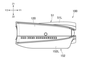
- FIGS. 16A to 16H are diagrams showing electronic device 110, which is a modified example of the electronic device presented in this disclosure.
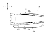
- Electronic device 110 has a device body 120 and an upper exterior panel 51 having the left partial panel 51L and right partial panel 51R described above.
- Electronic device 110 has a lower exterior panel 152.
- Lower exterior panel 152 has a left partial panel 152L and a right partial panel 52R.
- Device body 120 has an optical disc drive.
- Left partial panel 152L has an optical disc insertion slot 152a (see FIG. 6B) on its front surface.
- FIGS. 17A to 17F show the left partial panel 152L shown in FIG. 16A etc.
- the left partial panel 152L has engagement portions 53 and 54, a first fitting portion 55A, a second fitting portion 55B, and an auxiliary fitting portion 56, similar to the lower left panel 52L.
- the electronic device proposed in this disclosure has a device main body having a first outer surface and an exterior panel covering the first outer surface.
- the exterior panel has a first engaging portion located on a first side with respect to the center of the exterior panel in a first direction, a second engaging portion located on a second side opposite the first side with respect to the center of the exterior panel in the first direction, and a fitting portion.
- the device main body has a first engaged portion with which the first engaging portion engages, a second engaged portion with which the second engaging portion engages, and a fitted portion with which the fitting portion fits.
- the first engaged portion is located on the first side with respect to the first engaging portion in the first direction
- the second engaged portion is located on the first side with respect to the second engaging portion in the first direction.
- the fitted portion fits into the fitting portion and restricts the movement of the exterior panel to the second side in the first direction.
- the engagement between the first engaging part and the first engaged part and the engagement between the second engaging part and the second engaged part can both be easily released, facilitating the removal of the exterior panel.
- the action of the fitting part can prevent the exterior panel from being unintentionally separated from the device body.
- the first engaging portion and the second engaging portion may be convex portions that protrude toward the device body.
- the device body may have a first hole into which the first engaging portion fits, and a second hole into which the second engaging portion fits.
- the first engaged portion may be provided on the edge of the first hole, and the second engaged portion may be provided on the edge of the second hole.
- the exterior panel has a first edge and a second edge located opposite each other in the first direction.
- the first exterior panel can rotate about the first engaging portion in a direction in which the second edge moves away from the device body and in a direction in which the second edge moves toward the device body. This allows the exterior panel to be attached to and detached from the device body with a simple operation.
- the exterior panel can be attached to the device body by engaging the first engaging portion with the first engaged portion and rotating the exterior panel so that the second edge moves toward the device body.
- the engagement between the second engaging portion and the second engaged portion can be released by bending the portion of the exterior panel where the second engaging portion is formed. Then, by rotating the exterior panel so that the second edge moves away from the device body, the engagement between the first engaging portion and the first engaged portion can be released, and the exterior panel can be removed from the device body.
- the distance from the second edge to the second engaging portion may be greater than the distance from the first edge to the first engaging portion. This makes it easier to disengage the second engaging portion from the second engaged portion by bending the portion of the exterior panel where the second engaging portion is formed.
- one of the first engaging portion and the first engaged portion may have a first claw portion protruding from the one of them.
- One of the second engaging portion and the second engaged portion may have a second claw portion protruding from the one of them.
- One of the fitting portion and the engaged portion may be a convex portion, and the other may be a hole into which the convex portion fits. The clearance between the convex portion and the inner surface of the hole is smaller than the amount of protrusion of the first claw portion and the amount of protrusion of the second claw portion. In this way, the fitting portion and the engaged portion can prevent movement of the exterior panel that would release the engagement between the first and second claw portions.
- the first engaging portion may be a protrusion that protrudes toward the device body.
- the device body may have a first hole into which the first engaging portion fits.
- the first engaged portion may be provided on the edge of the first hole.
- the engaged portion may be a third hole formed in the device body. The clearance between the edge of the third hole and the engaging portion may be smaller than the clearance between the edge of the first hole and the first engaging portion.
- the second engaging portion may be a protrusion that protrudes toward the device body.
- the device body may have a second hole into which the second engaging portion fits.
- the second engaged portion may be provided on the edge of the second hole.
- the engaged portion may be a third hole formed in the device body. The clearance between the edge of the third hole and the engaging portion may be smaller than the clearance between the edge of the second hole and the second engaging portion.
- one of the engaging portion and the engaged portion may be a protruding portion that engages with the other.
- the protruding portion may not be formed with a claw portion that engages with the other.
- the electronic device proposed in this disclosure has a device body having a first outer surface and an exterior panel covering the first outer surface.
- the exterior panel has a first edge and a second edge located opposite each other in a first direction, a first engaging portion formed closer to the first edge than the center of the exterior panel in the first direction, and a second engaging portion formed closer to the second edge than the center of the exterior panel.
- the first exterior panel can rotate about the first engaging portion in a direction in which the second edge moves away from the device body and in a direction in which the second edge moves toward the device body.
- the distance from the second edge to the second engaging portion is greater than the distance from the first edge to the first engaging portion.
- the exterior panel can be attached and detached to the device body with a simple operation.
- the exterior panel can be attached to the device body by engaging the first engaging portion with the first engaged portion and rotating the exterior panel so that the second edge approaches the device body.
- the engagement between the second engaging portion and the second engaged portion can be released by bending the portion of the exterior panel where the second engaging portion is formed.
- the exterior panel proposed in this disclosure has a first edge and a second edge located opposite each other in a first direction, a first engaging portion formed on a first side of the center of the exterior panel in the first direction for engaging with a first engaged portion formed on the device body, a second engaging portion formed on a second side of the center of the exterior panel in the first direction for engaging with a second engaged portion formed on the device body, and a fitting portion for fitting into a fitted portion formed on the device body.
- the first engaging portion has a claw portion protruding to the first side in the first direction.
- the second engaging portion has a claw portion protruding to the first side in the first direction.
- the claw portions of both the first and second engaged portions protrude to the first side, so that both the engagement between the first engaging portion and the first engaged portion and the engagement between the second engaging portion and the second engaged portion can be easily released. Additionally, the fitting section helps prevent the exterior panel from unintentionally separating from the device body.
- the fitting portion does not need to be formed with a claw portion for engaging with the fitted portion.
- the exterior panel proposed in this disclosure has a first edge and a second edge located opposite each other in a first direction, a first engaging portion formed closer to the first edge than the center of the exterior panel in the first direction and for engaging with a first engaged portion formed on the device body, and a second engaging portion formed closer to the second edge than the center of the exterior panel in the first direction and for engaging with a second engaged portion formed on the device body.
- the distance from the second edge to the second engaging portion is greater than the distance from the first edge to the second engaging portion.
- the above-mentioned attachment structure including the engagement portions 53 and 54 may be applied to only one of the upper exterior panel 51 and the lower exterior panel 52. In this case, the electronic device 10 does not need to have the other exterior panel.
- engaging portions 53 and 54 are convex portions, and engaged portions 25a and 26a are formed on the inner edges of holes formed in device body 20.
- convex portions may be formed on the device body as engaged portions, holes may be formed in exterior panels 51 and 52, and engaging portions 53 and 54 may be formed on the inside of the holes.
- mating portions 55A and 55B are convex portions, and mated portions 27A and 27B are holes formed in device body 20.
- convex portions may be formed as mated portions in device body 20, and holes may be formed in exterior panels 51 and 52, with the holes functioning as mating portions.
- the upper exterior panel 51 may be capable of rotating its rear edge 51a in a direction approaching the device body 20 and in a direction away from the device body 20 with its front engagement portion 54 engaged with the engaged portion 26a of the device body 20.
- both of the engaged portions 25a and 26a may be located in front of the engagement portions 53 and 54. In this way, the user can disengage the rear engagement portion 53 from the rear engaged portion 25a by bending the rear portion of the exterior panel 51 upward.
Landscapes
- Engineering & Computer Science (AREA)
- Theoretical Computer Science (AREA)
- General Engineering & Computer Science (AREA)
- Human Computer Interaction (AREA)
- Physics & Mathematics (AREA)
- General Physics & Mathematics (AREA)
- Computer Hardware Design (AREA)
- Power Engineering (AREA)
- Microelectronics & Electronic Packaging (AREA)
- Casings For Electric Apparatus (AREA)
Priority Applications (4)
| Application Number | Priority Date | Filing Date | Title |
|---|---|---|---|
| CN202480012688.7A CN120712902A (zh) | 2023-02-21 | 2024-02-14 | 电子设备和外部面板 |
| JP2025502304A JPWO2024176921A1 (https=) | 2023-02-21 | 2024-02-14 | |
| KR1020257030875A KR20250151456A (ko) | 2023-02-21 | 2024-02-14 | 전자 디바이스 및 외장 패널 |
| EP24760222.0A EP4672879A1 (en) | 2023-02-21 | 2024-02-14 | ELECTRONIC DEVICE AND OUTDOOR PANEL |
Applications Claiming Priority (2)
| Application Number | Priority Date | Filing Date | Title |
|---|---|---|---|
| JP2023-025544 | 2023-02-21 | ||
| JP2023025544 | 2023-02-21 |
Publications (1)
| Publication Number | Publication Date |
|---|---|
| WO2024176921A1 true WO2024176921A1 (ja) | 2024-08-29 |
Family
ID=92501069
Family Applications (1)
| Application Number | Title | Priority Date | Filing Date |
|---|---|---|---|
| PCT/JP2024/005082 Ceased WO2024176921A1 (ja) | 2023-02-21 | 2024-02-14 | 電子機器及び外装パネル |
Country Status (5)
| Country | Link |
|---|---|
| EP (1) | EP4672879A1 (https=) |
| JP (1) | JPWO2024176921A1 (https=) |
| KR (1) | KR20250151456A (https=) |
| CN (1) | CN120712902A (https=) |
| WO (1) | WO2024176921A1 (https=) |
Citations (4)
| Publication number | Priority date | Publication date | Assignee | Title |
|---|---|---|---|---|
| JP2004139558A (ja) * | 2002-09-27 | 2004-05-13 | Casio Comput Co Ltd | 電子機器およびそのカバー部材 |
| JP5657158B1 (ja) * | 2014-05-13 | 2015-01-21 | 任天堂株式会社 | カバーおよびカバー付情報処理装置 |
| WO2021193881A1 (ja) | 2020-03-27 | 2021-09-30 | 株式会社ソニー・インタラクティブエンタテインメント | 電子機器及びその外装パネル |
| JP2021158287A (ja) * | 2020-03-27 | 2021-10-07 | 株式会社ソニー・インタラクティブエンタテインメント | 電子機器及びその外装パネル |
-
2024
- 2024-02-14 JP JP2025502304A patent/JPWO2024176921A1/ja active Pending
- 2024-02-14 WO PCT/JP2024/005082 patent/WO2024176921A1/ja not_active Ceased
- 2024-02-14 EP EP24760222.0A patent/EP4672879A1/en active Pending
- 2024-02-14 CN CN202480012688.7A patent/CN120712902A/zh active Pending
- 2024-02-14 KR KR1020257030875A patent/KR20250151456A/ko active Pending
Patent Citations (4)
| Publication number | Priority date | Publication date | Assignee | Title |
|---|---|---|---|---|
| JP2004139558A (ja) * | 2002-09-27 | 2004-05-13 | Casio Comput Co Ltd | 電子機器およびそのカバー部材 |
| JP5657158B1 (ja) * | 2014-05-13 | 2015-01-21 | 任天堂株式会社 | カバーおよびカバー付情報処理装置 |
| WO2021193881A1 (ja) | 2020-03-27 | 2021-09-30 | 株式会社ソニー・インタラクティブエンタテインメント | 電子機器及びその外装パネル |
| JP2021158287A (ja) * | 2020-03-27 | 2021-10-07 | 株式会社ソニー・インタラクティブエンタテインメント | 電子機器及びその外装パネル |
Non-Patent Citations (1)
| Title |
|---|
| See also references of EP4672879A1 |
Also Published As
| Publication number | Publication date |
|---|---|
| JPWO2024176921A1 (https=) | 2024-08-29 |
| CN120712902A (zh) | 2025-09-26 |
| KR20250151456A (ko) | 2025-10-21 |
| EP4672879A1 (en) | 2025-12-31 |
Similar Documents
| Publication | Publication Date | Title |
|---|---|---|
| TWI775359B (zh) | 電子裝置及電子裝置之外格板 | |
| JP7609848B2 (ja) | 電子機器及びその外装パネル | |
| JP7275380B2 (ja) | 電子機器 | |
| JP7542608B2 (ja) | 電子機器 | |
| WO2021193622A1 (ja) | 電子機器 | |
| WO2021193879A1 (ja) | 電子機器 | |
| JP5800859B2 (ja) | 電子機器 | |
| WO2024176921A1 (ja) | 電子機器及び外装パネル | |
| JP6502900B2 (ja) | 電子機器 | |
| EP3439444B1 (en) | Electronic device | |
| JP7660558B2 (ja) | 電子機器 | |
| JP7820567B2 (ja) | 光ディスクドライブ、電子機器ユニット | |
| JP7823228B2 (ja) | 接続構造、光ディスクドライブ | |
| EP4672877A1 (en) | ELECTRONIC DEVICE ASSEMBLY, ELECTRONIC DEVICE AND SUPPORT | |
| WO2024176922A1 (ja) | 電子機器 | |
| WO2024176919A1 (ja) | 電子機器 | |
| JP2962328B1 (ja) | パネル取付構造 | |
| JP2002108501A (ja) | パーソナルコンピューターのコンピューター本体 |
Legal Events
| Date | Code | Title | Description |
|---|---|---|---|
| 121 | Ep: the epo has been informed by wipo that ep was designated in this application |
Ref document number: 24760222 Country of ref document: EP Kind code of ref document: A1 |
|
| ENP | Entry into the national phase |
Ref document number: 2025502304 Country of ref document: JP Kind code of ref document: A |
|
| WWE | Wipo information: entry into national phase |
Ref document number: 2025502304 Country of ref document: JP |
|
| WWE | Wipo information: entry into national phase |
Ref document number: 202517079481 Country of ref document: IN |
|
| WWP | Wipo information: published in national office |
Ref document number: 202517079481 Country of ref document: IN |
|
| ENP | Entry into the national phase |
Ref document number: 1020257030875 Country of ref document: KR Free format text: ST27 STATUS EVENT CODE: A-0-1-A10-A15-NAP-PA0105 (AS PROVIDED BY THE NATIONAL OFFICE) |
|
| WWE | Wipo information: entry into national phase |
Ref document number: 2024760222 Country of ref document: EP |
|
| NENP | Non-entry into the national phase |
Ref country code: DE |
|
| WWP | Wipo information: published in national office |
Ref document number: 1020257030875 Country of ref document: KR |
|
| ENP | Entry into the national phase |
Ref document number: 2024760222 Country of ref document: EP Effective date: 20250922 |
|
| ENP | Entry into the national phase |
Ref document number: 2024760222 Country of ref document: EP Effective date: 20250922 |
|
| WWP | Wipo information: published in national office |
Ref document number: 2024760222 Country of ref document: EP |