WO2024176898A1 - プログラム、表示制御装置及び制御方法 - Google Patents
プログラム、表示制御装置及び制御方法 Download PDFInfo
- Publication number
- WO2024176898A1 WO2024176898A1 PCT/JP2024/004880 JP2024004880W WO2024176898A1 WO 2024176898 A1 WO2024176898 A1 WO 2024176898A1 JP 2024004880 W JP2024004880 W JP 2024004880W WO 2024176898 A1 WO2024176898 A1 WO 2024176898A1
- Authority
- WO
- WIPO (PCT)
- Prior art keywords
- image
- display mode
- display
- control unit
- character information
- Prior art date
- Legal status (The legal status is an assumption and is not a legal conclusion. Google has not performed a legal analysis and makes no representation as to the accuracy of the status listed.)
- Ceased
Links
Images





Classifications
-
- G—PHYSICS
- G10—MUSICAL INSTRUMENTS; ACOUSTICS
- G10L—SPEECH ANALYSIS TECHNIQUES OR SPEECH SYNTHESIS; SPEECH RECOGNITION; SPEECH OR VOICE PROCESSING TECHNIQUES; SPEECH OR AUDIO CODING OR DECODING
- G10L15/00—Speech recognition
- G10L15/26—Speech to text systems
-
- G—PHYSICS
- G06—COMPUTING OR CALCULATING; COUNTING
- G06F—ELECTRIC DIGITAL DATA PROCESSING
- G06F3/00—Input arrangements for transferring data to be processed into a form capable of being handled by the computer; Output arrangements for transferring data from processing unit to output unit, e.g. interface arrangements
- G06F3/16—Sound input; Sound output
- G06F3/167—Audio in a user interface, e.g. using voice commands for navigating, audio feedback
-
- G—PHYSICS
- G10—MUSICAL INSTRUMENTS; ACOUSTICS
- G10L—SPEECH ANALYSIS TECHNIQUES OR SPEECH SYNTHESIS; SPEECH RECOGNITION; SPEECH OR VOICE PROCESSING TECHNIQUES; SPEECH OR AUDIO CODING OR DECODING
- G10L15/00—Speech recognition
- G10L15/22—Procedures used during a speech recognition process, e.g. man-machine dialogue
-
- H—ELECTRICITY
- H04—ELECTRIC COMMUNICATION TECHNIQUE
- H04N—PICTORIAL COMMUNICATION, e.g. TELEVISION
- H04N9/00—Details of colour television systems
- H04N9/12—Picture reproducers
- H04N9/31—Projection devices for colour picture display, e.g. using electronic spatial light modulators [ESLM]
- H04N9/3141—Constructional details thereof
-
- H—ELECTRICITY
- H04—ELECTRIC COMMUNICATION TECHNIQUE
- H04N—PICTORIAL COMMUNICATION, e.g. TELEVISION
- H04N9/00—Details of colour television systems
- H04N9/12—Picture reproducers
- H04N9/31—Projection devices for colour picture display, e.g. using electronic spatial light modulators [ESLM]
- H04N9/3179—Video signal processing therefor
-
- H—ELECTRICITY
- H04—ELECTRIC COMMUNICATION TECHNIQUE
- H04N—PICTORIAL COMMUNICATION, e.g. TELEVISION
- H04N9/00—Details of colour television systems
- H04N9/12—Picture reproducers
- H04N9/31—Projection devices for colour picture display, e.g. using electronic spatial light modulators [ESLM]
- H04N9/3191—Testing thereof
- H04N9/3194—Testing thereof including sensor feedback
-
- G—PHYSICS
- G06—COMPUTING OR CALCULATING; COUNTING
- G06F—ELECTRIC DIGITAL DATA PROCESSING
- G06F3/00—Input arrangements for transferring data to be processed into a form capable of being handled by the computer; Output arrangements for transferring data from processing unit to output unit, e.g. interface arrangements
- G06F3/14—Digital output to display device ; Cooperation and interconnection of the display device with other functional units
-
- G—PHYSICS
- G09—EDUCATION; CRYPTOGRAPHY; DISPLAY; ADVERTISING; SEALS
- G09G—ARRANGEMENTS OR CIRCUITS FOR CONTROL OF INDICATING DEVICES USING STATIC MEANS TO PRESENT VARIABLE INFORMATION
- G09G2340/00—Aspects of display data processing
- G09G2340/04—Changes in size, position or resolution of an image
- G09G2340/0492—Change of orientation of the displayed image, e.g. upside-down, mirrored
Definitions
- This disclosure relates to a program, a display control device, and a control method.
- Patent Document 1 Technologies for displaying images on a display unit are known (for example, see Patent Document 1).
- the display device described in Patent Document 1 displays multiple images in their respective display areas, detects user operations on the image display areas, and changes the image display areas and display states in response to the detected user operations.
- a program includes: A display control device includes: Obtaining text information converted by speech recognition; operating in a first display mode in which an image corresponding to a keyword included in the character information is displayed on a display unit located between a first user and a second user; transitioning from the first display mode to a second display mode when a first condition is satisfied while in the first display mode; In the second display mode, the image is displayed on the display unit in a display manner different from that in the first display mode.
- a display control device includes: a control unit that operates in a first display mode in which character information converted by voice recognition is acquired and an image corresponding to a keyword included in the character information is displayed on a display unit located between a first user and a second user, and that transitions from the first display mode to a second display mode when a first condition is satisfied while in the first display mode;
- the control unit is In the second display mode, the image is displayed on the display unit in a display manner different from that in the first display mode.
- a control method includes: Obtaining text information converted by speech recognition; operating in a first display mode in which an image corresponding to a keyword included in the character information is displayed on a display unit located between a first user and a second user; transitioning from the first display mode to a second display mode when a first condition is satisfied while in the first display mode; In the second display mode, the image is displayed on the display unit in a display manner different from that in the first display mode.
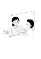
- FIG. 1 is a diagram illustrating a schematic configuration of a display system according to an embodiment of the present disclosure.
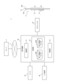
- FIG. 2 is a block diagram of the display system shown in FIG. 1 .
- FIG. 2 is a diagram showing a configuration of a first display area and a second display area as viewed from a first user.
- FIG. 13 is a diagram showing a configuration of the first display area and the second display area as viewed from a second user.
- FIG. 13 is a diagram showing a first display area initialized in a second display mode.
- FIG. 13 is a diagram showing a display example of the first display area in the second display mode.
- FIG. 13 is a diagram showing a display example of the first display area in the second display mode.
- 13A to 13C are diagrams showing a display example of the first display area in another example of the second display mode.
- 13A to 13C are diagrams showing a display example of the first display area in another example of the second display mode.
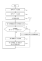
- 10 is a flowchart showing a flow of a control process in a first display mode.
- 10 is a flowchart showing a flow of a control process in a second display mode.
- 10 is a flowchart showing a flow of a control process in a second display mode.
- 10 is a flowchart showing the flow of a control process in another example of the second display mode.
- 10 is a flowchart showing the flow of a control process in another example of the second display mode.
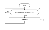
- 13 is a flowchart showing the flow of an image deletion process.
- 11 is a flowchart showing a flow of a transition process to a first display mode.
- the "vertical direction of an image” and the “horizontal direction of an image” may be set according to the content of the image.
- the vertical direction of an image may be the direction that a user recognizes as the top and bottom direction of the image based on the content of the image.
- the horizontal direction of an image may be the direction that a user recognizes as the horizontal direction of the image based on the content of the image.
- the “aspect ratio of an image” is the ratio between the vertical size and the horizontal size of the image.
- a display system 1 according to the present embodiment as shown in Fig. 1 is used at a counter.
- the counter where the display system 1 is used is, for example, a counter of a public institution such as a government or a local government, a counter of a financial institution, a counter of a medical institution, or a counter of a public transportation facility.
- the display system 1 may be used at a place other than a counter.
- the display system 1 may be used in a conference room in a business store or office of a private business operator.
- the display system 1 can support a dialogue between a first user U1 and a second user U2.
- the first user U1 is a visitor who comes to the counter.
- the first user U1 is, for example, a person with hearing impairment.
- the second user U2 is a counter clerk in charge of the counter. At such a counter, the first user U1 and the second user U2 face each other.
- the display system 1 includes a substrate 10 and a projector 20. As shown in FIG. 2, the display system 1 includes a microphone 30, an input device 40, and an electronic device 50.
- the electronic device 50 serves as a display control device in the display system 1.
- the projector 20, the microphone 30, the input device 40, and the electronic device 50 can communicate with each other via communication lines.
- the communication lines may be configured to include, for example, wired or wireless communication.
- the projector 20, the microphone 30, the input device 40, and the electronic device 50 may be configured as a single device.
- the substrate 10 is located between the first user U1 and the second user U2.
- the substrate 10 is made of, for example, a transparent material.
- the vertical length of the substrate 10 may be equal to or greater than the length of the upper body of an average person.
- the horizontal length of the substrate 10 may be several times the shoulder width of an average person.
- vinyl curtains or acrylic panels, etc. are sometimes installed between a visitor such as the first user U1 and a counter staff member such as the second user U2 to prevent splashes.
- Such vinyl curtains or acrylic panels, etc. may be used as the substrate 10.
- the substrate 10 includes surfaces 10A and 10B.
- the first user U1 is located on the surface 10B side.
- the second user U2 is located on the surface 10A side.
- the substrate 10 includes a transparent screen 11.
- the transparent screen 11 is disposed on the surface 10A side of the surface 10A, 10B of the base material 10.
- the spoken contents of the second user, etc. are projected onto the transparent screen 11 by the projector 20, as described below.
- the first user U1 who is hearing impaired, can read and understand the spoken contents of the second user U2 projected onto the transparent screen 11.
- the transparent screen 11 may be disposed at any position on the substrate 10. As an example, when the substrate 10 is located between a first user U1 and a second user U2, the transparent screen 11 may be disposed at a position on the substrate 10 that does not prevent the first user U1 and the second user U2 from seeing each other's faces. In this case, the transparent screen 11 may be disposed below the center of the substrate 10. The size of the transparent screen 11 may be set based on the amount of information to be projected onto the transparent screen 11.
- the transparent screen 11 includes a screen portion 12 and a light-shielding portion 13.
- the screen portion 12 is disposed on the surface 10A of the substrate 10.
- the light-shielding portion 13 is disposed on the screen portion 12.
- the screen unit 12 is a projector screen.
- the screen unit 12 is composed of a transparent material, such as a film, sheet, or plate, that can be attached to the base material 10.
- the screen unit 12 itself is sometimes called a "transparent screen.”
- Projection light from the projector 20 is incident on the screen unit 12.
- the screen unit 12 diffuses a portion of the incident projection light on both the input side and output side of the projection light.
- the first user U1 and the second user U2 can recognize the image projected by the projector 20 when the projection light diffused by the screen unit 12 comes into their field of vision.
- the shape of the screen portion 12 is, for example, rectangular. However, the shape of the screen portion 12 is not limited to a rectangular shape. The shape of the screen portion 12 may be any shape.
- the light shielding section 13 at least partially blocks the transmission of the projection light emitted from the projector 20.
- the light shielding section 13 blocks transmitted light of a predetermined wavelength from the projection light emitted from the projector 20.
- the light shielding section 13 is, for example, composed of a dichroic film that blocks light of a predetermined wavelength.
- the light shielding section 13 is composed of a dichroic film that blocks red light.
- the light-shielding portion 13 may be overlapped with a portion of the screen portion 12.
- the light-shielding portion 13 is disposed overlapping the surface of the screen portion 12.
- the light-shielding portion 13 may be disposed below the center of the surface of the screen portion 12.
- the shape of the light-shielding portion 13 is, for example, rectangular. However, the shape of the light-shielding portion 13 is not limited to a rectangular shape. The shape of the light-shielding portion 13 may be any shape.
- the screen unit 12 is the display unit in the display system 1. As shown in FIG. 2, the area of the screen unit 12 includes a first display area A1 and a second display area A2.
- the first display area A1 is an area of the screen unit 12 that does not overlap with the light-shielding unit 13. Projection light of characters, images, etc. is irradiated onto the first display area A1 by the projector 20. Because the first display area A1 is an area of the screen unit 12 that does not overlap with the light-shielding unit 13, both the first user U1 and the second user U2 can see the characters, images, etc. projected onto the first display area A1. In this embodiment, the first display area A1 is used by the first user U1 to view the speech content, etc. of the second user U2.
- the second display area A2 is an area where the screen unit 12 and the light-shielding unit 13 overlap. As described below, the projector 20 irradiates the second display area A2 with projection light of a predetermined wavelength that is blocked by the light-shielding unit 13. At this time, the first user U1 cannot see the characters, etc. projected in the second display area A2. However, the second user U2 can see the characters, etc. projected in the second display area A2. In this embodiment, the second display area A2 is used by the second user U2 to check the content of his or her own speech.
- the second display area A2 may be located below the first display area A1, as shown in FIG. 3 described below.
- the size of the first display area A1 and the size of the second display area A2 may be set based on the amount of information to be displayed in the first display area A1 and the second display area A2, respectively.
- 4/5 of the area of the screen unit 12 may be the first display area A1.
- 1/5 of the area of the screen unit 12 may be the second display area A2.
- the operating modes of the display system 1 include a first display mode and a second display mode.
- the first display mode is a mode in which both text and images can be displayed in the first display area A1.
- the first display area A1 includes a first area A11 and a second area A12, as shown in FIG. 3 described below. Text is displayed in the first area A11. Images are displayed in the second area A12.
- the size of the first area A11 and the size of the second area A12 in the first display area A1 may be set based on the amount of text and images displayed in the first display area A1. As an example, 2/3 of the first display area A1 may be the first area A11. 1/3 of the first display area A1 may be the second area A12.
- the second display mode is a mode in which images are displayed in a different display manner than in the first display mode.
- the second display mode is a mode in which more images or larger images can be displayed than in the first display mode.
- the first display area A1 includes a third area A13, as shown in Figures 5 to 7 described below. An image is displayed in the third area A13.
- the size of the third area A13 is the same as the size of the first display area A1. However, the size of the third area A13 may be smaller than the size of the first display area A1.
- the projector 20 is disposed on the surface 10A side of the surface 10A, 10B, of the substrate 10, as shown in FIG. 2.
- the projector 20 is disposed, for example, closer to the second user U2 than the substrate 10, as shown in FIG. 1.
- the projector 20 irradiates the projection light onto the screen unit 12 based on the control of the electronic device 50.
- the projector 20 projects characters, images, etc. onto the screen unit 12 by irradiating the projection light onto the screen unit 12.
- the microphone 30 is disposed on the side 10A of the surfaces 10A and 10B of the base material 10.
- the microphone 30 is disposed closer to the second user U2 than the base material 10 as shown in FIG. 1.
- the microphone 30 may be disposed on a desk in front of the second user U2. If the second user U2 wears a headset, the microphone 30 may be attached to the headset.
- the microphone 30 collects audio.
- the audio collected by the microphone 30 may include speech from the second user U2.
- the microphone 30 transmits data of the collected audio to the electronic device 50.
- the input device 40 is disposed on the surface 10A side of the surface 10A, 10B of the substrate 10 as shown in FIG. 2.
- the input device 40 is disposed, for example, closer to the second user U2 than the substrate 10 as shown in FIG. 1.
- the input device 40 may be disposed on a desk in front of the second user U2 as shown in FIG. 1.
- the input device 40 is composed of a keyboard or a numeric keypad, etc.
- the input device 40 accepts input from the second user U2.
- the input device 40 transmits the accepted input data to the electronic device 50.
- the electronic device 50 is, for example, a smartphone or a tablet terminal.
- the electronic device 50 is capable of communicating with the server 3 via the network 2.
- the network 2 may be any network including a mobile communication network and the Internet.
- the server 3 is, for example, a cloud server.
- the server 3 is capable of performing voice recognition.
- Server 3 is a server that can be accessed via network 2.
- Server 3 in this embodiment is a voice recognition server that provides a voice recognition service.
- the voice recognition service is a service that converts voice into text information.
- server 3 in this embodiment receives voice data, it executes voice recognition processing on the received voice data.
- the voice recognition processing is a process that converts voice data into text information.
- Server 3 executes voice recognition processing to convert the received voice data into text information.
- Server 3 transmits the converted text information to the sender of the voice data.
- Server 3 provides the voice recognition service as a paid or free service.
- the electronic device 50 includes a communication unit 51, a memory unit 52, and a control unit 53.
- the communication unit 51 is configured to include at least one communication module that can be connected to the network 2.
- the communication module is, for example, a communication module that supports mobile communication standards such as LTE (Long Term Evolution), 4G (4th Generation), or 5G (5th Generation).
- the communication unit 51 includes at least one communication module capable of communicating with the projector 20 via a communication line.
- the communication module is a communication module that corresponds to the standard of the communication line between the electronic device 50 and the projector 20.
- the standard of the communication line is a short-range wireless communication standard such as Miracast.
- the communication unit 51 is configured to include at least one communication module capable of communicating with the microphone 30 via a communication line.
- the communication module is a communication module that corresponds to the standard of the communication line between the electronic device 50 and the microphone 30.
- the standard of the communication line is a wired communication standard such as the CTIA (Cellular Telephone Industry Association) standard or the OMTP (Open Mobile Terminal Platform) standard.
- the communication unit 51 includes at least one communication module capable of communicating with the input device 40 via a communication line.
- the communication module is a communication module that corresponds to the standard of the communication line between the electronic device 50 and the input device 40.
- the standard of the communication line is, for example, a short-range wireless communication standard such as Bluetooth (registered trademark).
- the communication unit 51 may be configured to include at least one communication module capable of communicating with an IC card.
- the communication module is a communication module compatible with a short-range wireless communication standard such as NFC (near field communication) or RFID (Radio Frequency Identifier). This communication module is placed on a desk in front of the first user U1 as shown in FIG. 1.
- the memory unit 52 is configured to include at least one semiconductor memory, at least one magnetic memory, at least one optical memory, or a combination of at least two of these.
- the semiconductor memory is, for example, a RAM (Random Access Memory) or a ROM (Read Only Memory).
- the RAM is, for example, an SRAM (Static Random Access Memory) or a DRAM (Dynamic Random Access Memory).
- the ROM is, for example, an EEPROM (Electrically Erasable Programmable Read Only Memory).
- the memory unit 52 may function as a main memory device, an auxiliary memory device, or a cache memory.
- the memory unit 52 stores data used in the operation of the electronic device 50 and data obtained by the operation of the electronic device 50.
- the memory unit 52 stores system programs, application programs, embedded software, etc.
- the memory unit 52 includes a first database 52D1 and a second database 52D2.
- the first database 52D1 stores data of the first image.
- the first image may be a still image or a moving image.
- a first keyword is associated with the first image. Different first images may be associated with different first keywords.
- the vertical size of the first image is larger than the horizontal size of the first image. In other words, the first image is a so-called vertically long image.
- the aspect ratio of the first image may be set according to the size of the second area A12, etc. For example, the vertical size:horizontal size of the first image is 3:2.
- the first image is used in both the first display mode and the second display mode.
- the second database 52D2 stores data of the second image.
- the second image may be a still image or a moving image.
- a second keyword is associated with the second image. Different second keywords may be associated with different second images. Some or all of the multiple second keywords may be the same as or different from some or all of the multiple first keywords.
- the horizontal size of the second image is larger than the vertical size of the second image. In other words, the second image is a so-called landscape image.
- the aspect ratio of the second image may be set according to the size of the first display area A1, etc. For example, the vertical size:horizontal size of the second image is 2:3.
- the second image is used in the second display mode. The amount of information contained in the second image may be greater than the amount of information contained in the first image.
- the second image is, for example, a map, etc.
- the control unit 53 is configured to include at least one processor, at least one dedicated circuit, or a combination of these.
- the processor is a general-purpose processor such as a CPU (Central Processing Unit) or a GPU (Graphics Processing Unit), or a dedicated processor specialized for a specific process.
- the dedicated circuit is, for example, an FPGA (Field-Programmable Gate Array) or an ASIC (Application Specific Integrated Circuit).
- the control unit 53 executes processes related to the operation of the electronic device 50 while controlling each part of the electronic device 50.
- the control unit 53 operates in the first display mode in an initial state.
- the electronic device 50 is in the initial state immediately after starting an application program for executing the display system 1.
- the control unit 53 executes a process for acquiring character information, which will be described below.
- the control unit 53 receives voice data collected by the microphone 30 from the microphone 30 via the communication unit 51.
- the received voice data may include data of an utterance made by the second user U2.
- the control unit 53 transmits the received voice data to the server 3 via the network 2 via the communication unit 51.
- the server 3 executes a voice recognition process on the received voice data.
- the server 3 converts the voice data into character information, it transmits the converted character information to the electronic device 50 via the network 2.
- the control unit 53 receives the character information converted by voice recognition from the server 3 via the network 2 using the communication unit 51. In this embodiment, the control unit 53 receives the character information from the server 3, thereby acquiring the character information converted by voice recognition.
- control unit 53 When the control unit 53 receives the character information from the server 3 , it generates first character information and second character information based on the character information received from the server 3 .
- the first character information is character information to be displayed in the first area A11 of the first display area A1.
- the control unit 53 generates the first character information so that the character string included in the character information in the first area A11 is displayed upright as seen by the first user U1.
- "upright” means a state in which characters, etc. are displayed correctly from the left to the right as seen by the user.
- "Upright” is used in contrast to a state in which characters, etc. are inverted left to right.
- the direction in which the character string of the first character information is arranged in the first display area A1 depends on the language and the display mode of the text in the first area A11.
- the received character information is character information in Japanese.
- the text is displayed in the first area A11 in a horizontal display mode as shown in FIG. 3 described later.
- Horizontally written Japanese text is read from the left side of the text to the right side. Therefore, the control unit 53 generates the first character information so that the character string included in the received character information is arranged from the left side to the right side as seen by the first user U1, as in the first character information 60 shown in FIG. 3 described later.
- the control unit 53 may generate the first character information so that the character string contained in the character information is readable by the first user U1.
- the second character information is character information to be displayed in the second display area A2.
- the control unit 53 generates the second character information such that the character string included in the character information is displayed upright in the second display area A2 when viewed by the second user U2, as in the second character information 61 shown in FIG. 4 described below.
- the second character information displayed in the second display area A2 and the first character information displayed in the first display area A1 may be in a left-right mirrored relationship.
- the control unit 53 may generate the second character information such that the character string included in the character information is readable when viewed by the second user U2.
- the control unit 53 executes a display process for the first character information and the second character information.
- This display process is a process for displaying the first character information in the first area A11 and the second character information in the second display area A2.
- the control unit 53 causes the projector 20 to irradiate the projection light of the first character information onto the first area A11 by transmitting a control signal to the projector 20 via the communication unit 51.
- the wavelength of the projection light of the first character information may be set taking into consideration the visibility of characters, etc. in the first area A11.
- the control unit 53 causes the projector 20 to irradiate the projection light of the first character information onto the first area A11, thereby displaying the first character information in the first area A11.
- the control unit 53 causes the projector 20 to irradiate the projection light of the second character information onto the second display area A2 by sending a control signal to the projector 20 via the communication unit 51.
- the projection light of the second character information is light of a predetermined wavelength that is blocked by the light blocking unit 13. For example, if the light blocking unit 13 is composed of a dichroic film that blocks red light, the projection light of the second character information will have a wavelength of red light.
- the control unit 53 causes the projector 20 to irradiate the projection light of the second character information onto the second display area A2, thereby displaying the second character information in the second display area A2.
- FIG. 3 shows the configuration of the first display area A1 and the second display area A2 as viewed from the first user U1.
- FIG. 4 shows the configuration of the first display area A1 and the second display area A2 as viewed from the second user U2.
- the control unit 53 receives character information "Good morning” from the server 3.
- the control unit 53 generates the first character information 60 so that the character string "Good morning” is arranged from the left to the right as viewed from the first user U1 as shown in FIG. 3.
- the control unit 53 generates the second character information 61 so that the character string "Good morning” is arranged from the left to the right as viewed from the second user U2 as shown in FIG. 4.
- the projection light of the second character information 61 is light of a predetermined wavelength that is blocked by the light blocking unit 13. Therefore, as shown in FIG. 3, the first user U1 cannot see the character "Good morning” projected on the second display area A2.
- control unit 53 when the control unit 53 receives character information from the server 3, it refers to the first database 52D1 and determines whether or not the received character information includes a first keyword. If the control unit 53 determines that the received character information includes the first keyword, it obtains data of a first image associated with the first keyword from the first database 52D1.
- control unit 53 When the control unit 53 acquires the data of the first image from the first database 52D1, it displays the acquired data of the first image in the second area A12. As an example of this process, the control unit 53 causes the projector 20 to irradiate the projection light of the first image onto the second area A12 by transmitting a control signal to the projector 20 via the communication unit 51.
- the wavelength of the projection light of the first image may be set taking into consideration the ease of viewing the image in the second area A12.
- the control unit 53 displays the first image in the second area A12 by causing the projector 20 to irradiate the projection light of the first image onto the second area A12. For example, in the configuration shown in FIG. 3 and FIG. 4, the first image 62 is displayed in the second area A12.
- the first condition is a condition for transitioning the operation mode of the display system 1 from the first display mode to the second display mode.
- the first condition may be set in consideration of user convenience.
- the first condition may be a condition that a predetermined input is received.
- the predetermined input may be, for example, an input of an instruction to transition to the second display mode.
- the second user U2 may want to display an image such as a map with a large amount of information in the first display area A1.
- the second user U2 may input an input of an instruction to transition to the second display mode to the input device 40.
- the input device 40 may transmit the received input data of the instruction to transition to the second display mode to the electronic device 50.
- the control unit 53 may receive the input of the instruction to transition to the second display mode by receiving the input data of the instruction to transition to the second display mode from the input device 40 via the communication unit 51.
- the control unit 53 When the control unit 53 receives the input of the instruction to transition to the second display mode, it transitions the operation mode of the display system 1 from the first display mode to the second display mode.
- the control unit 53 may receive the predetermined input via the microphone 30.
- the predetermined input may be an input by voice.
- the first condition may be a condition that the status information of the first user U1 indicates a desire to use the second display mode.
- the first user U1 may want to receive an explanation from the second user U2 only through an image.
- the first user U1 may write in advance in an IC card that he/she owns that he/she desires to use the second display mode.
- This IC card may be issued by a public institution that uses the display system 1 as a window.
- the first user U1 holds the IC card over the communication module of the communication unit 51 before starting a dialogue with the second user U2.
- the control unit 53 executes short-range wireless communication with the IC card of the first user U1 through the communication unit 51.
- the control unit 53 executes short-range wireless communication with the IC card of the first user U1 through the communication unit 51, thereby acquiring the desire to use the second display mode written in the IC card as the status information of the first user U1.
- the control unit 53 acquires the request to use the second display mode written in the IC card, it transitions the operation mode of the display system 1 from the first display mode to the second display mode.
- control unit 53 determines whether or not the first condition is satisfied while the first image is being displayed in the second area A12.
- the control unit 53 When transitioning to the second display mode, if the control unit 53 determines that the first condition is satisfied when the first image is not being displayed in the second area A12, it initializes the first display area A1. For example, as shown in FIG. 5, the control unit 53 initializes the first display area A1 by deleting the first character information 60 shown in FIG. 3 from the first area A11.
- the configuration shown in FIG. 5 is the configuration of the first display area A1 and the second display area A2 as viewed from the first user U1.
- control unit 53 determines whether or not a second image associated with a second keyword that is the same as the first keyword associated with the first image being displayed has been saved.
- the control unit 53 refers to the second database 52D2 and determines whether or not a second image associated with a second keyword that is the same as the first keyword associated with the first image being displayed has been saved.
- control unit 53 determines that a second image associated with the same second keyword as the first keyword associated with the first image being displayed in the second area A12 is stored, the control unit 53 acquires data of the second image from the second database 52D2. Upon acquiring the data of the second image, the control unit 53 deletes the first image being displayed in the second area A12 and displays the acquired second image in the third area A13. For example, the control unit 53 displays the second image 70 in the third area A13 as shown in FIG. 6.
- control unit 53 determines that a second image associated with the same second keyword as the first keyword associated with the first image being displayed in the second area A12 is not stored, the control unit 53 displays the first image being displayed in the second area A12 in the third area A13. For example, as shown in FIG. 7, the control unit 53 displays the first image 71 in the third area A13. The control unit 53 displays the first image 71 in the center of the third area A13. However, the control unit 53 may display the first image 71 in any location other than the center of the third area A13.
- the control unit 53 executes the character information acquisition process in the second display mode in the same or similar manner as in the first display mode.
- the control unit 53 receives new character information from the server 3
- the control unit 53 refers to the second database 52D2 and determines whether the newly received character information includes the second keyword.
- the control unit 53 acquires new second image data associated with the second keyword from the second database 52D2.
- the control unit 53 preferentially displays the new second image in the third area A13 of the first display area A1.
- control unit 53 preferentially displays the new second image in the third area A13, deletes the first or second image being displayed in the third area A13 of the first display area A1, and displays the new second image in the third area A13.
- preferentially displaying the new second image in the third area A13 is not limited to this.
- the control unit 53 may display a new second image by superimposing it on a portion of the first image or second image that is being displayed.
- the control unit 53 may obtain new data of a first image corresponding to the first keyword from the first database 52D1.
- the control unit 53 may display the new data of the first image in the third area A13 of the first display area A1.
- control unit 53 may determine whether or not there is free space in the third area A13 before displaying a new first image in the third area A13.
- the free space is space in which the first image can be displayed.
- the control unit 53 may determine whether or not there is free space in the third area A13 by calculating the maximum number of first images that can be displayed in the third area A13.
- the control unit 53 may calculate the maximum number of first images that can be displayed in the third area A13 from the aspect ratio of the first image and the horizontal and vertical sizes of the third area A13.
- the control unit 53 determines that there is free space in the third area A13 before displaying a new first image in the third area A13
- the control unit 53 displays the new first image in the third area A13 together with the first image currently being displayed.
- the control unit 53 determines that there is free space in the third area A13.
- the control unit 53 displays a new first image 72 together with the first image currently being displayed 71, as shown in FIG. 8.
- the control unit 53 may display a first image that was displayed going back in time as one approaches the left side of the third area A13.
- the control unit 53 may also display multiple first images centered around the center of the third area A1. However, the control unit 53 may display the first image currently being displayed and the new first image, i.e., multiple first images, at any location in the third area A13.
- control unit 53 determines that there is no free space in the third area A13 before displaying a new first image in the third area A13, it deletes one of the first images currently being displayed, and displays the new first image in the third area A13.
- the control unit 53 may delete the first image that was displayed most recently among the first images currently being displayed. For example, in the configuration shown in FIG. 9, the control unit 53 determines that there is no free space in the third area A13. Among the first images 71, 72, and 73 currently being displayed in the third area A13, the first image 71 is the image that was displayed most recently. In the configuration shown in FIG. 9, the control unit 53 deletes the first image 71 among the first images 71 to 73 currently being displayed, and displays the new first image in the third area A13.
- the second user U2 may input an image deletion instruction to the input device 40 in the first display mode or the second display mode.
- the image deletion instruction is an input instructing to delete the first image or the second image being displayed in the first display area A1.
- the image deletion instruction may specify the image to be deleted from the first display area A1.
- the input device 40 receives the image deletion instruction input, it may transmit data of the image deletion instruction input to the electronic device 50.
- the control unit 53 may accept input of an instruction to delete an image from the second user U2 by receiving input data of an instruction to delete an image from the input device 40 via the communication unit 51.
- the control unit 53 may delete the image from the first display area A1 in accordance with this input.
- the second condition is a condition for shifting the operation mode of the display system 1 from the second display mode to the first display mode.
- the second condition may be set in consideration of user convenience.
- the second condition may be a condition that a predetermined input is received.
- the predetermined input may be, for example, an input of an instruction to transition to the first display mode.
- the second user U2 may want to return the operation mode of the display system 1 to the first display mode after explaining to the first user U1 using the second display mode.
- the second user U2 may input an input of an instruction to transition to the first display mode to the input device 40.
- the input device 40 may transmit the received input data of the instruction to transition to the first display mode to the electronic device 50.
- the control unit 53 may receive the input of an instruction to transition to the first display mode by receiving the input data of the instruction to transition to the first display mode from the input device 40 via the communication unit 51.
- the control unit 53 transitions the operation mode of the display system 1 from the second display mode to the first display mode.
- the control unit 53 may receive the predetermined input via the microphone 30 in the same or similar manner as the first condition.
- the second condition may be a condition that the status information of the first user U1 does not indicate a desire to use the second display mode.
- the first user U1 may not particularly desire to use the second display mode.
- the first user U1 does not need to write in the IC card he/she possesses that he/she desires to use the second display mode as described above.
- the first user U1 does not place the IC card on the communication module of the communication unit 51 before starting a dialogue with the second user U2, for example.
- the control unit 53 detects that the desire to use the second display mode is not written in the IC card by performing short-range wireless communication with the IC card of the first user U1 through the communication unit 51 as described above.
- control unit 53 When the control unit 53 detects that the desire to use the second display mode is not written in the IC card of the first user U1, it may determine that the condition that the status information of the first user U1 does not indicate a desire to use the second display mode is satisfied. That is, when the control unit 53 detects that the first user U1 has not written a request to use the second display mode on his/her IC card, the control unit 53 may switch the operation mode of the display system 1 from the second display mode to the first display mode.
- the second user U2 may leave the operation mode of the display system 1 in the second display mode after explaining the second display mode to the visitor before the first user U1. Even if the second user U2 leaves the operation mode of the display system 1 in the second display mode in this way, the operation mode of the display system 1 can be switched to the first display mode according to the status information of the first user U1.
- Fig. 10 is a flowchart showing the flow of the control process in the first display mode.
- the control process shown in Fig. 10 corresponds to an example of a control method according to the present embodiment.
- the control unit 53 receives an input indicating an instruction to execute character display on the transparent screen 11 from the input device 40 via the communication unit 51
- the control unit 53 starts the process of step S1 shown in Fig. 10.
- This input is input to the input device 40 by the second user U2.
- the operation mode of the display system 1 is the first display mode.
- the control unit 53 receives voice data collected by the microphone 30 from the microphone 30 via the communication unit 51 (step S1).
- the control unit 53 transmits the voice data received in the process of step S1 to the server 3 via the network 2 via the communication unit 51 (step S2).
- the control unit 53 receives text information converted by voice recognition from the server 3 via the network 2 via the communication unit 51 (step S3). In parallel with the process of step S4 and onwards, the control unit 53 repeatedly executes the processes of steps S1 to S3.
- the control unit 53 generates the first character information and the second character information based on the character information received from the server 3 in the processing of step S3 (step S4).
- the control unit 53 refers to the first database 52D1 and determines whether or not the first keyword is included in the character information received in the processing of step S3 (step S5). If the control unit 53 determines that the received character information does not include the first keyword (step S5: NO), the control unit 53 proceeds to the processing of step S6. On the other hand, if the control unit 53 determines that the received character information includes the first keyword (step S5: YES), the control unit 53 proceeds to the processing of step S7.
- control unit 53 displays the first character information generated in the process of step S4 in the first area A11 of the first display area A1, and displays the second character information generated in the process of step S4 in the second display area A2.
- control unit 53 retrieves data of the first image associated with the first keyword contained in the received text information from the first database 52D1.
- control unit 53 displays the first character information generated in the process of step S4 in the first area A11 of the first display area A1, and displays the second character information generated in the process of step S4 in the second display area A2.
- the control unit 53 displays the first image acquired in the process of step S7 in the second area A12 of the first display area A1.
- control unit 53 After processing step S7 or step S8, the control unit 53 returns to processing step S4.
- control unit 53 when the control unit 53 receives, for example, an input from the input device 40 via the communication unit 51 indicating the stopping of character display on the transparent screen 11, the control unit 53 ends the control processing shown in FIG. 10. This input is input to the input device 40 by the second user U2.
- FIG. 11 and 12 are flowcharts showing the flow of control processing in the second display mode.
- the control processing shown in Fig. 11 and Fig. 12 corresponds to an example of a control method according to the present embodiment.
- the control unit 53 executes the processing of step S11 shown in Fig. 11 in parallel with the processing of steps S1 to S8 shown in Fig. 10.
- the control unit 53 repeatedly executes the processing of steps S1 to S3 in parallel with the processing of step S11 and subsequent steps.
- the control unit 53 determines whether or not the first condition is satisfied (step S11). If the control unit 53 determines that the first condition is satisfied (step S11: YES), the control unit 53 proceeds to the process of step S12. On the other hand, if the control unit 53 does not determine that the first condition is satisfied (step S11: NO), the control unit 53 executes the process of step S11 again.
- step S12 the control unit 53 transitions the operation mode of the display system 1 from the first display mode to the second display mode.
- step S13 the control unit 53 determines whether or not the first condition is satisfied while the first image is being displayed in the second area A12. For example, if the process of step S8 shown in FIG. 10 has been executed before the process of step S11, the first condition may be satisfied while the first image is being displayed.
- control unit 53 determines that the first condition is satisfied when the first image is not being displayed in the second area A12 (step S13: NO), it initializes the first display area A1 (step S14). On the other hand, if the control unit 53 determines that the first condition is satisfied while the first image is being displayed in the second area A12 (step S13: YES), it proceeds to the processing of step S15.
- step S15 the control unit 53 refers to the second database 52D2 and determines whether or not a second image associated with the same second keyword as the first keyword associated with the first image being displayed has been saved. If the control unit 53 determines that the second image has been saved (step S15: YES), the control unit 53 proceeds to the process of step S17. On the other hand, if the control unit 53 determines that the second image has not been saved (step S15: NO), the control unit 53 proceeds to the process of step S16.
- step S16 the control unit 53 displays the first image being displayed in the second area A12 in the third area A13. For example, as shown in FIG. 7, the control unit 53 displays the first image 71 in the third area A13.
- step S17 the control unit 53 obtains from the second database 52D2 data on a second image associated with the same second keyword as the first keyword associated with the first image being displayed in the second area A12.
- the control unit 53 deletes the first image being displayed in the second area A12 (step S18), and displays the second image obtained in the process of step S17 in the third area A13 (step S19).
- the control unit 53 displays the second image 70 in the third area A13, as shown in FIG. 6.
- step S14 After executing the process of step S14, step S16, or step S19, the control unit 53 proceeds to the process of step S20 shown in FIG. 12.
- control unit 53 When the control unit 53 newly executes the process of step S3, that is, when it newly receives character information from the server 3, it executes the process of step S20.
- the control unit 53 refers to the second database 52D2 and determines whether the newly received character information from the server 3 includes the second keyword (step S20). If the control unit 53 determines that the newly received character information includes the second keyword (step S20: YES), it proceeds to the process of step S21. On the other hand, if the control unit 53 determines that the newly received character information does not include the second keyword (step S20: NO), it executes the process of step S20 again.
- control unit 53 obtains data of a second image associated with a second keyword contained in the newly received text information from the second database 52D2.
- the control unit 53 determines whether or not the first image or the second image is being displayed in the third area A13. If the process of step S16 or step S19 is performed before the process of step S22, the first image or the second image is being displayed in the third area A13 of the first display area A1. If the process of step S14 is performed before the process of step S22, neither the first image nor the second image is being displayed in the third area A13 of the first display area A1.
- step S22 determines that the first image or the second image is being displayed in the third area A13 (step S22: YES)
- the control unit 53 proceeds to the process of step S23.
- the control unit 53 determines that neither the first image nor the second image is being displayed in the third area A13 of the first display area A1 (step S22: NO)
- the control unit 53 proceeds to the process of step S24.
- control unit 53 deletes the first image or the second image being displayed from the third area A13.
- control unit 53 displays the second image acquired in the process of step S21 in the third area A13.
- control unit 53 when the control unit 53 receives, for example, an input from the input device 40 via the communication unit 51 indicating the stopping of character display on the transparent screen 11, the control unit 53 ends the control processing shown in Figures 11 and 12. This input is input to the input device 40 by the second user U2.
- FIG. 13 and 14 are flowcharts showing the flow of control processing in another example of the second display mode.
- the control processing shown in Fig. 13 and 14 corresponds to an example of a control method according to the present embodiment.
- the control unit 53 starts the processing of step S31 shown in Fig. 13 after executing the processing of step S19 shown in Fig. 11.
- the control unit 53 repeatedly executes the processing of steps S1 to S3 shown in Fig. 10 in parallel with the processing of step S31 and subsequent steps.
- control unit 53 When the control unit 53 newly executes the process of step S3, that is, when new text information is received from the server 3, the control unit 53 executes the process of step S31.
- step S31 the control unit 53 refers to the second database 52D2 and determines whether or not the second keyword is included in the character information newly received from the server 3. If the control unit 53 determines that the newly received character information includes the second keyword (step S31: YES), the control unit 53 proceeds to the process of step S32. On the other hand, if the control unit 53 determines that the newly received character information does not include the second keyword (step S31: NO), the control unit 53 proceeds to the process of step S36.
- the control unit 53 executes the processes of steps S32, S33, S34, and S35 in the same or similar manner as the processes of steps S21, S22, S23, and S24 shown in FIG. 12. After executing the process of step S35, the control unit 53 returns to the process of step S31.
- step S36 the control unit 53 refers to the first database 52D1 and determines whether or not the newly received character information from the server 3 includes the first keyword.
- the control unit 53 executes the process of step S36 on the same character information as the character information on which the process of step S31 was executed. If the control unit 53 determines that the newly received character information includes the first keyword (step S36: YES), it proceeds to the process of step S37. On the other hand, if the control unit 53 determines that the newly received character information does not include the first keyword (step S36: NO), it returns to the process of step S31.
- control unit 53 obtains data of the first image associated with the first keyword contained in the newly received text information from the first database 52D1.
- step S38 the control unit 53 determines whether or not the second image is being displayed in the third area A13. If the control unit 53 determines that the second image is being displayed in the third area A13 (step S38: YES), it deletes the second image from the third area A13 (step S39) and proceeds to the process of step S40. On the other hand, if the control unit 53 determines that the second image is not being displayed in the third area A13 (step S38: NO), it proceeds to the process of step S40.
- control unit 53 displays the first image acquired in the process of step S37 in the third area A13.
- step S40 After executing the process of step S40, the control unit 53 proceeds to the process of step S41 shown in FIG. 14.
- control unit 53 When the control unit 53 newly executes the process of step S3, that is, when new text information is received from the server 3, it executes the process of step S41.
- step S41 the control unit 53 refers to the second database 52D2 and determines whether or not the second keyword is included in the character information newly received from the server 3. If the control unit 53 determines that the newly received character information includes the second keyword (step S41: YES), the control unit 53 proceeds to the process of step S32 shown in FIG. 13. On the other hand, if the control unit 53 determines that the newly received character information does not include the second keyword (step S41: NO), the control unit 53 proceeds to the process of step S42.
- step S42 the control unit 53 refers to the first database 52D1 and determines whether or not the first keyword is included in the character information newly received from the server 3.
- the control unit 53 executes the process of step S42 on the same character information as the character information on which the process of step S41 was executed. If the control unit 53 determines that the newly received character information includes the first keyword (step S42: YES), it proceeds to the process of step S43. On the other hand, if the control unit 53 determines that the newly received character information does not include the first keyword (step S42: NO), it returns to the process of step S31 shown in FIG. 13.
- control unit 53 obtains data of the first image associated with the first keyword contained in the newly received text information from the first database 52D1.
- step S44 the control unit 53 determines whether or not there is free space in the third area A13. If the control unit 53 determines that there is free space in the third area A13 (step S44: YES), the control unit 53 proceeds to the process of step S46. If the control unit 53 determines that there is no free space in the third area A13 (step S44: NO), the control unit 53 deletes one of the first images being displayed from the third area A13 (step S45), and proceeds to the process of step S46.
- step S46 the control unit 53 displays the first image acquired in the process of step S43 in the third area A13. After executing the process of step S46, the control unit 53 returns to the process of step S41.
- step S44 determines that there is free space in the third area A13 (step S44: YES)
- the control unit 53 displays a new first image in the third area A13 together with the first image currently being displayed by the process of step S46.
- the control unit 53 displays the first image 72 together with the first image 71 currently being displayed, as shown in FIG. 8.
- control unit 53 determines that there is no free space in the third area A13 (step S44: NO), it deletes one of the first images being displayed and displays a new first image in the third area A13 by processing steps S45 and S46. For example, in the configuration shown in FIG. 9, the control unit 53 deletes the first image 71 from the first images 71 to 73 being displayed and displays a new first image in the third area A13.
- control unit 53 when the control unit 53 receives, for example, an input from the input device 40 via the communication unit 51 indicating the stopping of character display on the transparent screen 11, the control unit 53 ends the control processing shown in Figures 11 and 12. This input is input to the input device 40 by the second user U2.
- Fig. 15 is a flowchart showing the flow of an image deletion process.
- the image deletion process shown in Fig. 15 corresponds to an example of a control method according to this embodiment.
- the control unit 53 may execute the process of step S51 shown in Fig. 15 in parallel with the processes of steps S1 to S8 shown in Fig. 10, the processes of steps S11 to S24 shown in Figs. 11 and 12, or the processes of steps S31 to S46 shown in Figs. 13 and 14.
- the control unit 53 determines whether or not input of an instruction to delete an image has been received from the second user U2 (step S51). If the control unit 53 does not determine that input of an instruction to delete an image has been received from the second user U2 (step S51: NO), it executes the process of step S51 again. On the other hand, if the control unit 53 determines that input of an instruction to delete an image has been received (step S51: YES), it deletes the image from the first display area A1 in accordance with this input (step S52). After executing the process of step S52, the control unit 53 returns to the process of step S51.
- Fig. 16 is a flowchart showing the flow of the process of transitioning to the first display mode.
- the process of transitioning to the first display mode shown in Fig. 16 corresponds to an example of a control method according to the present embodiment.
- the control unit 53 may execute the process of step S61 shown in Fig. 16 in parallel with the processes of steps S11 to S24 shown in Figs. 11 and 12 or the processes of steps S31 to S46 shown in Figs. 13 and 14.
- the control unit 53 determines whether or not the second condition is satisfied (step S61). If the control unit 53 determines that the second condition is satisfied (step S61: YES), the control unit 53 proceeds to the process of step S62. On the other hand, if the control unit 53 does not determine that the second condition is satisfied (step S61: NO), the control unit 53 executes the process of step S61 again.
- step S62 the control unit 53 transitions the operation mode of the display system 1 from the second display mode to the first display mode. After executing the process of step S62, the control unit 53 proceeds to the process of step S4 shown in FIG. 10. In the process of step S4, the control unit 53 generates first character information and second character information from the acquired character information. After executing the process of step S4, the control unit 53 determines whether the character information processed in step S4 includes the first keyword (step S5).
- control unit 53 transitions the operation mode of display system 1 from the first display mode to the second display mode. Furthermore, in the second display mode, control unit 53 displays an image in first display area A1 serving as the display unit of display system 1 in a display form different from that in the first display mode. As the display form of an image differs between the first display mode and the second display mode in this manner, the operation mode of display system 1 can be transitioned to the first display mode or the second display mode depending on the state of the dialogue between first user U1 and second user U2. Thus, according to this embodiment, it is possible to improve the technology for displaying images on a display unit.
- the first condition may be a condition that a specified input has been received.
- the second user U2 may input an instruction to transition to the second display mode as the specified input to the input device 40, as described above.
- the operation mode of the display system 1 can be transitioned to the second display mode at a timing that is convenient for the second user U2. Therefore, the convenience of the second user U2 can be improved.
- the first condition may be a condition that the status information of the first user U1 indicates a desire to use the second display mode.
- the first display mode may be a mode capable of displaying text information and images.
- the first display mode may be a mode in which the first text information is displayed in the first area A11 and the first image is displayed in the second area A12, as shown in FIG. 3.
- the first display mode that displays the text information and the image is highly convenient depending on the situation of the dialogue between the first user U1 and the second user U2.
- control unit 53 may generate the first character information in the first display mode such that a character string included in the character information received from the server 3 is displayed upright when viewed by the first user U1.
- control unit 53 may generate the first character information 60 as shown in FIG. 3. This configuration can improve the convenience for the first user U1.
- the control unit 53 may determine whether or not a second image corresponding to the same second keyword as the first keyword corresponding to the first image being displayed has been saved. When the control unit 53 determines that a second image has not been saved, the control unit 53 may display the first image in the second display mode. By displaying the first image when a second image has not been saved, the first display area A1 can be used efficiently.
- the control unit 53 may display a new first image corresponding to the first keyword included in the newly acquired character information. In this way, by displaying a new first image when the newly acquired character information does not include the second keyword but does include the first keyword, the first display area A1 can be used efficiently.
- control unit 53 may determine whether or not there is free space in the third area A13 serving as the display unit before displaying a new first image. If the control unit 53 determines that there is free space in the third area A13, it may display the new first image in the third area A13 together with the first image currently being displayed. With this configuration, the first display area A1 can be used without waste.
- the control unit 53 when the control unit 53 determines that there is no free space in the third area A13 serving as the display unit, it may delete one of the first images being displayed and display a new first image in the third area A13. By deleting one of the first images being displayed and displaying a new first image when there is no free space, a new first image corresponding to the latest dialogue between the first user U1 and the second user U2 is displayed in the third area A13. With this configuration, it is possible to improve the convenience of the first user U1 and the second user U2.
- the control unit 53 when the control unit 53 deletes one of the first images being displayed when it determines that there is no free space in the third area A13 in another example of the second display mode, the control unit 53 may delete the first image that was displayed most recently among the first images being displayed. Among the first images being displayed, the first image that was displayed most recently may have reduced importance in the dialogue between the first user U1 and the second user U2. By deleting the first image that was displayed most recently, the possibility of impairing convenience for the first user U1 and the second user U2 is reduced.
- control unit 53 may determine whether or not there is free space in the third area A13 by calculating the maximum number of first images that can be displayed in the third area A13 as the display unit. With this configuration, the control unit 53 can more easily determine whether or not there is free space in the third area A13.
- control unit 53 may transition the operation mode of the display system 1 from the second display mode to the first display mode when the second condition is satisfied while the display system 1 is in the second display mode.
- the operation mode of the display system 1 can be transitioned to the first display mode depending on the state of the dialogue between the first user U1 and the second user U2.
- each functional unit, each means, each step, etc. can be added to other embodiments so as not to be logically inconsistent, or replaced with each functional unit, each means, each step, etc. of other embodiments.
- multiple functional units, each means, each step, etc. can be combined into one or divided.
- each of the above-described embodiments of the present disclosure is not limited to being implemented faithfully according to each of the described embodiments, but may be implemented by combining each feature or omitting some features as appropriate.
- the server 3 is described as executing the voice recognition process.
- any device other than the server 3 may execute the voice recognition process.
- the electronic device 50 may execute the voice recognition process.
- a general-purpose computer functions as the electronic device 50 according to the above-described embodiment.
- a program describing the processing content that realizes each function of the electronic device 50 according to the above-described embodiment is stored in the memory of the general-purpose computer, and the program is read and executed by a processor.
- the present disclosure can also be realized as a program executable by a processor, or a non-transitory computer-readable medium that stores the program.
- each embodiment of the present disclosure may be arranged in the same hardware or different hardware as appropriate.
- the microphone 30 according to each embodiment of the present disclosure may be included in the same hardware as the electronic device 50 or the projector 20.
- the input device 40 according to each embodiment of the present disclosure may be included in the same hardware as the electronic device 50 or the projector 20.
- Some or all of the communication unit 51, memory unit 52, and control unit 53 according to each embodiment of the present disclosure may be included in the projector 20.
- the display unit of the present disclosure is not limited to a configuration including a transparent screen.
- the display unit may include, for example, a transparent organic electroluminescent display (OLED: Organic Light Emitting Diode) in which light-emitting elements are arranged within a transparent substrate.
- OLED Organic Light Emitting Diode
- the first user U1 is described as holding the IC card over the communication module of the communication unit 51.
- the first user U1 does not have to hold the IC card over the communication module of the communication unit 51.
- the control unit 53 may receive, via the communication unit 15, a request to use the second display mode written on the IC card, etc.
- the program comprises: A display control device includes: Obtaining text information converted by speech recognition; operating in a first display mode in which an image corresponding to a keyword included in the character information is displayed on a display unit located between a first user and a second user; transitioning from the first display mode to a second display mode when a first condition is satisfied while in the first display mode; In the second display mode, the image is displayed on the display unit in a display manner different from that in the first display mode.
- the first condition may be a condition that a predetermined input has been received.
- the first condition may be a condition that status information of the first user indicates a desire to use the second display mode.
- the first display mode may be a mode in which the text information and the image can be displayed.
- the second display mode may be a mode capable of displaying more images or larger images than the first display mode.
- the process may include, in the first display mode, displaying the image by displaying a first image corresponding to a first keyword included in the character information.
- the process includes displaying first character information in the first display mode as the displaying of the character information;
- the first character information may be generated such that a character string included in the character information is displayed upright when viewed by the first user.
- the process may include, in the second display mode, displaying the image by displaying a second image corresponding to a second keyword included in the character information.
- the process comprises: determining whether a second image corresponding to a second keyword that is the same as the first keyword is stored when the first condition is satisfied during display of the first image; When it is determined that the second image is stored, displaying the image in the second display mode may include displaying the second image.
- the processing may include, when it is determined that the second image has not been saved, displaying the first image in the second display mode as the display of the image.
- the processing may include, when the character information is newly acquired in the second display mode, preferentially displaying a new second image corresponding to a second keyword contained in the newly acquired character information.
- the processing may include, in the second display mode, when the newly acquired character information does not include a second keyword but includes a first keyword, displaying a new first image corresponding to the first keyword included in the newly acquired character information.
- the process comprises: determining whether or not there is free space on the display unit before displaying the new first image; When it is determined that there is free space on the display unit, the new first image may be displayed on the display unit together with the first image currently being displayed.
- the process comprises: determining whether there is free space on the display unit before displaying the new first image; When it is determined that there is no free space on the display unit, the method may include deleting any one of the first images being displayed and displaying the new first image on the display unit.
- the process may include, as deleting any one of the first images currently being displayed, deleting a first image that was displayed most recently among the first images currently being displayed.
- the process comprises: determining whether or not there is free space on the display unit by calculating a maximum number of the first images that can be displayed on the display unit;
- the method may include calculating a maximum number of first images that can be displayed on the display unit based on an aspect ratio of the first images and a horizontal size and a vertical size of the display unit.
- a vertical size of the first image is larger than a horizontal size of the first image
- a horizontal size of the second image may be greater than a vertical size of the second image
- the process may include transitioning from the second display mode to the first display mode when a second condition is satisfied in the second display mode.
- a display control device includes: a control unit that operates in a first display mode in which character information converted by voice recognition is acquired and an image corresponding to a keyword included in the character information is displayed on a display unit located between a first user and a second user, and that transitions from the first display mode to a second display mode when a first condition is satisfied while in the first display mode;
- the control unit is In the second display mode, the image is displayed on the display unit in a display manner different from that in the first display mode.
- the control method includes: Obtaining text information converted by speech recognition; operating in a first display mode in which an image corresponding to a keyword included in the character information is displayed on a display unit located between a first user and a second user; transitioning from the first display mode to a second display mode when a first condition is satisfied while in the first display mode; In the second display mode, the image is displayed on the display unit in a display manner different from that in the first display mode.
- references such as “first” and “second” are identifiers for distinguishing the configuration.
- Configurations distinguished by descriptions such as “first” and “second” in this disclosure can exchange numbers in the configuration. For example, a first user can exchange identifiers “first” and “second” with a second user. The exchange of identifiers is performed simultaneously. The configurations remain distinguished even after the exchange of identifiers. Identifiers may be deleted. A configuration from which an identifier has been deleted is distinguished by a code. Descriptions of identifiers such as “first” and “second” in this disclosure should not be used solely to interpret the order of the configuration or to justify the existence of an identifier with a smaller number.
Landscapes
- Engineering & Computer Science (AREA)
- Multimedia (AREA)
- Human Computer Interaction (AREA)
- Health & Medical Sciences (AREA)
- Audiology, Speech & Language Pathology (AREA)
- Signal Processing (AREA)
- Physics & Mathematics (AREA)
- Theoretical Computer Science (AREA)
- Computational Linguistics (AREA)
- Acoustics & Sound (AREA)
- General Health & Medical Sciences (AREA)
- General Engineering & Computer Science (AREA)
- General Physics & Mathematics (AREA)
- Controls And Circuits For Display Device (AREA)
- User Interface Of Digital Computer (AREA)
Priority Applications (3)
| Application Number | Priority Date | Filing Date | Title |
|---|---|---|---|
| JP2025502289A JPWO2024176898A1 (https=) | 2023-02-24 | 2024-02-13 | |
| CN202480008623.5A CN120569702A (zh) | 2023-02-24 | 2024-02-13 | 程序、显示控制装置以及控制方法 |
| EP24760200.6A EP4671937A1 (en) | 2023-02-24 | 2024-02-13 | PROGRAM, DISPLAY CONTROL DEVICE AND CONTROL METHOD |
Applications Claiming Priority (2)
| Application Number | Priority Date | Filing Date | Title |
|---|---|---|---|
| JP2023027795 | 2023-02-24 | ||
| JP2023-027795 | 2023-02-24 |
Publications (1)
| Publication Number | Publication Date |
|---|---|
| WO2024176898A1 true WO2024176898A1 (ja) | 2024-08-29 |
Family
ID=92500817
Family Applications (1)
| Application Number | Title | Priority Date | Filing Date |
|---|---|---|---|
| PCT/JP2024/004880 Ceased WO2024176898A1 (ja) | 2023-02-24 | 2024-02-13 | プログラム、表示制御装置及び制御方法 |
Country Status (4)
| Country | Link |
|---|---|
| EP (1) | EP4671937A1 (https=) |
| JP (1) | JPWO2024176898A1 (https=) |
| CN (1) | CN120569702A (https=) |
| WO (1) | WO2024176898A1 (https=) |
Citations (5)
| Publication number | Priority date | Publication date | Assignee | Title |
|---|---|---|---|---|
| JP2017021541A (ja) * | 2015-07-09 | 2017-01-26 | シャープ株式会社 | コミュニケーション支援システム及びプログラム |
| WO2018025339A1 (ja) | 2016-08-03 | 2018-02-08 | マクセル株式会社 | 表示装置及び表示方法 |
| WO2019150996A1 (ja) * | 2018-01-30 | 2019-08-08 | パナソニックIpマネジメント株式会社 | 言語提示装置、言語提示方法、及び言語提示プログラム |
| JP2022098934A (ja) * | 2020-12-22 | 2022-07-04 | 株式会社Jvcケンウッド | パーティション表示装置、パーティション表示方法、およびパーティション表示プログラム |
| WO2022239152A1 (ja) * | 2021-05-12 | 2022-11-17 | 日本電信電話株式会社 | 情報提示装置、情報提示方法、及びプログラム |
-
2024
- 2024-02-13 CN CN202480008623.5A patent/CN120569702A/zh active Pending
- 2024-02-13 JP JP2025502289A patent/JPWO2024176898A1/ja active Pending
- 2024-02-13 WO PCT/JP2024/004880 patent/WO2024176898A1/ja not_active Ceased
- 2024-02-13 EP EP24760200.6A patent/EP4671937A1/en active Pending
Patent Citations (5)
| Publication number | Priority date | Publication date | Assignee | Title |
|---|---|---|---|---|
| JP2017021541A (ja) * | 2015-07-09 | 2017-01-26 | シャープ株式会社 | コミュニケーション支援システム及びプログラム |
| WO2018025339A1 (ja) | 2016-08-03 | 2018-02-08 | マクセル株式会社 | 表示装置及び表示方法 |
| WO2019150996A1 (ja) * | 2018-01-30 | 2019-08-08 | パナソニックIpマネジメント株式会社 | 言語提示装置、言語提示方法、及び言語提示プログラム |
| JP2022098934A (ja) * | 2020-12-22 | 2022-07-04 | 株式会社Jvcケンウッド | パーティション表示装置、パーティション表示方法、およびパーティション表示プログラム |
| WO2022239152A1 (ja) * | 2021-05-12 | 2022-11-17 | 日本電信電話株式会社 | 情報提示装置、情報提示方法、及びプログラム |
Non-Patent Citations (1)
| Title |
|---|
| ANONYMOUS: "Development of "easy-to-understand subtitle display system"", KYOCERA CORPORATION, 12 October 2021 (2021-10-12), XP093203628 * |
Also Published As
| Publication number | Publication date |
|---|---|
| CN120569702A (zh) | 2025-08-29 |
| EP4671937A1 (en) | 2025-12-31 |
| JPWO2024176898A1 (https=) | 2024-08-29 |
Similar Documents
| Publication | Publication Date | Title |
|---|---|---|
| EP4002107B1 (en) | Data binding method, apparatus, and device of mini program, and storage medium | |
| US20200026764A1 (en) | Method of video call | |
| US9256362B2 (en) | Network system, communication method and communication terminal | |
| US20250068878A1 (en) | Information management method, device, and medium | |
| KR102339223B1 (ko) | 전자 장치 및 전자 장치에서 카메라 기능과 연관된 콘텐트 제공 방법 | |
| US20230239396A1 (en) | Incoming Call Prompting Method and Electronic Device | |
| WO2024176898A1 (ja) | プログラム、表示制御装置及び制御方法 | |
| KR100532320B1 (ko) | 단문메시지 서비스를 위한 이동통신 단말기 및 방법 | |
| KR20170116619A (ko) | 단말 및 서버를 이용한 가상 led 전광판 | |
| US20060099978A1 (en) | Wireless communication terminal with function of confiirming receiver's identity by displaying image corresponding to the receiver and method thereof | |
| WO2025044583A1 (zh) | 展示信息的方法和终端设备 | |
| JP2024117618A (ja) | 制御プログラム、表示制御装置及び制御方法 | |
| US20230049920A1 (en) | Systems and methods involving rich contacts for pre-phonecall communication | |
| JP2006059117A (ja) | 携帯端末 | |
| US12353705B2 (en) | Terminal apparatus | |
| EP2913980A1 (en) | Method and device for router access control, and router | |
| JP7673708B2 (ja) | 端末装置、端末装置の動作方法、及びシステム | |
| CN114143280A (zh) | 会话显示方法、装置、电子设备及存储介质 | |
| CN109726381B (zh) | 文件的处理方法和装置 | |
| KR20170062128A (ko) | 차량 번호 기반 이용자 정보 공유형 단말기 및 시스템 | |
| US20250193816A1 (en) | Communication method, apparatus and non-transitory computer-readable storage medium | |
| JP2008098828A (ja) | 携帯端末装置 | |
| US20260095522A1 (en) | Interaction method, electronic device, and computer-readable storage medium | |
| KR20090052732A (ko) | 영상 통화 장치 및 그 제어방법 | |
| KR101988348B1 (ko) | 커뮤니케이션 지원 시스템에서의 메시지 출력 방법과 그 컴퓨터 프로그램 및 그 시스템 |
Legal Events
| Date | Code | Title | Description |
|---|---|---|---|
| 121 | Ep: the epo has been informed by wipo that ep was designated in this application |
Ref document number: 24760200 Country of ref document: EP Kind code of ref document: A1 |
|
| ENP | Entry into the national phase |
Ref document number: 2025502289 Country of ref document: JP Kind code of ref document: A |
|
| WWE | Wipo information: entry into national phase |
Ref document number: 2025502289 Country of ref document: JP |
|
| WWE | Wipo information: entry into national phase |
Ref document number: 202480008623.5 Country of ref document: CN |
|
| WWP | Wipo information: published in national office |
Ref document number: 202480008623.5 Country of ref document: CN |
|
| WWE | Wipo information: entry into national phase |
Ref document number: 2024760200 Country of ref document: EP |
|
| NENP | Non-entry into the national phase |
Ref country code: DE |
|
| ENP | Entry into the national phase |
Ref document number: 2024760200 Country of ref document: EP Effective date: 20250924 |
|
| ENP | Entry into the national phase |
Ref document number: 2024760200 Country of ref document: EP Effective date: 20250924 |
|
| WWP | Wipo information: published in national office |
Ref document number: 2024760200 Country of ref document: EP |