WO2024176885A1 - 物品搬送設備(article transport facility) - Google Patents
物品搬送設備(article transport facility) Download PDFInfo
- Publication number
- WO2024176885A1 WO2024176885A1 PCT/JP2024/004711 JP2024004711W WO2024176885A1 WO 2024176885 A1 WO2024176885 A1 WO 2024176885A1 JP 2024004711 W JP2024004711 W JP 2024004711W WO 2024176885 A1 WO2024176885 A1 WO 2024176885A1
- Authority
- WO
- WIPO (PCT)
- Prior art keywords
- transport
- passage
- sorting
- article
- item
- Prior art date
- Legal status (The legal status is an assumption and is not a legal conclusion. Google has not performed a legal analysis and makes no representation as to the accuracy of the status listed.)
- Ceased
Links
Images


Classifications
-
- B—PERFORMING OPERATIONS; TRANSPORTING
- B65—CONVEYING; PACKING; STORING; HANDLING THIN OR FILAMENTARY MATERIAL
- B65G—TRANSPORT OR STORAGE DEVICES, e.g. CONVEYORS FOR LOADING OR TIPPING, SHOP CONVEYOR SYSTEMS OR PNEUMATIC TUBE CONVEYORS
- B65G1/00—Storing articles, individually or in orderly arrangement, in warehouses or magazines
- B65G1/02—Storage devices
- B65G1/04—Storage devices mechanical
- B65G1/137—Storage devices mechanical with arrangements or automatic control means for selecting which articles are to be removed
- B65G1/1373—Storage devices mechanical with arrangements or automatic control means for selecting which articles are to be removed for fulfilling orders in warehouses
- B65G1/1378—Storage devices mechanical with arrangements or automatic control means for selecting which articles are to be removed for fulfilling orders in warehouses the orders being assembled on fixed commissioning areas remote from the storage areas
Definitions
- the present invention relates to an item transport facility that includes a transport vehicle that travels along a specified travel path to transport items, and an item supply unit that supplies the items to be transported by the transport vehicle.
- Patent Document 1 JP 04-350019 A
- the reference symbols in parentheses refer to those in Patent Document 1.
- An article conveying facility including a conveying vehicle that conveys an article by traveling along a specified travel route, and an article supplying unit that supplies the article to be conveyed by the conveying vehicle, a conveying passageway along which the conveying vehicle travels to convey the article;
- a direction along the conveying passage is defined as a passage direction, a direction perpendicular to the passage direction when viewed in a vertical direction is defined as a passage width direction, one side of the passage direction is defined as a passage direction first side, the other side of the passage direction is defined as a passage direction second side, one side of the passage width direction is defined as the passage width direction first side, and the other side of the passage width direction is defined as the passage width direction second side, a work area disposed adjacent to the conveying passage on a first side in the passage width direction and adjacent to the article supply unit on the first side in the passage direction, in which the article supplied from the article supply unit is handed over to the conveying vehicle;
- a temporary placement table for temporarily placing the items supplied from the item supply section is
- the items supplied from the item supply unit can be handed over to a transport vehicle waiting in the transport path. If a transport vehicle is not waiting in the transport path, the items supplied from the item supply unit can be placed on the temporary placement table. This allows the supply of items to be continued without stopping the operation of the item supply unit.
- the item supply section, temporary storage table, and transport passage are arranged in line in the width direction of the passage, so that items can be moved smoothly from the item supply section to the temporary storage table, and from the temporary storage table to the transport vehicle in the transport passage.
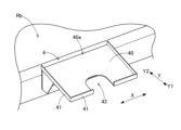
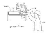
- FIG. 11 is a plan view showing the first-floor running floor of the article transport facility according to the second embodiment; Side view of empty container storage area Perspective view of empty container storage section A diagram showing the work of an operator in an empty container storage section.
- the goods transport equipment includes a transport vehicle that travels along a specified travel route to transport goods, and an goods supply unit that supplies goods to be transported by the transport vehicle.
- a transport vehicle that travels along a specified travel route to transport goods
- an goods supply unit that supplies goods to be transported by the transport vehicle.
- the article transport facility 100 includes multiple travel floors F arranged vertically, and transport vehicles V that travel on travel surfaces Fa formed on each of the multiple travel floors F. On the travel floors F of each level, the multiple transport vehicles V travel on the travel surfaces Fa.
- the item transport equipment 100 has two levels of running floors F.
- FIG. 1 shows a first level running floor F and a second level running floor F.
- the item transport equipment 100 is not limited to this configuration, and may have three or more levels of running floors F.
- the item transport equipment 100 includes a transport passage Fr, which is a passage along which the transport vehicle V travels to transport the item G.
- the transport passage Fr is configured as a part of the travel floor F.
- the travel floor F on each floor includes a transport passage Fr and a travel field Ff.
- the transport passage Fr is a single passage provided across the work area WA and the sorting area SA described below.
- the travel field Ff is a flat portion of the travel floor F.
- the transport vehicle V is capable of traveling freely along the travel field Ff.
- the transport passage Fr and the travel field Ff overlap in part.
- the travel field Ff is provided between the work area WA and the sorting area SA
- the transport passage Fr is provided to cross the travel field Ff between the work area WA and the sorting area SA.
- the direction along the conveying passage Fr is referred to as the "passage direction X”
- the direction perpendicular to the passage direction X when viewed from the top and bottom is referred to as the "passage width direction Y”.
- One side of the passage direction X is referred to as the "passage direction first side X1”
- the other side of the passage direction X is referred to as the "passage direction second side X2”.
- One side of the passage width direction Y is referred to as the “passage width direction first side Y1”
- the other side of the passage width direction Y is referred to as the "passage width direction second side Y2".
- the transport vehicle V is configured to travel straight and also to change direction by rotating on the spot around an up-down axis. By performing straight-line travel and rotating operations, the transport vehicle V is able to travel freely on the travel field Ff on both the first-floor travel floor F and the second-floor travel floor F.
- the item transport equipment 100 includes a pair of lifters L that raise and lower the transport vehicle V across multiple levels (two levels in this example) of running floors F, an item supply section Pg to which items G are supplied, a work area WA in which the items G supplied from the item supply section Pg are handed over to the transport vehicle V, a sorting area SA in which sorting of the items G is performed, and an empty container recovery device B that recovers empty containers C generated by the sorting work in the sorting area SA.
- both the work area WA and the sorting area SA are located at the same level as the travel floor F on the first floor. And, neither the work area WA nor the sorting area SA is located on the travel floor F on the second floor.
- the work area WA is disposed adjacent to both the transport passage Fr and the item supply section Pg.
- the item supply section Pg supplies the items G to the work area WA in a state where they are contained in a supply container Cp.
- the items G contained in the supply container Cp are taken out and the items G are handed over to the transport vehicle V waiting in the transport passage Fr.
- the delivery of the items G to the transport vehicle V may be performed in a state where the items G are contained in a container C other than the supply container Cp, or may be performed in a manner in which the items G are handed over as is without being contained in a container C.
- the above work in the work area WA is performed by a worker W.
- the above work may be performed by a robot instead of the worker W, or may be performed by both the worker W and the robot.
- the transport vehicle V is configured to transport an item G or a container C containing an item G.
- the transport vehicle V transports the item G or a container C containing the item G received in the work area WA to the sorting area SA.
- the sorting area SA is located adjacent to the transport path Fr in the path width direction Y, away from the work area WA.
- sorting work is carried out on the items G transported by the transport vehicles V.
- the sorting work is carried out based on predetermined order information.
- the order information includes various information such as customer information, shipping destination information, and item type information.
- a removal operation is performed in the sorting area SA to remove the item G from the container C transported by the transport vehicle V. That is, the sorting operation includes a removal operation to remove the item G from the container C transported by the transport vehicle V. This removal operation separates the container C from the item G, resulting in an empty container C.
- a receiving operation is performed in the sorting area SA to receive the item G transported by the transport vehicle V.
- the item G removed from the container C by the removal operation and the item G received by the receiving operation are stored, for example, in a container (not shown) according to the shipping destination.
- the empty container recovery device B is configured to recover the empty containers C generated by the above-mentioned removal operation.
- a recovery path Rb which is a path along which the empty containers C are transported by the empty container recovery device B, extends to a position adjacent to the work area WA. In this example, the recovery path Rb extends to the inside of the work area WA.
- the empty containers C recovered by the empty container recovery device B are transported along the recovery path Rb to the work area WA and used for work in the work area WA.
- the empty container recovery device B is configured using, for example, a conveyor.
- the empty container recovery device B configured using a conveyor extends along the recovery path Rb.
- the sorting work (including the above-mentioned removal work) in the sorting area SA is performed by a worker W. However, the sorting work may be performed by a robot instead of the worker W, or the sorting work may be performed by both the worker W and the robot.
- the transport vehicle V delivers the item G to the sorting area SA, it gets on the lifter L and heads to the running floor F on another floor (the second floor running floor F in this example).
- the transport vehicle V then travels along the second floor running floor F and gets on another lifter L, returning to the running floor F on the floor where the above-mentioned work area WA and sorting area SA are located (the first floor running floor F in this example).
- the returning transport vehicle V picks up the item G in the work area WA and transports the item G to the sorting area SA, in the same manner as above.
- the sorting area SA is an area where sorting work of the items G is carried out, and is provided adjacent to the conveying path Fr in the path width direction Y.
- multiple sorting conveyors Sc are arranged in the sorting area SA to transport items G or containers C received from the transport vehicle V.
- Each of the multiple sorting conveyors Sc transports the items G or containers C received from the transport vehicle V to the work location of a worker W (or robot) working in the sorting area SA.
- This allows multiple work locations within the sorting area SA to be distributed and positioned according to the number of sorting conveyors Sc. This makes it easier to perform sorting work at each work location, contributing to improved work efficiency overall.
- each sorting conveyor Sc is lined up along the aisle direction X, and each sorting conveyor Sc is arranged to transport items G or containers C along the aisle width direction Y.
- each sorting conveyor Sc is configured to transport items G or containers C along the aisle width direction Y.
- multiple sorting conveyors Sc are arranged on both sides of the transport path Fr in the sorting area SA. This allows sorting work to be performed on both sides of the transport path Fr, making it possible to improve the sorting work capacity of the sorting area SA as a whole.
- the multiple sorting conveyors Sc arranged on the first side Y1 of the transport path Fr in the path width direction are referred to as a first sorting conveyor group Sc1
- the multiple sorting conveyors Sc arranged on the second side Y2 of the transport path Fr in the path width direction are referred to as a second sorting conveyor group Sc2.
- the empty container recovery device B is configured to recover empty containers C generated by the removal operation performed as part of the sorting operation.
- This removal operation involves removing items G from containers C transported by a transport vehicle V.
- the empty containers C are transported to the work area WA along the recovery path Rb.
- the recovery path Rb extends in a direction intersecting the direction in which the sorting conveyor Sc transports the items G or containers C, as viewed in the vertical direction, and is arranged so as to overlap with the sorting conveyor Sc.
- the recovery path Rb extends in a direction perpendicular to each sorting conveyor Sc, which extends in the aisle width direction Y, as viewed in the vertical direction, that is, along the aisle direction X.
- the recovery path Rb is disposed at a different height from the transport path Fr. More specifically, the collection path Rb is disposed at a position higher than the transport path Fr.
- the height at which the collection path Rb is disposed is preferably at a height near the chest of a worker W of average height. This makes it easy for the worker W to place the empty container C on the collection path Rb.
- a position adjustment mechanism for adjusting the position of the collection path Rb with respect to the worker W may be provided.
- the recovery path Rb includes a first section Rb1 extending along the passage direction X and arranged so as to overlap the first sorting conveyor group Sc1 in an up-down view, a second section Rb2 extending along the passage direction X and arranged so as to overlap the second sorting conveyor group Sc2 in an up-down view, and a connection section Rbc (see FIG. 1) connecting the ends of the first section Rb1 and the second section Rb2 that are furthest from the work area WA.
- the recovery path Rb is composed of a single path arranged so as to overlap the first sorting conveyor group Sc1 and the second sorting conveyor group Sc2 in an up-down view.
- empty containers C generated by sorting operations in each of the first sorting conveyor group Sc1 and the second sorting conveyor group Sc2 arranged separately on both sides of the transport path Fr can be collected by a single recovery path Rb and transported to the work area WA.
- the portion of one of the first section Rb1 and the second section Rb2 (here, the first section Rb1) opposite the side where the connection section Rbc is connected extends to a position adjacent to the work area WA (in this example, further into the work area WA).
- the connection section Rbc is positioned so as to overlap with the transport path Fr when viewed in the up-down direction.
- connection portion between the first section Rb1 and the connection section Rbc, and the connection portion between the second section Rb2 and the connection section Rbc are formed in an arc shape when viewed in the vertical direction. This makes it easier to keep constant the movement speed of the container C transported through the different sections of the collection path Rb, and enables the container C to be transported smoothly.
- the work area WA is an area where the work of transferring the articles G supplied from the article supply section Pg to the transport vehicle V is carried out, and is disposed adjacent to both the transport path Fr and the article supply section Pg. A detailed description will be given below.
- the work area WA is disposed adjacent to the first side Y1 in the aisle width direction of the transport path Fr and adjacent to the first side X1 in the aisle direction of the item supply unit Pg.
- the item G is received from the first side X1 in the aisle direction of the item supply unit Pg, and the item G is handed over from the first side Y1 in the aisle width direction to the transport vehicle V waiting in the transport path Fr.
- the work area WA is positioned adjacent to the exit of the transport vehicle V on the lifter L. This allows the item G to be handed over to the transport vehicle V immediately after it leaves the lifter L, making it easier to avoid a situation where the transport vehicle V traveling within the facility is not transporting an item G.
- a waiting space 3 in which at least one transport vehicle V can wait is provided between the lifter L and the work area WA in the transport passage Fr. This allows at least one transport vehicle V to wait to receive an item G after leaving the lifter L when work in the work area WA is delayed.
- a temporary placement table 1 for temporarily placing items G supplied from the item supply unit Pg is provided in an area sandwiched between the transport path Fr and the item supply unit Pg in the path width direction Y on the second side X2 of the path direction with respect to the work area WA.
- the temporary placement table 1 is provided in an area sandwiched between the above-mentioned waiting space 3 and the item supply unit Pg in the path width direction Y.
- the item G supplied from the item supply unit Pg can be placed on the temporary placement table 1.
- the item supply unit Pg can supply the next item G. Therefore, the supply of items G can be prevented from being delayed without stopping the operation of the item supply unit Pg.
- a container C capable of storing items G is placed on the temporary placement table 1. This allows multiple items G supplied sequentially from the item supply unit Pg to be stored in the container C. Then, when the time comes for the items G to be handed over to the transport vehicle V, the items G contained in the container C can be handed over to the transport vehicle V together with the container C, or the items G can be removed from the container C and handed over to the transport vehicle V.
- the container C for work in the work area WA as shown in FIG. 4(a)
- the items G contained in multiple supply containers Cp and supplied sequentially can be stored in the container C on the temporary placement table 1, and the stored multiple items G can be handed over to the transport vehicle V together with the container C.
- Another advantage of using the container C is that, for example, items G that tend to roll can be stably transported to the transport vehicle V.
- an item G that tends to roll is supplied from the item supply unit Pg, even if there is only one item G, it can be stored in the container C on the temporary placement table 1 and handed over to the transport vehicle V. This makes it possible to prevent the item G from falling off the transport vehicle V during transport by the transport vehicle V.
- the item G is difficult to roll, it may be handed over directly to the transport vehicle V without being stored in the container C, as shown in FIG. 4(b).
- the transport vehicle V is not waiting, it is preferable to store the item G in the container C until it can be handed over to the transport vehicle V.
- the temporary placement table 1 is arranged at a lower position than the item supply position where the item G is supplied by the item supply unit Pg. This makes it easy to store the item G supplied from the item supply unit Pg in the container C on the temporary placement table 1. Furthermore, the temporary placement table 1 is arranged at a higher position than the transport path Fr. This makes it easy to transfer the container C on the temporary placement table 1 to the transport vehicle V on the transport path Fr. That is, the item G can be moved from the item supply unit Pg to the temporary placement table 1 and from the temporary placement table 1 to the transport vehicle V by work in the work area WA.
- the item supply position in the item supply unit Pg, the position of the temporary placement table 1, and the position of the transport vehicle V on the transport path Fr are arranged from top to bottom in the order described. This makes it possible to reduce the workload by simply moving the item G from top to bottom during work in the work area WA.
- the notification unit 2 is provided in the work area WA.
- the notification unit 2 is configured to notify the worker W that an empty container C transported through the recovery route Rb has arrived at the work area WA.
- the notification unit 2 notifies the worker W, for example, by a visual effect or an auditory effect.
- the notification unit 2 is configured, for example, using a lamp, and notifies the worker W by a visual effect.
- the notification unit 2 may be configured using a display device such as a monitor instead of or in addition to a lamp, and may thereby notify the worker W of the arrival of the empty container C.
- the notification unit 2 may be configured, for example, using a buzzer, and may notify the worker W by an auditory effect.
- the notification unit 2 may be configured using a lamp and a buzzer, and may notify the worker W by both a visual effect and an auditory effect.
- an empty container storage section 4 for storing one or more empty containers C to be inserted into the recovery route Rb is disposed adjacent to the recovery route Rb.
- the empty container storage section 4 is configured to be able to store empty containers C generated by removal work in the sorting area SA (the work of removing items G from containers C transported by a transport vehicle V).
- the empty containers C are transported to the work area WA by being inserted into the recovery route Rb of the empty container recovery device B, and the empty container storage section 4 can store empty containers C before being inserted into the recovery route Rb.
- multiple empty container storage sections 4 are provided.
- the multiple empty container storage sections 4 are arranged at intervals from each other along the extension direction of the recovery path Rb (pathway direction X in this example).
- the number of empty container storage sections 4 is less than the number of sorting conveyors Sc.
- each empty container storage section 4 is shared by multiple sorting conveyors Sc.
- the empty container storage section 4 has a container support surface 40 that supports the empty container C from below.
- the empty container storage section 4 is constructed using a plate material, and a part of the plate material is formed as the container support surface 40.
- the container support surface 40 is arranged in an inclined position so that it slopes downward as it moves away from the recovery path Rb.
- the container support surface 40 is inclined so that the end on the recovery path Rb side in the aisle width direction Y is higher than the end on the opposite side to the recovery path Rb in the aisle width direction Y. This makes it easier for a worker W who is located outside the empty container storage section 4 in the aisle width direction Y (first side Y1 in the illustrated example) to place an empty container C on the container support surface 40.
- the empty container storage section 4 is provided with a stopper wall 41 that rises upward from the outer edge of the container support surface 40.
- the stopper wall 41 has the function of restricting the downward movement of the empty containers C supported on the container support surface 40. This prevents the empty containers C supported on the container support surface 40 from falling out of the empty container storage section 4.
- the stopper wall 41 is provided in a configuration in which the container support surface 40 is inclined, as in this embodiment.
- the stopper wall 41 is provided.
- the stopper wall 41 does not need to be provided.
- the recovery path Rb is provided with a conveying surface Fb that supports the transported empty containers C from below.
- the empty container recovery device B is constructed using a conveyor, and the upper surface of the conveyor serves as the conveying surface Fb.
- the height of the adjacent portion 40e of the container support surface 40 adjacent to the conveying surface Fb is equal to or greater than the height of the conveying surface Fb. This means that when an empty container C is inserted into the recovery path Rb, there is no need to lift the empty container C. In other words, the empty container C can be inserted into the recovery path Rb simply by pushing it toward the recovery path Rb. Note that in the illustrated example, the height of the adjacent portion 40e of the container support surface 40 is higher than the conveying surface Fb, but the two may be located at the same height.
- the empty container storage section 4 has a gap 42 formed in a part of the container support surface 40.
- the gap 42 is formed so as to extend from the end of the container support surface 40 opposite the recovery path Rb toward the recovery path Rb.
- the gap 42 is a cutout portion in which the end of the container support surface 40 opposite the recovery path Rb is cut out.
- the gap 42 makes it easy for the worker W to insert the empty container C into the recovery path Rb. That is, as shown in FIG. 8, when the worker W pushes an empty container C stored in the empty container storage section 4 toward the recovery path Rb, the worker W can insert his or her hand into the gap 42 to push the empty container C out. With this configuration, the worker W does not need to reach his or her hand above the container support surface 40 to push out the empty container C. Therefore, the empty container C can be efficiently pushed out toward the recovery path Rb. This configuration is highly beneficial for workers who are relatively short in stature.
- a guide member for guiding the empty container C pushed toward the collection path Rb may be provided between the collection path Rb and the empty container storage section 4.
- a guide member between the adjacent portion 40e and the conveying surface Fb in the vertical direction makes it easier to smoothly move the empty container C from the container support surface 40 to the conveying surface Fb.
- a container C capable of storing an item G is placed on the temporary placement table 1.
- a container C may not be placed on the temporary placement table 1, and the item G supplied from the item supply unit Pg may be placed on the temporary placement table 1 as is.
- the temporary placement table 1 is provided with a stopper for preventing the item G from falling from the temporary placement table 1, and a recess for preventing the item G placed on the temporary placement table 1 from rolling.
- each of the multiple sorting conveyors Sc is arranged to transport items G or containers C along the aisle width direction Y.
- the transport direction of the items G or containers C by the multiple sorting conveyors Sc can be set arbitrarily depending on the operation of the equipment, etc.
- the recovery route Rb is configured as a single route, including a first section Rb1 that overlaps with the first sorting conveyor group Sc1 in a vertical view, a second section Rb2 that overlaps with the second sorting conveyor group Sc2 in a vertical view, and a connecting section Rbc that connects the first section Rb1 and the second section Rb2.
- the recovery route Rb may include multiple separated routes. Even in this case, it is preferable that the multiple separated routes extend to a position adjacent to the work area WA.
- the recovery path Rb extends to a position adjacent to the work area WA.
- the recovery path Rb may extend to, for example, the temporary placement table 1.
- the terminal end of the recovery path Rb in the transport direction may be configured as the temporary placement table 1. In this way, it is not necessary to move the empty container C transported along the recovery path Rb to the temporary placement table 1.
- the recovery path Rb is located at a different height than the transport path Fr.
- the recovery path Rb may be located at the same height as the transport path Fr.
- the gap 42 is a cutout portion formed by cutting out the end of the container support surface 40 on the opposite side to the recovery path Rb.
- the gap 42 may be formed between the pair of plate materials.
- the container support surface 40 may also be configured so that the gap 42 is not provided.
- An article transport facility including a transport vehicle that travels along a specified travel route to transport an article, and an article supply unit that supplies the article to be transported by the transport vehicle, a conveying passageway along which the conveying vehicle travels to convey the article;
- a direction along the conveying passage is defined as a passage direction, a direction perpendicular to the passage direction when viewed in a vertical direction is defined as a passage width direction, one side of the passage direction is defined as a passage direction first side, the other side of the passage direction is defined as a passage direction second side, one side of the passage width direction is defined as the passage width direction first side, and the other side of the passage width direction is defined as the passage width direction second side, a work area disposed adjacent to the conveying passage on a first side in the passage width direction and adjacent to the article supply unit on the first side in the passage direction, in which the article supplied from the article supply unit is handed over to the conveying vehicle;
- a temporary placement table for temporarily placing the items supplied from the item supply section is provided in an area on the
- the item supply unit, the temporary placement table, and the transport passage are arranged in line in the passage width direction, so that items can be moved smoothly from the item supply unit to the temporary placement table, and from the temporary placement table to the transport vehicle in the transport passage.
- a container capable of accommodating the item is disposed on the temporary placement table,
- the transport vehicle is preferably configured to transport the item or the container containing the item.
- a sorting area in which the sorting operation of the article is performed is provided adjacent to the conveying passage in the passage width direction at a location separated from the work area,
- the transport vehicle transports the item or the container containing the item received in the work area to the sorting area,
- the sorting operation includes a removal operation of removing the items from the container transported by the transport vehicle;
- an empty container recovery device is provided for recovering the empty containers generated by the removal operation; It is preferable that a recovery path along which the empty containers are transported by the empty container recovery device extends to a position adjacent to the work area.
- the containers can be collected by the empty container collection device after the items have been removed and emptied.
- the collected empty containers can then be transported along the collection path to the work area, making them available for reuse in work in the work area.
- An empty container storage unit for storing one or more empty containers to be inserted into the recovery path is disposed adjacent to the recovery path,
- the empty container storage section includes a container support surface that supports the empty container from below,
- the recovery path includes a conveying surface that supports the empty container being conveyed from below, It is preferable that a height of an adjacent portion of the container support surface adjacent to the transport surface is equal to or greater than a height of the transport surface.
- containers that have been emptied after items have been removed can be temporarily stored in the empty container storage section before being loaded into the collection path. Therefore, empty containers from which items have been removed can be loaded into the collection path at a convenient time.
- multiple empty containers can be stored in the empty container storage section, multiple empty containers can be loaded into the collection path at one time, making it easier to reduce labor hours.
- the height of the adjacent portion of the container support surface that is adjacent to the conveying surface is equal to or greater than the height of the conveying surface, there is no need to lift the empty container when loading it into the collection path, and the loading operation can be performed easily.
- An empty container storage unit for storing one or more empty containers to be inserted into the recovery path is disposed adjacent to the recovery path,
- the empty container storage section includes a container support surface that supports the empty container from below, A plurality of the empty container storage sections are provided, It is preferable that the empty container storage sections are arranged at intervals from each other along the extension direction of the recovery path.
- empty containers can be stored at multiple locations along the extension direction of the collection path.
- a plurality of sorting conveyors for transporting the items or containers received from the transport vehicles are disposed in the sorting area;
- a plurality of the sorting conveyors are arranged along the passage direction, and each of the sorting conveyors is arranged to transport the article or the container along the passage width direction, It is preferable that the recovery path extends in a direction intersecting a direction in which the sorting conveyor transports the articles or containers and is arranged so as to overlap with the sorting conveyor when viewed in the vertical direction.
- a plurality of the sorting conveyors are disposed on both sides of the conveying passage in the sorting area, A plurality of the sorting conveyors arranged on a first side in the passage width direction with respect to the conveying passage are defined as a first sorting conveyor group, and a plurality of the sorting conveyors arranged on a second side in the passage width direction with respect to the conveying passage are defined as a second sorting conveyor group,
- the recovery path comprises a first section extending along the aisle direction and arranged so as to overlap with the first sorting conveyor group when viewed in the vertical direction, a second section extending along the aisle direction and arranged so as to overlap with the second sorting conveyor group when viewed in the vertical direction, and a connecting section connecting the ends of the first section and the second section that are furthest from the working area.
- empty containers generated by sorting operations on the first and second sorting conveyor groups which are arranged on either side of the transport path, can be collected and transported to the work area via a single collection path.
- the recovery path is located at a different height than the transport passage.
- This configuration makes it easy to set the extension direction of the collection path and the transport path with a high degree of freedom.
- a notification unit is provided in the work area, The notification unit is preferably configured to notify that the empty container transported along the collection path has reached the work area.
- the technology disclosed herein can be used in an item transport facility that includes a transport vehicle that travels along a specified travel path to transport items, and an item supply unit that supplies the items to be transported by the transport vehicle.
Landscapes
- Engineering & Computer Science (AREA)
- Mechanical Engineering (AREA)
- Warehouses Or Storage Devices (AREA)
Priority Applications (3)
| Application Number | Priority Date | Filing Date | Title |
|---|---|---|---|
| JP2025502286A JP7816630B2 (ja) | 2023-02-21 | 2024-02-13 | 物品搬送設備(article transport facility) |
| CN202480013560.2A CN120813532A (zh) | 2023-02-21 | 2024-02-13 | 物品输送设备 |
| EP24760187.5A EP4640589A1 (en) | 2023-02-21 | 2024-02-13 | Article transport facility |
Applications Claiming Priority (2)
| Application Number | Priority Date | Filing Date | Title |
|---|---|---|---|
| JP2023025250 | 2023-02-21 | ||
| JP2023-025250 | 2023-02-21 |
Publications (1)
| Publication Number | Publication Date |
|---|---|
| WO2024176885A1 true WO2024176885A1 (ja) | 2024-08-29 |
Family
ID=92500810
Family Applications (1)
| Application Number | Title | Priority Date | Filing Date |
|---|---|---|---|
| PCT/JP2024/004711 Ceased WO2024176885A1 (ja) | 2023-02-21 | 2024-02-13 | 物品搬送設備(article transport facility) |
Country Status (5)
| Country | Link |
|---|---|
| EP (1) | EP4640589A1 (https=) |
| JP (1) | JP7816630B2 (https=) |
| CN (1) | CN120813532A (https=) |
| TW (1) | TW202448769A (https=) |
| WO (1) | WO2024176885A1 (https=) |
Citations (5)
| Publication number | Priority date | Publication date | Assignee | Title |
|---|---|---|---|---|
| JPH04350019A (ja) | 1991-02-12 | 1992-12-04 | Murata Mach Ltd | 物品仕分け搬出装置 |
| JP2012131644A (ja) * | 2012-04-06 | 2012-07-12 | Daifuku Co Ltd | 仕分け設備 |
| JP2022016577A (ja) * | 2018-07-13 | 2022-01-21 | 株式会社ダイフク | 物品仕分け設備 |
| WO2022153659A1 (ja) * | 2021-01-12 | 2022-07-21 | 村田機械株式会社 | ピッキングシステム及びピッキングシステムの制御方法 |
| JP2023023631A (ja) * | 2021-08-05 | 2023-02-16 | 株式会社ダイフク | 物品収容設備、物品収容方法、及び物品収容プログラム |
-
2024
- 2024-02-13 CN CN202480013560.2A patent/CN120813532A/zh active Pending
- 2024-02-13 JP JP2025502286A patent/JP7816630B2/ja active Active
- 2024-02-13 WO PCT/JP2024/004711 patent/WO2024176885A1/ja not_active Ceased
- 2024-02-13 EP EP24760187.5A patent/EP4640589A1/en active Pending
- 2024-02-19 TW TW113105807A patent/TW202448769A/zh unknown
Patent Citations (5)
| Publication number | Priority date | Publication date | Assignee | Title |
|---|---|---|---|---|
| JPH04350019A (ja) | 1991-02-12 | 1992-12-04 | Murata Mach Ltd | 物品仕分け搬出装置 |
| JP2012131644A (ja) * | 2012-04-06 | 2012-07-12 | Daifuku Co Ltd | 仕分け設備 |
| JP2022016577A (ja) * | 2018-07-13 | 2022-01-21 | 株式会社ダイフク | 物品仕分け設備 |
| WO2022153659A1 (ja) * | 2021-01-12 | 2022-07-21 | 村田機械株式会社 | ピッキングシステム及びピッキングシステムの制御方法 |
| JP2023023631A (ja) * | 2021-08-05 | 2023-02-16 | 株式会社ダイフク | 物品収容設備、物品収容方法、及び物品収容プログラム |
Non-Patent Citations (1)
| Title |
|---|
| See also references of EP4640589A1 |
Also Published As
| Publication number | Publication date |
|---|---|
| JPWO2024176885A1 (https=) | 2024-08-29 |
| TW202448769A (zh) | 2024-12-16 |
| EP4640589A1 (en) | 2025-10-29 |
| JP7816630B2 (ja) | 2026-02-18 |
| CN120813532A (zh) | 2025-10-17 |
Similar Documents
| Publication | Publication Date | Title |
|---|---|---|
| EP3606846B1 (en) | Method and system for transporting units within a storage facility | |
| CN103889864B (zh) | 用于从仓库提供运输单元的方法 | |
| CN105473469B (zh) | 通过在分拣站处准备储藏单元的订单履行方法 | |
| US20150378345A1 (en) | Automated order-picking station for the manual picking of articles from storage containers into an order container | |
| US20220219899A1 (en) | High-density automated storage and retrieval system | |
| US20100036521A1 (en) | Automated order-picking system having an integrated sorting function and method for operating the system | |
| JP5930406B2 (ja) | ピッキング設備 | |
| EP4245693B1 (en) | Article storage facility | |
| JP6231168B2 (ja) | 立体自動倉庫 | |
| US20240262626A1 (en) | System and method for picking flatpack articles | |
| KR20230117526A (ko) | 물품 분류 설비 | |
| KR20230008203A (ko) | 제품 저장고 및 적어도 하나의 주문 이행 영역을 갖는 주문 이행을 위한 창고 | |
| JP2019172448A (ja) | 物流システム | |
| JP2018188244A (ja) | 有軌道搬送車システム | |
| JP7314924B2 (ja) | 物品収容設備 | |
| JP7225488B2 (ja) | 目的地指定物品トレイ載置搬送システム | |
| CN120548289A (zh) | 物品输送设备 | |
| JP7816630B2 (ja) | 物品搬送設備(article transport facility) | |
| TW202233499A (zh) | 撿選系統及撿選系統之控制方法 | |
| WO2024095889A1 (ja) | 物品搬送設備(article transport facility) | |
| JP6848676B2 (ja) | ピッキングシステム | |
| JP2019127347A (ja) | ケース移載システム及びケース移載方法 | |
| CN116568615A (zh) | 物品保管设备 | |
| JP2017081754A (ja) | 立体自動倉庫 | |
| JP2709205B2 (ja) | 物品の取り扱い方法 |
Legal Events
| Date | Code | Title | Description |
|---|---|---|---|
| 121 | Ep: the epo has been informed by wipo that ep was designated in this application |
Ref document number: 24760187 Country of ref document: EP Kind code of ref document: A1 |
|
| WWE | Wipo information: entry into national phase |
Ref document number: 2025502286 Country of ref document: JP |
|
| WWE | Wipo information: entry into national phase |
Ref document number: 2024760187 Country of ref document: EP |
|
| ENP | Entry into the national phase |
Ref document number: 2024760187 Country of ref document: EP Effective date: 20250725 |
|
| ENP | Entry into the national phase |
Ref document number: 2024760187 Country of ref document: EP Effective date: 20250725 |
|
| WWE | Wipo information: entry into national phase |
Ref document number: 202480013560.2 Country of ref document: CN |
|
| NENP | Non-entry into the national phase |
Ref country code: DE |
|
| WWP | Wipo information: published in national office |
Ref document number: 202480013560.2 Country of ref document: CN |
|
| WWP | Wipo information: published in national office |
Ref document number: 2024760187 Country of ref document: EP |