WO2024176647A1 - 管継手用チューブ着脱部材、管継手および管継手組立方法 - Google Patents
管継手用チューブ着脱部材、管継手および管継手組立方法 Download PDFInfo
- Publication number
- WO2024176647A1 WO2024176647A1 PCT/JP2024/000770 JP2024000770W WO2024176647A1 WO 2024176647 A1 WO2024176647 A1 WO 2024176647A1 JP 2024000770 W JP2024000770 W JP 2024000770W WO 2024176647 A1 WO2024176647 A1 WO 2024176647A1
- Authority
- WO
- WIPO (PCT)
- Prior art keywords
- tube
- ring
- cap
- lock ring
- release
- Prior art date
- Legal status (The legal status is an assumption and is not a legal conclusion. Google has not performed a legal analysis and makes no representation as to the accuracy of the status listed.)
- Ceased
Links
Images


Classifications
-
- F—MECHANICAL ENGINEERING; LIGHTING; HEATING; WEAPONS; BLASTING
- F16—ENGINEERING ELEMENTS AND UNITS; GENERAL MEASURES FOR PRODUCING AND MAINTAINING EFFECTIVE FUNCTIONING OF MACHINES OR INSTALLATIONS; THERMAL INSULATION IN GENERAL
- F16L—PIPES; JOINTS OR FITTINGS FOR PIPES; SUPPORTS FOR PIPES, CABLES OR PROTECTIVE TUBING; MEANS FOR THERMAL INSULATION IN GENERAL
- F16L37/00—Couplings of the quick-acting type
- F16L37/08—Couplings of the quick-acting type in which the connection between abutting or axially overlapping ends is maintained by locking members
- F16L37/084—Couplings of the quick-acting type in which the connection between abutting or axially overlapping ends is maintained by locking members combined with automatic locking
- F16L37/091—Couplings of the quick-acting type in which the connection between abutting or axially overlapping ends is maintained by locking members combined with automatic locking by means of a ring provided with teeth or fingers
- F16L37/0915—Couplings of the quick-acting type in which the connection between abutting or axially overlapping ends is maintained by locking members combined with automatic locking by means of a ring provided with teeth or fingers with a separate member for releasing the coupling
-
- F—MECHANICAL ENGINEERING; LIGHTING; HEATING; WEAPONS; BLASTING
- F16—ENGINEERING ELEMENTS AND UNITS; GENERAL MEASURES FOR PRODUCING AND MAINTAINING EFFECTIVE FUNCTIONING OF MACHINES OR INSTALLATIONS; THERMAL INSULATION IN GENERAL
- F16L—PIPES; JOINTS OR FITTINGS FOR PIPES; SUPPORTS FOR PIPES, CABLES OR PROTECTIVE TUBING; MEANS FOR THERMAL INSULATION IN GENERAL
- F16L37/00—Couplings of the quick-acting type
- F16L37/08—Couplings of the quick-acting type in which the connection between abutting or axially overlapping ends is maintained by locking members
- F16L37/084—Couplings of the quick-acting type in which the connection between abutting or axially overlapping ends is maintained by locking members combined with automatic locking
-
- F—MECHANICAL ENGINEERING; LIGHTING; HEATING; WEAPONS; BLASTING
- F16—ENGINEERING ELEMENTS AND UNITS; GENERAL MEASURES FOR PRODUCING AND MAINTAINING EFFECTIVE FUNCTIONING OF MACHINES OR INSTALLATIONS; THERMAL INSULATION IN GENERAL
- F16L—PIPES; JOINTS OR FITTINGS FOR PIPES; SUPPORTS FOR PIPES, CABLES OR PROTECTIVE TUBING; MEANS FOR THERMAL INSULATION IN GENERAL
- F16L21/00—Joints with sleeve or socket
- F16L21/02—Joints with sleeve or socket with elastic sealing rings between pipe and sleeve or between pipe and socket, e.g. with rolling or other prefabricated profiled rings
-
- F—MECHANICAL ENGINEERING; LIGHTING; HEATING; WEAPONS; BLASTING
- F16—ENGINEERING ELEMENTS AND UNITS; GENERAL MEASURES FOR PRODUCING AND MAINTAINING EFFECTIVE FUNCTIONING OF MACHINES OR INSTALLATIONS; THERMAL INSULATION IN GENERAL
- F16L—PIPES; JOINTS OR FITTINGS FOR PIPES; SUPPORTS FOR PIPES, CABLES OR PROTECTIVE TUBING; MEANS FOR THERMAL INSULATION IN GENERAL
- F16L37/00—Couplings of the quick-acting type
- F16L37/08—Couplings of the quick-acting type in which the connection between abutting or axially overlapping ends is maintained by locking members
- F16L37/084—Couplings of the quick-acting type in which the connection between abutting or axially overlapping ends is maintained by locking members combined with automatic locking
- F16L37/091—Couplings of the quick-acting type in which the connection between abutting or axially overlapping ends is maintained by locking members combined with automatic locking by means of a ring provided with teeth or fingers
-
- F—MECHANICAL ENGINEERING; LIGHTING; HEATING; WEAPONS; BLASTING
- F16—ENGINEERING ELEMENTS AND UNITS; GENERAL MEASURES FOR PRODUCING AND MAINTAINING EFFECTIVE FUNCTIONING OF MACHINES OR INSTALLATIONS; THERMAL INSULATION IN GENERAL
- F16L—PIPES; JOINTS OR FITTINGS FOR PIPES; SUPPORTS FOR PIPES, CABLES OR PROTECTIVE TUBING; MEANS FOR THERMAL INSULATION IN GENERAL
- F16L37/00—Couplings of the quick-acting type
- F16L37/08—Couplings of the quick-acting type in which the connection between abutting or axially overlapping ends is maintained by locking members
- F16L37/084—Couplings of the quick-acting type in which the connection between abutting or axially overlapping ends is maintained by locking members combined with automatic locking
- F16L37/092—Couplings of the quick-acting type in which the connection between abutting or axially overlapping ends is maintained by locking members combined with automatic locking by means of elements wedged between the pipe and the frusto-conical surface of the body of the connector
-
- F—MECHANICAL ENGINEERING; LIGHTING; HEATING; WEAPONS; BLASTING
- F16—ENGINEERING ELEMENTS AND UNITS; GENERAL MEASURES FOR PRODUCING AND MAINTAINING EFFECTIVE FUNCTIONING OF MACHINES OR INSTALLATIONS; THERMAL INSULATION IN GENERAL
- F16L—PIPES; JOINTS OR FITTINGS FOR PIPES; SUPPORTS FOR PIPES, CABLES OR PROTECTIVE TUBING; MEANS FOR THERMAL INSULATION IN GENERAL
- F16L43/00—Bends; Siphons
- F16L43/02—Bends; Siphons adapted to make use of special securing means
Definitions
- the present invention relates to a tube attachment/detachment member for a pipe joint, a pipe joint, and a method for assembling a pipe joint.
- Patent Document 1 discloses a pipe fitting that uses a lock ring to prevent the tube from coming loose.
- the pipe fitting disclosed in Patent Document 1 includes a release ring whose tip is in contact with or close to the lock ring, and a cylindrical cap fitted onto the release ring.
- the lock ring has claws to prevent the tube from coming off.
- the release ring is mounted on the cap so that it can move forward and backward relative to the lock ring.
- the cap is press-fitted into the connection hole of the valve housing, fixing the lock ring within the connection hole and preventing the release ring from coming off.
- the housing corresponds to the body of the pipe fitting.
- the present invention aims to simplify the assembly process of pipe fittings equipped with tube attachment/detachment members.
- the present invention relates to a tube attachment/detachment member for connecting a tube to a body, and comprises a lock ring that is formed so that the tube can be inserted and that holds the inserted tube, a release ring that releases the lock ring from holding the tube, a cap that houses the lock ring and the release ring, and a buckling ring that limits the movement of the lock ring and the release ring, the buckling ring being provided within the cap, and the cap being formed so that the outer periphery of the body can be fitted into it.
- the present invention also relates to a pipe joint installation method for attaching a tube attachment member for connecting a tube to a body to the body, the tube attachment member having a lock ring that is formed so that the tube can be inserted and that holds the inserted tube, a release ring that releases the lock ring from holding the tube, a cap that houses the lock ring and the release ring, and a buckle ring that is provided within the cap and limits the movement of the lock ring and the release ring, and the pipe joint installation method includes fitting the outer periphery of the body into the cap of the tube attachment member that has been preassembled.
- a tube attachment/detachment member is constructed by attaching a release ring and a lock ring to the cap and using a buckling ring to prevent the release ring and lock ring from falling off the cap.
- the cap is constructed so that the outer periphery of the body can be fitted into it, and a pipe joint is formed by fitting the cap of the tube attachment/detachment member into the body to which a sealing material has been attached.
- the tube attachment/detachment member is the same regardless of the shape of the pipe joint, so it is easy to automatically assemble just the tube attachment/detachment member.
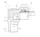
- FIG. 4 is a vertical cross-sectional view cut in half of the tube attachment/detachment member according to the embodiment, showing a state in which the tube and the body are connected.
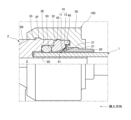
- FIG. FIG. 2 is an enlarged detailed view of part A in FIG.
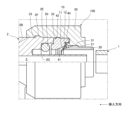
- FIG. 3 is an enlarged detailed view showing a state before the tube is inserted into the lock ring, and corresponds to FIG. 2 .
- 3 is an enlarged detailed view showing a state in which the tube is released from the lock ring, and corresponds to FIG. 2 .
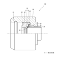
- FIG. 4 is a vertical cross-sectional view cut in half of the tube attachment/detachment member before it is attached to the body.
- FIG. 1 shows a half-cut vertical cross-sectional view of a tube attachment/detachment member 100 according to an embodiment of the present invention.
- FIG. 1 shows a tube 1 and a body 2 connected using the tube attachment/detachment member 100 to form a pipe connection structure.
- the tube attachment/detachment member 100, the body 2, and a sealing member 50 described below form a pipe joint 1000.
- the body 2 is an L-shaped joint that is connected to an adapter or device (not shown), but these are examples of the body 2 and are not limiting.
- Polyurethane resin, nylon resin, polyethylene resin, etc. can be used as materials for constructing the tube 1.
- Materials for constructing the body 2 can be polyamide 12 (PA12) reinforced with glass fiber (GF), polyamide 11 (PA11) reinforced with GF, PPA reinforced with GF, copper alloy (C3771, etc.), lead-free copper alloy, aluminum alloy, stainless steel alloy, etc.
- the tube 1 and the body 2 connected to each other using the tube attachment/detachment member 100 can be used, for example, in the air brake piping of automobiles, including commercial vehicles (trucks, buses, etc.).
- the pipe connection structure may also be used in construction machinery, machine tools, etc.
- the fluid flowing through the tube 1 and the body 2 is not limited to air, but may be other gases or liquids.
- the body 2 is a cylindrical member bent into an L-shape.
- the body 2 has a vertical section 2A that extends vertically, and a horizontal section 2B that is bent at a substantially right angle from the upper end of the vertical section 2A and extends horizontally as one body.
- a flow path 3 that is bent into an L-shape is formed by large and small circular holes 3a, 3b of different diameters.
- the body 2 is a member that is bent into an L-shape, but the body 2 may be a member of various shapes that are not limited to an L-shape, such as an F-shape, T-shape, or Y-shape, or may be a union shape.
- a flange portion 2C is integrally formed at the mid-height position of the outer periphery of the vertical portion 2A of the body 2.
- the portion below the flange portion 2C forms the insertion portion 2A1 that is inserted into the inside of an adapter (not shown).
- the tube attachment/detachment member 100 is attached to the open end of the horizontal section 2B of the body 2.
- the tube 1 is held by the tube attachment/detachment member 100.
- the tube 1 and the body 2 are connected by the tube attachment/detachment member 100.
- FIG. 2 is an enlarged detailed view of part A shown in FIG. 1.
- the horizontal part 2B of the body 2 has an inner cylindrical part 2D and an outer cylindrical part 2E arranged to surround the inner cylindrical part 2D.
- the inner cylindrical part 2D extends from the outer cylindrical part 2E.
- the inner cylindrical part 2D and the outer cylindrical part 2E form the open end of the horizontal part 2B.
- the inner cylindrical part 2D is inserted into the tube 1.
- the tube attachment/detachment member 100 comprises a lock ring 10 that holds the tube 1, a release ring 20 that is arranged next to the lock ring 10, and a cap 30 that houses the lock ring 10 and the release ring 20.
- the lock ring 10 is made of, for example, metal.
- the release ring 20 and the cap 30 are made of, for example, resin.
- Figure 3 is a plan view of the lock ring 10. As shown in Figure 3, the lock ring 10 has a plurality of claws 11 arranged in an annular shape and a connecting portion 12 that connects adjacent claws 11 in the circumferential direction.
- circumferential direction refers to the direction around the central axis of the lock ring 10.
- radial direction refers to the direction emanating from the central axis of the lock ring 10.
- the connecting portion 12 is positioned radially outward from the claws 11.
- the lock ring 10 is a zigzag-shaped annular member in which the claws 11 are positioned relatively radially inward and the connecting portion 12 is positioned radially outward.
- the tube 1 is inserted into the lock ring 10.
- the insertion direction of the tube 1 is from right to left on the page in FIG. 2.
- the insertion direction of the tube 1 will also be simply referred to as the "insertion direction.”
- the claws 11 of the lock ring 10 are inclined with respect to the insertion direction so that they are inwardly directed radially toward the insertion direction.
- Figure 4 is an enlarged detailed view showing the state before the tube 1 is inserted into the lock ring 10, and corresponds to Figure 2.
- Figure 4 when the tube 1 is not inserted into the lock ring 10, the distance between the claws 11 facing each other in the radial direction is smaller than the outer diameter of the tube 1.
- the claws 11 of the lock ring 10 are pushed in the insertion direction by the tube 1, and are deformed so that the distance between the claws 11 facing each other in the radial direction increases (see Figure 2).
- FIG. 5 is an enlarged detailed view showing the state in which the hold of the tube 1 by the lock ring 10 has been released, and corresponds to Figure 2.
- the release ring 20 is aligned with the lock ring 10 in the insertion direction.
- the central axis of the release ring 20 and the central axis of the lock ring 10 are approximately aligned, and the tube 1 is inserted into the release ring 20.
- the release ring 20 extends from the cap 30 in the opposite direction to the insertion direction, allowing the user to operate the release ring 20.
- the release ring 20 moves in the insertion direction.
- movement in the insertion direction is also referred to as "forward”
- movement in the opposite direction to the insertion direction is also referred to as “reverse.”
- the release ring 20 is housed in the cap 30 so that it can move forward and backward relative to the lock ring 10.
- the release ring 20 When the release ring 20 is moved forward by the user's operation, the release ring 20 pushes the claws 11 of the lock ring 10 in the insertion direction as shown in FIG. 5. This causes the gap between the radially opposing claws 11 to widen, and the claws 11 move away from the tube 1. In this state, even if the tube 1 is pulled in the opposite direction to the insertion direction, the claws 11 of the lock ring 10 do not bite into the tube 1. Therefore, it becomes possible to remove the tube 1 from the lock ring 10.
- the release ring 20 releases the lock ring 10 from its hold on the tube 1 by deforming the lock ring 10 and separating it from the tube 1.
- the cap 30 has a reverse movement limiting portion 31 that limits the reverse movement of the release ring 20.
- the reverse movement limiting portion 31 is a step that protrudes radially inward.
- the release ring 20 has a step 21 that protrudes radially outward, and the reverse movement limiting portion 31 faces the step 21 in the insertion direction.
- the reverse movement limiting portion 31 and the step 21 are in contact with each other, the release ring 20 does not move backward. Therefore, it is possible to prevent the release ring 20 from falling out of the cap 30 in the direction opposite to the insertion direction.
- Figure 6 is a half-cut longitudinal section of the tube attachment/detachment member 100 before it is attached to the body 2.
- the tube attachment/detachment member 100 is equipped with a buckling ring 40 that limits the movement of the lock ring 10 and the release ring 20 in the insertion direction.
- the buckling ring 40 is made of, for example, resin.
- the lock ring 10 is attached inside the buckling ring 40.
- the buckling ring 40 is formed with a step that comes into contact with the connecting portion 12 of the lock ring 10, and the step limits the displacement of the connecting portion 12 of the lock ring 10 in the insertion direction.
- the buckling ring 40 has an inclined surface 41 that is inclined with respect to the insertion direction.
- the inclined surface 41 is inclined toward the insertion direction as it moves radially inward, similar to the claws 11 of the locking ring 10.
- the inclined surface 41 comes into contact with the claws 11 of the locking ring 10, limiting the deformation of the locking ring 10 by the release ring 20. This makes it possible to prevent excessive deformation of the locking ring 10. This makes it possible to prevent the locking ring 10 from being damaged and being unable to hold the tube 1.
- the buckling ring 40 is also sized to function as a backup ring for the sealing member 50, and has a stepped shape that fixes the sealing member 50.
- the buckling ring 40 is provided inside the cap 30.
- the central axis of the buckling ring 40 and the central axis of the locking ring 10 are approximately aligned, and when the tube 1 is inserted into the locking ring 10 (see FIG. 2), the tube 1 is inserted into the buckling ring 40.
- the buckling ring 40 is fitted into the cap 30.
- a protrusion 42 that protrudes radially outward is formed on the outer periphery of the buckling ring 40, and a first recessed portion 32 in which the protrusion 42 can be positioned is formed on the inner periphery of the cap 30.
- the protrusion 42 and the first recessed portion 32 are formed, for example, in an annular shape along the circumferential direction.
- the fitting of the buckling ring 40 into the cap 30 is not limited to the form of the protrusion 42 and the first recessed portion 32.
- a recessed portion may be formed on the outer periphery of the buckling ring 40
- a protrusion may be formed on the inner periphery of the cap 30, and the protrusion may be disposed in the recessed portion to hold the buckling ring 40 in the cap 30.
- a male thread may be formed on the outer periphery of the buckling ring 40, and a female thread may be formed on the inner periphery of the cap 30, and the buckling ring 40 may be held in the cap 30 by screwing the male thread and the female thread.
- the outer shape of the buckling ring 40 may be made larger than the inner shape of the cap 30, and the buckling ring 40 may be held in the cap 30 by pushing the cap 30 apart as the buckling ring 40 is inserted into the cap 30.
- the buckling ring 40 may also be made of metal, the protrusion 42 may be formed into an edge shape, and pressed into the cap 30 in which the first recessed portion 32 is not formed.
- a second recessed portion 33 separate from the first recessed portion 32 is formed on the inner circumference of the cap 30.
- the second recessed portion 33 is located on the insertion direction side of the buckling ring 40 (the left side of the paper in FIG. 6).
- the outer tubular portion 2E of the body 2 is inserted into the cap 30.
- the protrusion 2F formed on the outer periphery of the outer tubular portion 2E is positioned in the second recessed portion 33 of the cap 30, and the cap 30 is held in the body 2.
- the cap 30 is formed so that the outer periphery of the body 2 can be fitted into it.
- the fitting of the body 2 into the cap 30 is not limited to the form of the protrusion 2F and the second recess 33.
- a protrusion may be formed on the inner circumference of the cap 30 and a recess may be formed on the outer circumference of the body 2, and the protrusion may be disposed in the recess to hold the cap 30 to the body 2.
- a female thread may be formed on the inner circumference of the cap 30 and a male thread may be formed on the outer circumference of the body 2, and the cap 30 may be held to the body 2 by screwing the female thread into the male thread.
- the inner shape of the cap 30 may be made smaller than the outer shape of the body 2 when the body 2 is not inserted into the cap 30, and the cap 30 may be held to the body 2 by being pushed open by the body 2 as the body 2 is inserted into the cap 30.
- the buckling ring 40 provided in the cap 30 limits the movement of the lock ring 10 and release ring 20 housed in the cap 30, and the cap 30 is formed so that the outer periphery of the body 2 can be fitted into it.
- the same members can be used for the tube attachment/detachment member 100 as long as the corresponding tube outer diameter dimensions are the same for the body. Therefore, the tube attachment/detachment member 100 can be assembled and stored, and then assembled in a separate process according to the shape of the body 2 to complete the pipe fitting 1000. Furthermore, the assembly of the tube attachment/detachment member 100 can easily be automated by machine.
- a seal member 50 is provided between the outer periphery of the tube 1 and the inner periphery of the outer tubular portion 2E of the body 2.
- the seal member 50 is made of an elastic material such as rubber. The seal member 50 contacts the outer periphery of the tube 1 and the inner periphery of the outer tubular portion 2E of the body 2 to seal the gap between the tube 1 and the body 2 and ensure airtightness. This makes it possible to prevent fluid from leaking between the tube 1 and the body 2.
- the seal member 50 is housed in a step formed in the outer cylindrical portion 2E of the body 2.
- the buckling 40 is adjacent to the outer cylindrical portion 2E in the insertion direction, and prevents the seal member 50 from slipping out of the outer cylindrical portion 2E.
- the release ring 20 is attached to the cap 30 in the direction opposite to the insertion direction.
- the lock ring 10 is attached to the buckling ring 40.
- the buckling ring 40 is then press-fitted into the cap 30.
- the protrusion 42 of the buckling ring 40 is positioned in the first recess 32 of the cap 30, the buckling ring 40 is held in the cap 30, and assembly of the tube attachment/detachment member 100 is completed.
- the reverse movement limiting portion 31 of the cap 30 prevents the lock ring 10 and release ring 20 from falling out in the direction opposite to the insertion direction, and the buckling ring 40 prevents the lock ring 10 and release ring 20 from falling out in the insertion direction.
- the tube 1 is inserted into the tube attachment/detachment member 100 as shown in FIG. 2.
- the tube 1 is held by the lock ring 10.
- the release ring 20 may be pushed in the insertion direction to widen the gap between the claws 11 of the lock ring 10.
- the body 2 has an inner cylindrical portion 2D, but it does not have to have an inner cylindrical portion 2D.
- the buckling ring 40 limits the movement of the lock ring 10 and the release ring 20, and also limits the deformation of the lock ring 10 caused by the release ring 20.
- the buckling ring 40 may only limit the movement of the lock ring 10 and the release ring 20. In this case, it is preferable to provide a member separate from the buckling ring 40 that limits the deformation of the lock ring 10 caused by the release ring 20.
- Tube attachment/detachment member 1000 Pipe joint 1 Tube 2 Body 10 Lock ring 20 Release ring 30 Cap 40 Buckling 50 Sealing member
Landscapes
- Engineering & Computer Science (AREA)
- General Engineering & Computer Science (AREA)
- Mechanical Engineering (AREA)
- Quick-Acting Or Multi-Walled Pipe Joints (AREA)
- Joints With Sleeves (AREA)
Abstract
Description
1000 管継手
1 チューブ
2 ボディ
10 ロックリング
20 リリースリング
30 キャップ
40 バックリング
50 シール部材
Claims (5)
- チューブとボディとを連結するためのチューブ着脱部材であって、
前記チューブが挿入可能に形成され、挿入された前記チューブを保持するロックリングと、
前記ロックリングによる前記チューブの保持を解放するリリースリングと、
前記ロックリングおよび前記リリースリングを収容するキャップと、
前記ロックリングおよび前記リリースリングの移動を制限するバックリングと、を備え、
前記バックリングは、前記キャップ内に設けられており、
前記キャップは、前記ボディの外周が嵌め込み可能に形成されている、
チューブ着脱部材。 - 前記ロックリングは、前記チューブに当接して前記チューブを保持し、
前記リリースリングは、前記ロックリングを変形させて前記チューブから前記ロックリングを離して、前記ロックリングによる前記チューブの保持を解放し、
前記バックリングは、前記リリースリングによる前記ロックリングの変形を制限する、
請求項1に記載のチューブ着脱部材。 - 前記バックリングは、前記キャップに嵌め込まれている、
請求項1に記載のチューブ着脱部材。 - 請求項1に記載のチューブ着脱部材と、
前記キャップに嵌め込まれたボディと、
前記ボディに設けられ、前記チューブと前記ボディとの間を閉塞するシール部材と、を備える、
管継手。 - チューブとボディとを連結するためのチューブ着脱部材を前記ボディに取付ける管継手組立方法であって、
前記チューブ着脱部材は、前記チューブが挿入可能に形成され挿入された前記チューブを保持するロックリングと、前記ロックリングによる前記チューブの保持を解放するリリースリングと、前記ロックリングおよび前記リリースリングを収容するキャップと、前記キャップ内に設けられ前記ロックリングおよび前記リリースリングの移動を制限するバックリングと、を備え、
予め組立てられた前記チューブ着脱部材の前記キャップに前記ボディの外周を嵌め込む、
管継手組立方法。
Applications Claiming Priority (2)
| Application Number | Priority Date | Filing Date | Title |
|---|---|---|---|
| JP2023026591A JP2024119585A (ja) | 2023-02-22 | 2023-02-22 | 管継手用チューブ着脱部材、管継手および管継手組立方法 |
| JP2023-026591 | 2023-02-22 |
Publications (1)
| Publication Number | Publication Date |
|---|---|
| WO2024176647A1 true WO2024176647A1 (ja) | 2024-08-29 |
Family
ID=92379683
Family Applications (1)
| Application Number | Title | Priority Date | Filing Date |
|---|---|---|---|
| PCT/JP2024/000770 Ceased WO2024176647A1 (ja) | 2023-02-22 | 2024-01-15 | 管継手用チューブ着脱部材、管継手および管継手組立方法 |
Country Status (4)
| Country | Link |
|---|---|
| JP (1) | JP2024119585A (ja) |
| KR (1) | KR20240130594A (ja) |
| CN (1) | CN118532560A (ja) |
| WO (1) | WO2024176647A1 (ja) |
Citations (7)
| Publication number | Priority date | Publication date | Assignee | Title |
|---|---|---|---|---|
| JP2001153275A (ja) * | 1999-11-26 | 2001-06-08 | Onda Seisakusho:Kk | 継 手 |
| JP2001159492A (ja) * | 1999-12-01 | 2001-06-12 | Onda Seisakusho:Kk | 継 手 |
| JP2009002430A (ja) * | 2007-06-21 | 2009-01-08 | Toyox Co Ltd | 管継手 |
| JP2010216515A (ja) * | 2009-03-13 | 2010-09-30 | Bridgestone Corp | 管継手 |
| WO2013038724A1 (ja) * | 2011-09-14 | 2013-03-21 | 株式会社 オンダ製作所 | 継手及びそれに用いられるスペーサ |
| JP2016089884A (ja) * | 2014-10-31 | 2016-05-23 | ニッタ株式会社 | エア配管におけるバルブと継手の接続機構 |
| KR102201374B1 (ko) * | 2020-06-03 | 2021-01-11 | 피피아이평화 주식회사 | 이음관 및 이를 이용한 파이프 연결 방법 |
-
2023
- 2023-02-22 JP JP2023026591A patent/JP2024119585A/ja active Pending
- 2023-11-09 KR KR1020230154266A patent/KR20240130594A/ko active Pending
- 2023-12-29 CN CN202311857221.6A patent/CN118532560A/zh active Pending
-
2024
- 2024-01-15 WO PCT/JP2024/000770 patent/WO2024176647A1/ja not_active Ceased
Patent Citations (7)
| Publication number | Priority date | Publication date | Assignee | Title |
|---|---|---|---|---|
| JP2001153275A (ja) * | 1999-11-26 | 2001-06-08 | Onda Seisakusho:Kk | 継 手 |
| JP2001159492A (ja) * | 1999-12-01 | 2001-06-12 | Onda Seisakusho:Kk | 継 手 |
| JP2009002430A (ja) * | 2007-06-21 | 2009-01-08 | Toyox Co Ltd | 管継手 |
| JP2010216515A (ja) * | 2009-03-13 | 2010-09-30 | Bridgestone Corp | 管継手 |
| WO2013038724A1 (ja) * | 2011-09-14 | 2013-03-21 | 株式会社 オンダ製作所 | 継手及びそれに用いられるスペーサ |
| JP2016089884A (ja) * | 2014-10-31 | 2016-05-23 | ニッタ株式会社 | エア配管におけるバルブと継手の接続機構 |
| KR102201374B1 (ko) * | 2020-06-03 | 2021-01-11 | 피피아이평화 주식회사 | 이음관 및 이를 이용한 파이프 연결 방법 |
Also Published As
| Publication number | Publication date |
|---|---|
| KR20240130594A (ko) | 2024-08-29 |
| CN118532560A (zh) | 2024-08-23 |
| JP2024119585A (ja) | 2024-09-03 |
Similar Documents
| Publication | Publication Date | Title |
|---|---|---|
| KR200232262Y1 (ko) | 튜브 커플러 | |
| JP4329063B2 (ja) | 管継手 | |
| US5181751A (en) | Quick connector | |
| RU2037723C1 (ru) | Разъемное устройство для герметичного и быстрого соединения жесткой трубы и гибкого шланга | |
| US7328922B2 (en) | Quick connector | |
| KR19990083642A (ko) | 관형 결합체 | |
| US6945422B2 (en) | In-tank fuel line quick connector assembly | |
| US7040669B2 (en) | Fuel feeding pipe | |
| FR3059075A1 (fr) | Dispositif de raccordement de tuyau | |
| JP4736057B2 (ja) | クイックコネクト継手 | |
| KR102741314B1 (ko) | 플라스틱으로 제조된 신속 연결부 | |
| JP3842547B2 (ja) | 高圧クイックコネクタおよびその組立て方法 | |
| EP1070899B1 (en) | Connecting structure | |
| CN100458258C (zh) | 具有释放机构的连接器 | |
| WO2024176647A1 (ja) | 管継手用チューブ着脱部材、管継手および管継手組立方法 | |
| US20050221679A1 (en) | Quick connector | |
| JPH08501379A (ja) | 管状組立体及びその製造方法 | |
| US20050285392A1 (en) | Tube to hose coupling | |
| CN101809351A (zh) | 回转模制式凸缘 | |
| EP4042053B1 (en) | Quick connector | |
| TW201537078A (zh) | 管接頭 | |
| JPH11173472A (ja) | 管継手構造 | |
| KR100446186B1 (ko) | 튜브커플러 | |
| CN219796501U (zh) | 快接管件 | |
| JP2777884B2 (ja) | 細径配管接続用コネクター |
Legal Events
| Date | Code | Title | Description |
|---|---|---|---|
| 121 | Ep: the epo has been informed by wipo that ep was designated in this application |
Ref document number: 24759954 Country of ref document: EP Kind code of ref document: A1 |
|
| WWE | Wipo information: entry into national phase |
Ref document number: 202517049735 Country of ref document: IN |
|
| WWP | Wipo information: published in national office |
Ref document number: 202517049735 Country of ref document: IN |
|
| WWE | Wipo information: entry into national phase |
Ref document number: 2501005195 Country of ref document: TH |
|
| NENP | Non-entry into the national phase |
Ref country code: DE |
|
| 122 | Ep: pct application non-entry in european phase |
Ref document number: 24759954 Country of ref document: EP Kind code of ref document: A1 |