WO2024176643A1 - 作業機械の制御システム、作業機械、作業機械の制御方法、及び作業機械の遠隔操作システム - Google Patents
作業機械の制御システム、作業機械、作業機械の制御方法、及び作業機械の遠隔操作システム Download PDFInfo
- Publication number
- WO2024176643A1 WO2024176643A1 PCT/JP2024/000540 JP2024000540W WO2024176643A1 WO 2024176643 A1 WO2024176643 A1 WO 2024176643A1 JP 2024000540 W JP2024000540 W JP 2024000540W WO 2024176643 A1 WO2024176643 A1 WO 2024176643A1
- Authority
- WO
- WIPO (PCT)
- Prior art keywords
- work machine
- automatic
- operated
- rotating body
- swing
- Prior art date
- Legal status (The legal status is an assumption and is not a legal conclusion. Google has not performed a legal analysis and makes no representation as to the accuracy of the status listed.)
- Ceased
Links
Images






Classifications
-
- E—FIXED CONSTRUCTIONS
- E02—HYDRAULIC ENGINEERING; FOUNDATIONS; SOIL SHIFTING
- E02F—DREDGING; SOIL-SHIFTING
- E02F3/00—Dredgers; Soil-shifting machines
- E02F3/04—Dredgers; Soil-shifting machines mechanically-driven
- E02F3/28—Dredgers; Soil-shifting machines mechanically-driven with digging tools mounted on a dipper- or bucket-arm, i.e. there is either one arm or a pair of arms, e.g. dippers, buckets
- E02F3/36—Component parts
- E02F3/42—Drives for dippers, buckets, dipper-arms or bucket-arms
- E02F3/43—Control of dipper or bucket position; Control of sequence of drive operations
-
- E—FIXED CONSTRUCTIONS
- E02—HYDRAULIC ENGINEERING; FOUNDATIONS; SOIL SHIFTING
- E02F—DREDGING; SOIL-SHIFTING
- E02F9/00—Component parts of dredgers or soil-shifting machines, not restricted to one of the kinds covered by groups E02F3/00 - E02F7/00
- E02F9/26—Indicating devices
- E02F9/264—Sensors and their calibration for indicating the position of the work tool
- E02F9/265—Sensors and their calibration for indicating the position of the work tool with follow-up actions (e.g. control signals sent to actuate the work tool)
-
- E—FIXED CONSTRUCTIONS
- E02—HYDRAULIC ENGINEERING; FOUNDATIONS; SOIL SHIFTING
- E02F—DREDGING; SOIL-SHIFTING
- E02F3/00—Dredgers; Soil-shifting machines
- E02F3/04—Dredgers; Soil-shifting machines mechanically-driven
- E02F3/28—Dredgers; Soil-shifting machines mechanically-driven with digging tools mounted on a dipper- or bucket-arm, i.e. there is either one arm or a pair of arms, e.g. dippers, buckets
- E02F3/36—Component parts
- E02F3/42—Drives for dippers, buckets, dipper-arms or bucket-arms
- E02F3/43—Control of dipper or bucket position; Control of sequence of drive operations
- E02F3/435—Control of dipper or bucket position; Control of sequence of drive operations for dipper-arms, backhoes or the like
- E02F3/437—Control of dipper or bucket position; Control of sequence of drive operations for dipper-arms, backhoes or the like providing automatic sequences of movements, e.g. linear excavation, keeping dipper angle constant
-
- E—FIXED CONSTRUCTIONS
- E02—HYDRAULIC ENGINEERING; FOUNDATIONS; SOIL SHIFTING
- E02F—DREDGING; SOIL-SHIFTING
- E02F3/00—Dredgers; Soil-shifting machines
- E02F3/04—Dredgers; Soil-shifting machines mechanically-driven
- E02F3/28—Dredgers; Soil-shifting machines mechanically-driven with digging tools mounted on a dipper- or bucket-arm, i.e. there is either one arm or a pair of arms, e.g. dippers, buckets
- E02F3/36—Component parts
- E02F3/42—Drives for dippers, buckets, dipper-arms or bucket-arms
- E02F3/43—Control of dipper or bucket position; Control of sequence of drive operations
- E02F3/435—Control of dipper or bucket position; Control of sequence of drive operations for dipper-arms, backhoes or the like
- E02F3/438—Memorising movements for repetition, e.g. play-back capability
-
- E—FIXED CONSTRUCTIONS
- E02—HYDRAULIC ENGINEERING; FOUNDATIONS; SOIL SHIFTING
- E02F—DREDGING; SOIL-SHIFTING
- E02F3/00—Dredgers; Soil-shifting machines
- E02F3/04—Dredgers; Soil-shifting machines mechanically-driven
- E02F3/28—Dredgers; Soil-shifting machines mechanically-driven with digging tools mounted on a dipper- or bucket-arm, i.e. there is either one arm or a pair of arms, e.g. dippers, buckets
- E02F3/36—Component parts
- E02F3/42—Drives for dippers, buckets, dipper-arms or bucket-arms
- E02F3/43—Control of dipper or bucket position; Control of sequence of drive operations
- E02F3/435—Control of dipper or bucket position; Control of sequence of drive operations for dipper-arms, backhoes or the like
- E02F3/439—Automatic repositioning of the implement, e.g. automatic dumping, auto-return
-
- E—FIXED CONSTRUCTIONS
- E02—HYDRAULIC ENGINEERING; FOUNDATIONS; SOIL SHIFTING
- E02F—DREDGING; SOIL-SHIFTING
- E02F9/00—Component parts of dredgers or soil-shifting machines, not restricted to one of the kinds covered by groups E02F3/00 - E02F7/00
- E02F9/08—Superstructures; Supports for superstructures
- E02F9/10—Supports for movable superstructures mounted on travelling or walking gears or on other superstructures
- E02F9/12—Slewing or traversing gears
- E02F9/121—Turntables, i.e. structure rotatable about 360°
- E02F9/128—Braking systems
-
- E—FIXED CONSTRUCTIONS
- E02—HYDRAULIC ENGINEERING; FOUNDATIONS; SOIL SHIFTING
- E02F—DREDGING; SOIL-SHIFTING
- E02F9/00—Component parts of dredgers or soil-shifting machines, not restricted to one of the kinds covered by groups E02F3/00 - E02F7/00
- E02F9/20—Drives; Control devices
- E02F9/2025—Particular purposes of control systems not otherwise provided for
-
- B—PERFORMING OPERATIONS; TRANSPORTING
- B60—VEHICLES IN GENERAL
- B60Y—INDEXING SCHEME RELATING TO ASPECTS CROSS-CUTTING VEHICLE TECHNOLOGY
- B60Y2200/00—Type of vehicle
- B60Y2200/40—Special vehicles
- B60Y2200/41—Construction vehicles, e.g. graders, excavators
- B60Y2200/412—Excavators
-
- E—FIXED CONSTRUCTIONS
- E02—HYDRAULIC ENGINEERING; FOUNDATIONS; SOIL SHIFTING
- E02F—DREDGING; SOIL-SHIFTING
- E02F9/00—Component parts of dredgers or soil-shifting machines, not restricted to one of the kinds covered by groups E02F3/00 - E02F7/00
- E02F9/08—Superstructures; Supports for superstructures
- E02F9/10—Supports for movable superstructures mounted on travelling or walking gears or on other superstructures
- E02F9/12—Slewing or traversing gears
- E02F9/121—Turntables, i.e. structure rotatable about 360°
- E02F9/125—Locking devices
-
- E—FIXED CONSTRUCTIONS
- E02—HYDRAULIC ENGINEERING; FOUNDATIONS; SOIL SHIFTING
- E02F—DREDGING; SOIL-SHIFTING
- E02F9/00—Component parts of dredgers or soil-shifting machines, not restricted to one of the kinds covered by groups E02F3/00 - E02F7/00
- E02F9/20—Drives; Control devices
- E02F9/2025—Particular purposes of control systems not otherwise provided for
- E02F9/205—Remotely operated machines, e.g. unmanned vehicles
Definitions
- the present disclosure relates to a work machine control system, a work machine, a work machine control method, and a work machine remote operation system.
- a work machine in which a series of operations from excavation to soil removal is automatically controlled, as disclosed in Patent Document 1. Also known is a work machine equipped with a swing lock switch that is operated to activate a swing parking brake.
- the purpose of this disclosure is to prevent a decline in work efficiency.
- a work machine control system includes a rotating body, a work machine attached to the rotating body, a swing parking brake capable of stopping the rotation of the rotating body, a swing lock input device operated to activate the swing parking brake, an automatic control command unit that outputs an automatic control command to automatically control the rotating body and the work machine, and an automatic permission unit that determines whether or not automatic control is possible based on the operation state of the swing lock input device.
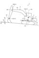
- FIG. 1 is a perspective view showing a work machine according to an embodiment.
- FIG. 2 is a schematic diagram showing a work machine according to an embodiment.
- FIG. 3 is a diagram showing a cab of a work machine according to an embodiment.
- FIG. 4 is a diagram for explaining the operation of the work machine according to the embodiment.
- FIG. 5 is a diagram for explaining the operation of the work machine according to the embodiment.
- FIG. 6 is a diagram for explaining a teaching process for setting a down rotation target position and a hoist rotation target position according to the embodiment.
- FIG. 7 is a block diagram showing a control system for a work machine according to the embodiment.
- FIG. 8 is a diagram for explaining the determination of whether automatic control is possible and the switching of the operation mode according to the embodiment.
- FIG. 9 is a flowchart showing a control method for a work machine according to the embodiment.
- FIG. 10 is a block diagram illustrating a computer system according to an embodiment.
- FIG. 11 is a block diagram showing a portion of a control system for a work machine according to another embodiment.
- FIG. 12 is a block diagram showing a portion of a control system for a work machine according to another embodiment.
- FIG. 13 is a schematic diagram showing a remote control system for a work machine according to another embodiment.
- FIG. 1 is a perspective view showing a work machine 1 according to an embodiment.
- Fig. 2 is a schematic diagram showing the work machine 1 according to an embodiment.
- Fig. 3 is a diagram showing a cab 2 of the work machine 1 according to an embodiment.
- the work machine 1 operates at a work site.
- the work machine 1 is a hydraulic excavator.
- the work machine 1 will be referred to as the hydraulic excavator 1 as appropriate.
- the hydraulic excavator 1 includes a running body 3, a rotating body 4, a work machine 5, a hydraulic cylinder 6, an operating device 7, an on-board monitor 8, an input device 9, a lock lever 10, a position sensor 11, an inertia sensor 12, an attitude sensor 13, and a control device 14.
- a three-dimensional site coordinate system (Xg, Yg, Zg) is defined at the work site.
- a three-dimensional vehicle body coordinate system (Xm, Ym, Zm) is defined on the rotating body 4.
- the site coordinate system is composed of an Xg axis extending north-south from a site reference point Og defined at the work site, a Yg axis extending east-west from the site reference point Og, and a Zg axis extending up and down from the site reference point Og.
- the site coordinate system is a global coordinate system.
- the vehicle body coordinate system is composed of the Xm axis extending in the fore-and-aft direction of the rotating body 4 from the representative point Om defined on the rotating body 4, the Ym axis extending in the left-right direction of the rotating body 4 from the representative point Om, and the Zm axis extending in the up-and-down direction of the rotating body 4 from the representative point Om.
- the +Xm direction is the front of the rotating body 4
- the -Xm direction is the rear of the rotating body 4
- the +Ym direction is the left of the rotating body 4
- the -Ym direction is the right of the rotating body 4
- the +Zm direction is above the rotating body 4
- the -Zm direction is below the rotating body 4.
- the running body 3 runs while supporting the rotating body 4.
- the running body 3 has a pair of tracks 3A.
- the running body 3 runs due to the rotation of the tracks 3A.
- the running motion of the running body 3 includes forward motion and reverse motion.
- the hydraulic excavator 1 can move around the work site using the running body 3.
- the rotating body 4 is supported by the running body 3.
- the rotating body 4 is positioned above the running body 3.
- the rotating body 4 rotates around the rotation axis RX while supported by the running body 3.
- the rotation axis RX is parallel to the Zm axis.
- the rotation of the rotating body 4 includes left rotation and right rotation.
- the driver's cab 2 is provided on the rotating body 4.
- the work machine 5 is attached to the rotating body 4.
- the work machine 5 performs work.
- the work performed by the work machine 5 includes an excavation work for excavating the excavation target 16 and an earth discharge work for discharging the excavated material to the earth discharge target 17.
- the work performed by the work machine 5 includes a loading work for moving the excavated material to the earth discharge target 17 after the excavation work, and a return work for moving toward the excavation target 16 after the earth discharge work.
- the work machine 5 includes a boom 5A, an arm 5B, and a bucket 5C as a working tool.
- the base end of the boom 5A is operably connected to the front of the rotating body 4.
- the base end of the arm 5B is operably connected to the tip of the boom 5A.
- the base end of the bucket 5C is operably connected to the tip of the arm 5B.
- Other examples of working tools include a clam bucket, tilt bucket, tilt rotate bucket, and grapple.
- the hydraulic cylinder 6 operates the work machine 5.
- the hydraulic cylinder 6 includes a boom cylinder 6A, an arm cylinder 6B, and a bucket cylinder 6C.
- the boom cylinder 6A raises and lowers the boom 5A.
- the arm cylinder 6B performs digging and dumping operations on the arm 5B.
- the bucket cylinder 6C performs digging and dumping operations on the bucket 5C.
- the base end of the boom cylinder 6A is connected to the rotating body 4.
- the tip end of the boom cylinder 6A is connected to the boom 5A.
- the base end of the arm cylinder 6B is connected to the boom 5A.
- the tip end of the arm cylinder 6B is connected to the arm 5B.
- the base end of the bucket cylinder 6C is connected to the arm 5B.
- the tip end of the bucket cylinder 6C is connected to the bucket 5C.
- the operating device 7 is disposed in the cab 2.
- the operating device 7 is operated to operate at least one of the traveling body 3, the rotating body 4, and the work machine 5.
- the operating device 7 is operated by an operator seated in the cab 2.
- the operator can operate the operating device 7 while seated in the operator's seat 15 disposed in the cab 2.
- the operating device 7 includes a left operating lever 7A and a right operating lever 7B, a left travel lever 7C and a right travel lever 7D, and a left foot pedal 7E and a right foot pedal 7F.
- the left operating lever 7A is operated to rotate the rotating body 4.
- the left operating lever 7A is also operated to operate the working machine 5.
- the right operating lever 7B is operated to operate the working machine 5.
- the rotating body 4 is operated to rotate left or right.
- the arm 5B is operated to perform a dumping or excavation operation.
- the bucket 5C is operated to perform an excavation or dumping operation.
- the boom 5A is lowered or raised.
- the rotating body 4 may be operated to rotate right or left, and when the left operating lever 7A is operated in the left-right direction, the arm 5B may be operated to perform a dumping or excavation operation.
- the rotating body 4 When the right operating lever 7B is operated in the left-right or front-rear direction, the rotating body 4 may be operated to rotate left or right.
- the left travel lever 7C and the right travel lever 7D are operated to operate the running body 3.
- the left travel lever 7C is operated in the forward or backward direction
- the left track 3A of the running body 3 moves forward or backward.
- the right travel lever 7D is operated in the forward or backward direction
- the right track 3A of the running body 3 moves forward or backward.
- the left foot pedal 7E is linked to the left travel lever 7C.
- the right foot pedal 7F is linked to the right travel lever 7D.
- the in-vehicle monitor 8 is disposed in the driver's cab 2.
- the in-vehicle monitor 8 is disposed to the right front of the driver's seat 15.
- the in-vehicle monitor 8 has a display device 8A and an input device 8B.
- the display device 8A displays specified display data. Examples of the display device 8A include a flat panel display such as a liquid crystal display (LCD) or an organic electroluminescence display (OELD).
- the input device 8B generates input data when operated by an operator. Examples of the input device 8B include a button switch, a computer keyboard, and a touch panel. Note that the display device 8A and the input device 8B may be separate entities.
- the input device 9 is disposed in the cab 2.
- the input device 9 is operated to generate a predetermined input signal.
- the input device 9 is operated by an operator in the cab 2. The operator can operate the input device 9 while seated in the cab 2 in the operator's seat 15.
- the input device 9 includes a swivel lock switch 9A, an automatic permission switch 9B, a teaching switch 9C, and an automatic start switch 9D.
- the swivel lock switch 9A and the automatic permission switch 9B are each located to the right of the driver's seat 15.
- the teaching switch 9C and the automatic start switch 9D are each located on the left operating lever 7A.
- the hydraulic excavator 1 is equipped with a swing parking brake 28 (see FIG. 7) that can stop the swing of the swing body 4 by mechanical braking force.
- the swing parking brake 28 is a hydraulic negative brake, and the brake is released by introducing pressurized oil from the solenoid valve 27.
- the swing lock switch 9A is operated by the operator to activate or release the swing parking brake 28.
- the control device 14 receives one or both of an input signal indicating that the swing lock switch 9A has been operated to activate the swing parking brake 28 and an input signal indicating that the swing lock switch 9A has been operated to release the swing parking brake 28.
- the swing parking brake 28 is activated and the swing of the swing body 4 is stopped.
- the swing parking brake 28 is activated, the swing body 4 does not swing even if the left operation lever 7A is operated so that the swing body 4 swings.
- the operator operates the swing lock switch 9A.
- the swing body 4 is not rotated, there is a high possibility that the left operation lever 7A for rotating the swing body 4 will be in a neutral state.
- the swing body 4 When the hydraulic excavator 1 works on an inclined surface, for example, if the left operation lever 7A is in a neutral state, the swing body 4 may swing due to its own weight. By operating the swing parking brake 28 by operating the swing lock switch 9A, the swing body 4 is prevented from swinging even when the left operation lever 7A is in a neutral state.
- the left operating lever 7A for rotating the rotating body 4 being in a neutral state means that when the rotating body 4 rotates as a result of the left operating lever 7A being operated in a predetermined direction, the left operating lever 7A is in a neutral state at least in a predetermined direction.
- the left operating lever 7A being in a neutral state means that at least the left operating lever 7A is in a neutral state in the left-right direction.
- the left operating lever 7A being in a neutral state means that at least the left operating lever 7A is in a neutral state in the front-rear direction.
- the automatic permission switch 9B is operated to permit automatic control of the rotating body 4 and the work machine 5.
- the teaching switch 9C is operated to set the target position of the bucket 5C in automatic control.
- the target positions of the bucket 5C include the excavation target position 16R, the soil discharge target position 17R, and the intermediate target position 18R, which will be described later.
- the automatic start switch 9D is operated to start automatic control.
- the lock lever 10 is operated to disable each of the rotating body 4 and the work machine 5.
- the lock lever 10 is provided in the cab 2.
- the lock lever 10 is arranged in the boarding passage connecting the entrance and exit of the cab 2 and the cab seat 15.
- the lock lever 10 is rotatably supported on the floor of the cab 2.
- the lock lever 10 is operated to move between a locked position and a free position.
- the control device 14 receives one or both of an operation signal indicating that the lock lever 10 has been operated to the locked position and an operation signal indicating that the lock lever 10 has been operated to the free position.
- An operator outside the cab 2 can sit in the operator's seat 15 after passing through the open boarding passage. After sitting in the operator's seat 15, the operator operates the lock lever 10 to the free position. By operating the lock lever 10 to the free position, the rotating body 4 and the work machine 5 are both in a free state. The operator can operate the operating device 7 to perform work.
- the lock lever 10 When the operator sitting in the driver's seat 15 leaves the driver's cab 2, he or she operates the lock lever 10 to the locked position so that the boarding passage is open. The operator can leave the driver's cab 2 by passing through the open boarding passage. By operating the lock lever 10 to the locked position, the rotating body 4 and the work machine 5 are each locked. Since the rotating body 4 and the work machine 5 are each locked, the rotating body 4 and the work machine 5 are prevented from moving when the operator is not present in the driver's cab 2.
- the position sensor 11 detects a position in the site coordinate system.
- the position sensor 11 detects a position in the site coordinate system using a Global Navigation Satellite System (GNSS).
- the Global Navigation Satellite System includes a Global Positioning System (GPS).
- GPS Global Positioning System
- the Global Navigation Satellite System detects a position defined by coordinate data of latitude, longitude, and altitude.
- the position sensor 11 includes a GNSS receiver that receives GNSS radio waves from a GNSS satellite.
- the position sensor 11 is disposed on the rotating body 4.
- the position sensor 11 includes a first position sensor 11A and a second position sensor 11B.
- the first position sensor 11A and the second position sensor 11B are arranged at different positions on the rotating body 4. In the embodiment, the first position sensor 11A and the second position sensor 11B are arranged at a distance in the left-right direction on the rotating body 4.
- the first position sensor 11A detects a first positioning position indicating the position where the first position sensor 11A is arranged.
- the second position sensor 11B detects a second positioning position indicating the position where the second position sensor 11B is arranged.
- the orientation of the rotating body 4 is calculated based on the detection data of the first position sensor 11A and the detection data of the second position sensor 11B.
- the inertial sensor 12 detects the acceleration and angular velocity of the rotating body 4.
- the inertial sensor 12 includes an inertial measurement unit (IMU).
- the inertial sensor 12 is disposed on the rotating body 4.
- the inertial sensor 12 can detect the rotation speed of the rotating body 4.
- the attitude sensor 13 detects the attitude of the work machine 5.
- the attitude of the work machine 5 includes the angle of the work machine 5.
- the attitude sensor 13 is provided on the work machine 5.
- the attitude sensor 13 includes a boom attitude sensor 13A that detects the attitude of the boom 5A, an arm attitude sensor 13B that detects the attitude of the arm 5B, and a bucket attitude sensor 13C that detects the attitude of the bucket 5C.
- the boom attitude sensor 13A detects, for example, the angle of the boom 5A relative to the rotation axis RX.
- the arm attitude sensor 13B detects the angle of the arm 5B relative to the boom 5A.
- the bucket attitude sensor 13C detects the angle of the bucket 5C relative to the arm 5B.
- An example of the attitude sensor 13 is a potentiometer.
- the attitude sensor 13 may be a stroke sensor that detects the stroke of the hydraulic cylinders 6 (boom cylinder 6A, arm cylinder 6B, bucket cylinder 6C). Furthermore, if an IMU is attached to each of the boom 5A, arm 5B, and bucket 5C, the IMU may detect the angle of each of the boom 5A, arm 5B, and bucket 5C.
- [Work machine operation] 4 and 5 are diagrams for explaining the operation of the hydraulic excavator 1 according to the embodiment.
- the hydraulic excavator 1 repeats an excavation operation, a hoist rotation operation, an earth discharge operation, and a down rotation operation.
- the excavation operation refers to an operation of excavating the excavation target 16 with the bucket 5C in a state in which the front surface of the revolving body 4 faces the excavation target 16.
- the hoist rotation operation refers to an operation in which an operation of raising the working implement 5 and an operation of rotating the revolving body 4 are performed together.
- the hoist rotation operation includes an operation in which an operation of raising the boom 5A and an operation of rotating the revolving body 4 are performed together.
- the hoist rotation operation refers to an operation in which, after the excavation target 16 is excavated with the bucket 5C, the working implement 5 is operated and the revolving body 4 is rotated so that the front surface of the revolving body 4 faces the earth discharge target 17 and the bucket 5C holding the excavated material is positioned above the earth discharge target 17.
- the earth discharge operation refers to an operation of discharging the excavated material held by the bucket 5C to the earth discharge target 17 with the front surface of the revolving body 4 facing the earth discharge target 17.
- the down rotation operation refers to an operation in which the operation of lowering the working implement 5 and the operation of rotating the revolving body 4 are performed together.
- the down rotation operation includes an operation in which the operation of lowering the boom 5A and the operation of rotating the revolving body 4 are performed together.
- the down rotation operation refers to an operation in which, after discharging the excavated material from the bucket 5C to the earth discharge target 17, the working implement 5 is operated and the revolving body 4 is rotated so that the front surface of the revolving body 4 faces the excavation target 16 and the bucket 5C is placed on the excavation target 16.
- An example of the earth discharge target 17 is the vessel of a dump truck.
- Other examples of the earth discharge target 17 include a hopper, a self-propelled soil improvement machine, and a belt conveyor.
- the hoist rotation operation and the down rotation operation are examples of combined operations that include the operation of the work machine 5 and the operation of the rotating body 4.
- the operation of the work machine 5 in the combined operation includes the operation of the boom 5A.
- the operation of the boom 5A in the combined operation includes the raising operation of the boom 5A or the lowering operation of the boom 5A.
- the operation modes of the rotating body 4 and the work machine 5 include a manual mode and an automatic mode.
- the operation modes of the rotating body 4 and the work machine 5 can be switched between a manual mode and an automatic mode.
- the manual mode is an operation mode in which the rotating body 4 and the work machine 5 each operate based on the operation of the operation device 7 by the operator.
- the manual mode is an operation mode in which the rotating body 4 and the work machine 5 each operate manually.
- the automatic mode is an operation mode in which the rotating body 4 and the work machine 5 each operate based on an automatic control command output from the control device 14, not based on the operation of the operation device 7.
- the automatic mode is an operation mode in which the rotating body 4 and the work machine 5 each are automatically controlled.
- the automatic mode may also be an operation mode in which either the rotating body 4 or the work machine 5 operates based on an automatic control command output from the control device 14.
- the operating mode for excavation operation which is an example of excavation work, is the manual mode.
- the rotating body 4 and the work machine 5 are each manually operated.
- the operating mode of the hoist rotation operation which is an example of loading operation, is the automatic mode.
- the rotating body 4 and the work machine 5 are each automatically controlled.
- the automatic start switch 9D is operated to transition from the manual mode to the automatic mode.
- the automatic control of the rotating body 4 and the work machine 5 is started.
- the rotating body 4 automatically rotates and the work machine 5 automatically operates so that the bucket 5C is positioned at the soil discharge target position 17R set in the soil discharge target 17.
- the boom 5A is raised so that the excavated material held in the bucket 5C does not spill out of the bucket 5C.
- the automatic mode transitions from the automatic mode to the manual mode.
- the automatic control of the rotating body 4 and the work machine 5 is released.
- the automatic control of the rotating body 4 and the work machine 5 may also be released by the operator operating the operation device 7.
- the operating mode for the soil discharge operation which is an example of soil discharge work, is the manual mode.
- the rotating body 4 and the work machine 5 are each manually operated. After the bucket 5C reaches the soil discharge target position 17R and the automatic control of the rotating body 4 and the work machine 5 is released, the operator can operate the operating device 7 to carry out the soil discharge operation using the work machine 5 including the bucket 5C.
- the operation mode of the down swing operation which is an example of the return operation, is the automatic mode.
- the rotating body 4 and the working machine 5 are automatically controlled.
- the automatic start switch 9D is operated to transition from the manual mode to the automatic mode.
- the automatic control of the rotating body 4 and the working machine 5 is started.
- the rotating body 4 automatically swings and the working machine 5 automatically operates so that the bucket 5C is placed at the excavation target position 16R set in the excavation target 16.
- the boom 5A is lowered.
- the automatic mode transitions to the manual mode.
- the operator can operate the operating device 7 to perform the excavation operation.
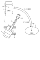
- [Teaching process] 6 is a diagram for explaining a teaching process for setting the excavation target position 16R and the earth discharge target position 17R according to the embodiment.
- the excavation target position 16R and the earth discharge target position 17R are set by the teaching process.
- the operator When setting the excavation target position 16R, the operator operates the operating device 7 to place the bucket 5C at any position on the excavation target 16, and then operates the teaching switch 9C.
- the control device 14 stores the position of the bucket 5C at the time the teaching switch 9C is operated as the excavation target position 16R.
- the position of the bucket 5C is determined based on the orientation of the rotating body 4 and the attitude of the work machine 5.
- the control device 14 stores the orientation of the rotating body 4 and the attitude of the work machine 5 at the time the teaching switch 9C is operated as position data related to the excavation target position 16R.
- the orientation of the rotating body 4 is calculated based on the detection data of the first position sensor 11A and the detection data of the second position sensor 11B.
- the attitude of the work machine 5 is detected by the attitude sensor 13.
- the control device 14 stores the detection data of the position sensor 11 (11A, 11B) and the detection data of the attitude sensor 13 (13A, 13B, 13C) at the time the teaching switch 9C is operated as position data related to
- the operator When setting the soil discharge target position 17R, the operator operates the operation device 7 to place the bucket 5C in a position above the soil discharge target 17, and then operates the teaching switch 9C.
- the control device 14 stores the position of the bucket 5C at the time the teaching switch 9C is operated as the soil discharge target position 17R.
- the control device 14 stores the orientation of the rotating body 4 and the attitude of the work machine 5 at the time the teaching switch 9C is operated as position data related to the soil discharge target position 17R.
- the control device 14 stores the detection data of the position sensors 11 (11A, 11B) and the detection data of the attitude sensors 13 (13A, 13B, 13C) at the time the teaching switch 9C is operated as position data related to the soil discharge target position 17R.
- an intermediate target position 18R is set.
- the intermediate target position 18R is set between the excavation target position 16R and the soil discharge target position 17R.
- the intermediate target position 18R is set at a position away from the soil discharge target 17.
- the intermediate target position 18R is set at a position where the bucket 5C does not contact the soil discharge target 17.
- the operator operates the operation device 7 to place the bucket 5C at a position between the excavation target position 16R and the soil discharge target position 17R where it does not contact the soil discharge target 17, and then operates the teaching switch 9C.
- the control device 14 stores the position of the bucket 5C at the time the teaching switch 9C is operated as the intermediate target position 18R.
- the control device 14 stores the direction of the rotating body 4 and the attitude of the work implement 5 at the time the teaching switch 9C is operated as position data related to the intermediate target position 18R.
- the control device 14 stores the detection data of the position sensor 11 (11A, 11B) and the detection data of the attitude sensor 13 (13A, 13B, 13C) at the time when the teaching switch 9C is operated as position data related to the intermediate target position 18R.
- the control device 14 sets a first path 19A connecting the excavation target position 16R and the intermediate target position 18R, and a second path 19B connecting the intermediate target position 18R and the soil discharge target position 17R.
- the control device 14 controls the attitude of the work machine 5 so that the bucket 5C passes through the first path 19A and the second path 19B when the rotating body 4 rotates.
- the control device 14 controls the hydraulic cylinder 6 so that the work machine 5 operates on the first path 19A and does not operate on the second path 19B.
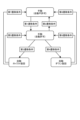
- Control System 7 is a block diagram showing a control system 50 of the work machine 1 according to the embodiment.
- the hydraulic excavator 1 is equipped with the control system 50.
- the control system 50 has an operation device 7, an input device 9, a lock lever 10, a position sensor 11, an inertial sensor 12, an attitude sensor 13, and a control device 14.
- the control device 14 controls the hydraulic excavator 1.
- the control device 14 includes a computer system.
- the operation device 7, the input device 9, the lock lever 10, the position sensor 11, the inertial sensor 12, and the attitude sensor 13 are each connected to the control device 14.
- the operation device 7 which includes the left operation lever 7A and the right operation lever 7B, generates an operation signal when operated by an operator.
- the operation signal generated by the operation device 7 is input to the control device 14.
- the input device 9, which includes the swing lock switch 9A, the automatic permission switch 9B, the teaching switch 9C, and the automatic start switch 9D, generates an input signal when operated by an operator.
- the input signal generated by the input device 9 is input to the control device 14.
- the swing lock switch 9A is disposed between the control device 14 and the solenoid valve 27. As described above, the control device 14 receives one or both of an input signal indicating that the swing lock switch 9A has been operated so that the swing parking brake 28 is in an actuated state and an input signal indicating that the swing lock switch 9A has been operated so that the swing parking brake 28 is in a released state.
- the lock lever 10 generates an operation signal when operated by an operator.
- the operation signal generated in the lock lever 10 is input to the control device 14.
- the control device 14 receives one or both of an operation signal indicating that the lock lever 10 has been operated to the locked position and an operation signal indicating that the lock lever 10 has been operated to the free position.
- Detection data from the inertial sensor 12 is input to the control device 14.
- the control system 50 also includes an EPC valve 20, a main valve 21, an engine 22, a hydraulic pump 23, a hydraulic cylinder 6, a swing motor 24, and a swing parking brake 28.
- the swing motor 24 is a hydraulic motor.
- the swing motor 24 generates power to swing the swing body 4.
- the engine 22 is the power source of the hydraulic excavator 1.
- the hydraulic pump 23 is driven by the engine 22.
- the hydraulic pump 23 discharges hydraulic oil for operating each of the hydraulic cylinder 6 and the swing motor 24.
- the main valve 21 is connected to the hydraulic pump 23.
- the hydraulic pump 23 supplies hydraulic oil to each of the hydraulic cylinder 6 and the swing motor 24 via the main valve 21.
- the main valve 21 has a spool.
- the direction and flow rate of the hydraulic oil supplied from the hydraulic pump 23 to the hydraulic cylinder 6 are adjusted by moving the spool of the main valve 21.
- the main valve 21 can extend or retract the boom cylinder 6A, for example, by adjusting the direction of the hydraulic oil supplied to the boom cylinder 6A.
- the main valve 21 can adjust the operating speed of the boom cylinder 6A by adjusting the flow rate of hydraulic oil supplied to the boom cylinder 6A. The same applies to the arm cylinder 6B and the bucket cylinder 6C.
- the direction and flow rate of hydraulic oil supplied from the hydraulic pump 23 to the swing motor 24 are adjusted by moving the spool of the main valve 21.
- the main valve 21 can adjust the rotation direction of the swing motor 24 so that the swing body 4 swings left or right by adjusting the direction of the hydraulic oil supplied to the swing motor 24.
- the main valve 21 can adjust the rotation speed of the swing motor 24 by adjusting the flow rate of hydraulic oil supplied to the swing motor 24.
- the EPC valve 20 provides the main valve 21 with a pilot pressure for moving the spool of the main valve 21.
- the EPC valve 20 adjusts the pilot pressure based on a control command from the control device 14.
- the swing parking brake 28 can stop the rotation of the swing body 4.
- the swing parking brake 28 is activated, a mechanical braking force of the swing parking brake 28 is generated, and the swing of the swing body 4 is stopped.
- the operation of the swing parking brake 28 is released, the braking force of the swing parking brake 28 is released, and the swing body 4 becomes able to swing.
- the swing parking brake 28 includes a negative disc brake.
- the swing parking brake 28 includes a pair of brake discs 25, a brake cylinder 26, and a solenoid valve 27. When the solenoid valve 27 is driven and the brake cylinder 26 contracts, the pair of brake discs 25 move away from each other, and the operation of the swing parking brake 28 is released.
- the brake cylinder 26 extends due to the elastic force of a spring provided in the brake cylinder 26.
- the brake cylinder 26 extends, the pair of brake discs 25 come into contact with each other, and the swing parking brake 28 is activated.
- the control device 14 has a position calculation unit 141, a teaching unit 142, a target position memory unit 143, an automatic permission unit 144, a mode determination unit 145, a manual control command unit 146, an automatic control command unit 147, a control command switching unit 148, an operation control unit 149, and a brake control unit 150.
- the position calculation unit 141 calculates the position of the bucket 5C based on the detection data of the position sensor 11 and the detection data of the attitude sensor 13.
- the position calculation unit 141 calculates the orientation of the rotating body 4 based on the detection data of the first position sensor 11A and the detection data of the second position sensor 11B.
- the position calculation unit 141 calculates the position of the bucket 5C relative to the rotating body 4 based on the detection data of the attitude sensor 13 and the dimensional data of the work machine 5.
- the dimensional data of the work machine 5 includes the length of the boom 5A, the length of the arm 5B, and the length of the bucket 5C.
- the dimensional data of the work machine 5 is known data.
- the position calculation unit 141 can calculate the position of the bucket 5C in, for example, the vehicle body coordinate system based on the orientation of the rotating body 4 and the position of the bucket 5C relative to the rotating body 4.
- the teaching unit 142 calculates the positions of the excavation target position 16R, the soil discharge target position 17R, and the intermediate target position 18R based on the position of the bucket 5C at the time of receiving an input signal from the teaching switch 9C. As described with reference to FIG. 6, the excavation target position 16R, the soil discharge target position 17R, and the intermediate target position 18R are each set in the teaching process. When setting the excavation target position 16R, the bucket 5C is placed at an arbitrary position on the excavation target 16 by operating the operation device 7, and then the teaching switch 9C is operated. The teaching unit 142 calculates the position of the bucket 5C at the time of receiving an input signal from the teaching switch 9C as the excavation target position 16R.
- the bucket 5C When setting the soil discharge target position 17R, the bucket 5C is placed at a position above the soil discharge target 17 by operating the operation device 7, and then the teaching switch 9C is operated.
- the teaching unit 142 calculates the position of the bucket 5C at the time of receiving an input signal from the teaching switch 9C as the soil discharge target position 17R.
- the bucket 5C When setting the intermediate target position 18R, the bucket 5C is placed at a position that does not contact the soil discharge target 17 by operating the operating device 7, and then the teaching switch 9C is operated.
- the teaching unit 142 calculates the position of the bucket 5C at the time of receiving an input signal from the teaching switch 9C as the intermediate target position 18R.
- the teaching unit 142 sets the excavation target position 16R to the excavation target 16, sets the soil discharge target position 17R to the soil discharge target 17, and sets the intermediate target position 18R between the excavation target position 16R and the soil discharge target position 17R.
- the teaching unit 142 also sets the first path 19A and the second path 19B.
- guidance to prompt the operator to set them may be output to the cab 2.
- the operator may set the excavation target position 16R, the soil discharge target position 17R, and the intermediate target position 18R by operating the input device 8B based on the guidance.
- the guidance to prompt the operator to set them may be displayed on the display device 8A. If an audio output device that outputs sound is arranged in the cab 2, the guidance to prompt the operator to set them may be output from the audio output device.
- the target position memory unit 143 stores the excavation target position 16R set on the excavation target 16, the soil discharge target position 17R set on the soil discharge target 17, and the intermediate target position 18R set between the excavation target position 16R and the soil discharge target position 17R.
- the target position memory unit 143 also stores the first path 19A and the second path 19B.
- the automatic permission unit 144 determines whether or not automatic control of the rotating body 4 and the work machine 5 is possible based on the operation state of the swing lock switch 9A.
- the automatic permission unit 144 does not permit automatic control when the swing lock switch 9A is operated. That is, when the swing lock switch 9A is ON and the swing parking brake 28 is activated, the automatic permission unit 144 does not permit automatic control based on the input signal from the swing lock switch 9A.
- the automatic permission unit 144 permits automatic control when the swing lock switch 9A is not operated. That is, when the swing lock switch 9A is OFF and the swing parking brake 28 is released, the automatic permission unit 144 permits automatic control.
- the mode determination unit 145 determines the operation mode of the rotating body 4 and the work machine 5 based on predetermined transition conditions.
- the manual control command unit 146 generates a manual control command for operating at least one of the rotating body 4 and the work machine 5 based on an operation signal from at least one of the left operation lever 7A and the right operation lever 7B. In the manual mode, the manual control command unit 146 outputs the manual control command to the control command switching unit 148.
- the automatic control command unit 147 generates automatic control commands to automatically control the rotating body 4 and the work machine 5. In the automatic mode, the automatic control command unit 147 outputs the automatic control commands to the control command switching unit 148.
- the control command switching unit 148 receives a manual control command from the manual control command unit 146 and an automatic control command from the automatic control command unit 147.
- the control command switching unit 148 outputs one of the manual control command and the automatic control command to the brake control unit 150.
- the control command switching unit 148 outputs one of the manual control command and the automatic control command to the operation control unit 149.
- the manual control command is output from the control command switching unit 148.
- the automatic control command is output from the control command switching unit 148.
- the brake control unit 150 controls the swing parking brake 28.
- the brake control unit 150 controls the swing parking brake 28 based on the operation state of the left operating lever 7A operated to rotate the swing body 4, or the output state of the automatic control command from the automatic control command unit 147.
- the brake control unit 150 may also control the swing parking brake 28 based on the operation state of the operating levers (7A, 7B) operated to operate the work machine 5. For example, the brake control unit 150 releases the swing parking brake 28 when the operating levers (7A, 7B) for operating the work machine 5 are operated.
- the brake control unit 150 activates the slewing parking brake 28 based on the input signal from the slewing lock switch 9A.
- the brake control unit 150 activates the swing parking brake 28.
- the manual control command unit 146 outputs a manual control command indicating that the operation state of the left operating lever 7A satisfies the brake operation condition to the control command switching unit 148 based on an operation signal from the left operating lever 7A.
- the control command switching unit 148 outputs a manual control command indicating that the operation state of the left operating lever 7A satisfies the brake operation condition to the brake control unit 150.
- the brake operation condition includes the neutral state of the left operating lever 7A operated to rotate the rotating body 4 elapses for a predetermined time that is set in advance.
- the neutral state of the left operating lever 7A refers to a state in which an operation signal for rotating the rotating body 4 is not output from the left operating lever 7A.
- the neutral state of the left operating lever 7A may be a state in which an operation signal for not rotating the rotating body 4 is output from the left operating lever 7A.
- the neutral state of the left operating lever 7A refers to a state in which the left operating lever 7A is located in the center position in the left or right direction.
- the predetermined time is, for example, 5 seconds.
- the brake control unit 150 activates the swing parking brake 28.
- the brake control unit 150 controls the swing parking brake 28 based on the automatic control command output from the automatic control command unit 147, not based on the operation state of the left operating lever 7A.
- the control command switching unit 148 outputs the automatic control command from the automatic control command unit 147 to the brake control unit 150.
- the automatic mode it is highly likely that the operator will not move the left operating lever 7A or the right operating lever 7B, or will take their hands off the left operating lever 7A or the right operating lever 7B. In other words, in the automatic mode, it is highly likely that the left operating lever 7A will be maintained in a neutral state.
- the swing parking brake 28 In the automatic mode, if the left operating lever 7A remains in a neutral state for 5 seconds, the swing parking brake 28 will be activated. In this embodiment, the swing parking brake 28 operates when the left operating lever 7A is in a neutral state for 5 seconds in manual mode, but the swing parking brake 28 does not operate even if the left operating lever 7A is in a neutral state for 5 seconds in automatic mode.
- the operation control unit 149 controls the revolving body 4 and the work machine 5.
- the manual control command unit 146 generates a manual control command based on an operation signal from at least one of the left operation lever 7A and the right operation lever 7B.
- the control command switching unit 148 outputs the manual control command generated in the manual control command unit 146 to the operation control unit 149.
- the automatic control command unit 147 generates an automatic control command.
- the control command switching unit 148 outputs the automatic control command generated in the automatic control command unit 147 to the operation control unit 149.
- the operation control unit 149 drives the EPC valve 20 based on the manual control command supplied from the control command switching unit 148.
- the operation control unit 149 drives the EPC valve 20 based on the automatic control command supplied from the control command switching unit 148.
- the operation control unit 149 supplies an EPC current for driving the EPC valve 20 to the EPC valve 20.
- the EPC valve 20 applies pilot pressure to the spool of the main valve 21 based on the EPC current supplied from the operation control unit 149.
- the operation control unit 149 cuts the base pressure to the EPC valve 20 based on the operation signal from the lock lever 10, and the oil discharged from the hydraulic pump is blocked by the control valve. By cutting the base pressure, the main valve 21 becomes inoperable. By making the main valve 21 inoperable, a locked state is entered in which the rotating body 4 and the work machine 5 are both inoperable.
- the drive of the control valve may be controlled by another control device, etc.
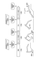
- [Determining whether automatic control is possible] 8 is a diagram for explaining the determination of whether automatic control is possible and switching of the operation mode according to the embodiment.
- automatic control is not permitted in the manual mode and the first transition condition is not satisfied.
- automatic control is not permitted in the manual mode and the first transition condition is satisfied.
- the first transition condition includes that the turning lock switch 9A is not operated.
- the automatic permission unit 144 does not permit automatic control.
- the automatic permission unit 144 permits automatic control.
- the first transition condition may include that the slewing lock switch 9A is not operated and that the lock lever 10 is operated to the free position. That is, the automatic permission unit 144 may determine whether or not automatic control is possible based on the operation state of the slewing lock switch 9A and the operation state of the lock lever 10. For example, the automatic permission unit 144 does not permit automatic control in the manual mode when the slewing parking brake 28 is activated by the operation of the slewing lock switch 9A and the slewing body 4 and the work machine 5 are in a locked state due to the movement of the lock lever 10 to the locked position.
- the automatic permission unit 144 permits automatic control in the manual mode when the slewing parking brake 28 is not activated due to the non-operation of the slewing lock switch 9A and the slewing body 4 and the work machine 5 are in a free state due to the movement of the lock lever 10 to the free position.
- the first transition condition may include that the rotation lock switch 9A is not operated, that the lock lever 10 is operated to the free position, that the automatic permission switch 9B is operated, that the GNSS is available, and that the target positions in the automatic control (excavation target position 16R, soil discharge target position 17R, intermediate target position 18R) have been set.
- the first transition condition may be at least one of that the rotation lock switch 9A is not operated, that the lock lever 10 is operated to the free position, that the automatic permission switch 9B is operated, that the GNSS is available, and that the target positions in the automatic control (excavation target position 16R, soil discharge target position 17R, intermediate target position 18R) have been set.
- the second transition condition includes that the rotation lock switch 9A has been operated.
- the second transition condition may be that the rotation lock switch 9A has been operated, or that the lock lever 10 has been operated to the locked position.
- the second transition condition may include at least one of that the rotation lock switch 9A has been operated, that the lock lever 10 has been operated to the locked position, that the automatic permission switch 9B has not been operated, that the GNSS is not available, and that the target positions (excavation target position 16R, soil removal target position 17R, intermediate target position 18R) in automatic control have not been set. For example, ionospheric scintillation, etc. may cause the GNSS to become unusable.
- the automatic control command unit 147 outputs an automatic control command when the automatic start switch 9D is operated while automatic control is permitted in the manual mode. In other words, when the automatic start switch 9D is operated while automatic control is permitted in the manual mode, a transition from the manual mode to the automatic mode occurs.
- the third transition condition includes the automatic start switch 9D being operated when the bucket 5C is positioned near the excavation target 16.
- the automatic control command unit 147 outputs an automatic control command based on the input signal from the automatic start switch 9D so that the bucket 5C of the work machine 5 moves to the soil discharge target position 17R.
- the fourth transition condition includes the automatic start switch 9D being operated when the bucket 5C is positioned near the soil discharge target 17.
- the automatic control command unit 147 outputs an automatic control command based on the input signal from the automatic start switch 9D so that the bucket 5C of the work machine 5 moves to the excavation target position 16R.
- a fifth transition condition includes at least one of the following: the bucket 5C of the work machine 5 has reached the soil discharge target position 17R, and the operating device 7 has been operated during the hoist rotation operation.
- a sixth transition condition is met while a down swing operation is being performed in automatic mode, the automatic mode transitions to a manual mode in which automatic control is permitted.
- the sixth transition condition includes at least one of the following: the bucket 5C of the work machine 5 has reached the excavation target position 16R, and the operating device 7 has been operated during the down swing operation.
- the seventh transition condition includes the satisfaction of the second transition condition, such as the unavailability of the GNSS.
- the eighth transition condition includes the satisfaction of the second transition condition, such as the unavailability of GNSS.
- the mode determination unit 145 can determine the operation mode of the rotating body 4 and the work machine 5 based on each of the first transition condition to the eighth transition condition.
- Fig. 9 is a flowchart showing a control method for the hydraulic excavator 1 according to the embodiment.
- the automatic permission unit 144 determines whether or not the first transition condition described with reference to Fig. 8 is satisfied. In the embodiment, the automatic permission unit 144 determines whether or not automatic control is possible based on the operation state of the swing lock switch 9A (step S1).
- the automatic permission unit 144 permits automatic control when the rotation lock switch 9A is not operated.
- the automatic permission unit 144 does not permit automatic control when the rotation lock switch 9A is operated.
- step S1 determines whether the third transition condition or the fourth transition condition described with reference to FIG. 8 is satisfied. In the embodiment, if it is determined in step S1 that automatic control is permitted, the mode determination unit 145 determines whether the automatic start switch 9D has been operated (step S2).
- step S2 If it is determined in step S2 that the automatic start switch 9D has been operated (step S2: Yes), the mode transitions from manual mode to automatic mode.
- the mode determination unit 145 determines whether the fifth transition condition, the sixth transition condition, the seventh transition condition, or the eighth transition condition described with reference to FIG. 8 is satisfied. In the embodiment, the mode determination unit 145 determines whether the operating device 7 has been operated (step S3).
- step S3 If it is determined in step S3 that the operating device 7 has not been operated (step S3: No), the automatic control command unit 147 outputs an automatic control command for the hoist rotation operation or the down rotation operation to the operation control unit 149 via the control command switching unit 148 (step S4).
- the brake control unit 150 receives the automatic control command output from the automatic control command unit 147 via the control command switching unit 148. The brake control unit 150 judges whether the automatic control command satisfies the brake actuation conditions. In the automatic mode, an automatic control command corresponding to the neutral state of the left operating lever 7A may be output from the automatic control command unit 147. Also, in the automatic mode, an automatic control command that satisfies the brake actuation conditions may be output from the automatic control command unit 147. The brake control unit 150 judges whether the neutral state of the automatic control command for rotating the rotating body 4 has lasted for 5 seconds (step S5).
- step S5 If it is determined in step S5 that the neutral state of the automatic control command has not elapsed for 5 seconds (step S5: No), the swing parking brake 28 is not activated.
- the mode determination unit 145 determines whether the bucket 5C has reached the target position (earth removal target position 17R or excavation target position 16R) (step S6).
- step S6 determines whether or not to end the operation of the hydraulic excavator 1 (step S7).
- step S7 If it is determined in step S7 that the work of the hydraulic excavator 1 is to be ended (step S7: Yes), the work of the hydraulic excavator 1 is ended. If it is determined in step S7 that the work of the hydraulic excavator 1 is not to be ended (step S7: No), the process returns to step S1.
- step S1 If it is determined in step S1 that the rotation lock switch 9A has been operated, i.e., if it is determined that automatic control is not permitted (step S1: No), the manual mode is maintained. Also, if it is determined in step S2 that the automatic start switch 9D has not been operated (step S2: No), the manual mode is maintained. Also, if it is determined in step S3 that the operating device 7 has been operated (step S3: Yes), a transition from the automatic mode to the manual mode occurs.
- the manual control command unit 146 In the manual mode, the manual control command unit 146 generates a manual control command based on the operation signals from the left operating lever 7A and the right operating lever 7B. The manual control command unit 146 outputs a manual control command to each of the brake control unit 150 and the operation control unit 149 via the control command switching unit 148 (step S8).
- the brake control unit 150 receives the manual control command from the manual control command unit 146 via the control command switching unit 148. The brake control unit 150 determines whether the neutral state of the manual control command for rotating the rotating body 4 has elapsed for 5 seconds (step S9). The neutral state of the manual control command corresponds to the neutral state of the left operating lever 7A.
- step S9 If it is determined in step S9 that the neutral state of the manual control command has not elapsed for 5 seconds (step S9: No), the turning parking brake 28 is not activated and the process proceeds to step S7.
- step S5 If it is determined in step S5 that the neutral state of the automatic control command has continued for 5 seconds (step S5: Yes), the brake control unit 150 activates the turning parking brake 28 (step S10).
- the brake control unit 150 determines whether the left operating lever 7A, which is operated to rotate the rotating body 4, has been operated (step S11).
- step S11 If it is determined in step S11 that the left operating lever 7A has not been operated (step S11: No), the process returns to step S10, and the brake control unit 150 continues to operate the swing parking brake 28. If it is determined in step S11 that the left operating lever 7A has been operated (step S11: Yes), the swing parking brake 28 is released, and the process proceeds to step S6.
- step S9 If it is determined in step S9 that the neutral state of the manual control command has continued for 5 seconds (step S9: Yes), the brake control unit 150 activates the turning parking brake 28 (step S12).
- the brake control unit 150 determines whether the left operating lever 7A, which is operated to rotate the rotating body 4, has been operated (step S13).
- step S13 If it is determined in step S13 that the left operating lever 7A has not been operated (step S13: No), the process returns to step S12, and the brake control unit 150 continues to operate the swing parking brake 28. If it is determined in step S13 that the left operating lever 7A has been operated (step S13: Yes), the swing parking brake 28 is released, and the process proceeds to step S7.
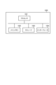
- FIG. 10 is a block diagram showing a computer system 1000 according to an embodiment.
- the above-mentioned control device 14 includes the computer system 1000.
- the computer system 1000 has a processor 1001 such as a CPU (Central Processing Unit), a main memory 1002 including a non-volatile memory such as a ROM (Read Only Memory) and a volatile memory such as a RAM (Random Access Memory), a storage 1003, and an interface 1004 including an input/output circuit.
- the functions of the above-mentioned control device 14 are stored in the storage 1003 as a computer program.
- the processor 1001 reads the computer program from the storage 1003, expands it in the main memory 1002, and executes the above-mentioned processing according to the program.
- the computer program may be distributed to the computer system 1000 via a network.
- the computer program or computer system 1000 can execute the following operations according to the above-described embodiment: obtain the operation state of the rotation lock input device that is operated to activate the rotation parking brake 28 that can stop the rotation of the rotating body 4; and determine whether or not the rotating body 4 and the work machine 5 attached to the rotating body 4 can be automatically controlled based on the operation state of the rotation lock input device.
- the hydraulic excavator 1 comprises a rotating body 4, a work machine 5 attached to the rotating body 4, a swing parking brake 28 capable of stopping the rotation of the rotating body 4, a swing lock switch 9A (swing lock input device) that is operated to activate the swing parking brake 28, an automatic control command unit 147 that outputs an automatic control command to automatically control the rotating body 4 and the work machine 5, and an automatic permission unit 144 that determines whether or not automatic control of the rotating body 4 and the work machine 5 is possible based on the operation state of the swing lock switch 9A.
- swing lock switch 9A swing lock input device
- the operating state of the swing lock switch 9A is taken into consideration in determining whether or not automatic control of the rotating body 4 and the work machine 5 is possible, so that a decrease in the work efficiency of the hydraulic excavator 1 is suppressed.
- the swing parking brake 28 is activated and the rotating body 4 cannot be rotated. If automatic control of the rotating body 4 and the work machine 5 is started with the swing lock switch 9A operated, a situation may occur in which the work machine 5 operates with the rotating body 4 not rotating.
- the automatic permission unit 144 does not permit automatic control based on the input signal from the swing lock switch 9A.
- the automatic permission unit 144 does not permit automatic control when the swing lock switch 9A is operated.
- the automatic permission unit 144 permits automatic control when the swing lock switch 9A is not operated.
- the hydraulic excavator 1 can transition from manual mode to automatic mode.
- the hydraulic excavator 1 is equipped with an automatic start switch 9D (automatic start input device) that is operated to start automatic control.
- the automatic control command unit 147 outputs an automatic control command based on an input signal from the automatic start switch 9D.
- the automatic control command is output from the automatic control command unit 147, the rotating body 4 and the work machine 5 are automatically controlled.
- the teaching unit 142 sets the excavation target position 16R for the excavation target 16 and sets the soil discharge target position 17R for the soil discharge target 17.
- the target position memory unit 143 stores the excavation target position 16R set for the excavation target 16 and the soil discharge target position 17R set for the soil discharge target 17.
- the automatic control command unit 147 outputs an automatic control command so that the bucket 5C of the work machine 5 moves to the excavation target position 16R.
- the automatic control command unit 147 outputs an automatic control command so that the bucket 5C of the work machine 5 moves to the soil discharge target position 17R.
- the automatic control command unit 147 outputs an automatic control command so that the bucket 5C moves to the soil discharge target position 17R in the hoist rotation operation.
- the automatic control command unit 147 outputs an automatic control command so that the bucket 5C moves to the soil discharge target position 16R in the down rotation operation. This reduces the burden on the operator.
- the hydraulic excavator 1 is equipped with a lock lever 10 (operation lock operating device) that is operated to disable each of the rotating body 4 and the work machine 5.
- the automatic permission unit 144 may determine whether or not automatic control is possible based on the operation state of the lock lever 10. When the lock lever 10 is operated, each of the rotating body 4 and the work machine 5 becomes inoperable, so even if an automatic control command is output from the automatic control command unit 147, automatic control of the rotating body 4 and the work machine 5 cannot be started. Note that when determining whether or not automatic control is possible, the operation state of the swing lock switch 9A may be taken into account along with the operation state of the lock lever 10.
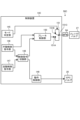
- FIG. 11 is a block diagram showing a part of a control system 50B of a hydraulic excavator 1 according to another embodiment.
- the brake control unit 150 in the automatic mode, it is determined whether or not the automatic operation command input to the brake control unit 150 satisfies the brake actuation condition. That is, in step S5 described with reference to FIG. 9, it is determined whether or not the neutral state of the automatic operation command has elapsed for 5 seconds.
- the brake control unit 150 may control the swing parking brake 28 based on the pilot pressure applied to the main valve 21 by the EPC valve 20 (control valve).
- the brake control unit 150 may determine whether or not the brake actuation condition is satisfied based on the pilot pressure.
- the control device 14B of the control system 50B has a manual control command unit 146, an automatic control command unit 147, a control command switching unit 148, an operation control unit 149, and a brake control unit 150, similar to the control device 14 described in the above embodiment.
- the pilot pressure applied to the main valve 21 by the EPC valve 20 is detected by the pressure sensor 30.
- the brake control unit 150 activates the swing parking brake 28 when the left operation lever 7A has been in the neutral state for 5 seconds.
- the automatic control command unit 147 controls the EPC valve 20 so that the pilot pressure applied to the main valve 21 becomes equal to or greater than a predetermined value.
- the brake control unit 150 activates the swing parking brake 28.
- FIG. 12 is a block diagram showing a part of a control system 50C of a hydraulic excavator 1 according to another embodiment.
- the control device 14C of the control system 50C has a mode determination unit 145, a manual control command unit 146, an automatic control command unit 147, a control command switching unit 148, an operation control unit 149, and a brake control unit 150, similar to the control device 14 described in the above embodiment.
- the control device 14C also has a switch unit 151.
- the switch unit 151 operates based on the operation mode determined by the mode determination unit 145.
- the switch unit 151 In the manual mode, the switch unit 151 operates so that a manual control command generated based on an operation signal from the left operation lever 7A is transmitted to the swing parking brake 28, and in the automatic mode, a release command for releasing the operation of the swing parking brake 28 is transmitted to the swing parking brake 28.
- the switch unit 151 has a brake command input unit 151A, a release command input unit 151B, and an output unit 151C.
- the brake command input unit 151A is connected to the brake control unit 150.
- the switch unit 151 switches between a state in which the brake command input unit 151A is connected to the output unit 151C and a state in which the release command input unit 151B is connected to the output unit 151C.
- the brake command input unit 151A is connected to the output unit 151C.
- the brake control unit 150 outputs a manual control command to the solenoid valve 27 via the switch unit 151 so that the swing parking brake 28 is activated when the neutral state of the left operation lever 7A has elapsed for 5 seconds.
- the release command input unit 151B is connected to the output unit 151C.
- a release command to release the operation of the swing parking brake 28 is output to the solenoid valve 27. That is, in the automatic mode, the swing parking brake 28 is not activated.
- the rotating body 4 can perform hoist rotation or down rotation based on an automatic control command from the automatic control command unit 147.
- a release signal to release the swing parking brake 28 may be output to the solenoid valve 27 regardless of the operation state of the swing lock switch 9A.
- the excavation target position 16R, the soil discharge target position 17R, and the intermediate target position 18R are set as multiple target positions for the bucket 5C in the automatic mode.
- the intermediate target position 18R does not have to be set.
- the target position is set by operating the teaching switch 9C.
- the positions of the excavation target 16 and the soil discharge target 17 may be detected by a three-dimensional sensor such as a laser sensor (LiDAR: Light Detection and Ranging) or a stereo camera, and the target position may be set based on the position detected by the three-dimensional sensor.
- the target trajectory of the bucket 5C may be set.
- the orientation of the rotating body 4 is calculated based on the detection data of the first position sensor 11A and the detection data of the second position sensor 11B.
- An angle sensor capable of detecting the rotation angle of the rotating body 4 such as an encoder or potentiometer, may be mounted on the hydraulic excavator 1, and the orientation of the rotating body 4 may be calculated based on the detection data of the angle sensor.
- the swing lock switch 9A only needs to be located in the cab 2, and can be installed at any position in the cab 2.
- a swing lock input device that is operated to activate the swing parking brake 28 may be provided on the in-vehicle monitor 8.
- the swing lock input device may be, for example, a touch panel.
- the swing lock input device may also be provided on a tablet terminal.
- the swing lock input device may also be provided outside the cab 2.
- the swing lock input device may be located in a remote location of the hydraulic excavator 1, and the swing parking brake 28 may be remotely operated.
- each of the position calculation unit 141, teaching unit 142, target position memory unit 143, automatic permission unit 144, mode determination unit 145, manual control command unit 146, automatic control command unit 147, control command switching unit 148, operation control unit 149, brake control unit 150, and switch unit 151 may be configured as separate hardware.
- the work machine 1 is a hydraulic excavator having a running body 3, a rotating body 4, and a working implement 5.
- the work machine 1 only needs to have a rotating body 4.
- the rotating body 4 may be rotated by an electric rotating motor.
- the work machine 1 may be a hybrid shovel or an electric shovel.
- the work machine 1 may be a rope shovel.
- the operation mode for the excavation operation and the operation mode for the soil discharge operation are manual modes.
- the operation mode for the excavation operation and the operation mode for the soil discharge operation may be automatic modes.
- the operation mode of the hoist rotation operation and the operation mode of the down rotation operation are automatic modes.
- One of the operation modes of the hoist rotation operation and the down rotation operation may be the automatic mode, and the other operation mode may be the manual mode.
- the intermediate target position 18R does not need to be set.
- the automatic permission switch 9B may be omitted.
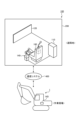
- FIG. 13 is a schematic diagram showing a remote control system 100 for a work machine 1 according to another embodiment.
- the remote control system 100 remotely controls the work machine 1 working at a work site.
- the remote control system 100 includes the above-described control system (50, 50B, 50C). At least a part of the remote control system 100 is disposed in a remote control room 200 outside the work machine 1.
- the remote control room 200 is installed in a remote location away from the work site.
- the remote operation system 100 includes a remote operation device 140, a display device 120, and a controller 110.
- the remote operation device 140 is arranged in a remote operation room 200.
- the remote operation device 140 is operated by an operator in the remote operation room 200.
- the operator can operate the remote operation device 140 while seated in the driver's seat 160.
- the remote operation device 140 When operated by the operator, the remote operation device 140 generates an operation signal that operates the work machine 5 and the rotating body 4.
- the display device 120 is placed in the remote control room 200.
- the display device 120 displays an image of the work site.
- An operator in the remote control room 200 can visually confirm the situation at the work site via the display device 120.
- the operator operates the remote control device 140 while viewing the image of the work site displayed on the display device 120.
- the work machine 1 is remotely controlled by the remote control device 140.
- the controller 110 is disposed in the remote control room 200.
- the controller 110 includes a computer system.
- the work machine 1 is equipped with a control device 14D.
- the control device 14D includes a computer system.
- the controller 110 and the control device 14D communicate via a communication system 400.
- Examples of the communication system 400 include the Internet, a local area network (LAN), a mobile phone communication network, or a satellite communication network.
- the communication system 400 may include a relay station that relays the data to be communicated.
- a swing lock switch and a lock lever are arranged in the remote control room 200.
- ON/OFF signals of the swing lock switch and the lock lever are transmitted to the work machine 1, and the control device 14D of the work machine 1 operates based on the transmitted signals. Note that it is also possible to remotely control the work machine 1 after getting on board and operating the switches.
Landscapes
- Engineering & Computer Science (AREA)
- Mining & Mineral Resources (AREA)
- Civil Engineering (AREA)
- General Engineering & Computer Science (AREA)
- Structural Engineering (AREA)
- Mechanical Engineering (AREA)
- Life Sciences & Earth Sciences (AREA)
- General Life Sciences & Earth Sciences (AREA)
- Paleontology (AREA)
- Operation Control Of Excavators (AREA)
Abstract
Description
図1は、実施形態に係る作業機械1を示す斜視図である。図2は、実施形態に係る作業機械1を示す模式図である。図3は、実施形態に係る作業機械1の運転室2を示す図である。
図4及び図5のそれぞれは、実施形態に係る油圧ショベル1の動作を説明するための図である。実施形態において、油圧ショベル1は、掘削動作と、ホイスト旋回動作と、排土動作と、ダウン旋回動作とを繰り返す。掘削動作とは、旋回体4の前面が掘削対象16に正対した状態で、バケット5Cで掘削対象16を掘削する動作をいう。ホイスト旋回動作とは、作業機5を上げる動作と旋回体4を旋回させる動作とがともに行われる動作をいう。ホイスト旋回動作は、ブーム5Aの上げ動作と旋回体4の旋回動作とがともに行われる動作を含む。例えば、ホイスト旋回動作とは、バケット5Cで掘削対象16を掘削した後、旋回体4の前面が排土対象17に正対し、掘削物を保持したバケット5Cが排土対象17の上方に配置されるように、作業機5を動作させ、旋回体4を旋回させる動作をいう。排土動作とは、旋回体4の前面が排土対象17に正対した状態で、バケット5Cに保持されている掘削物を排土対象17に排出する動作をいう。ダウン旋回動作とは、作業機5を下げる動作と旋回体4を旋回させる動作とがともに行われる動作をいう。ダウン旋回動作は、ブーム5Aの下げ動作と旋回体4の旋回動作とがともに行われる動作を含む。例えば、ダウン旋回動作とは、バケット5Cから排土対象17に掘削物を排出した後、旋回体4の前面が掘削対象16に正対し、バケット5Cが掘削対象16に配置されるように、作業機5を動作させ、旋回体4を旋回させる動作をいう。排土対象17として、ダンプトラックのベッセルが例示される。なお、排土対象17の他の例として、ホッパ、自走式土質改良機、及びベルトコンベア等が挙げられる。
図6は、実施形態に係る掘削目標位置16R及び排土目標位置17Rを設定するティーチング処理を説明するための図である。掘削目標位置16R及び排土目標位置17Rは、ティーチング処理により設定される。
図7は、実施形態に係る作業機械1の制御システム50を示すブロック図である。油圧ショベル1は、制御システム50を備える。制御システム50は、操作装置7と、入力装置9と、ロックレバー10と、位置センサ11と、慣性センサ12と、姿勢センサ13と、制御装置14とを有する。制御装置14は、油圧ショベル1を制御する。制御装置14は、コンピュータシステムを含む。操作装置7、入力装置9、ロックレバー10、位置センサ11、慣性センサ12、及び姿勢センサ13のそれぞれは、制御装置14に接続される。
図8は、実施形態に係る自動制御の可否判定及び動作モードの切り換えを説明するための図である。手動モードにおいて自動制御が不許可の状態で、第1遷移条件が満たされない場合、自動制御が不許可される。手動モードにおいて自動制御が不許可の状態で、第1遷移条件が満たされた場合、自動制御が許可される。第1遷移条件は、旋回ロックスイッチ9Aが操作されていないことを含む。自動許可部144は、手動モードにおいて、旋回ロックスイッチ9Aの操作により旋回駐車ブレーキ28が作動している場合、自動制御を不許可する。自動許可部144は、手動モードにおいて、旋回ロックスイッチ9Aの非操作により旋回駐車ブレーキ28が作動していない場合、自動制御を許可する。
図9は、実施形態に係る油圧ショベル1の制御方法を示すフローチャートである。手動モードにおいて、自動許可部144は、図8を参照して説明した第1遷移条件を満たすか否かを判定する。実施形態において、自動許可部144は、旋回ロックスイッチ9Aの操作状態に基づいて、自動制御の可否を判定する(ステップS1)。
図10は、実施形態に係るコンピュータシステム1000を示すブロック図である。上述の制御装置14は、コンピュータシステム1000を含む。コンピュータシステム1000は、CPU(Central Processing Unit)のようなプロセッサ1001と、ROM(Read Only Memory)のような不揮発性メモリ及びRAM(Random Access Memory)のような揮発性メモリを含むメインメモリ1002と、ストレージ1003と、入出力回路を含むインターフェース1004とを有する。上述の制御装置14の機能は、コンピュータプログラムとしてストレージ1003に記憶されている。プロセッサ1001は、コンピュータプログラムをストレージ1003から読み出してメインメモリ1002に展開し、プログラムに従って上述の処理を実行する。なお、コンピュータプログラムは、ネットワークを介してコンピュータシステム1000に配信されてもよい。
以上説明したように、実施形態によれば、油圧ショベル1は、旋回体4と、旋回体4に取り付けられる作業機5と、旋回体4の旋回を停止可能な旋回駐車ブレーキ28と、旋回駐車ブレーキ28を作動させるために操作される旋回ロックスイッチ9A(旋回ロック入力装置)と、旋回体4及び作業機5を自動制御する自動制御指令を出力する自動制御指令部147と、旋回ロックスイッチ9Aの操作状態に基づいて、旋回体4及び作業機5の自動制御の可否を判定する自動許可部144と、を備える。
図11は、他の実施形態に係る油圧ショベル1の制御システム50Bの一部を示すブロック図である。上述の実施形態においては、自動モードにおいて、ブレーキ制御部150に入力される自動操作指令がブレーキ作動条件を満たすか否かを判定することとした。すなわち、図9を参照して説明したステップS5において、自動操作指令の中立状態が5秒を経過するか否かを判定することとした。図11に示すように、ブレーキ制御部150は、自動モードにおいて、EPCバルブ20(制御バルブ)によってメインバルブ21に与えられるパイロット圧に基づいて、旋回駐車ブレーキ28を制御してもよい。ブレーキ制御部150は、自動モードにおいて、パイロット圧に基づいて、ブレーキ作動条件が満たされるか否かを判定してもよい。制御システム50Bの制御装置14Bは、上述の実施形態において説明した制御装置14と同様、手動制御指令部146、自動制御指令部147、制御指令切換部148、動作制御部149、及びブレーキ制御部150を有する。EPCバルブ20によってメインバルブ21に与えられるパイロット圧は、圧力センサ30により検出される。手動モードにおいて、ブレーキ制御部150は、左操作レバー7Aの中立状態が5秒を経過したときに、旋回駐車ブレーキ28を作動させる。自動モードにおいて旋回体4を旋回させる場合、自動制御指令部147は、メインバルブ21に与えられるパイロット圧が所定値以上になるようにEPCバルブ20を制御する。自動モードにおいて、旋回体4を旋回させるパイロット圧が検出されない状態が5秒を経過した場合、すなわち、圧力センサ30によって検出されるパイロット圧が所定値未満である状態が5秒を経過した場合、ブレーキ制御部150は、旋回駐車ブレーキ28を作動させる。
Claims (11)
- 旋回体と、
前記旋回体に取り付けられる作業機と、
前記旋回体の旋回を停止可能な旋回駐車ブレーキと、
前記旋回駐車ブレーキを作動させるために操作される旋回ロック入力装置と、
前記旋回体及び前記作業機を自動制御する自動制御指令を出力する自動制御指令部と、
前記旋回ロック入力装置の操作状態に基づいて、前記自動制御の可否を判定する自動許可部と、を備える、
作業機械の制御システム。 - 前記自動許可部は、前記旋回ロック入力装置が操作されている状態の場合、前記自動制御を不許可とする、
請求項1に記載の作業機械の制御システム。 - 前記自動許可部は、前記旋回ロック入力装置が操作されていない状態の場合、前記自動制御を許可する、
請求項1に記載の作業機械の制御システム。 - 前記自動許可部は、前記旋回ロック入力装置が操作されていない状態の場合、前記自動制御を許可する
請求項2に記載の作業機械の制御システム。 - 前記自動制御を開始するために操作される自動開始入力装置を備え、
前記自動制御指令部は、前記自動制御が許可された状態で、前記自動開始入力装置が操作された場合、前記自動制御指令を出力する、
請求項4に記載の作業機械の制御システム。 - 掘削対象に設定された掘削目標位置を記憶する目標位置記憶部を備え、
前記自動制御指令部は、前記作業機のバケットが前記掘削目標位置に移動するように、前記自動制御指令を出力する、
請求項5に記載の作業機械の制御システム。 - 排土対象に設定された排土目標位置を記憶する目標位置記憶部を備え、
前記自動制御指令部は、前記作業機のバケットが前記排土目標位置に移動するように、前記自動制御指令を出力する、
請求項5に記載の作業機械の制御システム。 - 前記旋回体及び前記作業機のそれぞれを動作不可能にするために操作される動作ロック操作装置を備え、
前記自動許可部は、前記旋回ロック入力装置の操作状態及び前記動作ロック操作装置の操作状態に基づいて、前記自動制御の可否を判定する、
請求項1に記載の作業機械の制御システム。 - 請求項1に記載の作業機械の制御システムを備える、
作業機械。 - 旋回体の旋回を停止可能な旋回駐車ブレーキを作動するために操作される旋回ロック入力装置の操作状態を取得することと、
前記旋回ロック入力装置の操作状態に基づいて、前記旋回体及び前記旋回体に取り付けられる作業機の自動制御の可否を判定することと、を含む、
作業機械の制御方法。 - 請求項1に記載の作業機械の制御システムと、
前記作業機械の外部に配置され、前記作業機械を遠隔操作する遠隔操作装置と、を備える、
作業機械の遠隔操作システム。
Priority Applications (4)
| Application Number | Priority Date | Filing Date | Title |
|---|---|---|---|
| US19/149,595 US20260226704A1 (en) | 2023-02-24 | 2024-01-12 | Control system for work machine, work machine, control method for work machine, and remote operation system for work machine |
| KR1020257025593A KR20250129089A (ko) | 2023-02-24 | 2024-01-12 | 작업 기계의 제어 시스템, 작업 기계, 작업 기계의 제어 방법, 및 작업 기계의 원격 조작 시스템 |
| CN202480012804.5A CN120752401A (zh) | 2023-02-24 | 2024-01-12 | 作业机械的控制系统、作业机械、作业机械的控制方法以及作业机械的远程操作系统 |
| DE112024000383.4T DE112024000383T9 (de) | 2023-02-24 | 2024-01-12 | Steuerungssystem für arbeitsmaschine, arbeitsmaschine, steuerungsverfahren für arbeitsmaschine und fernbedienungssystem für arbeitsmaschine |
Applications Claiming Priority (2)
| Application Number | Priority Date | Filing Date | Title |
|---|---|---|---|
| JP2023026914A JP2024120246A (ja) | 2023-02-24 | 2023-02-24 | 作業機械の制御システム、作業機械、作業機械の制御方法、及び作業機械の遠隔操作システム |
| JP2023-026914 | 2023-02-24 |
Publications (1)
| Publication Number | Publication Date |
|---|---|
| WO2024176643A1 true WO2024176643A1 (ja) | 2024-08-29 |
Family
ID=92500897
Family Applications (1)
| Application Number | Title | Priority Date | Filing Date |
|---|---|---|---|
| PCT/JP2024/000540 Ceased WO2024176643A1 (ja) | 2023-02-24 | 2024-01-12 | 作業機械の制御システム、作業機械、作業機械の制御方法、及び作業機械の遠隔操作システム |
Country Status (6)
| Country | Link |
|---|---|
| US (1) | US20260226704A1 (ja) |
| JP (1) | JP2024120246A (ja) |
| KR (1) | KR20250129089A (ja) |
| CN (1) | CN120752401A (ja) |
| DE (1) | DE112024000383T9 (ja) |
| WO (1) | WO2024176643A1 (ja) |
Citations (5)
| Publication number | Priority date | Publication date | Assignee | Title |
|---|---|---|---|---|
| JPH0674656U (ja) * | 1991-05-22 | 1994-10-21 | 住友建機株式会社 | 油圧式建設機械の旋回ロック回路 |
| JP2010112096A (ja) * | 2008-11-07 | 2010-05-20 | Hitachi Constr Mach Co Ltd | 建設機械の旋回ロック装置 |
| JP2014101695A (ja) * | 2012-11-20 | 2014-06-05 | Komatsu Ltd | 作業機械および作業機械の作業量計測方法 |
| JP2021011694A (ja) * | 2019-07-04 | 2021-02-04 | 株式会社小松製作所 | 作業機械および作業機械の制御方法 |
| JP2022084335A (ja) * | 2020-11-26 | 2022-06-07 | 株式会社小松製作所 | 作業機械 |
-
2023
- 2023-02-24 JP JP2023026914A patent/JP2024120246A/ja active Pending
-
2024
- 2024-01-12 WO PCT/JP2024/000540 patent/WO2024176643A1/ja not_active Ceased
- 2024-01-12 US US19/149,595 patent/US20260226704A1/en active Pending
- 2024-01-12 KR KR1020257025593A patent/KR20250129089A/ko active Pending
- 2024-01-12 DE DE112024000383.4T patent/DE112024000383T9/de active Active
- 2024-01-12 CN CN202480012804.5A patent/CN120752401A/zh active Pending
Patent Citations (5)
| Publication number | Priority date | Publication date | Assignee | Title |
|---|---|---|---|---|
| JPH0674656U (ja) * | 1991-05-22 | 1994-10-21 | 住友建機株式会社 | 油圧式建設機械の旋回ロック回路 |
| JP2010112096A (ja) * | 2008-11-07 | 2010-05-20 | Hitachi Constr Mach Co Ltd | 建設機械の旋回ロック装置 |
| JP2014101695A (ja) * | 2012-11-20 | 2014-06-05 | Komatsu Ltd | 作業機械および作業機械の作業量計測方法 |
| JP2021011694A (ja) * | 2019-07-04 | 2021-02-04 | 株式会社小松製作所 | 作業機械および作業機械の制御方法 |
| JP2022084335A (ja) * | 2020-11-26 | 2022-06-07 | 株式会社小松製作所 | 作業機械 |
Also Published As
| Publication number | Publication date |
|---|---|
| US20260226704A1 (en) | 2026-08-06 |
| JP2024120246A (ja) | 2024-09-05 |
| DE112024000383T5 (de) | 2025-10-23 |
| DE112024000383T9 (de) | 2025-12-18 |
| CN120752401A (zh) | 2025-10-03 |
| KR20250129089A (ko) | 2025-08-28 |
Similar Documents
| Publication | Publication Date | Title |
|---|---|---|
| JP7490639B2 (ja) | ショベル | |
| JP2024169569A (ja) | ショベル | |
| CN113544336B (zh) | 作业机械 | |
| JP2020165259A (ja) | ショベル | |
| KR102606721B1 (ko) | 작업 기계, 작업 기계를 포함하는 시스템, 및 작업 기계의 제어 방법 | |
| JP2022137769A (ja) | ショベル、情報処理装置 | |
| JP7420619B2 (ja) | ショベル | |
| JP7420618B2 (ja) | ショベル | |
| JP2024120246A (ja) | 作業機械の制御システム、作業機械、作業機械の制御方法、及び作業機械の遠隔操作システム | |
| WO2024176777A1 (ja) | 作業機械の制御システム及び作業機械の制御方法 | |
| CN118110221A (zh) | 挖土机的控制装置及挖土机 | |
| JP2020165256A (ja) | ショベル | |
| JP2024061373A (ja) | 作業機械の制御装置 | |
| JP2024127611A (ja) | 作業機械 | |
| JP7395403B2 (ja) | 検出装置及びショベル | |
| JP2025018759A (ja) | 作業機械の制御システム、作業機械、作業機械の制御方法、及び作業機械の遠隔操作システム | |
| JP2025101389A (ja) | ショベル及びショベルの制御装置 | |
| JP2023151600A (ja) | ショベル及びショベルの制御システム | |
| WO2024157918A1 (ja) | 積込機械の制御装置、積込機械の制御方法および積込機械の制御システム | |
| JP2025101391A (ja) | ショベル | |
| JP2026032350A (ja) | 作業機械の自動旋回制御システム、作業機械、および作業機械の自動旋回制御方法 | |
| WO2024202978A1 (ja) | 制御装置、制御方法および作業機械 | |
| JP2024113561A (ja) | ショベル | |
| WO2025028107A1 (ja) | 作業機械の制御システム、作業機械の制御方法および作業機械の遠隔操作システム | |
| WO2024225453A1 (ja) | ショベル、遠隔操作システム、及び、制御方法 |
Legal Events
| Date | Code | Title | Description |
|---|---|---|---|
| 121 | Ep: the epo has been informed by wipo that ep was designated in this application |
Ref document number: 24759951 Country of ref document: EP Kind code of ref document: A1 |
|
| ENP | Entry into the national phase |
Ref document number: 1020257025593 Country of ref document: KR Free format text: ST27 STATUS EVENT CODE: A-0-1-A10-A15-NAP-PA0105 (AS PROVIDED BY THE NATIONAL OFFICE) |
|
| WWE | Wipo information: entry into national phase |
Ref document number: 112024000383 Country of ref document: DE |
|
| WWE | Wipo information: entry into national phase |
Ref document number: 202480012804.5 Country of ref document: CN |
|
| WWP | Wipo information: published in national office |
Ref document number: 1020257025593 Country of ref document: KR |
|
| WWP | Wipo information: published in national office |
Ref document number: 202480012804.5 Country of ref document: CN |
|
| WWP | Wipo information: published in national office |
Ref document number: 112024000383 Country of ref document: DE |
|
| 122 | Ep: pct application non-entry in european phase |
Ref document number: 24759951 Country of ref document: EP Kind code of ref document: A1 |