WO2024176552A1 - 基板処理装置および基板処理方法 - Google Patents
基板処理装置および基板処理方法 Download PDFInfo
- Publication number
- WO2024176552A1 WO2024176552A1 PCT/JP2023/042345 JP2023042345W WO2024176552A1 WO 2024176552 A1 WO2024176552 A1 WO 2024176552A1 JP 2023042345 W JP2023042345 W JP 2023042345W WO 2024176552 A1 WO2024176552 A1 WO 2024176552A1
- Authority
- WO
- WIPO (PCT)
- Prior art keywords
- substrate
- action
- chuck
- plating
- fluid
- Prior art date
- Legal status (The legal status is an assumption and is not a legal conclusion. Google has not performed a legal analysis and makes no representation as to the accuracy of the status listed.)
- Ceased
Links
Images






Classifications
-
- C—CHEMISTRY; METALLURGY
- C25—ELECTROLYTIC OR ELECTROPHORETIC PROCESSES; APPARATUS THEREFOR
- C25D—PROCESSES FOR THE ELECTROLYTIC OR ELECTROPHORETIC PRODUCTION OF COATINGS; ELECTROFORMING; APPARATUS THEREFOR
- C25D17/00—Constructional parts, or assemblies thereof, of cells for electrolytic coating
-
- C—CHEMISTRY; METALLURGY
- C25—ELECTROLYTIC OR ELECTROPHORETIC PROCESSES; APPARATUS THEREFOR
- C25D—PROCESSES FOR THE ELECTROLYTIC OR ELECTROPHORETIC PRODUCTION OF COATINGS; ELECTROFORMING; APPARATUS THEREFOR
- C25D17/00—Constructional parts, or assemblies thereof, of cells for electrolytic coating
- C25D17/06—Suspending or supporting devices for articles to be coated
- C25D17/08—Supporting racks, i.e. not for suspending
-
- C—CHEMISTRY; METALLURGY
- C25—ELECTROLYTIC OR ELECTROPHORETIC PROCESSES; APPARATUS THEREFOR
- C25D—PROCESSES FOR THE ELECTROLYTIC OR ELECTROPHORETIC PRODUCTION OF COATINGS; ELECTROFORMING; APPARATUS THEREFOR
- C25D21/00—Processes for servicing or operating cells for electrolytic coating
- C25D21/04—Removal of gases or vapours ; Gas or pressure control
Definitions
- This invention relates to a substrate processing apparatus and a substrate processing method that use a fluid to perform a predetermined operation on a substrate, such as a printed wiring board or a glass substrate.
- a substrate such as a printed wiring board or a glass substrate.
- using a fluid here is not limited to a direct application of a fluid to a substrate, but is a comprehensive concept that refers to any operation in which a fluid is involved in some way.
- Patent Document 1 describes a device that performs plating processing by immersing a substrate in a plating solution.
- a plating device one end of the substrate that is transported to a processing tank that stores the plating solution is held by a clamp equipped with a cathode electrode. The clamp moves, and the substrate is plated while being transported within the processing tank.
- the peripheral edge of the substrate is gripped by a ring-shaped substrate holder that is provided with a cathode electrode and has an opening in the center.
- the substrate holder is then suspended and immersed in a treatment tank that stores plating solution, thereby treating the substrate with the plating solution.
- a processing operation using a fluid may be performed on the substrate.
- a fluid such as a purge gas
- fluid piping tends to be thicker and less flexible. For this reason, there is a demand for technology that can ensure a flow path that can reliably circulate the fluid required for operation without impeding the movement of the action part, even when the action part moves significantly.
- technology has not yet been established.
- This invention has been made in consideration of the above problems, and aims to provide a technology for a substrate processing apparatus and substrate processing method in which operations are performed using a fluid, which can reliably form a flow path for the fluid required for operation without impeding the movement, even in a configuration in which the action part moves significantly.
- One aspect of the present invention is a substrate processing apparatus including an action unit positioned at a first position and performing a predetermined operation on a substrate using a fluid, a movement mechanism for moving the action unit between the first position and a second position that are different from each other, and a flow path forming unit that is connected to the action unit positioned at the first position and forms a flow path through which the fluid flows.
- the flow path forming unit has a moving pipe that moves integrally with the action unit by the movement mechanism, a fixed pipe that is connected to a distribution source of the fluid and does not follow the movement of the action unit by the movement mechanism, and a connection mechanism that connects the moving pipe and the fixed pipe when the action unit is positioned at the first position and releases the connection when the action unit moves away from the first position.
- Another aspect of the present invention is a substrate processing method including the steps of moving an action part, which performs a predetermined operation on a substrate, between a first position and a second position that are different from each other, by a moving mechanism, and the action part positioned at the first position performing the predetermined operation using a fluid.
- the action part is provided with a moving pipe that moves integrally with the action part by the moving mechanism, and a fixed pipe that is connected to a circulation source of the fluid and does not follow the movement of the action part by the moving mechanism.
- a connection mechanism connects the moving pipe and the fixed pipe, and when the action part moves away from the first position, the connection mechanism releases the connection.
- the piping that constitutes the fluid flow path is divided into a movable piping and a fixed piping.
- the movable piping moves in conjunction with the movement of the action part, while the fixed piping is connected to a fluid distribution source and does not follow the movement of the action part. This prevents the piping from impeding the movement of the action part.
- the action part is in a first position where a fluid flow path is required for the action part to operate, the movable piping and the fixed piping are connected by a connection mechanism, thereby forming a fluid flow path. As a result, it becomes possible to realize an operation using a fluid by the action part.
- the piping that serves as the fluid flow path is not always connected, but rather, when the fluid is in a first position required for operation, a moving piping that moves integrally with the action part is temporarily connected to a fixed piping that does not move with the action part and is connected to a fluid flow source. Therefore, the piping does not impede the movement of the action part, and the necessary fluid flow path can be reliably formed during operation.
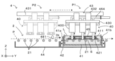
- FIG. 1 is a diagram showing a schematic configuration of a plating apparatus according to a first embodiment of the present invention
- 1 is a diagram showing a schematic configuration of a plating apparatus according to a first embodiment of the present invention
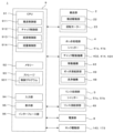
- FIG. 2 is a block diagram showing the electrical configuration of the plating apparatus.
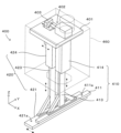
- FIG. 2 is a diagram showing a schematic configuration of a chuck mechanism.
- FIG. 2 is a diagram showing a schematic configuration of a chuck mechanism.
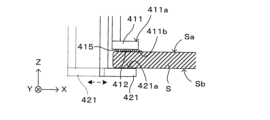
- FIG. 4 is a diagram showing a schematic side view of a main part of a chuck mechanism.
- FIG. 4 is a diagram showing a schematic side view of a main part of a chuck mechanism.
- 1 is a flowchart showing a plating process.
- FIG. 2 is a diagram illustrating the movement of each part during processing.
- FIG. 2 is a diagram illustrating the movement of each part during processing.
- FIG. 2 is a diagram illustrating the movement of each part during processing.
- FIG. 2 is a diagram illustrating the movement of each part during processing.
- FIG. 2 is a diagram illustrating the movement of each part during processing.
- 4A to 4C are three orthographic views showing the structure of the cover.
- 11A and 11B are diagrams illustrating airflow control in the cover.
- FIG. 4 is a diagram illustrating a joint mechanism in the exhaust system.
- FIG. 4 is a diagram illustrating a joint mechanism in the air supply system.
- FIG. 1 is a diagram showing a schematic configuration of a plating apparatus according to a second embodiment of the present invention.
- FIG. 1A and 1B are diagrams showing the schematic configuration of a plating apparatus according to a first embodiment of the present invention.
- FIG. 2 is a block diagram showing the electrical configuration of the plating apparatus.
- the plating apparatus 1 is an apparatus for forming a metal (e.g., gold) film by electrolytic plating on at least one main surface of various substrates S, such as semiconductor substrates, printed wiring substrates, and glass substrates (hereinafter simply referred to as "substrates").
- substrates S such as semiconductor substrates, printed wiring substrates, and glass substrates (hereinafter simply referred to as "substrates").
- substrates S such as semiconductor substrates, printed wiring substrates, and glass substrates
- FIG. 1A an XYZ Cartesian coordinate system is defined as shown in FIG. 1A.
- FIG. 1A is a diagram showing a side view of the plating apparatus 1, and the direction that is horizontal and perpendicular to the paper surface of FIG.
- FIG. 1A is the X direction, and the direction that is horizontal and perpendicular to the X direction and parallel to the paper surface of FIG. 1A is the Y direction.
- the vertical direction is the Z direction.
- the dashed arrows attached near each member indicate the movement direction of the member.
- the plating apparatus 1 has a structure in which each part described below is assembled to a housing 10 formed by combining multiple frame members. Note that in FIG. 1A and the following figures, the description of some components may be omitted as appropriate to avoid cluttering the drawings. Specifically, components that contribute relatively little to the establishment of the invention and whose structure is such that appropriate publicly known technology can be applied and no special explanation is considered to be required may be omitted from the illustration. For example, a holding mechanism for holding parts, a cover for covering the parts, and a mechanism for attaching them to the housing 10 fall into this category.
- the plating device 1 is provided with a transport section 2 that transports the substrate S along the Y direction.
- the transport section 2 includes a plurality of transport rollers 21 arranged along the Y direction.
- the transport rollers 21 are supported by a support mechanism (not shown) so that they can rotate freely about the X direction as their axial direction.
- a rotary motor 23 is coupled to the rotation shaft of the transport roller 21.
- the transport drive section 22 rotates the rotary motor 23 in response to a control command from the control section 9 (described later), so that the transport section 2 transports the substrate S in the Y direction in a horizontal position.
- the rectangular substrate S is transported with one of the four sides at the front.
- the transport direction of the substrate S is represented by the symbol Dt.
- the substrate S is transported in a straight line in the Y direction while maintaining a horizontal position. Therefore, the transport direction Dt is equal to the Y direction.
- some of the transport rollers 21 may be driven rollers to which no drive source is connected.
- the plating apparatus 1 further includes an entrance section 3, a plating processing section 4, a rinsing processing section 5, an unloading section 6, a power supply section 7, and a control section 9.
- the entrance section 3, the plating processing section 4, the rinsing processing section 5, and the unloading section 6 are arranged in this order along the transport direction Dt (Y direction) of the substrate by the transport section 2. That is, in this plating apparatus 1, the substrate S is subjected to the necessary processing in each of the above-mentioned processing sections while being transported in the Y direction by the transport section 2.
- the loading section 3 receives and temporarily holds the unprocessed substrate S transported from the outside, and supplies the substrate S to the plating processing section 4 at the required timing.
- the plating processing section 4 is the processing main body that carries out the plating method according to the present invention, and performs plating processing by immersing the substrate S in a plating solution. The configuration of the plating processing section 4 will be described in detail later.
- the rinsing treatment section 5 comprises a rinsing tank 51, a tray 52, and a rinsing liquid supply/discharge section 59.
- the rinsing tank 51 has an internal space of a necessary and sufficient size to accommodate the substrate S, and nozzles (not shown) are disposed in the internal space for spraying rinsing liquid toward the upper and lower surfaces of the substrate S.
- An opening is provided on the Y-direction side surface of the rinsing tank 51 at a portion that overlaps with the transport path P.
- Shutters 51a and 51b are provided for the opening so as to be able to be opened and closed freely.
- the tray 52 is disposed below the rinse tank 51 and receives the rinse liquid spilled from the rinse tank 51.
- the rinse liquid supply/discharge unit 59 supplies rinse liquid to the nozzles in the rinse tank 51 as necessary, and also discharges rinse liquid from the rinse tank 51.
- the rinse processing unit 5 performs a rinse process on the substrate S immersed in the plating liquid in the plating processing unit 4. Water, for example, is used as the rinse liquid.
- the discharge unit 6 temporarily holds the substrate S sent out from the rinse processing unit 5 after the rinse process until it is removed to a post-processing step by an external transport device.
- the power supply unit 7 supplies the necessary power to each part of the apparatus.
- the control unit 9 controls each part of the apparatus configured as described above, and causes the plating apparatus 1 to perform predetermined processing.
- the hardware configuration of the control unit 9 may be the same as that of a general computer device, for example.
- the control unit 9 may include a CPU (Central Processing Unit) 91, memory 92, storage 93, input unit 94, display unit 95, interface unit 96, etc.
- CPU Central Processing Unit
- Memory 92 temporarily stores various data generated during processing.
- Storage 93 stores various data and control programs 931 on a long-term basis.
- Input unit 94 and display unit 95 perform user interface functions.
- Interface unit 96 handles communication with external devices, etc.
- the CPU 91 reads and executes a control program 931 pre-stored in the storage 93, and based on this, controls each part of the device to perform a predetermined operation, thereby realizing various operations described below.
- the CPU 91 realizes in software functional blocks such as a transport control unit 911 that controls the operation of the transport unit 2, a chuck control unit 912 that controls the operation of the chuck unit 40 described below, a supply and discharge control unit 913 that controls the supply sources of various fluids and manages their supply and discharge, and a flow control unit 914 that controls valves on the piping to adjust the flow rate of the circulating fluid.
- these functional blocks may be configured as dedicated hardware, for example.
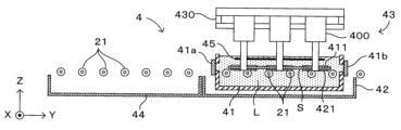
- FIG. 1B is a front view showing the schematic configuration of the plating processing section.
- the plating processing section 4 includes a plating tank 41, vats 42 and 44, a chuck section 40, a cleaning mechanism 48, and a plating liquid supply/discharge section 49.
- the plating tank 41 is capable of storing plating liquid in an internal space having a size sufficient to accommodate the substrate S.
- the vat 42 is disposed below the plating tank 41 and receives spilled plating liquid.
- the chuck section 40 is disposed above the plating tank 41 and holds the substrate S to be plated.
- the vat 44 is disposed adjacent to the vat 42 below the plating tank 41 on the (-Y) side.
- the cleaning mechanism 48 cleans the chuck section 40 with an appropriate cleaning liquid (e.g., water).
- the cleaning mechanism 48 includes a cleaning nozzle 481 provided in the vat 44 and a cleaning liquid supply/discharge section 482 that supplies cleaning liquid to the cleaning nozzle 481.
- the plating solution supply/discharge unit 49 supplies plating solution to the plating tank 41 and discharges plating solution from the plating tank 41 in response to control commands from the supply/discharge control unit 913 of the control unit 9.
- openings are provided on the (-Y) side and (+Y) side of plating tank 41 at portions that overlap with transport path P.
- Shutters 41a, 41b that can be opened and closed are provided at these openings.
- substrate S transported along transport path P by transport unit 2 can pass through the openings provided on the sides of plating tank 41. This makes it possible to transport unprocessed substrates S into plating tank 41 and to transport processed substrates S out of plating tank 41.
- the opening on the side of the plating tank 41 is closed.
- the transport path P for the substrate S is blocked, but the plating solution can be stored inside the plating tank 41 beyond the height of the opening.
- the shutter 41a is closed and the internal space of the plating tank 41 is filled with plating solution L, so that the substrate S is immersed in the plating solution L and plated.
- the shutters 41a, 41b and a drain port (not shown) on the plating tank 41 are opened to drain the plating solution, and the substrate S after plating is transported to the rinsing section 5.
- the shutters 41a, 41b may be opened and closed independently of each other, or may be opened and closed integrally.
- An anode electrode 45 is disposed above the transport path P in the plating tank 41.
- the anode electrode 45 is electrically connected to the power supply unit 7.
- a sufficient amount of plating liquid L is stored in the plating tank 41 so that the anode electrode 45 comes into contact with the liquid.
- a cathode electrode is provided on the chuck mechanism that holds the substrate S in the plating tank 41.
- a DC voltage is applied between these electrodes from the power supply unit 7, forming a coating on the surface of the substrate S by electrolytic plating.
- each chuck part 40 has at least one chuck mechanism 400, a support frame 430 that supports the chuck mechanism 400, and a movement mechanism 43 that moves the support frame 430 in the Y direction.
- the support frame 430 is supported so as to be freely movable in the Y direction by a moving mechanism 43 attached to the upper frame 11, one of the frame members constituting the housing 10. More specifically, the moving mechanism 43 includes a guide rail 431 fixed to the upper frame 11 above the plating processing section 4 and extending in the Y direction, a slider 432 engaged with the guide rail 431, and a drive source (not shown) that moves the slider 432 in the Y direction along the guide rail 431.
- an appropriate linear mechanism such as a linear motor, a linear guide mechanism, a chain drive mechanism, or a belt drive mechanism, can be applied.
- a single-axis robot in which these configurations are integrated in advance can be preferably applied.
- the support frame 430 is connected to the lower end of the slider 432, and the chuck mechanism 400 is fixed to the support frame 430. Therefore, when the slider 432 moves in the Y direction along the guide rail 431, the support frame 430 and the chuck mechanism 400 attached thereto move integrally in the Y direction. In other words, the movement mechanism 43 operates in response to a control command from the control unit 9 to move the slider 432, thereby moving the chuck mechanism 400 in the Y direction.
- three sets of chuck mechanisms 400 are attached to one support frame 430 in a line in the Y direction. These move integrally in the Y direction as the support frame 430 moves. This allows each chuck mechanism 400 to move back and forth in the Y direction between a "plating position" P1 located above the plating tank 41 and a "cleaning position” P2 located above the vat 44.
- the chuck mechanism 400 at the plating position P1 is shown by a solid line
- the chuck mechanism 400 at the cleaning position P2 is shown by a dotted line.
- the chuck mechanism 400 grips the substrate S to stably maintain the position of the substrate S in the plating tank 41, while electrically contacting the built-in cathode electrode with one main surface of the substrate S. A DC voltage is then applied between the anode electrode 45 and the cathode electrode to form a coating on that one main surface by electrolytic plating.
- the coating is formed on the upper one of the two main surfaces of the substrate S, i.e., the top surface.
- the chuck mechanisms 400 grip the substrate S at both ends in the X direction, i.e., at both ends in the width direction perpendicular to the transport direction Dt. Then, most of the substrate S at both ends in the X direction is gripped by a plurality of chuck mechanisms 400 provided along the Y direction, i.e., the transport direction Dt of the substrate S.
- the chuck mechanisms 400 By gripping the substrate S, the chuck mechanisms 400 not only contribute to stably maintaining its position, but also apply a uniform electric potential over a wide area by contacting the cathode electrode 412 (described below) that extends in the Y direction with the substrate S. This makes it possible for the plating apparatus 1 to form a plating film with good uniformity on the substrate S.
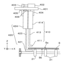
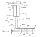
- FIGS. 3A and 3B are diagrams showing the general configuration of the chuck mechanism. Also, FIGS. 4A and 4B are diagrams showing the main parts of the chuck mechanism as viewed from the side. More specifically, FIG. 3A is a perspective view showing the structure of chuck mechanism 400, and FIG. 3B is a diagram showing the state in which chuck mechanism 400 grips substrate S. Also, FIG. 4A is a side view showing chuck mechanism 400 before gripping substrate S, and FIG. 4B is a side view showing chuck mechanism 400 when gripping substrate S.
- the explanation will be given mainly by way of example of the chuck mechanism 400 that holds the (-X) side end of the substrate S.
- the operation of the chuck mechanism 400 is controlled by the chuck control unit 912 of the control unit 9.
- the chuck mechanism 400 grips the X-direction end of the substrate S with an upper chuck 411 and a lower chuck 421, which can be raised and lowered independently of each other.
- the upper chuck 411 and the lower chuck 421 are each elongated flat members extending in the Y direction.
- the lower surface 411b of the upper chuck 411 abuts against the (-X) side end of the upper surface Sa of the substrate S
- the upper surface 421a of the lower chuck 421 abuts against the (-X) side end of the lower surface Sb of the substrate S, thereby gripping the substrate S.
- a cathode electrode 412 is attached to the lower surface 411b of the upper chuck 411, and the cathode electrode 412 comes into contact with the upper surface Sa of the substrate S.
- a seal member 415 made of an elastic material and having a ring shape is provided on the lower surface 411b of the upper chuck 411 so as to surround the periphery of the cathode electrode 412.
- the lower chuck 421 not only determines the position of the substrate S in the height direction (Z direction), but also acts as a backup when the cathode electrode 412 provided on the upper chuck 411 contacts the substrate S. This ensures that the height position of the substrate S is stably maintained and that electrical contact between the cathode electrode 412 and the substrate upper surface Sa is ensured.
- a shaft member 413 extending in the Z direction is attached to the upper surface 411a of the upper chuck 411, and the shaft member 413 is supported by a lifting mechanism 414 so that it can be raised and lowered.
- the upper chuck 411 is fixed to the shaft member 413 using a screw, for example, and is detachable (i.e. replaceable).
- the lifting mechanism 414 has an appropriate linear motion mechanism such as an air cylinder, a solenoid, a linear motor, or a ball screw mechanism, and raises and lowers the shaft member 413. This raises and lowers the upper chuck 411 attached to the lower end of the shaft member 413.
- the unit integrally formed including the upper chuck 411, the shaft member 413, the lifting mechanism 414, etc. is referred to as the "upper chuck unit 410.”
- a shaft member 423 extending in the Z direction is attached to the upper surface 421a of the lower chuck 421, and the shaft member 423 is supported by a lifting mechanism 424 so that it can be raised and lowered.
- the lower chuck 421 is fixed to the shaft member 423 using, for example, a screw, and is detachable.
- the lifting mechanism 424 has an appropriate linear motion mechanism, such as an air cylinder, a solenoid, a linear motor, or a ball screw mechanism, and raises and lowers the shaft member 423. This raises and lowers the lower chuck 421 attached to the lower end of the shaft member 423.
- the unit integrally formed including the lower chuck 421, the shaft member 423, the lifting mechanism 424, etc. is referred to as the "lower chuck unit 420.”
- the upper chuck unit 410 is attached to the support member 401. Specifically, the upper chuck unit 410 is fixed to the support member 401 via a fixing member 404. Therefore, the upper chuck 411 can only move up and down relative to the support member 401.
- the lower chuck unit 420 is attached to the support member 401 via a moving mechanism 402. Specifically, the support member 403 to which the lower chuck unit 420 is attached is connected to the movable part of the moving mechanism 402, which moves in the X direction.
- the moving mechanism 402 has an appropriate linear mechanism, such as an air cylinder, a solenoid, an air cylinder, a linear motor, or a ball screw mechanism, and its main body is fixed to the support member 401.
- a guide rail 405 is provided at the bottom of the support member 401, and a slider 406 engaged with the guide rail 405 is connected to the lower chuck unit 420.
- the lower chuck unit 420 can move in the X direction within a movable range defined by a stopper (not shown). Therefore, the lower chuck 421 can move up and down relative to the support member 401 by operating the lifting mechanism 424, and can move forward and backward in the X direction by the advance/retract mechanism 402.
- the (+X) side tip of the lower chuck 421 is located on the (+X) side of the end face of the substrate S, and the upper surface 421a of the lower chuck 421 can support the lower surface Sb of the substrate S.
- the (+X) side tip of the lower chuck 421 is retreated to the (-X) side of the end face of the substrate S. This prevents the lower chuck 421 from coming into contact with the substrate S when it is raised or lowered.
- the upper chuck 411 and the lower chuck 421 cooperate to grip the substrate S in the plating tank 41.
- the upper chuck 411 and the lower chuck 421 are lowered from the chuck mechanism 400 of the chuck section 40 positioned at the plating position into the plating tank 41 (FIG. 4A), and grip the edge of the substrate S at the same height as the substrate S supported and stationary by the transport rollers 21 in the plating tank 41 (FIG. 4B). Therefore, the substrate S is held in a horizontal position with a flat upper surface in the plating tank 41.
- the Z direction position of the upper chuck 411 and the lower chuck 421 at this time, as shown in FIG. 4B, will be referred to as the "lower position" below.
- the main parts of the chuck mechanism 400 are housed inside the cover 460.
- the cover 460 has a roughly rectangular box shape, and its internal space houses the movable mechanisms (chuck drive mechanisms) such as the lifting mechanisms 414, 424 and the advance/retract mechanism 402.
- An opening is provided on the underside of the cover 460, from which shaft members 413, 423 protrude downward, and upper and lower chucks 411, 421 are attached to the lower ends thereof, respectively.
- This cover 460 is provided to protect the movable mechanism from corrosive gases generated from the plating solution stored in the plating tank 41, and to prevent fine powder and the like generated from the movable mechanism from falling into the plating tank 41. Its detailed structure and function will be described later, and the plating process performed by the plating apparatus 1 of this embodiment configured as described above will be described first with reference to Figures 5 to 7. This plating process is realized by the CPU 91 of the control unit 9 executing a predetermined control program.
- FIG. 5 is a flow chart showing the plating process.
- FIGS. 6A to 6D and 7 are schematic diagrams showing the movement of each part during processing.
- An unprocessed substrate S is received when the plating apparatus 1 is in a predetermined initial state.
- the initial state is a state in which, as shown in FIG. 6A, each chuck mechanism 400 is positioned at the plating position, the shutters 41a and 41b of the plating tank 41 are open, and plating solution L is stored in the plating tank 41 to the extent that the transport path P is exposed.
- the transport unit 2 transports the substrate S in the transport direction Dt and loads it into the plating tank 41 (step S101).
- the shutters 41a and 41b are closed.
- the upper chuck 411 and the lower chuck 421 of the chuck mechanism 400 are lowered toward the substrate S contained in the plating tank 41, and grip the substrate S as shown in FIG. 6D (step S102).
- plating solution L is supplied from plating solution supply/discharge unit 49 to plating tank 41, and a voltage is applied between the electrodes while substrate S is immersed (step S103), thereby plating substrate S.
- Cathode electrodes extending long in the Y direction are brought into contact with both ends of upper surface Sa of substrate S in the X direction. This reduces the variation in electric field strength on upper surface Sa of substrate S, making it possible to form a plating film with good uniformity.
- the chuck mechanism 400 and transport rollers 21 work together to rock substrate S in plating tank 41 (step S104), thereby further improving the uniformity of the plating film.
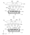
- the movement mechanism 43 operates to cause the support frame 430 supporting the chuck mechanism 400 to alternate between moving in the (+Dt) direction shown in the upper diagram of Figure 7 and moving in the (-Dt) direction shown in the lower diagram of Figure 7.
- the chuck mechanism 400 attached to the support frame 430 moves back and forth as a unit in the Y direction, and the substrate S held by the chuck mechanism 400 oscillates in the Y direction within the plating solution L.
- the transport rollers 21 work in conjunction with the support frame 430. That is, as shown in the upper diagram of FIG. 7, when the support frame 430 moves in the (+Y) direction and the chuck mechanism 400 moves the substrate S in the (+Y) direction, the transport rollers 21 rotate forward, that is, in a direction that transports the substrate S in the transport direction Dt. On the other hand, as shown in the lower diagram of FIG. 7, when the support frame 430 moves in the (-Y) direction and the chuck mechanism 400 moves the substrate S in the (-Y) direction, the transport rollers 21 rotate reversely, that is, to transport the substrate S in the (-Dt) direction opposite to the transport direction Dt.
- the rocking of the substrate S in the plating tank 41 is achieved by the cooperation of a chuck mechanism 400 that grips the edge of the substrate S and a transport roller 21 that supports the center of the substrate S from the underside. This prevents localized stress from being applied to the substrate S and makes it possible to rock the substrate S while maintaining a horizontal position.
- step S105 After the substrate S is immersed in the plating solution L and the substrate S is oscillated while a voltage is applied between the electrodes for a certain period of time, the voltage application is stopped and the plating solution L is discharged (step S105), thereby stopping the plating process. Then, the substrate S is released from the grip of the chuck mechanism 400 (step S106), and the transport unit 2 transfers the substrate S from the plating processing unit 4 to the rinsing processing unit 5 via the opened shutter 41b (step S107).
- the shutters 51a and 51b are closed, and rinse liquid is supplied from the rinse liquid supply/discharge section 59 to rinse the substrate S (step S108).
- the supply of rinse liquid is stopped, the shutter 51b is opened, and the substrate S is discharged to the discharge section 6 (step S109).
- the chuck mechanism 400 undergoes a cleaning process to remove the plating solution adhering to the upper chuck 411 and the lower chuck 421 (step S110).
- the contents of the cleaning process are arbitrary, but an example is as follows. That is, the moving mechanism 43 moves the support frame 430 in the (-Y) direction to position each chuck mechanism 400 at the cleaning position P2 (FIG. 1B) above the vat 44. In this state, the cleaning mechanism 48 cleans the chuck mechanism 400, more specifically the upper chuck 411 and the lower chuck 421, by supplying an appropriate cleaning liquid or spraying air.
- the upper chuck 411 and the lower chuck 421 are retracted upward by the lifting mechanisms 412, 422, as shown by the dotted lines in FIG. 1B. This prevents the upper chuck 411 and the lower chuck 421 from contacting the wall surface of the plating tank 41 during movement.
- the Z direction positions of the upper chuck 411 and the lower chuck 421 at this time will be referred to as the "upper position" below.
- the chuck mechanism 400 After cleaning, the chuck mechanism 400 is returned to the plating position (step S111). By cleaning the chuck mechanism 400 in this manner, it is possible to prevent any remaining plating solution from adhering to the substrate S when processing the next substrate S. If there are more substrates S to be processed, the process returns to step S101 and the above process is repeated.
- the cleaning process of the chuck mechanism 400 is shown as a step that follows the rinsing process.
- the chuck mechanism 400 can be moved to the cleaning position P2 at any time.
- the operation of transporting the substrate S to the rinsing processing section 5, rinsing the substrate S, and discharging the substrate S to the discharge section 6, and the operation of moving the chuck mechanism 400 to the cleaning position P2, cleaning the substrate S, and returning the substrate S to the plating position can be carried out in parallel.
- the chuck mechanism 400 of this embodiment is provided with a cover 460 that covers the movable mechanism to protect the movable mechanism from corrosive gases generated from the plating solution stored in the plating tank 41 and to prevent fine powder and the like generated from the movable mechanism from falling into the plating tank 41.
- Figure 8 is a three-view diagram showing the structure of the cover.
- the front and side views show the cover 460 in cross section.
- the cover 460 has a double box structure.
- the cover 460 has an approximately box-shaped inner cover 461 that houses the main parts of the chuck mechanism 400 in the internal space IS, and an outer cover 462 that is open at the top and covers the sides and bottom of the inner cover 461, and these are connected to each other via a spacer 463. Therefore, the sides and bottoms of the inner cover 461 and outer cover 462 face each other approximately parallel with a predetermined distance between them, and a gap space GS is formed between the inner cover 461 and outer cover 462.
- an opening 4611 is provided on the bottom surface of the inner cover 461, while an opening 4621 is also provided on the bottom surface of the outer cover 462 at a position corresponding to the opening 4611.
- shaft members 413, 423 protrude downward from inside the cover 460, and the upper chuck 411 and the lower chuck 421 are attached to their lower ends, respectively.
- the openings 4611, 4621 provided on the bottom surface are generally rectangular, but the four corners are partially blocked, making the opening shape octagonal. Note that the opening shape is not limited to this. It is desirable for the openings 4611, 4621 to be as small as possible as long as the operation of the chuck mechanism 400 is not hindered, and for this reason, the opening shape can also be appropriately modified according to the shapes of other parts.
- the support member 401 is connected to the inner cover 461, and although not shown, the upper part of the inner cover 461 is fixed to the support frame 430. In this way, the chuck mechanism 400 is supported by the support frame 430.
- the upper surface of the inner cover 461 is provided with an opening 4612 for connecting the internal space IS with an exhaust duct, which will be described later, and an exhaust pipe 4613 is connected to the opening 4612.
- a number of relatively small openings 4622 are provided on the side of the outer cover 462, and an appropriate valve mechanism 4623 is connected to each opening 4622.
- a valve capable of adjusting the flow rate such as a gate valve or throttle valve, can be suitably applied. Pressurized air is supplied to these valve mechanisms 4623 from an external air supply source, as will be described later.
- the mechanically movable parts of the chuck mechanism 400 are contained within the internal space IS of the cover 460 and are isolated from the surrounding atmosphere. Particularly at the plating position above the plating tank 41, corrosive gases, such as acid gases, generated from the plating solution L are present in relatively high concentrations. By covering the parts of the movable mechanism with the cover 460, the parts can be protected from such corrosive gases. Furthermore, even if dust is generated due to friction in the moving parts, the resulting fine powder is prevented from falling onto the plating tank 41 or the substrate S.
- the airflow inside the cover 460 is controlled. This prevents outside air from entering through the opening on the bottom, and also prevents fine powder generated inside the cover 460 from being discharged outside the device and falling toward the plating tank 41.
- FIG. 9 is a diagram explaining airflow control in the cover.
- the valve mechanism 4623 of the outer cover 462 is connected to an air supply source AS via appropriate piping. Pressurized air sent out from this air supply source AS is supplied to the gap space GS. Therefore, as shown by the solid arrows, the sent-in pressurized air passes through the gap space GS and is sprayed from the periphery of the opening on the bottom toward the center. The air curtain formed thereby acts to prevent the inflow of outside air, particularly the acidic atmosphere AA generated from the surface of the plating solution L.
- the exhaust pipe 4613 attached to the top of the inner cover 461 is connected to an exhaust duct 464 provided above the support frame 430.
- the exhaust duct 464 is connected to an appropriate exhaust device ES.
- the exhaust device ES When the exhaust device ES is activated, the atmosphere inside the cover 460 flows upward as shown by the dotted arrow, and is exhausted to the outside from the exhaust pipe 4613 through the exhaust duct 464.
- the rising air current thus formed pushes the fine powder generated in the internal space IS upward and exhausts it to the outside. This prevents the fine powder from falling into the plating tank 41.
- a throttle valve 4614 is arranged in the exhaust pipe 4613 to adjust the flow rate of the exhausted gas.
- the exhaust device ES and the air supply source AS may be provided as components within the plating device 1, or may be provided separately from the plating device 1 as external devices. For example, the power utilization of the factory facility in which the plating device 1 is installed may be utilized.
- the inventor's findings regarding the amount of air supplied from the air supply source AS and the amount of exhaust air exhausted by the exhaust device ES are as follows.
- the amount of exhaust air it is preferable that the flow rate (controlled air speed) of the airflow sucked in from the bottom opening of the cover 460 when there is no air blowing out of the gap space GS is, for example, 1.0 m/sec or more, based on the provisions of the Dust Prevention Regulations. This makes it possible to almost completely prevent fine powder from leaking out of the cover.
- the total amount of gas injected at the bottom of the cover 460 is greater than the amount of gas exhausted through the exhaust pipe 4613. In this way, almost all of the gas flowing upward from the bottom opening of the cover 460 and exhausted from the top is supplied from the air supply source AS. This makes it possible to effectively prevent the external acidic atmosphere AA from entering the cover 460.
- the gas that is sprayed at the bottom of the cover 460 and flows into the internal space IS functions as a purge gas that purges fine powder and the like remaining in the internal space IS.
- the gas that is not drawn into the cover 460 is sprayed downward from the bottom of the cover 460, which functions as an air curtain that prevents the acidic atmosphere AA from approaching the opening.
- the flow rate adjustment for these air supply and exhaust can be achieved by the flow rate control unit 914 of the control unit 9 controlling the valves 4614, 4623.
- the relationship between the opening 4611 on the bottom surface of the inner cover 461 and the opening 4621 on the bottom surface of the outer cover 462 is as follows. As shown in Figs. 8 and 9, it is preferable that the opening size of the opening 4621 on the outer cover 462 is slightly larger than the opening size of the opening 4611 on the inner cover 461. In other words, as shown in the front view and side view of Fig. 8, the peripheral portion of the opening 4611 extends further inward than the peripheral portion of the opening 4621, and when the inside of the cover 460 is viewed from the bottom side, it is preferable that the peripheral portion of the opening 4611 on the inner cover 461 is visible from the opening 4621 on the outer cover 462 without being obstructed.
- the direction of the sprayed gas has a large component that is slightly downward from the horizontal. This further increases the effect of blocking the acidic atmosphere AA rising from the surface of the plating solution L, making it possible to more reliably protect the components inside the cover 460.
- the opening area is as small as possible.
- the shape of the openings 4611, 4621 for this purpose can be, for example, rectangular, but according to the knowledge of the inventors of the present application, rectangular openings tend to allow outside air to enter through their four corners. As shown in the bottom view of Figure 8, in this embodiment, the openings 4611, 4621 are octagonal with the four corners of the rectangle sealed, thereby effectively preventing the inflow of outside air.
- a flexible protective tube called, for example, a cable carrier or cable chain (representatively referred to as a "cable carrier” below).
- a cable carrier or cable chain (representatively referred to as a "cable carrier” below).
- piping for air supply and exhaust in the cable carrier it is also conceivable to house piping for air supply and exhaust in the cable carrier.
- the piping particularly for exhaust, is large in diameter and requires mechanical strength, so it is not necessarily flexible. As a result, a large cable carrier is required to accommodate this piping, and the movement of the cable carrier is likely to be hindered. Also, although the piping for air supply can be thinner, the same problem still occurs when a large number of pipes are used, as in this embodiment.
- the plating apparatus 1 of this embodiment solves this problem as follows.
- a detachable joint mechanism is provided on the piping for air supply and exhaust, and while the piping is connected via the joint mechanism when the chuck mechanism 400 is in the plating position P1, the piping is allowed to be disconnected when the chuck mechanism 400 is in the cleaning position P2.
- the basic concept of the joint mechanism is the same for the air supply system that connects the air supply source AS and the cover 460, and the exhaust system that connects the exhaust device ES and the cover 460.
- the joint mechanisms in the exhaust system and the joint mechanisms in the air supply system are explained using separate diagrams.
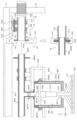
- FIG. 10 is a diagram explaining the joint mechanism in the exhaust system.
- the exhaust system piping is divided into chuck side piping provided in the chuck portion 40 and housing side piping provided in the housing 10, which are connected by a joint mechanism.
- the chuck side piping is mainly composed of an exhaust duct 464 attached to the support frame 430 and communicating with the internal space IS of the cover 460 of each chuck mechanism 400.
- the (+Y) side end 4641 of the exhaust duct 464 is open to the external space.
- a flange-shaped expanded diameter portion 4642 is formed on the outer surface near the end 4641.
- the exhaust duct 464 attached to the support frame 430 together with the chuck mechanism 400 also moves in the Y direction integrally with the chuck mechanism 400. Therefore, the exhaust duct 464 does not impede the movement of the chuck mechanism 400.
- the housing side piping includes a hollow pipe 12 and a support mechanism 13 for attaching it to the upper frame 11.
- a section of the pipe 12 on the (-Y) side is a first pipe 121 made of a resin material such as polyvinyl chloride resin or polyethylene resin or a metal material such as stainless steel, and this section does not require flexibility.
- the inner diameter of the first pipe 121 is formed to be approximately the same as the outer diameter of the exhaust duct 464, and it is arranged so that the central axes of the first pipe 121 and the exhaust duct 464 coincide with each other.
- a flange-shaped expanded diameter portion 1211 is formed at the (-Y) side end, and a seal member 123 made of, for example, rubber is attached to the (-Y) side end face of the expanded diameter portion 1211.
- the first pipe 121 is supported by a support mechanism 13.
- the support mechanism 13 includes a linear motion mechanism 130 attached to the upper frame 11.
- the linear motion mechanism 130 is arranged so that a guide rail 131 extends in the Y direction.
- a slider 132 and a clamper (linear clamp) 133 are attached to the guide rail 131, and a base member 134 is attached so as to straddle the slider 132 and the clamper 133.
- the base member 134 also moves in the Y direction.
- the clamper 133 also functions as a locking mechanism that restricts this movement.
- One or more (two in this example) coupling members 135 are attached to the base member 134, and the coupling members 135 mechanically couple the first pipe 121 to the base member 134. This supports the first pipe 121 so that it can move within a predetermined range in the Y direction.
- the second pipe 122 which is a flexible pipe such as a bellows tube, is connected to the (+Y) end of the first pipe 121 and constitutes the housing side pipe together with the first pipe 121.
- the movement of the first pipe 121 in the Y direction can be absorbed by the expansion and contraction of the second pipe 122. Therefore, the second pipe 122 and the exhaust device ES can be connected using an appropriate piping material.
- the exhaust duct 464 and the first piping 121 are mechanically coupled. This establishes a connection between the chuck side piping and the housing side piping, directly connecting their respective internal spaces, thereby forming an exhaust path from the cover 460 to the exhaust device ES.
- the locking mechanism 14 includes locking members 141, 142 that clamp the enlarged diameter portions 1211, 4642 from above and below, and a locking drive unit 143 (Fig. 2) that moves these members in the approaching and separating directions.
- a locking drive unit 143 Fig. 2
- the locking drive unit 143 moves the locking members 141, 142 in the approaching direction, thereby firmly connecting the exhaust duct 464 and the first pipe 121.
- the locking drive unit 143 moves the locking members 141, 142 in the separating direction, the connection between the exhaust duct 464 and the first pipe 121 can be released.
- the exhaust duct 464 and the first piping 121 are connected in this manner, and the atmosphere inside the cover 460 can be exhausted to the outside through the exhaust path thus formed.
- the dimensions and positional relationship of the exhaust duct 464 and the first piping 121 are set so that the connection between them is established when the chuck mechanism 400 is at the plating position P1.
- the support mechanism 13 and the lock mechanism 14 mainly function as a "joint mechanism” that detachably connects the chuck side piping (exhaust duct 464) and the housing side piping (first piping 121).
- the chuck mechanism 400 which holds the substrate S in the plating solution L, moves back and forth in the Y direction to rock the substrate S.
- the first pipe 121 can move back and forth in the Y direction following the exhaust duct 464 while remaining connected to it.
- the back and forth movement of the first pipe 121 can be absorbed by the second pipe 122.
- the joint mechanism of this embodiment can also accommodate the rocking of the substrate S caused by the chuck mechanism 400.
- FIG. 11 is a diagram explaining the joint mechanism in the air supply system. To avoid making the figure difficult to see, the illustration of the piping on the housing side and the joint mechanism in the exhaust system is omitted in FIG. 11. For the same reason, the illustration of the piping and joint mechanism in the air supply system is omitted in FIG. 10.
- a chuck side connector 465 is attached to the support frame 430.
- Flexible tubes 467 are connected from the (-Y) side end of the chuck side connector 465 via appropriate joints 466 to each valve mechanism 4623 of the cover 460.
- multiple chuck side connectors 465 may be provided on the support frame 430.
- a housing side connector 151 is provided on the housing 10 side.
- the housing side connector 151 is formed in a shape that engages with the chuck side connector 465, and is positioned so that it engages with the chuck side connector 465 when the chuck mechanism 400 moves to the plating position.
- a seal member 152 made of, for example, rubber is attached to the housing side connector 151.
- the housing-side connector 151 is supported by a support mechanism 16.
- the support mechanism 16 has a linear motion mechanism 160 attached to the housing 10 (upper frame 11) via an appropriate support member 18.
- the linear motion mechanism 160 is arranged so that a guide rail 161 extends in the Y direction.
- a slider 162 and a clamper (linear clamp) 163 are attached to the guide rail 161, and a base member 164 is attached so as to straddle the slider 162 and the clamper 163.
- a holding member 135 is attached to the base member 134, and the holding member 135 holds the housing side connector 151.
- a flexible tube 154 is connected to the (+Y) side end of the housing side connector 151 via an appropriate joint 153, and the flexible tube 154 connects the housing side connector 151 to the air supply source AS.
- the (+Y) end of the chuck side connector 465 eventually engages with the case side connector 151 via the seal member 152.
- the clamper 163 restricts the movement of the base member 164.
- the lock mechanism 17 operates in this state, the chuck side connector 465 and the case side connector 151 are mechanically coupled, thereby establishing a connection between the chuck side piping and the case side piping, and forming an air supply path from the air supply source AS to the cover 460.
- the locking mechanism 17 includes locking members 171, 172 that clamp the expanded diameter portions of the chuck side connector 465 and the case side connector 151 from above and below, and a locking drive unit 173 (Fig. 2) that moves these in the approaching and separating directions.
- a locking drive unit 173 (Fig. 2) that moves these in the approaching and separating directions.
- the drive unit 173 moves the locking members 171, 172 in the approaching direction, thereby firmly coupling the chuck side connector 465 and the case side connector 151.
- the drive unit 173 moves the locking members 171, 172 in the separating direction, the coupling between the chuck side connector 465 and the case side connector 151 can be released.
- the support mechanism 16 and the lock mechanism 17 mainly function as a "joint mechanism” that detachably couples the chuck side piping (chuck side connector 465) and the housing side piping (housing side connector 151).
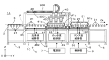
- FIG. 12 is a diagram showing the schematic configuration of a plating apparatus according to a second embodiment of the present invention.
- the plating apparatus 1A uses a cable carrier 900 to implement electrical wiring to the moving parts, which was omitted in the plating apparatus 1 of the first embodiment. Except for this point, the configuration and operation of each part are the same as in the first embodiment, so the same components are given the same reference numerals and descriptions are omitted.
- a cable carrier 900 is used to house the electrical wiring, but the air supply system and exhaust system are the same as those in the first embodiment. Therefore, there is no problem that the piping for air supply and exhaust puts a strain on the capacity of the cable carrier 900. Furthermore, as described above, there is no problem that the piping impedes the reciprocating movement of the chuck mechanism 400 between the plating position P1 and the cleaning position P2, or the oscillation during plating processing.
- some of the piping may be housed inside the cable carrier 900 as long as this does not restrict the capacity of the cable carrier 900.
- the plating apparatus 1, 1A each corresponds to one embodiment of the "substrate processing apparatus” of the present invention, and the substrate S to be processed corresponds to the “substrate” of the present invention.
- the chuck unit 40 and the moving mechanism 43 function as the “action unit” and the “moving mechanism” of the present invention, respectively, and the plating position P1 corresponds to the "first position” of the present invention, and the cleaning position P2 corresponds to the "second position" of the present invention.
- the exhaust duct 464 functions as the "movable pipe” of the present invention
- the pipe 12 functions as the “fixed pipe” of the present invention
- the lock mechanism 14 functions as the "connection mechanism” of the present invention.
- the flexible tube 467 functions as the "movable pipe” of the present invention
- the flexible tube 154 functions as the "fixed pipe” of the present invention
- the lock mechanism 17 functions as the "connection mechanism” of the present invention, and together these constitute the “flow path forming portion” of the present invention.
- the chuck side connector 465 and the housing side connector 151 correspond to the "engagement portion" of the present invention.
- the air supply source AS corresponds to the "fluid supply source” of the present invention
- the exhaust device ES corresponds to the "exhaust source” of the present invention.
- the upper chuck 411 and the lower chuck 421 function as a “holding portion” of the present invention
- the linear motion mechanisms 402, 414, and 424 function as both the “moving portion” and the “switching portion” of the present invention.
- both the intake system that supplies gas to the cover 460 and the exhaust system that exhausts gas from the cover 460 are configured to be separable via a "joint mechanism.”
- the piping of the intake system can be made relatively small and flexible, it is believed that the piping can be routed without interfering with the movement of the chuck mechanism 400.
- the cover member 460 has a double structure of an inner cover 461 and an outer cover 462, and the gap space GS between them serves as a flow path for the air for the air curtain.
- various structures other than the double structure of the cover itself can be considered as a configuration for spraying gas from the periphery toward the center of the opening at the bottom of the cover.
- a gas nozzle having a slit-shaped outlet that discharges gas in a substantially horizontal direction may be provided at the bottom of the cover.
- multiple outlets may be provided lined up in the horizontal direction.
- the chuck mechanism 400 grips the substrate S transported into the plating tank 41 by the transport rollers 21.
- the transport means is not limited to rollers and is optional.
- a configuration in which the substrate is transported while being gripped by the chuck mechanism is also conceivable.
- the transport means is not a required configuration, but in order to stably maintain the posture of a large substrate, it is desirable to provide some kind of backup means that supports the center of the substrate S from below.
- the chuck mechanism 400 of the above embodiment switches between a state in which the substrate S transported horizontally is gripped by the upper chuck 411 and the lower chuck 421, and a state in which the grip is released by moving these chucks away from each other.
- the application of the present invention is not limited to such a switching mode.
- the holding unit switches between a state in which the substrate is held in the plating solution and a state in which the substrate is held outside the plating solution.
- this applies to a configuration in which the holding unit raises and lowers the substrate while holding it, thereby immersing the substrate in the plating solution.
- the present invention can be suitably applied to such configurations as well.
- the substrate S is clamped and held by a pair of chuck members.
- the manner in which the substrate is held is not limited to this, and the present invention can be applied to plating devices with various holding modes, such as those that use the principle of vacuum suction, those that utilize magnetic force, and those that hold the peripheral edge of the substrate with a picture frame.
- the internal space of the cover 460 is connected to the exhaust duct through an opening provided at the top of the cover.
- an upward airflow is generated in the internal space, and fine powder generated by dust is exhausted to the outside by this airflow.
- the position of the opening for exhaust is not limited to this, and the exhaust may be configured to be exhausted from the side of the cover, for example.
- the rotation direction of the transport rollers 21 is switched in conjunction with the reciprocating movement of the chuck mechanism 400.
- the transport rollers 21 may be disconnected from the drive source and configured to rotate in response to the oscillation caused by the chuck mechanism 400.
- a configuration that can be separated by a joint mechanism is adopted for the piping that circulates the pressurized air supplied to the cover 460 and the piping that circulates the exhaust air from the cover 460.
- a configuration can be applied not only to the circulation of gas, but also to the purpose of circulating various fluids such as liquids or gases containing liquids.
- the above embodiment is an application of the present invention to a substrate processing apparatus as a plating apparatus.
- the application of the present invention is not limited to this, and it can be applied to various types of substrate processing.
- the present invention can be suitably applied to an apparatus that performs electrolytic etching on a substrate, an apparatus that develops an exposed photosensitive layer on the substrate surface, etc.
- the movable pipe and the fixed pipe each have an internal space through which a fluid flows, and when the action part is in the first position, the internal space of the movable pipe and the internal space of the fixed pipe may be directly connected.
- the internal space of the movable pipe and the internal space of the fixed pipe communicate with each other, thereby forming a flow path for the fluid.
- the connection mechanism simply needs to be able to maintain a state in which the internal space of the movable pipe and the internal space of the fixed pipe are connected in this manner.
- the movable pipe and the fixed pipe may each have an engagement portion that engages with each other when the action portion is in the first position, and the connection mechanism may be configured to fix the movable pipe and the fixed pipe that are engaged at the engagement portion.
- the movable pipe and the fixed pipe form a fluid flow path by engaging with each other at their engagement portions, and the connection mechanism can fix them to each other to maintain a stable flow path.
- the action part may have a movable part that switches between a state in which it acts on the substrate and a state in which the action is released, and a cover that covers the movable part, and the flow path forming part may be configured such that a fixed pipe is connected to an exhaust source and exhaust air from the cover flows as a fluid.
- dust generated in the movable part can be discharged to the outside together with the exhaust air, preventing its effect on the substrate.
- a large-diameter pipe is required for such an exhaust flow path, by applying the present invention, it is possible to use such a large-diameter pipe without affecting the movement of the action part.
- the flow path forming portion may be connected to a fluid supply source that supplies fluid to the action portion. That is, the fluid flowing through the formed flow path may flow from the fluid supply source toward the action portion.
- the action portion may have a movable portion that switches between a state in which it acts on the substrate and a state in which the action is released, and a cover that covers the movable portion, and may be configured to circulate purge gas that is supplied as a fluid into the cover.
- the action portion may have a movable portion that is driven by fluid supplied from the fluid supply source. In any of these configurations, it is possible to supply fluid and operate the movable portion when the action portion is in the first position.
- the flow path forming section may have a support mechanism that supports at least a portion of the fixed pipe so that it can swing within a predetermined swing range in a direction parallel to the moving direction of the action section.
- the substrate processing apparatus may further include a plating tank for storing a plating solution
- the operating section may include a holding section for contacting the substrate in the plating tank at the first position to hold the substrate, and a switching section for driving the holding section to switch between a state in which the substrate is held and a state in which the holding is released.
- the substrate processing apparatus configured in this manner can function as a plating processing apparatus that immerses the substrate in the plating solution to perform plating processing.
- This invention can be applied to substrate processing equipment and substrate processing methods in general that use fluids to perform predetermined operations on various substrates, such as printed wiring boards and glass substrates.
- it can be suitably applied to a technique in which a substrate is immersed in a plating solution to perform a plating process and form a coating.
Landscapes
- Chemical & Material Sciences (AREA)
- Engineering & Computer Science (AREA)
- Chemical Kinetics & Catalysis (AREA)
- Electrochemistry (AREA)
- Materials Engineering (AREA)
- Metallurgy (AREA)
- Organic Chemistry (AREA)
- Electroplating Methods And Accessories (AREA)
- Container, Conveyance, Adherence, Positioning, Of Wafer (AREA)
- Cleaning Or Drying Semiconductors (AREA)
- Coating Apparatus (AREA)
Abstract
Description
12 配管(固定配管、流路形成部)
13,16 支持機構
14,17 ロック機構(接続機構)
40 チャック部(作用部)
41 めっき槽
43 移動機構
151 筐体側コネクター(係合部位)
154 フレキシブルチューブ(固定配管、流路形成部)
402,414,424 直動機構(可動部、切替部)
411 上側チャック(保持部)
421 下側チャック(保持部)
460 カバー
464 排気ダクト(移動配管、流路形成部)
465 チャック側コネクター(係合部位)
467 フレキシブルチューブ(移動配管、流路形成部)
1211,4642 拡径部位(係合部位)
AS エア供給源(流体供給源)
ES 排気装置(排気源)
P1 めっき位置(第1位置)
P2 洗浄位置(第2位置)
S 基板
Claims (11)
- 第1位置に位置決めされて、流体を用いて基板に対する所定の動作を行う作用部と、
前記作用部を、互いに異なる前記第1位置と第2位置との間で移動させる移動機構と、
前記第1位置に位置決めされた前記作用部に接続されて、前記流体が流通する流路を形成する流路形成部と
を備え、
前記流路形成部は、
前記移動機構により前記作用部と一体的に移動する移動配管と、
前記流体の流通源に接続され、前記移動機構による前記作用部の移動に追随しない固定配管と、
前記作用部が前記第1位置に位置決めされているときに前記移動配管と前記固定配管とを接続し、前記作用部が前記第1位置から離間するときには該接続を解除する接続機構と
を有する、基板処理装置。 - 前記移動配管および前記固定配管は、前記流体が流通する内部空間をそれぞれ有し、
前記作用部が前記第1位置にあるとき、前記移動配管の前記内部空間と前記固定配管の前記内部空間とが直接接続される、請求項1に記載の基板処理装置。 - 前記移動配管および前記固定配管は、前記作用部が前記第1位置にあるときに互いに係合する係合部位をそれぞれ有し、
前記接続機構は、前記係合部位で係合された前記移動配管と前記固定配管との間を固定する、請求項2に記載の基板処理装置。 - 前記作用部は、前記基板に作用する状態と該作用を解除した状態とを切り替える可動部と、前記可動部を覆うカバーとを有し、
前記流路形成部は、前記固定配管が排気源に接続されて、前記流体として前記カバーからの排気を流通させる、請求項1に記載の基板処理装置。 - 前記流路形成部は、前記作用部に対して前記流体を供給する流体供給源に接続される、請求項1に記載の基板処理装置。
- 前記作用部は、前記基板に作用する状態と該作用を解除した状態とを切り替える可動部と、前記可動部を覆うカバーとを有し、前記流体として前記カバー内に供給されるパージ用ガスを流通させる、請求項5に記載の基板処理装置。
- 前記作用部は、前記流体供給源から供給される前記流体により駆動される可動部を有する、請求項5に記載の基板処理装置。
- 前記流路形成部は、前記固定配管の少なくとも一部を、前記作用部の移動方向と平行な方向に所定の揺動範囲内で揺動可能に支持する支持機構を有する、請求項1に記載の基板処理装置。
- めっき液を貯留するめっき槽をさらに備え、
前記作用部は、前記第1位置において、前記めっき槽内で前記基板に当接して前記基板を保持する保持部と、前記保持部を駆動して前記基板を保持する状態と該保持を解除した状態とを切り替える切替部とを有する、請求項1ないし8のいずれかに記載の基板処理装置。 - 基板に対し所定の動作を行う作用部を、移動機構が互いに異なる第1位置と第2位置との間で移動させる工程と、
前記第1位置に位置決めされた前記作用部が、流体を用いて前記所定の動作を実行する工程と
を備え、
前記作用部には、前記移動機構により前記作用部と一体的に移動する移動配管と、前記流体の流通源に接続され、前記移動機構による前記作用部の移動に追随しない固定配管とが設けられ、
前記作用部が前記第1位置に位置決めされているときには、接続機構が前記移動配管と前記固定配管とを接続し、前記作用部が前記第1位置から離間するときには、前記移動配管と前記固定配管との接続を前記接続機構が解除する、基板処理方法。 - めっき液を貯留するめっき槽を設け、
前記作用部は、前記第1位置において、前記めっき槽内で前記基板に当接して前記基板を保持する、請求項10に記載の基板処理方法。
Priority Applications (1)
| Application Number | Priority Date | Filing Date | Title |
|---|---|---|---|
| CN202380086473.5A CN120380204A (zh) | 2023-02-22 | 2023-11-27 | 基板处理装置及基板处理方法 |
Applications Claiming Priority (2)
| Application Number | Priority Date | Filing Date | Title |
|---|---|---|---|
| JP2023-025750 | 2023-02-22 | ||
| JP2023025750A JP2024119105A (ja) | 2023-02-22 | 2023-02-22 | 基板処理装置および基板処理方法 |
Publications (1)
| Publication Number | Publication Date |
|---|---|
| WO2024176552A1 true WO2024176552A1 (ja) | 2024-08-29 |
Family
ID=92500712
Family Applications (1)
| Application Number | Title | Priority Date | Filing Date |
|---|---|---|---|
| PCT/JP2023/042345 Ceased WO2024176552A1 (ja) | 2023-02-22 | 2023-11-27 | 基板処理装置および基板処理方法 |
Country Status (4)
| Country | Link |
|---|---|
| JP (1) | JP2024119105A (ja) |
| CN (1) | CN120380204A (ja) |
| TW (1) | TWI889090B (ja) |
| WO (1) | WO2024176552A1 (ja) |
Citations (1)
| Publication number | Priority date | Publication date | Assignee | Title |
|---|---|---|---|---|
| JP2002318378A (ja) * | 2001-04-22 | 2002-10-31 | Mikuni Denshi Kk | 液晶表示装置の組み立て方法とその装置 |
-
2023
- 2023-02-22 JP JP2023025750A patent/JP2024119105A/ja active Pending
- 2023-11-27 CN CN202380086473.5A patent/CN120380204A/zh active Pending
- 2023-11-27 WO PCT/JP2023/042345 patent/WO2024176552A1/ja not_active Ceased
- 2023-12-22 TW TW112150191A patent/TWI889090B/zh active
Patent Citations (1)
| Publication number | Priority date | Publication date | Assignee | Title |
|---|---|---|---|---|
| JP2002318378A (ja) * | 2001-04-22 | 2002-10-31 | Mikuni Denshi Kk | 液晶表示装置の組み立て方法とその装置 |
Also Published As
| Publication number | Publication date |
|---|---|
| TWI889090B (zh) | 2025-07-01 |
| TW202434761A (zh) | 2024-09-01 |
| CN120380204A (zh) | 2025-07-25 |
| JP2024119105A (ja) | 2024-09-03 |
Similar Documents
| Publication | Publication Date | Title |
|---|---|---|
| JP6503194B2 (ja) | 基板処理装置 | |
| US9027577B2 (en) | Nozzle and a substrate processing apparatus including the same | |
| KR100935990B1 (ko) | 기판처리장치 | |
| JP7137047B2 (ja) | Efem、及び、efemにおけるガス置換方法 | |
| CN103700606A (zh) | 基板处理装置 | |
| KR101453189B1 (ko) | 반송 장치 | |
| TWI765989B (zh) | 基板清洗裝置、基板清洗方法及基板清洗裝置之控制方法 | |
| JP4290075B2 (ja) | 基板保持用チャックの洗浄・乾燥装置及び基板保持用チャックの洗浄・乾燥方法 | |
| JP5004611B2 (ja) | 基板処理装置 | |
| KR20240049784A (ko) | 기판 처리 장치 및 방법 | |
| TWI808489B (zh) | 基板處理裝置及基板處理方法 | |
| JP2024119105A (ja) | 基板処理装置および基板処理方法 | |
| WO2024176553A1 (ja) | めっき装置 | |
| JP5263590B2 (ja) | 密閉容器の蓋開閉システム及び蓋開閉方法 | |
| KR20240118678A (ko) | 기판 처리 시스템 | |
| US20220390859A1 (en) | Substrate treating apparatus | |
| KR100521401B1 (ko) | 기판세정시스템 | |
| KR100564622B1 (ko) | 반도체 웨이퍼의 린스 및 건조장치 및 방법 | |
| KR100565433B1 (ko) | 기판이송장치 및 그 장치를 사용한 기판세정시스템 | |
| KR101502858B1 (ko) | 마스크 세정 장치 및 마스크 세정 방법 | |
| JP3886651B2 (ja) | 基板搬送装置および基板処理装置 | |
| JP2004265908A (ja) | 基板乾燥装置及び基板乾燥方法 | |
| KR20210032143A (ko) | 기판 처리 방법 및 기판 처리 장치 | |
| JP2000100898A (ja) | 基板搬送装置 |
Legal Events
| Date | Code | Title | Description |
|---|---|---|---|
| 121 | Ep: the epo has been informed by wipo that ep was designated in this application |
Ref document number: 23924196 Country of ref document: EP Kind code of ref document: A1 |
|
| WWE | Wipo information: entry into national phase |
Ref document number: 202380086473.5 Country of ref document: CN |
|
| WWP | Wipo information: published in national office |
Ref document number: 202380086473.5 Country of ref document: CN |
|
| NENP | Non-entry into the national phase |
Ref country code: DE |
|
| 122 | Ep: pct application non-entry in european phase |
Ref document number: 23924196 Country of ref document: EP Kind code of ref document: A1 |