WO2024176472A1 - 摺動部材、及び、転がり軸受 - Google Patents
摺動部材、及び、転がり軸受 Download PDFInfo
- Publication number
- WO2024176472A1 WO2024176472A1 PCT/JP2023/016593 JP2023016593W WO2024176472A1 WO 2024176472 A1 WO2024176472 A1 WO 2024176472A1 JP 2023016593 W JP2023016593 W JP 2023016593W WO 2024176472 A1 WO2024176472 A1 WO 2024176472A1
- Authority
- WO
- WIPO (PCT)
- Prior art keywords
- rubber
- sheet
- thickness
- metal ring
- sliding member
- Prior art date
- Legal status (The legal status is an assumption and is not a legal conclusion. Google has not performed a legal analysis and makes no representation as to the accuracy of the status listed.)
- Ceased
Links
Images




Classifications
-
- F—MECHANICAL ENGINEERING; LIGHTING; HEATING; WEAPONS; BLASTING
- F16—ENGINEERING ELEMENTS AND UNITS; GENERAL MEASURES FOR PRODUCING AND MAINTAINING EFFECTIVE FUNCTIONING OF MACHINES OR INSTALLATIONS; THERMAL INSULATION IN GENERAL
- F16C—SHAFTS; FLEXIBLE SHAFTS; ELEMENTS OR CRANKSHAFT MECHANISMS; ROTARY BODIES OTHER THAN GEARING ELEMENTS; BEARINGS
- F16C33/00—Parts of bearings; Special methods for making bearings or parts thereof
- F16C33/72—Sealings
- F16C33/76—Sealings of ball or roller bearings
- F16C33/78—Sealings of ball or roller bearings with a diaphragm, disc, or ring, with or without resilient members
- F16C33/7816—Details of the sealing or parts thereof, e.g. geometry, material
- F16C33/782—Details of the sealing or parts thereof, e.g. geometry, material of the sealing region
- F16C33/7823—Details of the sealing or parts thereof, e.g. geometry, material of the sealing region of sealing lips
-
- F—MECHANICAL ENGINEERING; LIGHTING; HEATING; WEAPONS; BLASTING
- F16—ENGINEERING ELEMENTS AND UNITS; GENERAL MEASURES FOR PRODUCING AND MAINTAINING EFFECTIVE FUNCTIONING OF MACHINES OR INSTALLATIONS; THERMAL INSULATION IN GENERAL
- F16C—SHAFTS; FLEXIBLE SHAFTS; ELEMENTS OR CRANKSHAFT MECHANISMS; ROTARY BODIES OTHER THAN GEARING ELEMENTS; BEARINGS
- F16C19/00—Bearings with rolling contact, for exclusively rotary movement
- F16C19/52—Bearings with rolling contact, for exclusively rotary movement with devices affected by abnormal or undesired conditions
-
- F—MECHANICAL ENGINEERING; LIGHTING; HEATING; WEAPONS; BLASTING
- F16—ENGINEERING ELEMENTS AND UNITS; GENERAL MEASURES FOR PRODUCING AND MAINTAINING EFFECTIVE FUNCTIONING OF MACHINES OR INSTALLATIONS; THERMAL INSULATION IN GENERAL
- F16C—SHAFTS; FLEXIBLE SHAFTS; ELEMENTS OR CRANKSHAFT MECHANISMS; ROTARY BODIES OTHER THAN GEARING ELEMENTS; BEARINGS
- F16C41/00—Other accessories, e.g. devices integrated in the bearing not relating to the bearing function as such
- F16C41/002—Conductive elements, e.g. to prevent static electricity
-
- F—MECHANICAL ENGINEERING; LIGHTING; HEATING; WEAPONS; BLASTING
- F16—ENGINEERING ELEMENTS AND UNITS; GENERAL MEASURES FOR PRODUCING AND MAINTAINING EFFECTIVE FUNCTIONING OF MACHINES OR INSTALLATIONS; THERMAL INSULATION IN GENERAL
- F16J—PISTONS; CYLINDERS; SEALINGS
- F16J15/00—Sealings
- F16J15/16—Sealings between relatively-moving surfaces
- F16J15/32—Sealings between relatively-moving surfaces with elastic sealings, e.g. O-rings
- F16J15/3284—Sealings between relatively-moving surfaces with elastic sealings, e.g. O-rings characterised by their structure; Selection of materials
-
- F—MECHANICAL ENGINEERING; LIGHTING; HEATING; WEAPONS; BLASTING
- F16—ENGINEERING ELEMENTS AND UNITS; GENERAL MEASURES FOR PRODUCING AND MAINTAINING EFFECTIVE FUNCTIONING OF MACHINES OR INSTALLATIONS; THERMAL INSULATION IN GENERAL
- F16C—SHAFTS; FLEXIBLE SHAFTS; ELEMENTS OR CRANKSHAFT MECHANISMS; ROTARY BODIES OTHER THAN GEARING ELEMENTS; BEARINGS
- F16C19/00—Bearings with rolling contact, for exclusively rotary movement
- F16C19/02—Bearings with rolling contact, for exclusively rotary movement with bearing balls essentially of the same size in one or more circular rows
- F16C19/04—Bearings with rolling contact, for exclusively rotary movement with bearing balls essentially of the same size in one or more circular rows for radial load mainly
- F16C19/06—Bearings with rolling contact, for exclusively rotary movement with bearing balls essentially of the same size in one or more circular rows for radial load mainly with a single row or balls
-
- F—MECHANICAL ENGINEERING; LIGHTING; HEATING; WEAPONS; BLASTING
- F16—ENGINEERING ELEMENTS AND UNITS; GENERAL MEASURES FOR PRODUCING AND MAINTAINING EFFECTIVE FUNCTIONING OF MACHINES OR INSTALLATIONS; THERMAL INSULATION IN GENERAL
- F16C—SHAFTS; FLEXIBLE SHAFTS; ELEMENTS OR CRANKSHAFT MECHANISMS; ROTARY BODIES OTHER THAN GEARING ELEMENTS; BEARINGS
- F16C2202/00—Solid materials defined by their properties
- F16C2202/30—Electric properties; Magnetic properties
- F16C2202/32—Conductivity
-
- F—MECHANICAL ENGINEERING; LIGHTING; HEATING; WEAPONS; BLASTING
- F16—ENGINEERING ELEMENTS AND UNITS; GENERAL MEASURES FOR PRODUCING AND MAINTAINING EFFECTIVE FUNCTIONING OF MACHINES OR INSTALLATIONS; THERMAL INSULATION IN GENERAL
- F16C—SHAFTS; FLEXIBLE SHAFTS; ELEMENTS OR CRANKSHAFT MECHANISMS; ROTARY BODIES OTHER THAN GEARING ELEMENTS; BEARINGS
- F16C2208/00—Plastics; Synthetic resins, e.g. rubbers
- F16C2208/02—Plastics; Synthetic resins, e.g. rubbers comprising fillers, fibres
-
- F—MECHANICAL ENGINEERING; LIGHTING; HEATING; WEAPONS; BLASTING
- F16—ENGINEERING ELEMENTS AND UNITS; GENERAL MEASURES FOR PRODUCING AND MAINTAINING EFFECTIVE FUNCTIONING OF MACHINES OR INSTALLATIONS; THERMAL INSULATION IN GENERAL
- F16C—SHAFTS; FLEXIBLE SHAFTS; ELEMENTS OR CRANKSHAFT MECHANISMS; ROTARY BODIES OTHER THAN GEARING ELEMENTS; BEARINGS
- F16C2240/00—Specified values or numerical ranges of parameters; Relations between them
- F16C2240/40—Linear dimensions, e.g. length, radius, thickness, gap
- F16C2240/60—Thickness, e.g. thickness of coatings
-
- F—MECHANICAL ENGINEERING; LIGHTING; HEATING; WEAPONS; BLASTING
- F16—ENGINEERING ELEMENTS AND UNITS; GENERAL MEASURES FOR PRODUCING AND MAINTAINING EFFECTIVE FUNCTIONING OF MACHINES OR INSTALLATIONS; THERMAL INSULATION IN GENERAL
- F16C—SHAFTS; FLEXIBLE SHAFTS; ELEMENTS OR CRANKSHAFT MECHANISMS; ROTARY BODIES OTHER THAN GEARING ELEMENTS; BEARINGS
- F16C33/00—Parts of bearings; Special methods for making bearings or parts thereof
- F16C33/72—Sealings
- F16C33/76—Sealings of ball or roller bearings
Definitions
- This disclosure relates to sliding members and rolling bearings.
- Patent Document 1 A rolling bearing with an anti-electrolytic corrosion function is disclosed in Patent Document 1.
- the rolling bearing described in Patent Document 1 is a bearing that supports the rotating shaft of an electric motor mounted on an electric vehicle or the like.
- This rolling bearing comprises an outer ring, an inner ring, a number of balls arranged between the outer ring and the inner ring, and an annular seal (sliding member) that closes the end opening of the bearing internal space between the outer ring and the inner ring.
- the seal comprises an elastic material such as rubber that has electrical conductivity. The inner and outer peripheral edges of this elastic material are in contact with the inner and outer rings, respectively.
- the inner ring By the elastic material coming into contact with the inner and outer rings, the inner ring is electrically connected to the outer ring through the elastic material, and the flow of current between the inner ring and the balls and between the outer ring and the balls is suppressed, and electrolytic corrosion of the inner ring raceway, the outer ring raceway, and the balls is suppressed.
- the elastic material of the seal (sliding member) in Patent Document 1 has a certain degree of conductivity due to the carbon fiber being kneaded into the rubber.
- the present disclosure aims to increase the conductivity of the sliding member.
- a sliding member includes a sheet, a rubber, and a metal ring.
- the sheet is made of conductive fibers, is fixed in contact with a first member made of steel, and is in slidable contact with a second member made of steel;
- the rubber is A first rubber portion fixed to a surface of a first axial side of the metal ring; a second rubber portion fixed to a surface of a second axial side of the metal ring; a third rubber portion fixed to a surface of a second side in the axial direction of the metal ring and integral with the second rubber portion; and
- the sheet is A first sheet portion fixed to the second rubber portion; a second sheet portion fixed to the third rubber portion and connected to the first sheet portion,
- the first surface on the first axial side is a surface on the first axial side of the metal ring or a surface on the first axial side of the first rubber portion
- the second surface on the second axial side is a surface on the second axial side of the second rubber portion and/or the first sheet portion
- the rolling bearing of the present disclosure comprises an inner ring having an inner ring raceway; an outer ring having an outer ring raceway disposed radially outward of the inner ring raceway; a plurality of rolling elements rollably disposed between the inner ring raceway and the outer ring raceway; the sliding member according to (1) arranged radially between an axial end of the inner ring and an axial end of the outer ring, one of the inner ring and the outer ring is the first member, The other of the inner ring and the outer ring is the second member.
- the sliding member of the present disclosure includes a sheet that is a nonwoven or woven fabric formed from conductive fibers, and this sheet can reduce electrical resistance and increase conductivity more than an elastic material made of rubber mixed with carbon fibers. Therefore, the sliding member electrically connects the first member and the second member with the sheet, and an electric current can flow from one of the first member and the second member to the other via this sheet.
- FIG. 1 is a cross-sectional view showing an example of a rolling bearing according to the present disclosure.
- FIG. 2 is an enlarged cross-sectional view of the sliding member.
- FIG. 3 is an enlarged cross-sectional view of a radially outer portion of the sliding member of FIG.
- FIG. 4 is an enlarged cross-sectional view of a radially inner portion of the sliding member of FIG.
- FIG. 5A is a view of a circumferential part of the sliding member as viewed from the axial direction, from the bearing external space side.
- FIG. 5B is a cross-sectional view taken along line AA of FIG. 5A.
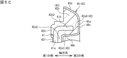
- FIG. 5C is a cross-sectional view taken along line BB in FIG. 5A.
- FIG. 6 is a cross-sectional view showing a molding die for the sliding member.
- FIG. 7 is an enlarged cross-sectional view showing a part of the molding die for the sliding member.
- FIG. 8 is an enlarged cross-sectional view of a portion of the molding die in an open state.
- a sliding member includes a sheet, a rubber, and a metal ring, the sheet is made of conductive fibers, is fixed in contact with a first member made of steel, and is in slidable contact with a second member made of steel;
- the rubber is A first rubber portion fixed to a surface of a first axial side of the metal ring; a second rubber portion fixed to a surface of a second axial side of the metal ring; a third rubber portion fixed to a surface of a second side in the axial direction of the metal ring and integral with the second rubber portion; and
- the sheet is A first sheet portion fixed to the second rubber portion; a second sheet portion fixed to the third rubber portion and connected to the first sheet portion,
- the first surface on the first axial side is a surface on the first axial side of the metal ring or a surface on the first axial side of the first rubber portion
- the second surface on the second axial side is a surface on the second axial side of the second rubber portion and/or the first sheet portion,
- the sliding member has a sheet that is a nonwoven or woven fabric made of conductive fibers, and the sheet can reduce electrical resistance and increase conductivity compared to an elastic material made of rubber mixed with carbon fibers. Therefore, the sliding member electrically connects the first member and the second member by the sheet, and an electric current can flow from one of the first member and the second member to the other via this sheet.
- the second thickness of the sliding member is greater than 0 mm and is greater than or equal to the first thickness
- the third thickness is greater than the first thickness and the second thickness.
- the metal ring of the sliding member of (1) above is disposed on a first axial side with a gap therebetween from the seat,
- the rubber has a portion disposed in the space.
- This configuration prevents direct contact between the metal ring and the sheet, preventing the sheet from being damaged by load from the metal ring.
- the rubber of the sliding member of (1) or (2) above is bonded to the entire first axial side of the sheet.
- This configuration allows the overall shape of the sheet to be maintained by the rubber, and prevents the sheet from breaking during manufacturing, preventing loss of conductivity.
- the rolling bearing of the present disclosure has an inner ring having an inner ring raceway; an outer ring having an outer ring raceway disposed radially outward of the inner ring raceway; a plurality of rolling elements rollably disposed between the inner ring raceway and the outer ring raceway; and a sliding member according to any one of (1) to (3) above, which is disposed radially between an axial end of the inner ring and an axial end of the outer ring, one of the inner ring and the outer ring is the first member, The other of the inner ring and the outer ring is the second member.
- the outer and inner rings of the rolling bearing can be electrically connected by a sheet of sliding material, and electric current can be passed from one of the outer and inner rings to the other via this sheet, suppressing electrical corrosion of the outer ring raceway, inner ring raceway, and balls.
- FIG. 1 is a cross-sectional view showing an example of a rolling bearing according to the present disclosure.
- a rolling bearing 10 shown in Fig. 1 supports a rotating shaft S of a motor mounted in, for example, an electric vehicle or a hybrid vehicle.
- the rotating shaft S is indicated by a virtual line (two-dot chain line).
- the rolling bearing 10 includes an outer ring 11, an inner ring 12, a plurality of rolling elements 13, a cage 14, and a sliding member 15.
- the rolling elements 13 are balls.
- the rolling bearing 10 is a deep groove ball bearing.
- the outer ring 11 is attached to a housing H of a motor.
- the inner ring 12 is fitted to and fixed on the outer circumferential surface of a rotating shaft S.
- the housing H is shown by a virtual line (two-dot chain line).
- the outer ring 11 is a fixed ring
- the inner ring 12 is a rotating ring.
- the outer ring 11 and the inner ring 12 are formed of a steel material such as bearing steel.
- the bearing steel a high carbon chromium bearing steel (for example, SUJ2 or SUJ3 as specified by the JIS standard) can be used.
- the outer ring 11 and the inner ring 12 may be made of other steel materials such as carburized bearing steel, carbon steel, chromium steel, and stainless steel.
- the outer ring 11 and the inner ring 12 are arranged concentrically.
- the central axis of the outer ring 11 and the central axis of the inner ring 12 coincide with the central axis C of the rolling bearing 10.
- the direction along the central axis C and the direction parallel to the central axis C are defined as the "axial direction”.
- the direction perpendicular to the central axis C is defined as the "radial direction”.
- the direction along the circle centered on the central axis C is defined as the "circumferential direction”.
- the left side of FIG. 1 is the axial first side
- the right side of FIG. 1 is the axial second side
- FIG. 1 is the radial first side
- the lower side of FIG. 1 is the radial second side
- the radial first side is the radial outer side
- the radial second side is the radial inner side. Therefore, in the following description, the radial first side may be referred to as the radial outer side, and the radial second side may be referred to as the radial inner side.
- the outer ring 11 has an outer ring raceway 21, two shoulders 22, and two annular grooves 23.
- the outer ring raceway 21 is provided on the inner peripheral surface of the outer ring 11.
- the balls 13 roll on this outer ring raceway 21.
- the two shoulders 22 are provided on both axial sides of the outer ring raceway 21.
- the two annular grooves 23 are provided between the shoulders 22 and the side surfaces of the outer ring 11, respectively.
- the annular grooves 23 have a circumferentially continuous annular groove shape.
- the sliding member 15 is attached to the annular grooves 23 arranged on both axial sides of the outer ring 11. However, the sliding member 15 may be attached only to the annular grooves 23 arranged on one of the first and second axial sides of the outer ring 11. In this case, the annular grooves 23 to which the sliding member 15 is not attached may be omitted.
- the inner ring 12 has an inner ring raceway 31, two shoulders 32, and two sliding member contact surfaces 33.
- the inner ring raceway 31 is provided on the outer peripheral surface of the inner ring 12.
- the balls 13 roll on this inner ring raceway 31.
- the two shoulders 32 are provided on both axial sides of the inner ring raceway 31.
- the two sliding member contact surfaces 33 are provided between the shoulders 32 and the side surfaces of the inner ring 12.
- the sliding member contact surface 33 is provided in an annular shape around the entire circumference of the inner ring 12.
- the sliding member contact surface 33 is groove-shaped in a cross section including the central axis C of the inner ring 12.
- the radial inner end of the sliding member 15 is in contact with the sliding member contact surface 33.
- the balls 13 are arranged between the outer ring 11 and the inner ring 12.
- the balls 13 roll and contact the outer ring raceway 21 and the inner ring raceway 31.
- the multiple balls 13 are held at intervals in the circumferential direction by the annular cage 14.
- the cage 14 has an annular body 16 and a number of horns (pillars) 17.
- the annular body 16 is provided on the second axial side of the balls 13.
- the multiple horns (pillars) 17 are provided extending from the annular body 16 to the first axial side.
- the pocket 18 is a space between two circumferentially adjacent horns 17 on the first axial side of the annular body 16.
- the balls 13 are housed in the pocket 18.
- the pocket 18 is open on the first axial side.
- the sliding member 15 is annular.
- the sliding member 15 is attached and fixed to the outer ring (first member) 11, and is in sliding contact with the inner ring (second member) 12.
- the sliding member 15 is fixed to the outer ring 11 by fitting its radial outer end (end on the first radial side) into the annular groove 23 of the outer ring 11.
- the radial inner end (end on the second radial side) of the sliding member 15 contacts the sliding member contact surface 33 of the inner ring 12.
- the sliding member 15 is disposed on both axial sides of the rolling bearing 10. Therefore, the bearing internal space K1, which is an annular space between the outer ring 11 and the inner ring 12 and in which the balls 13 are present, is closed by the sliding member 15 on both axial sides.
- the sliding member 15 divides the bearing internal space K1 in which the balls 13 are present from the bearing external space K2, which is a space on the first and second axial sides of the rolling bearing 10.
- the sliding member 15 has a conductive sheet 43 arranged between the radial outer end and the radial inner end. At the radial outer end of the sliding member 15, the sheet 43 is exposed on the surface and is in contact with the annular groove 23 of the outer ring 11. At the radial inner end of the sliding member 15, the sheet 43 is exposed on the surface and is in contact with the sliding member contact surface 33 of the inner ring 12. Therefore, the sliding member 15 forms an electrical path for preventing current generated by a motor or the like from flowing between the outer ring 11 and the inner ring 12 via the rolling body 13.
- An oil film made of lubricating oil or grease is formed between the balls 13 and the inner ring raceway 31, and between the balls 13 and the outer ring raceway 21.
- the oil film has insulating properties. Due to the insulating properties of the oil film, the balls 13 and the inner ring raceway 31, and the balls 13 and the outer ring raceway 21 are insulated from each other. When an oil film is formed between the balls 13 and the inner ring raceway 31 and a potential difference of a predetermined value or less occurs between the balls 13 and the inner ring raceway 31, no current flows between the inner ring raceway 31 and the balls 13.
- the rolling bearing 10 of this embodiment is provided with a sliding member 15 that forms a current path, so that the potential difference between the outer ring 11 and the inner ring 12 is reduced by passing a current between the outer ring 11 and the inner ring 12 via the sliding member 15 before the potential difference between the balls 13 and the inner ring raceway 31 and the potential difference between the balls 13 and the outer ring raceway 21 become large.
- the potential difference between the outer ring 11 and the inner ring 12 By reducing the potential difference between the outer ring 11 and the inner ring 12, the occurrence of electrolytic corrosion of the balls 13, the inner ring raceway 31, and the outer ring raceway 21 is suppressed.
- Fig. 2 is an enlarged cross-sectional view of a sliding member
- Fig. 3 is an enlarged cross-sectional view of a radially outer portion of the sliding member of Fig. 2
- Fig. 4 is an enlarged cross-sectional view of a radially inner portion of the sliding member of Fig. 2.
- the first axial side can be rephrased as the bearing external space K2 side
- the second axial side can be rephrased as the bearing internal space K1 side.
- the sliding member 15 arranged on the second axial side (right side in FIG. 1) of the rolling bearing 10 is the same part as the sliding member 15 arranged on the first side, but is arranged inverted in the axial direction.
- the sliding member 15 has a metal ring 41, rubber 42, and a sheet 43.
- the metal ring 41, rubber 42, and sheet 43 are all annular.
- the metal ring 41 and rubber 42, and the rubber 42 and sheet 43 are bonded to each other, and are integrated as a whole.
- the metal ring 41 is formed from a metal such as zinc-plated steel or stainless steel.
- the metal ring 41 is formed by processing a plate material.
- the metal ring 41 includes an annular portion 41a and a cylindrical portion 41b.
- the annular portion 41a is arranged perpendicular to the axial direction.
- the cylindrical portion 41b is arranged parallel to the axial direction.
- the cylindrical portion 41b is arranged at the radial outer end of the annular portion 41a.
- the cylindrical portion 41b extends from the radial outer end of the annular portion 41a to the second axial side (the bearing internal space K1 side).
- the annular portion 41a and the cylindrical portion 41b of the metal ring 41 are formed by plastic processing the plate material into a substantially L-shaped cross section.
- the rubber 42 is conductive. Specifically, the rubber 42 is manufactured by blending a conductive material with, for example, synthetic rubber.
- the conductive material is carbon black, metal powder, etc. The specific structure of the rubber 42 will be described later, along with the structure of the sheet 43.
- the sheet 43 is made of a nonwoven or woven fabric made of conductive fibers.
- carbon fibers are used as the conductive fibers used in the sheet 43.
- other materials such as fibers made of conductive metals such as copper and nickel, may also be used as the conductive fibers.
- the electrical resistance of the sheet 43 is lower than the electrical resistance of the rubber 42. Therefore, the sheet 43 has a higher electrical conductivity than the rubber 42.
- the sheet 43 further contains a synthetic resin as a binder.
- the binder is fixed to the surface of a portion of the conductive fibers contained in the sheet 43.
- the sheet 43 in this embodiment is a nonwoven fabric or a woven fabric made of conductive fibers to which the binder is fixed.
- the sheet 43 integrally has an intermediate portion 44, a fixed portion 45, and a sliding portion 46.
- the fixed portion 45 is a portion that is located radially outward (first radial side) from the metal ring 41.
- the sliding portion 46 is a portion that is located radially inward (second radial side) from the metal ring 41.
- the intermediate portion 44 is a portion that is located between the fixed portion 45 and the sliding portion 46.
- the intermediate portion 44 of the seat 43 has a first portion (first seat portion) 44a1, a second portion (second seat portion) 44a2, a third portion 44b, and a fourth portion 44c.
- the first portion 44a1 and the second portion 44a2 extend in the radial direction. As shown in Figures 3 and 4, the first portion 44a1 and the second portion 44a2 are arranged at intervals t11 and t12 on the second axial side (the bearing internal space K1 side) of the annular portion 41a of the metal ring 41.
- the second portion 44a2 is disposed on both radial sides of the first portion 44a1.
- the first portion 44a1 is located midway in the radial direction of the second portion 44a2.
- the first portion 44a1 and the second portion 44a2 are connected in the radial direction.
- the first portion 44a1 is located on the first axial side (the bearing external space K2 side) of the second portion 44a2. Therefore, the distance t11 between the first portion 44a1 and the metal ring 41 is smaller than the distance t12 between the second portion 44a2 and the metal ring 41.
- the third portion 44b of the sheet 43 is bent from the radially outer end of the second portion 44a2 toward the second axial side and extends in an approximately axial direction. Therefore, the third portion 44b is approximately cylindrical. As shown in Figure 3, the third portion 44b is disposed radially inside the cylindrical portion 41b of the metal ring 41 with a distance t2 therebetween.
- the fourth portion 44c bends radially outward from the end of the third portion 44b on the second axial side and extends radially. As shown in FIG. 3, the fourth portion 44c is disposed on the second axial side of the cylindrical portion 41b of the metal ring 41 with a distance t3 between them. Therefore, the middle portion 44 of the sheet 43 and the metal ring 41 are disposed with distances t11, t12, t2, and t3 between them in the entire radial direction.
- the fixed portion 45 of the seat 43 is continuous with the fourth portion 44c of the intermediate portion 44. As shown in FIG. 3, the fixed portion 45 has a fifth portion 45a and a sixth portion 45b.
- the fifth portion 45a extends radially from the radially outer end of the fourth portion 44c of the intermediate portion 44.
- the sixth portion 45b extends from the radially outer end of the fifth portion 45a while inclining toward the first axial side and radially outward.
- the tip of the sixth portion 45b constitutes the radially outer end of the seat 43.
- the tip of the sixth portion 45b is in direct contact with the annular groove 23 of the outer ring 11.
- the fifth portion 45a of the fixed portion 45 is also in direct contact with the annular groove 23.
- the sliding portion 46 of the sheet 43 is continuous with the second portion 44a2 which is the intermediate portion 44.
- the portion of the sheet 43 which is disposed radially inward from the radial inner end of the metal ring 41 is the sliding portion 46.
- the sliding portion 46 extends in a straight line radially inward from the second portion 44a2 of the intermediate portion 44. Therefore, the second portion 44a2 of the intermediate portion 44 and the sliding portion 46 as a whole are annular in shape perpendicular to the axial direction.
- the radial inner end 46a of the sliding portion 46 is in direct contact with the sliding member contact surface 33 of the inner ring 12.
- the radial inner end 46a of the sliding portion 46 is bent toward the first axial side by contacting the sliding member contact surface 33.
- the rubber 42 is bonded to the sheet 43 and the metal ring 41.
- the rubber 42 is provided on the entire first axial side (the bearing external space K2 side) of the sheet 43.
- the rubber 42 has a first portion 42a1, a second portion 42a2, a third portion 42a3, a fourth portion 42a4, a fifth portion 42b, a sixth portion 42c, a seventh portion 42d, an eighth portion 42e, a ninth portion 42f, a tenth portion 42b2, and an eleventh portion 42b3.
- the first to fourth portions 42a1, 42a2, 42a3, and 42a4 of the rubber 42 are disposed at intervals t11, t12, t2, and t3 between the metal ring 41 and the sheet 43.
- the first to fourth portions 42a1, 42a2, 42a3, and 42a4 of the rubber 42 maintain the intervals t11, t12, t2, and t3 between the metal ring 41 and the sheet 43 so that the metal ring 41 and the sheet 43 are not directly bonded to each other.
- the first portion 42a1 of the rubber 42 is the portion of the rubber 42 to which the first portion 44a1 of the sheet 43 is adhered.
- the second portion 42a2 is the portion of the rubber 42 to which the second portion 44a2 of the sheet 43 is adhered. Therefore, the second portions 42a2 are disposed on both radial sides of the first portion 42a1.
- the surface of the first axial side (the bearing external space K2 side) of the first portion 42a1 and the surface of the first axial side of the second portion 42a2 are arranged on the same plane, and both are bonded to the surface of the second axial side (the bearing internal space K1 side) of the annular portion 41a of the metal ring 41.
- the surface of the second axial side of the first portion 42a1 is arranged closer to the first axial side than the surface of the second axial side of the second portion 42a2.
- the first portion 42a1 of the rubber 42 and the first portion 44a1 of the sheet 43 are continuous in the circumferential direction around the entire circumference of the sliding member 15. However, they may be provided at multiple locations spaced apart in the circumferential direction.
- the third portion 42a3 of the rubber 42 is bonded to the inner circumferential surface of the cylindrical portion 41b of the metal ring 41.
- the fourth portion 42a4 of the rubber 42 is bonded to an end surface on the second axial side of the cylindrical portion 41b.
- the fifth portion 42b of the rubber 42 is continuous with the fourth portion 42a4 on the radial outside.
- the fifth portion 42b is disposed in an area surrounded by the fixed portion 45 of the sheet 43 and the cylindrical portion 41b of the metal ring 41.
- the fifth portion 42b of the rubber 42 elastically supports the sixth portion 45b of the sheet 43 from the radial inside.
- the cylindrical portion 41b of the metal ring 41 supports the fifth portion 42b of the rubber 42 from the radial inside.
- the fixed portion (radial outer end) 45 of the sheet 43 is pressed against the annular groove 23 of the outer ring 11 by the elasticity of the fifth portion 42b of the rubber 42 supported by the cylindrical portion 41b of the metal ring 41, and is reliably brought into contact with the annular groove 23.
- Fig. 5A is a view of a circumferential portion of the sliding member as viewed from the axial direction from the bearing external space side
- Fig. 5B is a cross-sectional view taken along line AA in Fig. 5A
- Fig. 5C is a cross-sectional view taken along line BB in Fig. 5A.
- the fifth portion 42b of the rubber 42 has a recess 42b1 on the surface of the first side in the axial direction.
- the recess 42b1 is provided at a plurality of locations spaced apart in the circumferential direction. As shown in FIG.
- a portion of the outer circumferential surface of the cylindrical portion 41b of the metal ring 41 is covered with a thin film-like eleventh portion 42b3.
- a portion of the outer circumferential surface of the cylindrical portion 41b of the metal ring 41 is covered with a tenth portion 42b2 that is thicker than the eleventh portion 42b3.
- the recess 42b1 is provided at a plurality of locations spaced apart in the circumferential direction, but may be provided continuously around the entire circumference of the sliding member 15. In this case, the eleventh portion 42b3 is provided around the entire circumference of the sliding member 15.
- the sixth portion 42c of the rubber 42 extends radially inward from the radial inner end of the second portion 42a2 of the rubber 42.
- the sixth portion 42c is provided with a substantially constant thickness along the side surface of the first axial direction side of the sliding portion 46 of the sheet 43.
- the sixth portion 42c is annular and perpendicular to the axial direction.
- the seventh portion 42d of the rubber 42 bulges out from the tenth portion 42b2 and the eleventh portion 42b3 of the rubber 42 toward the first axial side, covers the surface of the first radial side and the first axial side of the annular portion 41a of the metal ring 41, and is bonded to said surface.
- the seventh portion 42d is continuous in the circumferential direction around the entire circumference of the sliding member 15. However, the seventh portion 42d may be provided at multiple locations spaced apart in the circumferential direction.
- the eighth portion 42e of the rubber 42 is disposed on the side surface of the metal ring 41 on the first axial side, from the radial outer end of the sixth portion 42c, past the radial inner end of the metal ring 41.
- the eighth portion 42e therefore has a generally L-shaped cross section, covers the radial inner end face of the annular portion 41a and the side surface on the first axial side, and is bonded to these surfaces.
- the eighth portion 42e is continuous in the circumferential direction around the entire circumference of the sliding member 15. However, the eighth portion 42e may be provided in multiple locations spaced apart in the circumferential direction.
- the seventh portion 42d and eighth portion 42e of the rubber 42 serve to firmly bond the rubber 42 to the metal ring 41, preventing the rubber 42 from falling off the metal ring 41.
- the ninth portion (first rubber portion) 42f of the rubber 42 is a thin film-like portion that covers the surface of the first axial side of the annular portion 41a of the metal ring 41.
- the ninth portion 42f is disposed radially between the seventh portion 42d and the eighth portion 42e.
- the radial outer end of the ninth portion 42f is integral with the seventh portion 42d.
- the radial inner end of the ninth portion 42f is integral with the eighth portion 42e.
- the axial thickness ta of the ninth portion 42f is smaller than the axial thicknesses of the seventh portion 42d and the eighth portion 42e. Therefore, as shown in FIG. 2, the sliding member 15 has a shape in which a part of the side surface on the first axial side is recessed.
- the ninth portion 42f is not necessarily required and may be omitted. In this case, the side surface on the first axial side of the metal ring 41 is exposed to the outside (external bearing space K2) between the seventh portion 42d and the eighth portion 42e in the radial direction.
- the slide member 15 includes a "surface S1," a "surface S2,” and a "surface S3" defined as follows.
- Surface S1 The surface on the first axial side of the ninth portion (first rubber portion) 42f of the rubber 42, or the surface on the first axial side of the metal ring 41 (when the ninth portion 42f is not present).
- Surface S2 The surface on the second axial side of the first portion (second rubber portion) 42a1 of the rubber 42 and/or the first portion (first sheet portion) 44a1 of the sheet 43.
- Surface S3 A surface on a second axial side of the second portion (third rubber portion) 42a2 of the rubber 42 and/or the second portion (second sheet portion) 44a2 of the sheet 43.
- the surface S1 and the surface S2 of the sliding member 15 are disposed at positions overlapping each other in the radial and circumferential directions.
- the sheet 43 has gaps between the conductive fibers, and the rubber 42 penetrates into the gaps of the sheet 43. Therefore, the surface S2 may be formed solely of the surface on the second axial side of the first portion 44a1 of the sheet 43, or may be formed, in addition to this surface, of the surface on the second axial side of the first portion 42a1 of the rubber 42 that penetrates into the first portion 44a1. Alternatively, the surface S2 may be formed solely of the surface on the second axial side of the first portion 42a1 of the rubber 42 that penetrates into the gaps of the first portion 44a1 of the sheet 43 and passes beyond the first portion 44a1.
- surface S3 may be composed solely of the surface on the second axial side of second portion 44a2 of sheet 43, or may be composed in addition to this surface of the second axial side of second portion 42a2 of rubber 42 that has penetrated into second portion 44a2.
- surface S3 may be composed solely of the surface on the second axial side of second portion 42a2 of rubber 42 that has penetrated into the gap in second portion 44a2 of sheet 43 and exceeded second sheet portion 44a2.
- the sliding member 15 includes a "thickness ta”, a "thickness tb”, and a "thickness tc" defined as follows.
- Thickness ta thickness from the surface of the first side of the metal ring 41 in the axial direction to the surface S1.
- Thickness tb thickness from the surface of the second side of the metal ring 41 in the axial direction to the surface S2.
- Thickness tc the thickness from the surface of the second side of the metal ring 41 in the axial direction to the surface S3.
- the thickness ta is substantially the thickness of the ninth portion 42f. If the ninth portion 42f is not present, the thickness ta is substantially 0. The thickness ta is smaller than the thickness tb. Furthermore, the thickness ta and the thickness tb are smaller than the thickness tc.
- the sliding member 15 includes a "surface S4,” a "surface S5,” and a "surface S6" defined below.
- Surface S4 the surface on the first radial side of the eleventh portion 42b3 of the rubber 42, or the surface on the first radial side of the cylindrical portion 41b of the metal ring 41 (when the eleventh portion 42b3 is not present).
- Surface S5 surface on the second radial side of the third portion 42a3 of the rubber 42 and/or the third portion 44b of the sheet 43.
- Surface S6 The surface of the first radial side of the tenth portion 42b2 of the rubber 42.
- the sliding member 15 includes a "thickness td", a "thickness te”, and a "thickness tf” defined as follows.
- Thickness td the thickness from the outer peripheral surface of the cylindrical portion 41b of the metal ring 41 to the surface S4.
- Thickness te thickness from the inner circumferential surface of the cylindrical portion 41b of the metal ring 41 to the surface S5.
- Thickness tf thickness from the outer peripheral surface of the cylindrical portion 41b of the metal ring 41 to the surface S6.
- the thickness td is substantially the thickness of the eleventh portion 42b3.
- the thickness td is substantially 0.
- the thickness td is smaller than the thickness te.
- the thickness td is smaller than the thickness tf.
- the thicknesses te and tf may be the same or different. In this embodiment, the thickness te is greater than the thickness tf.
- the rubber 42 has a higher rigidity than the sheet 43, the shape of the sheet 43 is maintained by the rubber 42. In addition, the shape of the middle portion 44 of the sheet 43 is also maintained by the metal ring 41.
- the sheet 43 is made of a nonwoven or woven fabric made of conductive fibers.
- the sheet 43 contains voids inside in the material state before the sliding member 15 is manufactured.
- the rubber 42 also exists in the voids of the sheet 43.
- the sliding member 15 is manufactured by inserting the metal ring 41 and the sheet 43 into a mold, vulcanizing the rubber material that constitutes the rubber 42 and molding it into a predetermined shape, and bonding the rubber material to the metal ring 41 and the sheet 43.
- this manufacturing process is also referred to as "vulcanization adhesion".
- the rubber 42 enters the voids in the sheet 43.
- the rubber 42 is easily bonded to the binder.
- the fixed portion 45 of the sheet 43 is exposed on the surface of the sliding member 15 and contacts the annular groove 23 of the outer ring 11.
- the sliding portion 46 of the sheet 43 is exposed on the surface of the sliding member 15 and contacts the sliding member contact surface 33 of the inner ring 12. Since the multiple conductive fibers constituting the sheet 43 are in contact with each other, the sheet 43 is conductive due to the contact between the conductive fibers from the fixed portion 45 to the sliding portion 46. Since the sheet 43 is in contact with the outer ring 11 and the inner ring 12, the outer ring 11 and the inner ring 12 are electrically connected via the sheet 43. Furthermore, the conductive rubber 42 contacts the sheet 43 and also contacts the metal ring 41. The outer ring 11 and the inner ring 12 are electrically connected via the metal ring 41 and the rubber 42, which are conductive, in addition to the sheet 43.
- the sliding member 15 of this embodiment can release electric charge from one of the fixed portion 45 and the sliding portion 46 to the other.
- the sliding member 15 of this embodiment can also release electric charge from one of the member that fixes the fixed portion 45 and the member on which the sliding portion 46 slides to the other.
- the rolling bearing 10 of this embodiment can release electric charge from one of the outer ring 11 and the inner ring 12 to the other via the sliding member 15, making it possible to suppress electrolytic corrosion of the balls 13 and the outer ring raceway 21 and inner ring raceway 31 on which the balls 13 roll.
- the seat 43 is disposed on the sliding member 15 at the second axial side (the side closest to the bearing internal space K1).
- the sliding member contact surface 33 provided on the inner ring 12 faces the first axial side (the side closest to the bearing external space K2). This makes it easier for the sliding portion 46 of the seat 43 to come into contact with the sliding member contact surface 33.
- the seat 43 of the sliding member 15 may be located on the first axial side of the sliding member 15.
- FIG. 6 is a cross-sectional view showing a molding die for a sliding member
- Fig. 7 is a cross-sectional view showing an enlarged portion of the molding die for a sliding member
- Fig. 8 is a cross-sectional view showing an enlarged portion of the molding die in an open state.
- the sliding member 15 is manufactured by compression molding (pressure molding) using a molding die 50.
- the molding die 50 of the sliding member 15 has an upper die 51 and a lower die 52.
- the upper die 51 has a recess 51a, a protrusion 51b, an annular surface 51c, an annular surface 51d, and an annular surface 51e.
- the annular surfaces 51c, 51d, and 51e are surfaces facing the lower die 52.
- the recess 51a is recessed from the radially inner annular surface 51c and the radially outer annular surface 51d of the recess 51a.
- the protrusion 51b protrudes from the radially inner annular surface 51e and the radially outer annular surface 51c of the protrusion 51b.
- the lower mold 52 includes recesses 52a, 52b, 52c, and 52d, a mounting surface 52e, an annular surface 52g, and an annular surface 52h.
- the recesses 52a, 52b, 52c, and 52d and the mounting surface 52e are recessed from the annular surfaces 52g and 52h.
- the recesses 52a, 52b, 52c, and 52d and the mounting surface 52e are collectively referred to as a recess 52j.
- Each of the recesses 51a, 52a, 52b, 52c, the mounting surface 52e and the protrusion 51b are annular about the axis C2.
- the recesses 52d of the lower die 52 are located at multiple locations spaced apart in the circumferential direction about the axis C2.
- the protrusion 51b of the upper die 51 fits into the recess 52j of the lower die 52.
- the recesses 52b and 52c of the lower die 52 are formed to be dug further down from the bottom surface of the recess 52a.
- the recess 51a is located radially inside the annular surface 51d and radially outside the annular surface 51c.
- the protrusion 51b is located radially inside the annular surface 51c and radially outside the annular surface 51e.
- the recess 52d is located on the radial inside of the annular surface 52g and on both circumferential sides of a portion of the annular surface 52g, and is located on the radial outside of the recess 52b.
- the recess 52b is located on the radial inside of the portion of the annular surface 52g and the recess 52d, and is located on the radial outside of the mounting surface 52e.
- the mounting surface 52e is located on the radial inside of the recess 52b and on the radial outside of the recess 52c.
- the recess 52c is located on the radial inside of the mounting surface 52e and on the radial outside of the recess 52a.
- the recess 52a is located on the radial inside of the recess 52c and on the radial outside of the annular surface 52h.
- the mounting surface 52e protrudes from the recess 52b towards the upper die 51, and protrudes from the recess 52c towards the upper die 51.
- the surface of the first axial side of the annular portion 41a of the metal ring 41 is placed on this mounting surface 52e.
- a regulating surface 52f is located between the recesses 52d adjacent in the circumferential direction.
- the outer peripheral surface of the cylindrical portion 41b of the metal ring 41 comes into contact with this regulating surface 52f, and the metal ring 41 is positioned in the radial direction.
- An adhesive is applied to the surface of the metal ring 41.
- the metal ring 41 is immersed in the adhesive, thereby applying the adhesive to the surface of the metal ring 41.
- the metal ring 41 to which the adhesive has been applied is placed on the placement surface 52e.
- a metal ring 41, a sheet 43, and an unvulcanized rubber material G are placed between an upper mold 51 and a lower mold 52 which are separated and opened.
- the unvulcanized rubber material G is formed in a sheet shape.
- the sheet 43 and the rubber material G are placed between the upper mold 51 and the lower mold 52 in an overlapping state. Since the unvulcanized rubber material G has high adhesion, it is adhered to the sheet 43 by overlapping it on the sheet 43. This prevents misalignment between the sheet 43 and the rubber material.
- the recess 51a of the upper mold 51 and the annular surface 52g, recess 52d, and recess 52b of the lower mold 52 form the third portion 42a3, the fourth portion 42a4, the fifth portion 42b, the tenth portion 42b2, the eleventh portion 42b3, and the seventh portion 42d of the rubber 42 shown in FIG. 2.
- the third portion 44b, the fourth portion 44c, the fifth portion 45a, and the sixth portion 45b of the sheet 43 fit into this recess 51a and are formed into a shape that fits the inner surface of the recess 51a.
- the recess 52j of the lower mold 52 and the annular surface 51c, the protrusion 51b, and the annular surface 51e of the upper mold 51 form the first portion 42a1, the second portion 42a2, the sixth portion 42c, the eighth portion 42e, the ninth portion 42f, and the radially inner side of the seventh portion 42d of the rubber 42 shown in Figure 2.
- the first portion 44a1, the second portion 44a2, and the sliding portion 46 of the sheet 43 are sandwiched between the first portion 42a1, the second portion 42a2, and the sixth portion 42c of the rubber 42 and the annular surface 51c, the convex portion 51b, and the annular surface 51e of the upper die 51, and are molded into a shape that conforms to the annular surface 51c, the convex portion 51b, and the annular surface 51e. Therefore, the rubber 42 and the sheet 43 are formed into a shape that corresponds to the shapes of the annular surface 51c, the convex portion 51b, and the annular surface 51e of the upper die 51.
- the recess 52b of the lower mold 52 is a portion for molding the seventh portion 42d of the rubber 42 shown in Fig. 2.
- the recess 52c is a portion for molding the eighth portion 42e of the rubber 42.
- the recess 52d is a portion for molding the tenth portion 42b2 of the rubber 42.
- the sliding member 15 is manufactured by arranging the metal ring 41, the sheet 43, and the unvulcanized rubber material G between the upper mold 51 and the lower mold 52, closing the upper mold 51 and the lower mold 52, and applying pressure and heat.
- the pressurized unvulcanized rubber material G flows inside the mold 50 and fills the recesses 51a, 52a to 52d of the upper mold 51 and the lower mold 52.
- the unvulcanized rubber material G also enters the gaps in the sheet 43.
- the adhesive hardens and the unvulcanized rubber material G becomes rubber 42.
- the metal ring 41, the sheet 43, and the rubber 42 become one.
- the integrated part is cut away to form the sliding member 15.
- the rubber 42 and the sheet 43 are cut away along the cutting lines L1 and L2 shown in FIG. 6 to form the sliding member 15.
- unvulcanized rubber material G into sheet 43 and vulcanizing it, the rigidity of sheet 43 is increased and sheet 43 and rubber 42 become one body.
- the metal ring 41 is positioned in the vertical direction by being placed on the mounting surface 52e of the lower mold 52.
- the vertical gap between the metal ring 41 and the upper mold 51 is narrowed by the convex portion 51b of the upper mold 51, and the metal ring 41 is pressed from above by the convex portion 51b via the sheet 43 and rubber 42 (rubber material G). This prevents the metal ring 41 from floating up from the mounting surface 52e.
- the metal ring 41 is positioned in the radial direction by the regulating surface 52f of the lower mold 52.
- the rubber material G flows in the radial direction as shown by the white arrow in FIG. 6. Therefore, the metal ring 41 is likely to move in the radial direction within the mold 50.
- the rubber material G flows between the mounting surface 52e and the annular portion 41a of the metal ring 41, and the metal ring 41 is likely to float up.
- the mold 50 of this embodiment can position the metal ring 41 in an accurate position by the mounting surface 52e, the regulating surface 52f, and the convex portion 51b, and can also limit the movement of the metal ring 41. Therefore, the rubber 42 and the sheet 43 are fixed in an appropriate position relative to the metal ring 41.
- the sheet 43 is arranged in the mold 50 in a state where it is arranged along the upper mold 51, and the rubber material G arranged on the metal ring 41 side of the sheet 43 moves to the metal ring 41 side without breaking the sheet 43, so that the rubber material G does not break the sheet 43 and can prevent the conductivity from being impaired.
- a small amount of rubber material G gets in between the bottom surface of the metal ring 41 and the mounting surface 52e, forming a thin film-like portion (ninth portion) 42f (see FIG. 2).
- a small amount of rubber material G also gets in between the outer peripheral surface of the metal ring 41 and the regulating surface 52f, forming a thin film-like portion (eleventh portion) 42b3.
- these portions 42f, 42b3 do not necessarily have to be formed. If these portions 42f, 42b3 are not formed, the surface of the metal ring 41 will be exposed to the outside.
- the sliding member 15 includes a metal ring 41, rubber 42, and a sheet 43.
- the sheet 43 is made of conductive fibers, is fixed in contact with a first member (outer ring 11) made of steel, and is in slidable contact with a second member (inner ring 12) made of steel.
- the rubber 42 comprises a first rubber portion (ninth portion of rubber 42) 42f fixed to the surface of the first axial side of the metal ring 41, a second rubber portion (first portion of rubber 42) 42a1 fixed to the surface of the second axial side of the metal ring 41, and a third rubber portion (second portion of rubber 42) 42a2 fixed to the surface of the second axial side of the metal ring 41 and integral with the second rubber portion 42a1.
- the sliding member 15 comprises at least the second rubber portion 42a1 and the third rubber portion 42a2 of the first to third rubber portions 42f, 42a1, 42a2.
- the sheet 43 includes a first sheet portion 44a1 (a first portion of the middle portion 44 of the sheet 43) fixed to the second rubber portion 42a1, and a second sheet portion 44a2 (a second portion of the middle portion 44 of the sheet 43) fixed to the third rubber portion 42a2 and connected to the first sheet portion 44a1.
- the first surface S1 on the first axial side is the surface on the first axial side of the metal ring 41 or the surface on the first axial side of the first rubber portion 42f.
- the second surface S2 on the second axial side is the surface on the second axial side of the second rubber portion 42a1 and/or the first sheet portion 44a1.
- the third surface S3 on the second axial side is the surface on the second axial side of the third rubber portion 42a2 and/or the second sheet portion 44a2.
- the first surface S1 and the second surface S2 are arranged at positions that overlap each other in the radial and circumferential directions.
- the first thickness ta is the thickness from the surface of the first axial side of the metal ring 41 to the first surface S1.
- the second thickness tb is the thickness from the surface of the second axial side of the metal ring 41 to the second surface S2.
- the third thickness tc is the thickness from the surface of the second axial side of the metal ring 41 to the third surface S3.
- the second thickness tb exceeds 0 mm and is greater than the first thickness ta or is the same as the first thickness ta, and the third thickness tc is greater than the first thickness ta and the second thickness tb.
- the sheet 43 which is a nonwoven or woven fabric made of conductive fibers, can reduce electrical resistance and increase conductivity more than an elastic material made of rubber mixed with carbon fibers. Therefore, the sliding member 15 electrically connects the first member 11 and the second member 12 by the sheet 43, and can pass an electric current from one of the first member 11 and the second member 12 to the other via this sheet 43.
- the mold 50 for molding the sliding member 15 has a structure for pressing the metal ring 41 from both sides in the axial direction (vertical direction) as shown in Figs. 7 and 8.
- the mold 50 has a structure for pressing the metal ring 41 from both sides in the vertical direction by the mounting surface 52e and the protruding portion 51b. This makes it possible to suppress the positional deviation of the metal ring 41 with respect to the mold 50.
- the rubber 42 is adhered to the entire first axial side of the sheet 43, the overall shape of the sheet 43 can be maintained by the rubber, and the sheet will not break during manufacturing, preventing loss of electrical conductivity.
- the outer ring 11 is a fixed ring and the inner ring 12 is a rotating ring.
- the present invention may also be applicable to a case in which the outer ring 11 is a rotating ring and the inner ring 12 is a fixed ring.
- the sliding member 15 in the above embodiment is fixed to the outer ring 11, which is the first member, and is in sliding contact with the inner ring 12, which is the second member.
- the sliding member 15 may be fixed to the inner ring 12, which is the first member, and in sliding contact with the outer ring 11, which is the second member.
- the synthetic resin is fixed as a binder to the conductive fibers constituting the sheet 43.
- the conductive fibers constituting the sheet do not need to have a synthetic resin as a binder.
- the sliding member 15 in the above embodiment is used in the rolling bearing 10.
- the sliding member 15 of the present invention may be used in a device in which the sliding member 15 is fixed to one of two members that move relatively and is in slidable contact with the other member.
- the rolling bearing 10 is a deep groove ball bearing.
- the rolling bearing 10 may be an angular ball bearing, a roller bearing in which the rolling elements are rollers, or the like.
- the above-described embodiment is illustrative in all respects and is not restrictive.
- the scope of the present invention is defined by the claims, not the above-described embodiment, and includes all modifications within the scope equivalent to the configurations described in the claims.
Landscapes
- Engineering & Computer Science (AREA)
- General Engineering & Computer Science (AREA)
- Mechanical Engineering (AREA)
- Rolling Contact Bearings (AREA)
- Support Of The Bearing (AREA)
Applications Claiming Priority (2)
| Application Number | Priority Date | Filing Date | Title |
|---|---|---|---|
| JP2023027502 | 2023-02-24 | ||
| JP2023-027502 | 2023-02-24 |
Publications (1)
| Publication Number | Publication Date |
|---|---|
| WO2024176472A1 true WO2024176472A1 (ja) | 2024-08-29 |
Family
ID=92500520
Family Applications (4)
| Application Number | Title | Priority Date | Filing Date |
|---|---|---|---|
| PCT/JP2023/016593 Ceased WO2024176472A1 (ja) | 2023-02-24 | 2023-04-27 | 摺動部材、及び、転がり軸受 |
| PCT/JP2023/016605 Ceased WO2024176473A1 (ja) | 2023-02-24 | 2023-04-27 | 摺動部材、及び、転がり軸受 |
| PCT/JP2023/016610 Ceased WO2024176474A1 (ja) | 2023-02-24 | 2023-04-27 | 摺動部材、及び、転がり軸受 |
| PCT/JP2023/041120 Ceased WO2024176537A1 (ja) | 2023-02-24 | 2023-11-15 | 摺動部材、及び、転がり軸受 |
Family Applications After (3)
| Application Number | Title | Priority Date | Filing Date |
|---|---|---|---|
| PCT/JP2023/016605 Ceased WO2024176473A1 (ja) | 2023-02-24 | 2023-04-27 | 摺動部材、及び、転がり軸受 |
| PCT/JP2023/016610 Ceased WO2024176474A1 (ja) | 2023-02-24 | 2023-04-27 | 摺動部材、及び、転がり軸受 |
| PCT/JP2023/041120 Ceased WO2024176537A1 (ja) | 2023-02-24 | 2023-11-15 | 摺動部材、及び、転がり軸受 |
Country Status (4)
| Country | Link |
|---|---|
| JP (3) | JPWO2024176474A1 (https=) |
| CN (3) | CN120752446A (https=) |
| DE (3) | DE112023005863T5 (https=) |
| WO (4) | WO2024176472A1 (https=) |
Citations (2)
| Publication number | Priority date | Publication date | Assignee | Title |
|---|---|---|---|---|
| JP2009264401A (ja) * | 2008-04-22 | 2009-11-12 | Nsk Ltd | 通電式転がり軸受 |
| JP2015102200A (ja) * | 2013-11-27 | 2015-06-04 | 日本精工株式会社 | 車載モータ用転がり軸受 |
Family Cites Families (7)
| Publication number | Priority date | Publication date | Assignee | Title |
|---|---|---|---|---|
| JPS62106125A (ja) * | 1985-10-31 | 1987-05-16 | Uchiyama Mfg Corp | 密封材 |
| JP2009079643A (ja) * | 2007-09-26 | 2009-04-16 | Nsk Ltd | 通電式転がり軸受 |
| JP3191653U (ja) * | 2014-04-22 | 2014-07-03 | Nok株式会社 | オイルシール |
| DE102014010269B4 (de) * | 2014-07-11 | 2020-06-18 | Carl Freudenberg Kg | Vorschaltdichtung, Vorschaltdichtungsanordnung und Dichtring, umfassend die Vorschaltdichtung |
| JP6836152B2 (ja) * | 2017-01-26 | 2021-02-24 | Ntn株式会社 | 転がり軸受用シールの圧縮加硫成形用金型、及び転がり軸受用シールの製造方法 |
| DE102017107326A1 (de) * | 2017-04-05 | 2018-10-11 | Schaeffler Technologies AG & Co. KG | Elektrisch leitfähige Dichtung und Anordnung mit zwei gegeneinander abgedichteten Maschinenelementen |
| JP7475453B2 (ja) * | 2020-07-27 | 2024-04-26 | Nok株式会社 | 密封装置 |
-
2023
- 2023-04-27 WO PCT/JP2023/016593 patent/WO2024176472A1/ja not_active Ceased
- 2023-04-27 JP JP2025502089A patent/JPWO2024176474A1/ja active Pending
- 2023-04-27 WO PCT/JP2023/016605 patent/WO2024176473A1/ja not_active Ceased
- 2023-04-27 JP JP2025502088A patent/JPWO2024176473A1/ja active Pending
- 2023-04-27 DE DE112023005863.6T patent/DE112023005863T5/de active Pending
- 2023-04-27 DE DE112023005872.5T patent/DE112023005872T5/de active Pending
- 2023-04-27 CN CN202380094499.4A patent/CN120752446A/zh active Pending
- 2023-04-27 WO PCT/JP2023/016610 patent/WO2024176474A1/ja not_active Ceased
- 2023-04-27 CN CN202380094500.3A patent/CN120787288A/zh active Pending
- 2023-11-15 WO PCT/JP2023/041120 patent/WO2024176537A1/ja not_active Ceased
- 2023-11-15 JP JP2025502111A patent/JPWO2024176537A1/ja active Pending
- 2023-11-15 DE DE112023005873.3T patent/DE112023005873T5/de active Pending
- 2023-11-15 CN CN202380091796.3A patent/CN120569575A/zh active Pending
Patent Citations (2)
| Publication number | Priority date | Publication date | Assignee | Title |
|---|---|---|---|---|
| JP2009264401A (ja) * | 2008-04-22 | 2009-11-12 | Nsk Ltd | 通電式転がり軸受 |
| JP2015102200A (ja) * | 2013-11-27 | 2015-06-04 | 日本精工株式会社 | 車載モータ用転がり軸受 |
Also Published As
| Publication number | Publication date |
|---|---|
| WO2024176537A1 (ja) | 2024-08-29 |
| JPWO2024176537A1 (https=) | 2024-08-29 |
| JPWO2024176473A1 (https=) | 2024-08-29 |
| JPWO2024176474A1 (https=) | 2024-08-29 |
| CN120569575A (zh) | 2025-08-29 |
| WO2024176474A1 (ja) | 2024-08-29 |
| DE112023005872T5 (de) | 2025-12-04 |
| CN120787288A (zh) | 2025-10-14 |
| DE112023005863T5 (de) | 2025-12-04 |
| DE112023005873T5 (de) | 2025-12-11 |
| CN120752446A (zh) | 2025-10-03 |
| WO2024176473A1 (ja) | 2024-08-29 |
Similar Documents
| Publication | Publication Date | Title |
|---|---|---|
| US10006503B2 (en) | Release bearing and clutch release bearing device | |
| US20170268570A1 (en) | Ball Bearing | |
| US20110274384A1 (en) | Axial thrust bearing system | |
| JP7455540B2 (ja) | 転がり軸受 | |
| WO2024176472A1 (ja) | 摺動部材、及び、転がり軸受 | |
| WO2023233652A1 (ja) | 摺動部材、及び、転がり軸受 | |
| EP2740958B1 (en) | Ball bearing | |
| JP7737194B2 (ja) | 密封装置および電動機 | |
| JP2013002564A (ja) | 転がり軸受 | |
| KR20020002276A (ko) | 센터링 부시 | |
| WO2025224881A1 (ja) | 摺動部材、及び、転がり軸受 | |
| US20030210840A1 (en) | Stud-type roller bearing with tracking roller | |
| WO2024176308A1 (ja) | 摺動部材、及び、転がり軸受 | |
| EP2952765A1 (en) | Roller bearing | |
| WO2025262750A1 (ja) | 摺動部材、及び、転がり軸受 | |
| JP5889566B2 (ja) | 転がり軸受およびその製造方法 | |
| JP2012233548A (ja) | 転がり軸受 | |
| CN222910548U (zh) | 一种压缩机组件 | |
| WO2025069775A1 (ja) | 軸受シール | |
| WO2024262362A1 (ja) | 密封装置 | |
| JP2025129656A (ja) | 円環状導電部材 | |
| JP2024056385A (ja) | 絶縁転がり軸受 | |
| JP2025089009A (ja) | 密封装置、軸受装置及び密封装置の製造方法 | |
| WO2025084346A1 (ja) | 密封装置、軸受装置、及び密封装置の製造方法 | |
| JP2023130215A (ja) | 樹脂製の軌道輪を備えるクロスローラ軸受 |
Legal Events
| Date | Code | Title | Description |
|---|---|---|---|
| 121 | Ep: the epo has been informed by wipo that ep was designated in this application |
Ref document number: 23924119 Country of ref document: EP Kind code of ref document: A1 |
|
| NENP | Non-entry into the national phase |
Ref country code: DE |
|
| 122 | Ep: pct application non-entry in european phase |
Ref document number: 23924119 Country of ref document: EP Kind code of ref document: A1 |