WO2024176459A1 - 振動篩装置及び液吐出ユニット - Google Patents
振動篩装置及び液吐出ユニット Download PDFInfo
- Publication number
- WO2024176459A1 WO2024176459A1 PCT/JP2023/006837 JP2023006837W WO2024176459A1 WO 2024176459 A1 WO2024176459 A1 WO 2024176459A1 JP 2023006837 W JP2023006837 W JP 2023006837W WO 2024176459 A1 WO2024176459 A1 WO 2024176459A1
- Authority
- WO
- WIPO (PCT)
- Prior art keywords
- pipe
- screen
- liquid
- vibrating sieve
- sieve device
- Prior art date
- Legal status (The legal status is an assumption and is not a legal conclusion. Google has not performed a legal analysis and makes no representation as to the accuracy of the status listed.)
- Ceased
Links
Images








Classifications
-
- B—PERFORMING OPERATIONS; TRANSPORTING
- B03—SEPARATION OF SOLID MATERIALS USING LIQUIDS OR USING PNEUMATIC TABLES OR JIGS; MAGNETIC OR ELECTROSTATIC SEPARATION OF SOLID MATERIALS FROM SOLID MATERIALS OR FLUIDS; SEPARATION BY HIGH-VOLTAGE ELECTRIC FIELDS
- B03B—SEPARATING SOLID MATERIALS USING LIQUIDS OR USING PNEUMATIC TABLES OR JIGS
- B03B5/00—Washing granular, powdered or lumpy materials; Wet separating
- B03B5/02—Washing granular, powdered or lumpy materials; Wet separating using shaken, pulsated or stirred beds as the principal means of separation
- B03B5/04—Washing granular, powdered or lumpy materials; Wet separating using shaken, pulsated or stirred beds as the principal means of separation on shaking tables
Definitions
- the present invention relates to a vibrating sieve device and a liquid discharge unit used in the vibrating sieve device.
- Vibrating sieve devices are used at various industrial manufacturing sites, crushing sites, waste disposal sites, and other locations to separate powders, ores, waste, and other sorting objects according to size.
- a liquid such as water is discharged from a liquid discharge unit located above the vibrating screen onto the objects on the screen. This washes away any adhesions that may be attached to the objects and breaks up any clumps between the objects, allowing for highly accurate sorting.
- Patent Document 1 shows a wet vibrating sieve device equipped with a water spraying device equivalent to the liquid discharge unit described above.
- the water spraying device is equipped with a track provided above the sieve body, a traveling device that moves along the track, and a number of shower pipes that are provided on the traveling device and can shift the position at which water is discharged onto the screen. It shows that the shower pipes are configured by water tubes equipped with nozzles that are separably connected to each other via a four-way joint and a movable partition.
- the vibrating sieve device 101 is an inclined type vibrating sieve device that is vibrated by a vibration mechanism (not shown) and has a sieve body 102 that forms a sieve frame.
- the sieve body 102 is provided with a screen 103, for example, made of a sieve mesh.
- the sieve surface (upper surface) of the sieve mesh is inclined with respect to the horizontal plane, and the objects to be sorted that are supplied onto the sieve surface are sieved out while sliding down the sieve surface.
- the vibrating sieve device 101 is provided with a liquid discharge unit 104 that discharges water.
- the liquid discharge unit 104 has a water sprinkling section 105 and a hose 106 that supplies water to the water sprinkling section 105.
- the water sprinkler unit 105 is made up of multiple pipes connected to each other and has an outlet (not shown) that sprinkles water downward.
- the water sprinkler unit 105 is connected to a flexible hose 106 to ensure that movement, which will be described later, is not impeded.
- the screen 103 is detached from the sieve body 102 for replacement or maintenance. To remove the screen 103, an operator lifts the screen 103 above the sieve body 102 and moves it. To secure a working space and a moving space for the screen 103, it is necessary to move the water spraying part 105 on the screen 103.
- a large wet vibrating sieve device 101 may be used, and in that case, the water spraying part 105 becomes large and heavy.
- the figure shows an example in which a frame 107 made of steel frames is permanently installed. The water spraying part 105 is connected to a winch 108 installed on the frame 107, and the water spraying part 105 is lifted up.
- such a permanent frame 107 may not be installed, and a movable crane may be used. That is, a worker positions the crane near the vibrating sieve device 101 and uses the crane to hoist the water sprinkler unit 105, as shown by the dashed line in the figure.
- a framework 107 it will be costly to install and maintain it, and if a crane is used, it will be time-consuming to connect the water sprinkler unit 105 to the crane and to operate the crane.
- the vibrating sieve device 101 is provided inside a house, the height of the house will be relatively large because of the need to secure space above the water sprinkler unit 105 to install the framework 107 or use a crane.
- the sieve frame in order to move the unsieved sorting objects from the screen, is not configured to be installed around the entire circumference of the screen, but is configured to be open in the inclined direction. Therefore, when replacing or maintaining the screen, it is possible to move the screen to the side instead of moving it upwards, and to pass the objects through the open part of the sieve frame and pull them out to the outside of the sieve frame.
- another device or facility is installed at the destination to process the unsieved sorting objects, there may not be enough space to ensure such sideways movement.
- there are various types of screens used in vibrating sieve devices and in some cases the design does not allow for sideways movement.
- the present invention was made in consideration of these circumstances, and aims to provide a technology that can reduce the space required above a vibrating sieve device when attaching or detaching the screen of the vibrating sieve device, and can also reduce the labor and costs involved.
- the vibrating sieve device of the present invention (first invention) comprises: A screen is provided above an installation surface and supported relative to the installation surface; a vibration mechanism for vibrating the screen relative to the installation surface in order to sieve the material supplied onto the screen; a liquid discharge unit including: a first unit forming section that discharges liquid supplied from a liquid delivery mechanism onto the supply on the screen and has a discharge port whose position relative to the installation surface when the liquid is discharged is fixed; and a second unit forming section that is separable from the first unit forming section; Equipped with.
- the liquid discharge unit includes: a plurality of dispersion tubes each having a first portion extending in a horizontal direction and in which the discharge port is formed; a distribution pipe extending in the horizontal direction so as to intersect with the extending direction of the first portion, and having a connection portion to which one end of the dispersion tube is connected along the extending direction in order to distribute the liquid to each of the dispersion tubes; a supply pipe for supplying the liquid to the distribution pipe;
- the second unit forming portion is constituted by the supply pipe
- the first unit forming portion is a vibrating sieve device of the first invention, which is constituted by only the dispersion pipe out of the dispersion pipe and the distribution pipe, or by the dispersion pipe and the distribution pipe.
- the vibrating sieve device of the third invention is as follows:
- the second unit forming portion is constituted by the supply pipe and the distribution pipe,
- the vibrating sieve device of the second invention is characterized in that the first unit forming portion is constituted by the dispersion pipe and can be individually separated from the distribution pipe.
- the vibrating sieve device of the fourth invention is as follows: the second unit forming portion includes a pipe that forms a flow path upstream of a pipe that constitutes the first unit forming portion, an engaging portion and an engaging portion are provided on one of the pipes constituting the first unit forming portion and the pipes constituting the second unit forming portion, and an engaged portion is provided on the other pipe;
- This is a vibrating sieve device of any one of the first to third inventions, in which, when the one tube and the other tube are in contact, the engagement forming portion moves between a first position and a second position while maintaining a state of being connected to the one tube, thereby switching between forming an engagement between the engaging portion and the engaged portion and releasing the engagement to perform the separation.
- the vibrating sieve device of the fifth invention is as follows: a plurality of diffusion tubes each including a first portion extending laterally and in which the discharge port is formed, the diffusion tubes forming the first unit; a distribution pipe extending laterally in a direction intersecting with the extension direction of the first portion and including a connection portion to which one end of each of the dispersion pipes is connected along the extension direction in order to distribute the liquid to each of the dispersion pipes, forming the second unit; the diffuser tube has a second section bent relative to the first section and extending longitudinally; the connecting portion is a tube and has a third portion extending longitudinally therethrough and positioned above the second portion;
- the engaging portion, the engagement forming portion, and the engaged portion are provided on one of the second portion and the third portion, and the other of the second portion and the third portion, respectively.
- the vibrating sieve device of the sixth invention is a vibrating sieve device of any of the first to fifth inventions, in which the screen has a sieve surface that is inclined with respect to a horizontal plane, the inclination direction is open so that the supply material that slides down the sieve surface can move to the outside of the screen, and the screen is provided so as to be freely attached and detachable, and a sieve frame is provided that vibrates together with the screen by any of the vibration mechanisms.
- the vibrating sieve device of the seventh invention is the vibrating sieve device of the sixth invention, in which the first portion of the diffusion pipe is located in the inner area surrounded by the sieve frame.
- the vibrating sieve device of the eighth invention is the vibrating sieve device of the seventh invention, in which the lower end of the third portion is located in the inner area.
- the liquid discharge unit of the present invention comprises: A liquid discharge unit that supplies liquid to a vibrating sieve device including a screen that is provided above an installation surface and supported by the installation surface, and a vibration mechanism that vibrates the screen relative to the installation surface to sieve a material supplied onto the screen, a first unit forming section that discharges liquid supplied from a liquid sending mechanism onto the supply on the screen and has a discharge port that is fixed in position relative to the installation surface when the liquid is discharged; and a second unit forming section that is separable from the first unit forming section. Equipped with.
- the present invention reduces the space required above the vibrating sieve device when attaching or detaching the screen of the vibrating sieve device, and also reduces the labor and costs involved.
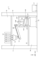
- FIG. 1 is a vertical cross-sectional side view of a house equipped with a vibrating sieve device according to an embodiment of the present invention.
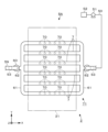
- FIG. 2 is a plan view of the vibrating sieve device.
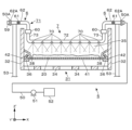
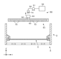
- FIG. 2 is a vertical sectional front view of the vibrating sieve device.
- FIG. 2 is a perspective view of the vibrating sieve device.
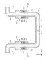
- 4 is a vertical cross-sectional side view of a distribution pipe and a sprinkling pipe that constitute a liquid discharge unit in the vibrating sieve device.
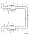
- FIG. FIG. 2 is a longitudinal sectional side view of the distribution pipe and the sprinkler pipe.
- 11A to 11C are explanatory diagrams showing a procedure for attaching and detaching the sprinkler pipe in the liquid discharge unit.
- FIG. 2 is a vertical cross-sectional side view of a house of a comparative example.
- FIG. 13 is a plan view showing a first modified example of the liquid discharge unit.
- FIG. 4 is a vertical sectional front view of a vibrating sieve device including the liquid discharge unit of the first modified example.
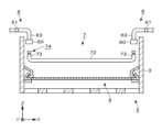
- FIG. 13 is a vertical sectional front view of a vibrating sieve device including a liquid discharge unit of a second modified example.
- FIG. 11 is a perspective view showing an engagement mechanism of the liquid discharge unit of the second modified example.
- FIG. 13 is a vertical sectional front view of a vibrating sieve device including a liquid discharge unit according to a third modified example.
- FIG. 1 is a vertical sectional front view of a conventional vibrating sieve device.
- FIG. 1 is a longitudinal side view.
- the house 1 is installed in a chemical plant, and powdered material 20 for manufacturing chemical products is supplied to the vibrating sieve device 2 as a material to be sorted (supply).
- the vibrating sieve device 2 is a wet, inclined type vibrating sieve device, and is installed on the floor surface 10 of a room 11 in the house 1. Therefore, the floor surface 10 forms the installation surface on which the vibrating sieve device 2 is installed.
- a hopper 13, a conveyor 14, and a chute 15 are installed in the room 11.
- a filter press 16 is installed in a room 12 on the floor above the floor including the room 11, and a tank 19 is installed in a room 18 on the floor below the floor including the room 11.
- the dehydrated cake produced from the slurry in the filter press 16 contains powder and granular materials 20, and this dehydrated cake is supplied to the conveyor 14 via the hopper 13. The cake is then supplied to the chute 15 and fed into the vibrating sieve device 2.
- the powder and granular materials 20 in the dehydrated cake that have been sieved by the vibrating sieve device 2 are stored as a slurry in a tank 19, for example, via a chute or pipe, but for convenience, FIG. 1 shows the sieved powder and granular materials 20 falling and being supplied directly to the tank 19. In addition to being stored in the tank 19 in this way, the slurry may also be supplied to equipment for the next process via a pump.
- the powder and granular materials 20 that have not been sieved are transferred to a transport vehicle 17 outside the house 1 via another transport mechanism (not shown), such as a conveyor, and sent to a designated processing facility.
- the vibrating sieve device 2 will be described with reference to the plan view, longitudinal front view, and perspective views of Figs. 2, 3, and 4.
- the X direction (left-right direction) and Y direction (front-back direction) are horizontal
- the Z direction is vertical
- Y' is the inclination direction
- Z' is a direction perpendicular to the X and Y' directions.
- the inclination direction is the direction along the screen 4, which will be described later, and the upper side in this inclination direction may be referred to as the upper inclination side, and the lower side may be referred to as the lower inclination side.
- the vibrating sieve device 2 includes a sieve body 3 and a liquid discharge unit 5, and a screen 4 is detachably attached to the sieve body 3.
- the sieve body 3 is composed of a side wall 32, a rear wall 33, a bottom lattice 34, a vibration mechanism 30, and a support portion 37. If the structure consisting of the side wall 32, the rear wall 33, and the bottom lattice 34 is the base 31, the base 31 is configured such that the upper wall and the front wall are removed from a square housing that is longer in the front-to-rear direction than in the left-to-right direction, and the bottom wall is replaced with the bottom lattice 34, and the sieved material passes through the bottom lattice 34 and falls below the base 31.
- Each side wall 32 has a protrusion 36 that protrudes into the inner region 35, and the protrusion 36 extends along the length of the side wall 32.
- the support parts 37 are connected to each side wall 32 at positions spaced apart from each other in the front and rear.
- the base 31 is supported by a total of four support parts 37, and the bottom grid 34 is tilted away from the floor surface 10 with the rear side positioned higher than the front side.
- the support parts 37 are composed of a base part 37A provided on the floor surface 10, a connection part 37B connected to the side wall 32 and provided above the base part 37A, and a coil spring 37C whose winding axis is aligned vertically.
- the spring 37C is interposed between the base part 37A and the connection part 37B to connect them to each other so that the sieve body 3 can be vibrated by the vibration mechanism 30 described below.
- the vibration mechanism 30 is composed of a drum 22, an unbalanced weight, and a motor 23, and the drum 22 is arranged to extend left and right between the protrusions 21.
- the sieve body 3 vibrates together with the screen 4 due to the centrifugal force generated when the unbalanced weight provided in the drum 22 is rotated by the motor 23 provided on one of the two protrusions 21.
- the screen 4 is composed of a sieve mesh 41 and two support members 42.
- the support members 42 are long in the front-rear direction and are provided separately on the left and right.
- the sieve mesh 41 is provided so as to span between the two support members 42.
- Each support member 42 is supported on the protrusion portion 36, and the sieve mesh 41 is provided along the X direction and the Y' direction, and is provided so as to face the upper surface of the bottom grid 34 and divide the inner region 35 into upper and lower parts.
- the support member 42 When viewed in the Y' direction, the support member 42 is formed into a horizontal V-shape by folding back the end opposite to the connection side to the sieve screen 41 upward, and the area surrounded by this V-shape forms a gap that opens toward the connection side to the sieve screen 41.
- a fixing member 38 is detachably attached to the side facing the inner area 35 of each side wall 32 of the sieve body 3 via a fixing device not shown. A part of the fixing member 38 attached to the side wall 32 in this way fits into the gap formed by the support member 42 placed on the protrusion portion 36, and the screen 4 is fixed to the sieve body 3.
- the lower end of the chute 15 opens to the rear side of the upper surface (sieve surface) of the sieve screen 41 fixed in this way, and the dehydrated cake containing the above-mentioned powder and granular material 20 is supplied to the sieve surface and slides down the sieve surface.
- the liquid discharge unit 5 is a unit that forms a water flow path downstream of the pump 51, which is a liquid delivery mechanism, and discharges water supplied from the water source 52 by the pump 51 so that it is sprayed onto the sieve screen 41. In order to prevent damage and deterioration, the liquid discharge unit 5 is not connected to the sieve body 3 so that it is not vibrated by the vibration mechanism 30.
- the liquid discharge unit 5 is composed of a supply pipe 50, two compound pipes 6, and six sprinkler pipes 7. Water supplied to the supply pipe 50 by the pump 51 flows through the compound pipe 6 and then the sprinkler pipe 7, and is discharged from the discharge port 70 provided on the sprinkler pipe 7.
- the compound pipe 6 and the sprinkler pipe 7 are collectively referred to as the sprinkler section 71.
- the sprinkler section 71 is arranged at an angle downward relative to the vibration mechanism 30.
- the sprinkler section 71 is configured symmetrically and is formed in a roughly ladder-like shape in a plan view, with the sprinkler pipes 7 forming the rungs of the ladder and the composite pipes 6 forming the frame and part of the rungs of the ladder.
- the six sprinkler pipes 7 are arranged in a line above the sieve screen 41 along the Y' direction, and have a first portion 72 that extends in the X direction and in which an outlet 70 is formed.
- the composite pipes 6 are arranged on the left and right sides of the sieve body 3, respectively, and are connected to each of the six sprinkler pipes 7.
- the supply pipe 50 described above is connected to only one of the two composite pipes 6.
- the water supplied from one composite pipe 6 to the sprinkler pipe 7 flows toward the other composite pipe 6, but is consumed by being released from the sprinkler pipe 7 before reaching the other composite pipe 6. Therefore, the other composite pipe 6 is not provided for the purpose of passing water, but is provided to support the sprinkler pipe 7 together with the first composite pipe 6.
- the composite pipe 6, which is the second unit forming part, has an attachment part 60 for forming an engagement with the sprinkler pipe 7, which is the first unit forming part.
- the sprinkler pipe 7 is fixed to the composite pipe 6, and when the engagement is released, the sprinkler pipe 7 can be separated from the composite pipe 6. Therefore, the sprinkler pipes 7 can be separated individually in the sprinkler part 71.
- the attachment and detachment of the sprinkler pipes 7 is performed to attach and detach the screen 4 to the sieve body 3, and the screen 4 can be attached and detached when the sprinkler pipe 7 is separated from the composite pipe 6. Note that Figures 2 to 4 show the state in which this engagement is formed and the sprinkler pipe 7 is fixed to the composite pipe 6.
- the composite pipe 6 will be further described.
- the composite pipe 6 is composed of a distribution pipe 61, a collecting pipe 62, and a connecting pipe 63.
- the distribution pipe 61 is arranged outside the base 31 of the sieve body 3 and above the base 31 in a plan view, and extends along the inclination direction.
- the center part of the distribution pipe 61 in the extension direction extends horizontally toward the opposite side to the side where the base 31 is located in the left-right direction, forming a collecting pipe 62, which is a short pipe.
- the collecting pipe 62 is supported by a support 53 extending from the floor surface 10. Six points separated from each other in the extension direction of the distribution pipe 61 extend horizontally toward the side where the base 31 is located in the left-right direction, forming a connecting pipe 63.
- the connecting pipe 63 extending horizontally in this manner bends on the left and right ends of the inner area 35 and extends vertically downward, with the lower end of the connecting pipe 63 entering the inner area 35 and positioned above the screen 4.
- the above-mentioned accessory part 60 is provided on the outer periphery of the lower end of this connecting pipe 63.
- the accessory part 60 will be described in detail later.
- Two connecting pipes 63 lined up on the left and right form one set. Therefore, six sets of connecting pipes 63 are provided.
- One sprinkler pipe 7 is connected to two connecting pipes 63 that form the same set. Therefore, the connecting pipe 63 forms a connection part provided on the distribution pipe 61 to connect the sprinkler pipe 7.
- the flange 50A formed at the downstream end of the supply pipe 50 and the flange 62A formed at the upstream end of the collecting pipe 62 are connected to each other. Water supplied from the supply pipe 50 to the collecting pipe 62 is distributed and supplied to each connecting pipe 63 via the distribution pipe 61, and then supplied to the sprinkler pipe 7. Therefore, the distribution pipe 61 is a so-called header pipe for distributing the water to each connecting pipe 63 in this way.
- the flange 62A of the collecting pipe 62 in the compound pipe 6 that is not connected to the supply pipe 50 is shown as being connected to the flange 50A formed at the downstream end of the pipe 59.
- the sprinkler pipe 7 is located in the inner region 35, and is configured with both ends of a straight pipe bent in the same direction. More specifically, the sprinkler pipe 7 has a first section 72 that extends horizontally in the left-right direction above the screen 4, and a second section 73 that is bent relative to the first section 72 and extends vertically, i.e., in the longitudinal direction. In this way, the extension direction of the first section 72 and the extension direction of the distribution pipe 61 are both horizontal, and these extension directions intersect (are not parallel to) each other.
- the outer diameter of the upper end of the second portion 73 is slightly smaller than the inner diameter of the lower end of the connecting pipe 63, and the upper end of the second portion 73 is inserted into the lower end of the connecting pipe 63. Therefore, the connecting pipe 63, which is the third portion, is located above the second portion 73.
- an annular groove 74 (not shown in Figures 1 to 4) is formed along the outer peripheral surface of the upper end of the second portion 73 that is inserted in this way. This annular groove 74 forms an engaged portion for forming an engagement with the compound pipe 6 by the above-mentioned attachment portion 60.
- discharge ports 70 are provided at intervals in the extension direction of the first portion 72, and open toward the sieve mesh 41 of the screen 4.
- the first portion 72 is arranged to overlap the screen 4 in a plan view.
- FIG. 5 and 6 which are longitudinal side views of the connecting pipe 63 and the sprinkler pipe 7 in the composite pipe 6, the engagement formed between the connecting pipe 63 and the sprinkler pipe 7 will be described.
- FIG. 5 shows the state in which the engagement is formed and the sprinkler pipe 7 is fixed to the connecting pipe 63, as in FIGS. 2 to 4.
- FIG. 6 shows the state in which the engagement is released and the sprinkler pipe 7 is removed from the connecting pipe 63.
- the end of the connecting pipe 63 is provided with a plurality of through holes spaced apart in the circumferential direction, and each through hole is provided with a ball 64.
- the parts above the through holes and the lower end protrude outward to form steps 65 and 66.
- a sleeve 67 is provided to surround the end of the connecting pipe 63, and an annular protrusion 68 is formed on the inner circumferential surface of the sleeve 67, protruding between the steps 65 and 66.
- a coil spring 69 is provided between the step 65 and the sleeve 67 to surround the connecting pipe 63.
- the above-mentioned attachment part 60 is composed of a sleeve 67, a ball 64, and a coil spring 69.
- the sleeve 67 which is the engagement forming part, is biased by the coil spring 69 to a lower position (second position) as shown in FIG. 5, but the operator can move the sleeve 67 to an upper position (first position) as shown in FIG. 6 against the biasing force of the coil spring 69.
- the sieve body 3 is vibrated by the vibration mechanism 30, and the powder 20 is supplied onto the screen 4.
- the pump 51 operates to discharge water (shown by dotted lines in Figures 3 and 4) from the discharge port 70 of the water sprinkler tube 7 onto the screen 4, and the water is supplied to the powder 20.
- the powder 20 is washed and sieved.
- a portion of the powder 20 is sieved and passes through the bottom grid 44 in the form of a slurry.
- a portion of the powder 20 moves to the outside of the sieve frame without being sieved.
- the water sprinkler tube 7 is fixed to the composite tube 6, and is supported against the floor surface 10 via the support 53 that supports the composite tube 6. Therefore, the position of the discharge port 70 when discharging water in this manner is fixed and does not move relative to the floor surface 10.
- Figures 7 to 9 are vertical cross-sectional views of the vibrating sieve device 2 viewed in the inclined direction.
- the worker moves each sleeve 67 of the two connecting pipes 63 of the same pair from the lower position to the upper position as explained in Figures 5 and 6, thereby releasing the engagement between the compound pipe 6 and the sprinkler pipe 7.
- the sprinkler pipe 7 is pulled out from the compound pipe 6 and removed ( Figure 7).
- the sprinkler pipes 7 are removed in order, for example, from one end to the other end in the inclined direction so that other sprinkler pipes 7 do not get in the way when removing them.
- the screen 4 can be removed from the sieve body 3 by removing the sprinkler pipe 7 from the liquid discharge unit 5, which is composed of a combination of piping. Because only a portion of the liquid discharge unit 5 is separated and removed in this manner, the weight of the components that need to be moved to remove the screen 4 is reduced, making the previously described frame 107 and crane unnecessary.
- FIG. 10 shows a longitudinal side view of the house 1 equipped with a vibrating sieve device 101 instead of the vibrating sieve device 2 and with a frame 107.
- a space is required above the vibrating sieve device 101 to install the frame 107 and a space is required to raise the sprinkler section 105 of the liquid discharge unit 104.
- a relatively large space is also required above the vibrating sieve device 101 when a crane is used without providing the frame 107.
- the materials to be processed are typically transported from top to bottom by gravity and processed sequentially by each piece of equipment. Therefore, providing a relatively large space above the vibrating sieve device 101 as described above means that the devices arranged upstream of the vibrating sieve device 101 in the movement path of the material to be treated are installed at a higher position by the space, compared to when the vibrating sieve device 2 is installed.
- Figures 1 and 10 show a filter press 16, a hopper 13, and a conveyor 14 as devices arranged upstream of the vibrating sieve devices 2 and 101. As shown in the figures, when the vibrating sieve device 101 is installed, these devices are installed at a higher position relative to the floor surface 10 than when the vibrating sieve device 2 is installed, and accordingly the height of the room 11 and therefore the height of the house 1 are greater.
- the vibrating sieve device 2 reduces the space required above, making it possible to reduce the height of the house 1. This prevents the construction of the house 1 from becoming inefficient and wasteful, and also prevents increases in construction costs and construction period. Furthermore, the vibrating sieve device 2 eliminates the construction costs of the frame 107, and eliminates the need to operate the crane and attach and detach the screen to the crane to be moved. Therefore, both the cost and labor required to replace the screen 4 can be reduced.
- the liquid discharge unit 5 is configured so that the sprinkler pipe 7 can be attached and detached by shifting the position of the sleeve 67 that forms the attachment part 60 on the composite pipe 6. This allows the engagement between the engaging part of the composite pipe 6 and the engaged part of the sprinkler pipe 7 to be switched between engagement and disengagement. This makes the attachment and detachment easy.
- the attachment part 60 remains connected to the composite pipe 6, and the engagement can be switched between engagement and disengagement by moving the position of the sleeve 67, eliminating the need to store parts that come off the piping, such as the bolts and nuts mentioned above. Therefore, the liquid discharge unit 5 reduces the amount of work required by the worker to replace the screen 4, and shortens the construction period.
- the sprinkler pipe 7 has a first portion 72 that extends horizontally and a second portion 73 that extends vertically downward by bending each of the first portion 72, and the worker attaches and detaches both ends of the sprinkler pipe 7 to and from the connecting pipe 63 by moving the sprinkler pipe 7 up and down. Therefore, when attaching or detaching one connection pipe 63 from the sprinkler pipe 7, the sprinkler pipe 7 does not interfere with the other connection pipes 63, so there is no need to remove the connection pipes 63 from the liquid discharge unit 5. In other words, the ends of each connection pipe 63 point downward, and both ends of the sprinkler pipe 7 are bent and point upward, which contributes to further reducing the labor required by the worker.
- the first portion 72 where the discharge port 70 is provided is located in the inner region 35 of the sieve body 3. Therefore, the distance between the discharge port 70 and the sieve surface is relatively short, and therefore high water pressure can be applied when spraying water onto the powdered or granular material 20 that is the sieved material, which is preferable because it makes the powdered or granular material 20 relatively easy to clean.
- the lower end of the connecting pipe 63 is located in the inner region 35, which means that the water sprinkler pipe 7 is located in the inner region 35. Therefore, the positioning of the lower end of the connecting pipe 63 contributes to relatively high cleanability.
- the configuration of the sprinkler section 71 is not limited to the above example.
- the sprinkler section 71 may be arranged so that the sprinkler tube 7 extends in the front-rear direction and the distribution tube 61 extends in the left-right direction, with the direction of the sprinkler section 71 changed by 90 degrees in plan view from the example already described.
- the position at which separation is performed is not limited to the example already described, and it is not limited to making the sprinkler tube 7 individually separable as in the examples described so far.
- Figures 11 and 12 show a vibrating sieve device 2 equipped with a liquid discharge unit 5A, which is a first modified example of the liquid discharge unit, instead of the liquid discharge unit 5.
- Figure 12 is a plan view of the vibrating sieve device 2
- Figure 12 is a vertical front view of the vibrating sieve device 2 as seen in an inclined direction.
- the liquid discharge unit 5A is attached and detached by forming and releasing the engagement between the sprinkler pipe 7 and the compound pipe 6
- the liquid discharge unit 5A is attached and detached by forming and releasing the engagement between the collecting pipe 62 of the compound pipe 6 and the supply pipe 50 and the piping 59. That is, in the liquid discharge unit 5A, the sprinkler section 71 is attached and detached as a whole, the first unit forming section is the sprinkler section 71, and the second unit forming section is the supply pipe 50 and the piping 59.
- the ends of the supply pipe 50 and the piping 59 connected to the compound pipe 6 are bent downward and are provided with an attachment section 60.
- the upstream end of the collecting pipe 62 in each compound pipe 6 is bent upward.
- the upstream end of one collecting pipe 62 is inserted into the supply pipe 50, and the upstream end of the other collecting pipe 62 is inserted into the piping 59.
- an annular groove 74 is formed in the upstream end of this collecting pipe 62 in order to form an engagement, similar to the sprinkler pipe 7 of the liquid discharge unit 5. Since an engagement is formed between the supply pipe 50 and the collecting pipe 62 as described above, the flanges 52A, 62A provided at the downstream end of the supply pipe 50 and the upstream end of the collecting pipe 62, respectively, in the liquid discharge unit 5 are not provided in the liquid discharge unit 5A.
- the liquid discharge unit 5A has a configuration in which the sprinkler pipes 7 are attached and detached as a whole, so the labor of the worker is more reliably reduced.
- the weight of the sprinkler section 71 increases and there is a risk that it may be difficult for the worker to support it, it is preferable to have a configuration in which the sprinkler pipes 7 can be attached and detached individually, as in the liquid discharge unit 5.
- the sprinkler pipe 7 is not attached and detached by forming and releasing the engagement between the composite pipe 6 and the sprinkler pipe 7, so the composite pipe 6 does not have a connecting pipe 63, and the sprinkler pipe 7 is not bent, so the second portion 73 is not provided.
- the sprinkler pipes 7, which are straight pipes, extend from positions separated from each other in the extension direction.
- the boundary between the composite pipe 6 and the sprinkler pipe 7 corresponds to the connection part that connects these pipes.
- FIG. 13 is a vertical front view of a vibrating sieve device 2 equipped with liquid discharge unit 5B instead of liquid discharge unit 5
- Figure 14 is a perspective view of an accessory part 81 provided on liquid discharge unit 5B.
- the connection pipe 63 and the sprinkler pipe 7 in the composite pipe 6 are not bent but extend horizontally.
- the connection pipe 63 and the sprinkler pipe 7 are engaged and disengaged in the same manner as in liquid discharge unit 5, but the sprinkler pipe 7 is not inserted into the connection pipe 63, but is inserted between the left and right connection pipes 63.
- a flange 63A is formed at the downstream end of the connection pipe 63, and a flange 7A is formed at both ends of the sprinkler pipe 7. The engagement is engaged and disengaged in the state where these flanges 63A and 7A face each other.
- the outer peripheral surface of the end of the connecting tube 63 is provided with a number of attachments 81 along the circumference of the tube.
- the attachments 81 include a shaft 82, a support portion 83, and a lever 84.
- the shaft 82 extends perpendicular to the tube axis of the end of the connecting tube 63
- the support portion 83 supports the shaft 82 on the outer peripheral surface of the connecting tube 63
- the lever 84 is configured to be rotatable around the shaft 82 as a rotation axis.
- the operator can change the orientation of the lever 84, which forms the engagement forming portion, between a release position (second position) in which the shaft 82 extends toward the base end side of the connecting tube 63, and an engagement position (first position) in which the shaft 82 extends toward the tip end of the connecting tube 63.
- a recess 85 is formed on the side of the lever 84 as an engagement portion.
- the outer peripheral surface of the end of the sprinkler pipe 7 is provided with multiple gripping portions 86 along the circumference of the pipe.
- Each gripping portion 86 has two protruding portions 87 protruding from the outer peripheral surface. These two protruding portions 87 face each other at a distance perpendicular to the pipe axis by a length approximately equal to the width of the lever 84, and at the tip of each of the two protruding portions 87, a claw 88 is provided as an engaged portion and extends toward the opposing protruding portion 87.
- the protruding portions 87 are slightly flexible, and the distance between the claws 88 can be increased. Note that only one accessory portion 81 and one gripping portion 86 are shown in Figure 13.
- the same effects as those when the liquid discharge units 5 and 5A are provided can be obtained.
- the water pressure in the sprinkler section 71 may be increased. In that case, from the viewpoint of firmly connecting the sprinkler pipe 7 and the connecting pipe 63 and more reliably preventing water leakage between these pipes, it is preferable to use a configuration in which one pipe is inserted into the other pipe to form an engagement, as in the liquid discharge units 5 and 5A.
- FIG. 15 is a longitudinal front view of a vibrating sieve device 2 equipped with liquid discharge unit 5C instead of liquid discharge unit 5, viewed in an inclined direction.
- Liquid discharge unit 5C is equipped with a shower head 91 equipped with a number of discharge ports 70 on the lower side, and the shower head 91 is provided above the screen 4.
- the shower head 91 is provided with a short pipe 92 that protrudes outward from the shower head 91, and the short pipe 92 is provided with an attachment part 60.
- the downstream end of the supply pipe 50 is inserted into the short pipe 92, and the downstream end is provided with an annular groove 74, similar to the water spray pipe 7 of the liquid discharge unit 5.
- the shower head 91 and the short pipe correspond to the first unit forming part
- the supply pipe 50 corresponds to the second unit forming part.
- the supply pipe 50 and the short pipe 92 can be engaged or disengaged while the supply pipe 50 is inserted into the short pipe 92, so the shower head 91 can be attached and detached to the supply pipe 50.
- the shower head 91 is attached to the supply pipe 50 after the engagement is formed, it is supported by the supply pipe 50 and its position on the floor surface 10 is fixed.
- the water is supplied from the supply pipe 50 to the short pipe 92 while the shower head 91 is attached to the supply pipe 50 in this manner, the water is discharged from the discharge port 70 to the screen 4 via the flow path 93 that spreads laterally inside the shower head 91.
- the liquid discharge unit is not limited to being composed of pipes only.
- water may not reach a position in the flow path 93 relatively far from the part where the short pipe 92 opens, causing variation in the amount of water discharged from the outlet 70, and there is a risk that the amount of water supplied to some areas of the screen 4 may be reduced.
- a number of relatively small shower heads 91 may be provided instead of providing a relatively large shower head 91. That is, the flow path 93 is configured to be separated from each other above the screen 4, and the variation in the amount of water discharged between the outlets 70 can be suppressed by regulating the water flow range and preventing unnecessary expansion, but the number of parts constituting the liquid discharge unit increases.
- the distribution pipe 61 is configured to distribute and supply water to each sprinkler pipe 7, thereby reducing the number of parts as the liquid discharge unit and simplifying the configuration of the liquid discharge unit, while regulating the water flow range on the screen 4, and sufficient water can be supplied to each of the front, back, left, and right parts of the screen 4.
- the pipes on which the attachment part 60 and the annular groove 74 are provided may be reversed from those in the previously described examples, and the pipes to be inserted and the pipes to be inserted may also be reversed from those in the previously described examples. Therefore, for example, in the liquid discharge unit 5, the annular groove 74 may be provided on the compound pipe 6, the attachment part 60 may be provided on the sprinkler pipe 7, and the compound pipe 6 may be inserted into the sprinkler pipe 7.
- the attachment part 81 may be provided on the sprinkler pipe 7, and the grip part 86 may be provided on the connecting pipe 63. In this way, it is optional whether the engagement forming part, the engagement part, and the engaged part are provided on the upstream pipe or the downstream pipe.
- the vibrating sieve device is not limited to the inclined type vibrating sieve device described above.
- the present technology may be applied to a vibrating sieve device in which the sieving surface of the screen is horizontal and the sieve frame is provided around the entire circumference of the screen.
- the liquid discharge unit provided tends to be large. Therefore, the present technology is particularly preferably applied to an inclined type vibrating sieve device.
- the liquid discharge unit an example has been shown in which the components in which the liquid flow path is formed are separable from each other, but this is not limited to such a configuration.
- the sprinkler tube 7 instead of making the sprinkler tube 7 separable from the other parts in the liquid discharge unit 5 described in Figures 2 to 4, it may be possible to make it separable between the support 53 and the composite tube 6 supported on the support 53, and to make the sprinkler part 71 movable from above the screen 4 as a whole.
- the sprinkler part 71 is configured to be moved as a whole, there is a risk that it will be difficult for an operator to support it due to its weight.
- the screen is not limited to the sieve mesh 41 exemplified as the screen 4, and may be anything capable of screening.
- the screen may be, for example, a so-called punched plate, in which a large number of circular through holes are formed and dispersed in a plate.
- the screen may also be a so-called finger-type screen, in which rod-shaped members extend in the front-rear direction at intervals from members extending left and right, and screening is performed by the objects to be screened passing between the rod-shaped members.
- the vibrating sieve device 2 is not limited to being installed in a chemical plant, but may be installed in any plant, such as a mining plant, or may be installed in a facility other than a plant.
- the vibrating sieve device 2 is not limited to being installed inside a house 1, but may be installed outdoors. Even when installed outdoors, it is possible to prevent the construction of a framework 107 and the trouble of workers operating a crane.
- the support part 37 is provided, for example, on the ground. In other words, the ground becomes the installation surface of the vibrating sieve device 2.
- the sorting object supplied to the vibrating sieve device 2 is not limited to powder 20, and any sorting object may be supplied depending on the application of the vibrating sieve device 2, and ores, waste materials, etc. may be used as the sorting object.
- the liquid supplied onto the screen is not limited to water, and any liquid may be supplied depending on the sorting object.
- the discharged liquid is sprayed onto the sorting object, i.e., becomes mist, the liquid may be discharged to form a liquid flow without becoming mist.
Landscapes
- Combined Means For Separation Of Solids (AREA)
Abstract
本開示の振動篩装置は、設置面の上方に、前記設置面に対して支持されて設けられるスクリーンと、前記スクリーン上に供給された供給物を篩うために当該スクリーンを前記設置面に対して振動させる加振機構と、送液機構から供給される液体を前記スクリーン上の前記供給物に吐出し、前記液体の吐出時における前記設置面に対する位置が固定された吐出口が設けられる第1ユニット形成部と、前記第1ユニット形成部に対して分離自在な第2ユニット形成部と、を備える液吐出ユニットと、を備える。
Description
本発明は、振動篩装置及び振動篩装置に用いられる液吐出ユニットに関する。
各種の工業製品の製造現場、砕石現場、廃品処理の現場などでは、粉粒体、鉱石、廃棄物などの選別対象物を大きさに応じて選別するために、振動篩装置が用いられる。その振動篩装置のうち湿式の振動篩装置については、振動するスクリーンの上方に配置される液吐出ユニットから、水などの液体をスクリーン上の選別対象物に吐出する。それによって選別対象物に付着する付着物を洗い流したり、選別対象物同士の凝集を解消したりすることで、選別を精度高く行う。
特許文献1には、上記の液吐出ユニットに相当する噴水装置を備えた湿式振動篩装置が示されている。噴水装置は、篩本体の上方に設けられる軌道と、当該軌道に沿って移動する走行装置と、当該走行装置に設けられることでスクリーンへの水の吐出位置をずらすことが可能な複数のシャワー管線と、を備えている。シャワー管線については、ノズルを備えるウォーターチューブが、四方継手、可動仕切口を介して互いに分離可能に接続されることによって構成されることが示されている。
以下、図16に示す湿式の振動篩装置101を例に挙げて説明する。振動篩装置101は傾斜型の振動篩装置であり、図示しない加振機構によって振動すると共に、篩枠を形成する篩本体102を備えている。そして篩本体102には、例えば篩網により構成されるスクリーン103が設けられる。篩網の篩面(上面)は水平面に対して傾斜しており、篩面上に供給される選別対象物は篩面を滑落中に篩過される。図16は、この傾斜方向に見た振動篩装置101の縦断正面を示し、滑落によって選別対象物は紙面の表側の方向である前方に移動する。そして、振動篩装置101には水を吐出する液吐出ユニット104が設けられている。液吐出ユニット104は、散水部105と、当該散水部105に水を供給するホース106と、を備える。散水部105については複数の配管が互いに接続されて構成され、下方に水を吐出する吐出口(不図示)を備える。散水部105は可撓性を備えるホース106に接続されることで、後述する移動が妨げられないようにされている。
スクリーン103は交換やメンテナンスを行うために、篩本体102から着脱される。スクリーン103の取り外しを行うにあたっては、作業者が当該スクリーン103を篩本体102の上方へと持ち上げて移動させることにより行われるが、そのための作業スペース及びスクリーン103の移動スペースを確保するために、スクリーン103上の散水部105を移動させることが必要になる。しかし、各種のプラント等において、湿式振動篩装置101は大型のものが用いられる場合が有り、その場合、散水部105は大型且つ大重量のものとなる。そのような散水部105を移動させるにあたり、図では鉄骨が組み合わされた架構107が常設される例を示している。散水部105は、架構107に設けられるウインチ108に接続され、当該散水部105の引き上げが行われる。また、このような常設の架構107が設けられず、移動可能なクレーンが利用される場合も有る。つまり、作業者が振動篩装置101の近傍に当該クレーンを位置させ、当該クレーンによって図中に鎖線で示すように、散水部105を吊り上げる。しかし架構107を設ける場合は、その設置及び維持にコストがかかってしまい、クレーンを利用する場合は、散水部105のクレーンへの接続やクレーンの操作についての手間がかかってしまう。また、後に詳しく述べるが振動篩装置101が家屋内に設けられるとすると、架構107を設けたり、クレーンを利用したりする場合は、散水部105の上方においてこれらの配置スペースを確保する必要から、家屋の高さが比較的大きくなってしまう。
なお、傾斜型振動篩装置については、篩過されなかった選別対象物をスクリーン上から移動させるために、篩枠はスクリーンの全周に設けられる構成とはならず、傾斜方向に開放される構成となる。そのためスクリーンの交換やメンテナンスを行うにあたり、当該スクリーンを上方へ移動させる代わりに側方へ移動させ、この篩枠の開放された部位を通過させて篩枠の外側へと引き出すことが考えられる。しかし、移動先には篩過されなかった選別対象物を処理するための別の装置や設備が設けられることで、十分なスペースを確保できず、そのような側方への移動を行えない場合が有る。さらに、振動篩装置に使用されるスクリーンとしては様々な形態のものが有り、設計上、側方への移動を行えない構成とされる場合が有る。
そして、上記の特許文献1の装置については、スクリーン上に設けられる軌道及び走行装置が、当該スクリーンの着脱作業の邪魔になってしまう。従って、特許文献1に記載の技術は、上記した問題を解決できるものではない。
本発明はこのような事情に鑑みてなされたものであり、振動篩装置のスクリーンの着脱を行うにあたり、当該振動篩装置の上方に必要なスペースを削減し、且つ作業の手間及びコストを抑えることができる技術を提供することを目的とする。
本発明(第1発明)の振動篩装置は、
設置面の上方に、前記設置面に対して支持されて設けられるスクリーンと、
前記スクリーン上に供給された供給物を篩うために当該スクリーンを前記設置面に対して振動させる加振機構と、
送液機構から供給される液体を前記スクリーン上の前記供給物に吐出し、前記液体の吐出時における前記設置面に対する位置が固定された吐出口が設けられる第1ユニット形成部と、前記第1ユニット形成部に対して分離自在な第2ユニット形成部と、を備える液吐出ユニットと、
を備える。
設置面の上方に、前記設置面に対して支持されて設けられるスクリーンと、
前記スクリーン上に供給された供給物を篩うために当該スクリーンを前記設置面に対して振動させる加振機構と、
送液機構から供給される液体を前記スクリーン上の前記供給物に吐出し、前記液体の吐出時における前記設置面に対する位置が固定された吐出口が設けられる第1ユニット形成部と、前記第1ユニット形成部に対して分離自在な第2ユニット形成部と、を備える液吐出ユニットと、
を備える。
第2発明の振動篩装置については、
前記液吐出ユニットは、
横方向に伸長すると共に前記吐出口が形成される第1部位を各々備える複数の散液管と、前記第1部位の伸長方向と交差するように横方向に伸長し、前記各散液管に前記液体を分配するために伸長方向に沿って前記散液管の一端が接続される接続部を備える分配管と、
前記分配管に前記液体を供給する供給管と、を備え、
前記第2ユニット形成部は前記供給管により構成され、
前記第1ユニット形成部は前記散液管及び前記分配管のうち前記散液管のみにより構成されるか、あるいは前記散液管及び前記分配管により構成される第1発明の振動篩装置である。
前記液吐出ユニットは、
横方向に伸長すると共に前記吐出口が形成される第1部位を各々備える複数の散液管と、前記第1部位の伸長方向と交差するように横方向に伸長し、前記各散液管に前記液体を分配するために伸長方向に沿って前記散液管の一端が接続される接続部を備える分配管と、
前記分配管に前記液体を供給する供給管と、を備え、
前記第2ユニット形成部は前記供給管により構成され、
前記第1ユニット形成部は前記散液管及び前記分配管のうち前記散液管のみにより構成されるか、あるいは前記散液管及び前記分配管により構成される第1発明の振動篩装置である。
第3発明の振動篩装置については、
前記第2ユニット形成部は前記供給管及び前記分配管により構成され、
前記第1ユニット形成部は前記散液管により構成され、前記分配管に対して個別に分離自在である第2発明の振動篩装置である。
前記第2ユニット形成部は前記供給管及び前記分配管により構成され、
前記第1ユニット形成部は前記散液管により構成され、前記分配管に対して個別に分離自在である第2発明の振動篩装置である。
第4発明の振動篩装置については、
前記第2ユニット形成部は、前記第1ユニット形成部をなす管の上流側の流路を形成する管を備え、
前記第1ユニット形成部をなす管及び前記第2ユニット形成部をなす管のうちの一方の管に係合部及び係合形成部が設けられ、他方の管に被係合部が設けられ、
前記一方の管と前記他方の管とが接した状態で、前記係合形成部が第1位置と第2位置との間を当該一方の管へ接続される状態が保たれたまま移動することで、前記係合部と前記被係合部との間における係合の形成と、前記分離を行うための前記係合の解除とが切り替えられる第1ないし第3のいずれか一つの発明の振動篩装置である。
前記第2ユニット形成部は、前記第1ユニット形成部をなす管の上流側の流路を形成する管を備え、
前記第1ユニット形成部をなす管及び前記第2ユニット形成部をなす管のうちの一方の管に係合部及び係合形成部が設けられ、他方の管に被係合部が設けられ、
前記一方の管と前記他方の管とが接した状態で、前記係合形成部が第1位置と第2位置との間を当該一方の管へ接続される状態が保たれたまま移動することで、前記係合部と前記被係合部との間における係合の形成と、前記分離を行うための前記係合の解除とが切り替えられる第1ないし第3のいずれか一つの発明の振動篩装置である。
第5発明の振動篩装置については、
前記液吐出ユニットは、
横方向に伸長すると共に前記吐出口が形成される第1部位を各々備えて、前記第1ユニット形成部をなす複数の散液管と、
前記第1部位の伸長方向と交差するように横方向に伸長し、前記各散液管に前記液体を分配するために伸長方向に沿って前記散液管の一端が接続される接続部を備えて前記第2ユニット形成部をなす分配管と、を備え、
前記散液管は、前記第1部位に対して屈曲して縦方向に伸長する第2部位を備え、
前記接続部は管であり、縦方向に伸長すると共に前記第2部位の上方に位置する第3部位を備え、
前記第2部位及び前記第3部位のうちの一方、他方に前記係合部及び係合形成部、前記被係合部が夫々設けられる第4発明の振動篩装置である。
前記液吐出ユニットは、
横方向に伸長すると共に前記吐出口が形成される第1部位を各々備えて、前記第1ユニット形成部をなす複数の散液管と、
前記第1部位の伸長方向と交差するように横方向に伸長し、前記各散液管に前記液体を分配するために伸長方向に沿って前記散液管の一端が接続される接続部を備えて前記第2ユニット形成部をなす分配管と、を備え、
前記散液管は、前記第1部位に対して屈曲して縦方向に伸長する第2部位を備え、
前記接続部は管であり、縦方向に伸長すると共に前記第2部位の上方に位置する第3部位を備え、
前記第2部位及び前記第3部位のうちの一方、他方に前記係合部及び係合形成部、前記被係合部が夫々設けられる第4発明の振動篩装置である。
第6発明の振動篩装置については、前記スクリーンは、水平面に対して傾斜する篩面を備え、前記篩面を滑落した前記供給物が前記スクリーン上の外側へ移動できるように傾斜方向が開放され、且つ、前記スクリーンが着脱自在に設けられて前記のいずれか加振機構により当該スクリーンと共に振動する篩枠が設けられる第1ないし第5発明の振動篩装置である。
第7発明の振動篩装置については、前記散液管の前記第1部位は、前記篩枠に囲まれる内側領域に位置する第6発明の振動篩装置である。第8発明の振動篩装置については、前記第3部位の下端部は、前記内側領域に位置する第7発明の振動篩装置である。
第7発明の振動篩装置については、前記散液管の前記第1部位は、前記篩枠に囲まれる内側領域に位置する第6発明の振動篩装置である。第8発明の振動篩装置については、前記第3部位の下端部は、前記内側領域に位置する第7発明の振動篩装置である。
本発明(第9発明)の液吐出ユニットは、
設置面の上方に、前記設置面に対して支持されて設けられるスクリーンと、前記スクリーン上に供給された供給物を篩うために当該スクリーンを前記設置面に対して振動させる加振機構と、を備える振動篩装置に給液する液吐出ユニットであり、
送液機構から供給される液体を前記スクリーン上の前記供給物に吐出し、前記液体の吐出時における前記設置面に対する位置が固定された吐出口が設けられる第1ユニット形成部と、前記第1ユニット形成部に対して分離自在な第2ユニット形成部と、
を備える。
設置面の上方に、前記設置面に対して支持されて設けられるスクリーンと、前記スクリーン上に供給された供給物を篩うために当該スクリーンを前記設置面に対して振動させる加振機構と、を備える振動篩装置に給液する液吐出ユニットであり、
送液機構から供給される液体を前記スクリーン上の前記供給物に吐出し、前記液体の吐出時における前記設置面に対する位置が固定された吐出口が設けられる第1ユニット形成部と、前記第1ユニット形成部に対して分離自在な第2ユニット形成部と、
を備える。
本発明によれば、振振動篩装置のスクリーンの着脱を行うにあたり、当該振動篩装置の上方に必要なスペースを削減し、且つ作業の手間及びコストを抑えることができる。
本発明に係る一実施形態である振動篩装置2が内部に設けられる家屋1について、縦断側面図である図1を参照して説明する。家屋1は化学プラントに設けられ、振動篩装置2には選別対象物(供給物)として化学製品の製造用の粉粒体20が供給される。振動篩装置2は、湿式且つ傾斜型の振動篩装置であり、家屋1内の部屋11の床面10上に設けられている。従って、床面10は振動篩装置2が設置される設置面をなす。部屋11には、ホッパー13、コンベア14、シュート15が設けられる。また、部屋11を含む階の上階における部屋12には、フィルタープレス16が設けられ、部屋11を含む階の下階における部屋18には、タンク19が設けられている。
フィルタープレス16にてスラリーから生じた脱水ケーキに粉粒体20が含まれており、この脱水ケーキは、ホッパー13を介してコンベア14に供給される。そして、ケーキはシュート15に供給されて、振動篩装置2に投入される。その脱水ケーキ中の粉粒体20のうち振動篩装置2で篩過されたものはスラリーとして、例えばシュートやパイプを通じてタンク19に貯留されるが、図1では便宜上、篩過された粉粒体20が落下して直接タンク19に供給されるように示している。そのようにタンク19に貯留される他に、当該スラリーがポンプを経由して次工程の処理を行う機器に供給される場合も有る。篩過されなかった粉粒体20は、コンベア等からなる不図示の他の搬送機構を介して、家屋1の外部の搬送車17へと移送され、所定の処理施設へ送られる。
振動篩装置2について、平面図、縦断正面図、斜視図である図2、図3、図4も夫々参照して説明する。なお、各図中、X方向(左右方向)及びY方向(前後方向)は水平方向、Z方向は鉛直方向、Y′は傾斜方向、Z′はX及びY′方向に対して直交する方向である。傾斜方向については、後に説明するスクリーン4に沿う方向であり、この傾斜方向における上方側を傾斜上方側、下方側を傾斜下方側として夫々記載する場合が有る。
振動篩装置2は、篩本体3と、液吐出ユニット5と、を備えており、篩本体3にはスクリーン4が着脱自在に設けられる。篩本体3は、側壁32と、後方壁33と、底部格子34と、加振機構30と、支持部37と、により構成されている。側壁32、後方壁33及び底部格子34からなる構造体を基体31とすると、基体31は、左右方向よりも前後方向が長い角型の筐体から上壁及び前方壁が除去され、且つ底壁に代えて底部格子34が設けられる構成とされており、篩過物は、底部格子34を通過して基体31の下方へ落下する。底部格子34の上方で、側壁32及び後方壁33により囲まれる領域を内側領域35とする。各側壁32には内側領域35に突出する突条部36が設けられており、突条部36は、側壁32の長さ方向に沿って伸長している。
内側領域35の外側において、各側壁32には前後に互いに離れた位置に2つずつ支持部37が接続されている。この計4つの支持部37により基体31は支持され、底部格子34については床面10から離れると共に後方側が前方側よりも高く位置して傾斜している。支持部37は、床面10上に設けられる基部37Aと、側壁32に接続されると共に基部37Aの上方に設けられる接続部37Bと、巻軸が鉛直方向に沿ったコイル状のばね37Cと、により構成されている。後述の加振機構30による篩本体3の振動が可能であるように、ばね37Cは基部37Aと接続部37Bとの間に介在して、これらを互いに接続する。
2つの側壁32の上端の一部は上方に盛り上がることで、突出部21として構成されており、各側壁32の突出部21は左右に対向する。加振機構30は、ドラム22、アンバランスウェイト、モータ23により構成されており、ドラム22は突出部21間において左右に伸びるように設けられている。ドラム22内に設けられるアンバランスウェイトが、2つの突出部21のうちの一方に設けられるモータ23により回転することで生じる遠心力の作用により、篩本体3はスクリーン4と共に振動する。
スクリーン4は、篩網41と、2つの支持用部材42と、により構成されている。支持用部材42は前後に長尺な部材であり、左右に離れて設けられる。2つの支持用部材42間に掛け渡されるように、篩網41が設けられている。各支持用部材42は突条部36上に支持され、篩網41はX方向及びY′方向に沿うと共に、底部格子34の上面に対向して内側領域35を上下に分割するように設けられる。そのように篩網41が設けられることで、側壁32及び後方壁33の篩網41に対する上方側の部位は、篩枠として構成される。そして篩枠としては傾斜下方側が開放され、篩網41上を滑落中に篩過されなかった粉粒体20は、当該篩網41上から篩枠の外部へと移動する。
支持用部材42についてはY′方向に見ると、篩網41への接続側に対する反対側の端部が上側に折り返されることによって、横倒しされたV字型に形成されており、このV字に囲まれる領域は、当該篩網41への接続側に向けて開放される隙間をなす。そして、篩本体3の各側壁32の内側領域35に面する側には、図示しない固定具を介して固定部材38が着脱自在に設けられる。そのように側壁32に装着される固定部材38の一部が、突条部36上に載置された支持用部材42がなす隙間に嵌入することで、スクリーン4は篩本体3に対して固定される。そのように固定される篩網41の上面(篩面)の後方側にシュート15の下端が開口しており、上記した粉粒体20を含む脱水ケーキが篩面に供給され、篩面を滑落する。
続いて、液吐出ユニット5について説明する。液吐出ユニット5は、送液機構であるポンプ51の下流側における水の流路を形成し、ポンプ51によって貯水源52から供給された水が、篩網41上にスプレーされるように吐出するユニットである。また、液吐出ユニット5については破損及び劣化を防止する目的で、加振機構30による振動がなされないように篩本体3には接続されずに設けられる。
液吐出ユニット5は、供給管50と、2つの複合管6と、6つの散液管である散水管7と、により構成されている。ポンプ51によって供給管50に供給された水は、複合管6、散水管7の順に通流し、散水管7に設けられる吐出口70から吐出される。複合管6及び散水管7については、まとめて散水部71と呼称する。
この散水部71についての概要を述べる。散水部71は、加振機構30に対して傾斜下方側にずれて配置されている。散水部71は、左右対称に構成されると共に、平面視においては概ね梯子状に形成されており、散水管7が当該梯子の段を、複合管6が当該梯子の枠及び段の一部を夫々なす。6つの散水管7は篩網41の上方をY′方向に沿って並んで配列され、X方向に伸長すると共に吐出口70が形成される第1部位72を備えている。複合管6は篩本体3の左右に各々配置されており、6つの散水管7の各々に接続されている。上記した供給管50は、2つの複合管6のうちの一方のみに接続されている。当該一方の複合管6から散水管7に供給された水は、他方の複合管6へと向かうが、他方の複合管6に達する前に当該散水管7から放出されることで消費される。従って、他方の複合管6については水を通流させる目的では設けられておらず、一方の複合管6と共に散水管7を支持するために設けられている。
第2ユニット形成部である複合管6は、第1ユニット形成部である散水管7に対して係合を形成するための付帯部60を備えており、係合が形成された状態で散水管7は複合管6に対して固定され、当該係合が解除された状態で散水管7は複合管6に対して分離することが可能である。従って、散水部71において散水管7は個別に分離自在である。この散水管7の着脱は、篩本体3に対するスクリーン4の着脱を行うために行われ、複合管6から散水管7を分離した状態で、当該スクリーン4の着脱を行うことができる。なお、図2~図4ではこの係合が形成されて、散水管7が複合管6に固定された状態を示している。
複合管6についてさらに説明する。複合管6は、分配管61、集合管62及び接続管63により構成されている。分配管61は、平面視で篩本体3の基体31の外側、且つ基体31よりも上方に配置され、傾斜方向に沿って伸長している。この分配管61の伸長方向の中央部が、左右方向における基体31が位置する側とは反対側に向けて水平に伸び出し、短管である集合管62が形成されている。集合管62は、床面10から伸びる支柱53に支持されている。そして、分配管61の伸長方向における互いに離れた6箇所が、左右方向における基体31が位置する側に向けて水平に伸び出すことで、接続管63を形成している。
そのように水平に伸びる接続管63は、内側領域35の左右の端部上で屈曲して鉛直下方に向けて伸び、当該接続管63の下端部は当該内側領域35に進入すると共に、スクリーン4の上方に位置する。この接続管63の下端部の外周には、上記の付帯部60が設けられる。付帯部60については、後に詳しく述べる。左右に並ぶ2つの接続管63が1つの組となる。従って、接続管63の組は6つ設けられる。そして、同じ組をなす2つの接続管63に1つの散水管7が接続される。従って、接続管63は散水管7を接続するために分配管61に設けられる接続部をなす。
なお、上記した供給管50の下流端に形成されたフランジ50Aと、集合管62の上流端に形成されるフランジ62Aと、が互いに接続されている。供給管50から集合管62から供給された水は、分配管61を介して各接続管63に分配供給されて、散水管7に供給される。従って、分配管61はそのように各接続管63への分配を行うためのいわゆるヘッダー配管である。また、供給管50に接続されていない複合管6における集合管62のフランジ62Aについては、配管59の下流端に形成されるフランジ50Aに接続されているものとして示している。
散水管7については内側領域35に位置し、直管の両端部が同じ方向に屈曲された構成とされている。より具体的には散水管7は、スクリーン4の上方を左右方向に水平に伸長する第1部位72と、第1部位72に対して屈曲されることで鉛直方向、即ち縦方向に向けて伸長する第2部位73とを備えている。このように第1部位72の伸長方向、上記の分配管61の伸長方向は各々横方向であり、これらの伸長方向は互いに交差する(並行しない)関係である。
そして第2部位73の上端部の外径の大きさは、接続管63の下端部の内径の大きさよりも若干小さく、第2部位73の上端部は、当該接続管63の下端部に差し込まれ、進入している。従って、第3部位である接続管63は、第2部位73の上方に位置する。また、そのように差し込まれる第2部位73の上端部の外周面には、当該外周面に沿った環状溝74(図1~図4では図示していない)が形成されている。この環状溝74は、上記の付帯部60によって複合管6との係合を形成するための被係合部をなす。第1部位72の下面には、当該第1部位72の伸長方向に間隔を空けて吐出口70が設けられており、スクリーン4の篩網41に向けて開口する。吐出口70からスクリーン4上を滑落する粉粒体20へ水を吐出できるように、平面視で第1部位72は、当該スクリーン4に重なって配置される。
複合管6における接続管63及び散水管7の縦断側面図である図5、図6を参照して、これら接続管63と散水管7との間に形成される係合について説明する。図5は図2~図4と同じく係合が形成されて、散水管7が接続管63に固定された状態を示す。図6は当該係合が解除されて、散水管7が接続管63から取り外された状態を示す。接続管63の端部には、周方向に間隔を空けて複数の貫通孔が設けられており、各貫通孔にはボール64が設けられている。接続管63の外周面において、この貫通孔よりも上方側の部位と下端部とは、管の外方に向けて突出することで段65、段66を形成している。接続管63の端部を囲うスリーブ67が設けられており、スリーブ67の内周面には、段65と段66との間に突出する環状突起68が形成されている。段65とスリーブ67との間には、接続管63を囲むコイルばね69が設けられる。上記した付帯部60は、スリーブ67、ボール64及びコイルばね69により構成される。
係合形成部であるスリーブ67は、コイルばね69によって付勢されることで図5に示す下方位置(第2位置)に位置するが、作業者はコイルばね69の付勢力に抗してスリーブ67を図6に示す上方位置(第1位置)に移動させることができる。スリーブ67が下方位置に位置する状態では、環状突起68とボール64との高さが揃い、当該環状突起68によってボール64は接続管63の内周面に突出するようにその位置が規制される。スリーブ67が上方位置に位置する状態では、環状突起68とボール64との高さがずれることで、ボール64は接続管63の内周面に突出しない位置へ移動することが可能である。
図5に示すように、散水管7の第2部位73が複合管6の接続管63に差し込まれた状態で、スリーブ67が下方位置に位置することで、係合部であるボール64は第2部位73の環状溝74に嵌入し、当該ボール64と環状溝74との間に係合が形成される。それにより、散水管7は複合管6に対して固定される。その状態から図6に示すようにスリーブ67を上方位置に移動させることで、当該係合が解除される。この係合の解除時に、散水管7の第2部位73を接続管63から引き抜いて、取り外すことができる。なお、既述のように構成されることでスリーブ67は上方位置と下方位置との間を移動させるにあたり、接続管63から脱落せず、当該接続管63に接続された状態が保たれる。
以上に説明した振動篩装置2の動作を述べると、加振機構30によって、篩本体3が振動した状態で粉粒体20がスクリーン4上に供給される。そのように篩本体3が振動する状態においてポンプ51が動作して散水管7の吐出口70からスクリーン4上に水(図3、図4で点線で表示)が吐出され、粉粒体20に供給される。それによって粉粒体20は洗浄されつつ、篩い分けされる。粉粒体20の一部は篩過されてスラリーの状態で、底部格子44を通過する。粉粒体20の一部は篩過されずに、篩枠の外側へと移動する。なお、散水管7は複合管6に固定されることで、複合管6を支持する支柱53を介して床面10に対して、支持されている。従って、このように水を吐出する際の当該吐出口70の位置は、床面10に対して移動せずに固定される。
続いて、スクリーン4を篩本体3から取り外す手順について、図7~図9の説明図を参照して述べる。これらの図7~図9は図3と同様、振動篩装置2を傾斜方向に向けて見た縦断面図である。作業者は、同じ組をなす2つの接続管63の各スリーブ67を、図5、図6で説明したように下方位置から上方位置に移動させて、複合管6と散水管7との間における係合を解除する。そして、粉粒体20が滑落するために散水管7とスクリーン4との間に形成されているスペースを利用して、当該散水管7を複合管6から引き抜いて取り外す(図7)。この散水管7の取り外しを、取り外す際に他の散水管7が邪魔にならないように、例えば傾斜方向の一端側から他端側に向けて順番に行う。
そしてすべての散水管7を取り外した後、作業者はスクリーン4を篩本体3の基体31に固定している固定部材38を当該基体31から取り外し、スクリーン4を接続管63に干渉しないように傾斜させ(図8)、篩本体3の上方へ引き上げて基体31の内側領域35から取り出す(図9)。スクリーン4を篩本体3に取り付ける際は、以上の一連の作業と逆の順番で作業を行う。
以上に述べたように振動篩装置2によれば、配管を組み合わせて構成される液吐出ユニット5から散水管7を取り外すことで、スクリーン4を篩本体3から取り外すことができる。そのように液吐出ユニット5の一部のみを分離して取り外す構成であるため、スクリーン4の取り外しのために移動させる部材の重量が抑えられるので、既述した架構107やクレーンが不要となる。
図1の振動篩装置2を設けた家屋1との比較のために、振動篩装置2の代わりに振動篩装置101が設けられ、且つ架構107が形成された家屋1の縦断側面図を図10に示している。図示されるように架構107を設けることで、振動篩装置101上には架構107を設置するスペース及び、液吐出ユニット104の散水部105を上昇させるスペースが必要になる。なお、既述したように架構107を設けずにクレーンを用いる場合についても同様に、振動篩装置101上には比較的大きなスペースが必要となる。
粉粒体を扱う施設では、処理物(粉粒体そのものや粉粒体の製造元となる処理液など)を重力に従って上方から下方へ向けて移送し、各機器で順次処理することが通常である。
そのため、上記したように振動篩装置101の上方に比較的大きなスペースを設けることは、振動篩装置101よりも処理物の移動経路の上流側に配置される各機器については、振動篩装置2が設けられる場合に比べて、そのスペースの分だけ据え付けられる位置が高くなる。図1、図10では、振動篩装置2、101の上流側に配置される機器として、フィルタープレス16、ホッパー13及びコンベア14を示している。図示のように、振動篩装置2が設けられる場合よりも振動篩装置101が設けられる場合の方が、床面10に対してこれらの機器の据え付けられる位置が高く、それに合わせて部屋11の高さ、ひいては家屋1の高さが大きい。
そのため、上記したように振動篩装置101の上方に比較的大きなスペースを設けることは、振動篩装置101よりも処理物の移動経路の上流側に配置される各機器については、振動篩装置2が設けられる場合に比べて、そのスペースの分だけ据え付けられる位置が高くなる。図1、図10では、振動篩装置2、101の上流側に配置される機器として、フィルタープレス16、ホッパー13及びコンベア14を示している。図示のように、振動篩装置2が設けられる場合よりも振動篩装置101が設けられる場合の方が、床面10に対してこれらの機器の据え付けられる位置が高く、それに合わせて部屋11の高さ、ひいては家屋1の高さが大きい。
そのような比較的高背の家屋1を建設するにあたっては柱や梁等の建築資材のサイズが大きくなったり、必要な建築資材の数が多くなったりすることで、建設の非効率化や不経済化を招く。さらに建設作業に大きなクレーンが必要となり、作業工程も多くなるので、建設工期が長くなると共に建設コストの増大を招く。しかし、振動篩装置2によれば上方に必要なスペースが抑えられることで、家屋1の高さを抑えることができる。そのため家屋1の建設の非効率化や不経済化を防止し、建設コスト及び建設工期の増大についても防止することができる。そして、振動篩装置2によれば、架構107の建設コストが不要になるし、クレーンを操作する手間及び移動対象のクレーンへの着脱作業が不要となる。従って、スクリーン4の交換に要するコスト、作業の手間を共に抑えることができる。
ところで複合管6の端部、散水管7の端部に夫々フランジを設けて、複数のボルト及びナットの組によってフランジ同士を互いに接続、固定する構成とすることも考えられる。つまり、散水管7を複合管6から取り外す際には、フランジからネジ及びボルトを取り外すようにする。しかし、そのようなネジ及びボルトを用いて散水管7を着脱する構成は、多数のネジ及びボルトの着脱が必要になる。そして、散水管7を複合管6から取り外した際に、フランジから外れるボルト及びナットを保管する必要も生じる。従って、スクリーン4の着脱作業を行うにあたって、作業者の負担の軽減及び作業工程の長期化の解消が十分になされないおそれが有る。
しかし液吐出ユニット5については、複合管6に設けられる付帯部60をなすスリーブ67の位置をずらすことで、複合管6の係合部と散水管7の被係合部との間における係合の形成と係合の解除とが切り替えられ、散水管7の着脱がなされる構成である。そのため、この着脱について容易に行うことができる。付帯部60は複合管6に接続された状態が保たれ、スリーブ67の位置の移動により係合の形成、解除が切り替えられるので、上記のボルト及びナットのような配管から外れる部品を保管する手間も不要となる。従って液吐出ユニット5によれば、スクリーン4の交換作業に要する作業者の手間が抑えられ、且つ工期の短縮化を図ることができる。
ところで仮に接続管63の端部が下方に屈曲されずに水平方向に伸び、散水管7について屈曲せずに直管であるものとする。その場合、同じ組をなす一の接続管63、他の接続管63のうち、一の接続管63に対して散水管7の一端側を着脱するにあたり、散水管7の他端部が、他の接続管63に干渉することになる。従って、接続管63についても液吐出ユニット5から取り外しを行う必要が有るため手間がかかる。しかし、複合管6の端部は鉛直下方へ伸びる接続管63として構成される一方で、散水管7は横方向に伸びる第1部位72と、第1部位72に対して各々屈曲することで鉛直下方に伸びる第2部位73と、を備え、作業者は散水管7を上下に移動させることで、散水管7の両端を接続管63対して着脱する。従って、一の接続管63に対する散水管7からの着脱時に、散水管7は他の接続管63に干渉することがないため、接続管63を液吐出ユニット5から取り外す必要が無い。即ち、各接続管63の端部が下方に向うこと、及び散水管7の両端部が屈曲して上方に向うことは、作業者の手間をより軽減することに寄与している。
また、そのように散水管7は屈曲されることで、吐出口70が設けられる第1部位72については篩本体3の内側領域35に位置する。そのため吐出口70と篩面との距離は比較的近いので、篩過物である粉粒体20に水をスプレーするにあたり、高い水圧を与えることができるので、粉粒体20の洗浄性を比較的高くすることができるので好ましい。また、接続管63の下端部について内側領域35に位置しているが、それによって散水管7は内側領域35に位置することになる。従って、当該接続管63の下端部の配置については、洗浄性を比較的高くすることに寄与している。
散水部71についての構成は上記した例に限られない。例えば既述した例とは平面視で90度散水部71の向きを変え、散水管7が前後方向に、分配管61が左右方向に伸長するように当該散水部71が設けられるようにしてもよい。ところで液吐出ユニットにおいて、分離がなされる位置は既述した例には限られず、また、これまでに述べた例のように散水管7を個別に分離可能とすることにも限られない。図11、図12は、液吐出ユニットの第1変型例である液吐出ユニット5Aを液吐出ユニット5の代わりに備えた振動篩装置2を示しており、図12は当該振動篩装置2の平面図、図12は傾斜方向に見た当該振動篩装置2の縦断正面図である。
以下、液吐出ユニット5Aについて液吐出ユニット5との差異点を中心に説明すると、液吐出ユニット5Aでは散水管7と複合管6との間で係合の形成及び係合の解除による着脱が行われる代わりに、複合管6の集合管62と供給管50、配管59との間で、係合の形成及び係合の解除による着脱が行われる。即ち、液吐出ユニット5Aでは散水部71がまとまって着脱され、第1ユニット形成部が散水部71、第2ユニット形成部が供給管50及び配管59である。そのように複合管6と供給管50、配管59との間で着脱がなされるように、複合管6に接続される供給管50及び配管59の各端部については屈曲されて下方へ向かうと共に、付帯部60が設けられる。
そして各複合管6における集合管62の上流端部は上方へ向けて屈曲している。一方の集合管62の上流端部は供給管50に差し込まれ、他方の集合管62の上流端部は配管59に差し込まれる。図示していないが、係合を形成するためにこの集合管62の上流端部には、液吐出ユニット5の散水管7と同じく環状溝74が形成される。なお、上記のように供給管50と集合管62との間で係合の形成がなされるため、液吐出ユニット5において供給管50の下流端、集合管62の上流端に夫々設けられていたフランジ52A、62Aは、液吐出ユニット5Aでは設けられていない。
以上のように、液吐出ユニット5Aでは散水管7が一括して着脱される構成であるため、作業者の手間がより確実に低減される。ただし、散水部71の重量が増加し、作業者による支持が困難となるおそれが有るため、液吐出ユニット5のように散水管7を個別に着脱可能な構成とすることが好ましい。なお、液吐出ユニット5Aでは、複合管6と散水管7との間で係合の形成、解除による散水管7の着脱はなされないことから、複合管6には接続管63が設けられておらず、散水管7についても屈曲されていないので第2部位73が設けられていない。即ち、複合管6をなす分配管61において、伸長方向に互いに離れた位置から直管である散水管7が伸長する。なお、本例では、複合管6と散水管7との境界部が、これらの管を接続する接続部に相当する。
続いて、液吐出ユニットの第2変型例である液吐出ユニット5Bについて、液吐出ユニット5との差異点を中心に説明する。図13は、液吐出ユニット5の代わりに液吐出ユニット5Bを備えた振動篩装置2の縦断正面図であり、図14は液吐出ユニット5Bに設けられる付帯部81の斜視図である。液吐出ユニット5Bでは、複合管6における接続管63及び散水管7については、屈曲されずに各々水平に伸長する。そして液吐出ユニット5Bでは、液吐出ユニット5と同様に接続管63と散水管7との間で係合の形成と解除とが切り替えられるが、散水管7は接続管63には差し込まれず、左右の接続管63の間に介挿された状態で、その切り替えが行われる。詳しく述べると、接続管63の下流端にはフランジ63Aが、散水管7の両端にはフランジ7Aが夫々形成されている。これらのフランジ63A、7Aが互いに向かい合って接した状態で、上記の係合の形成、解除の切替えが行われる。
接続管63の端部の外周面には、管周に沿って複数の付帯部81が設けられている。付帯部81は、シャフト82と、支持部83と、レバー84と、を備えている。シャフト82は接続管63の端部の管軸に直交して伸び、支持部83はシャフト82を接続管63の外周面に支持し、レバー84はシャフト82を回動軸として回動可能に構成されている。作業者は、係合形成部をなすレバー84の向きを、シャフト82から接続管63の基端側に向けて伸びる解除位置(第2位置)と、シャフト82から接続管63の先端に向けて伸びる係合位置(第1位置)との間で変更することができる。レバー84の側面には、係合部として凹部85が形成されている。
散水管7の端部の外周面には、管周に沿って複数の把持部86が設けられている。各把持部86は、当該外周面から突出する2つの突出部87を備えている。この2つの突出部87は、レバー84の幅と略同じ長さだけ管軸に対して直交する方向に離れて対向し、2つの突出部87の各先端には、対向する突出部87へ向けて伸びるように、被係合部をなす爪88が設けられる。突出部87は若干の可撓性を有し、この爪88同士の間隔を広げることができる。なお、図13では付帯部81及び把持部86について、1つのみ表示している。
作業者は散水管7の端に設けられるフランジ7Aと、接続管63の下流端に設けられるフランジ63Aとを接触、且つ対向させた状態で、各付帯部81のレバー84を解除位置から係合位置に向けて回動させ、把持部86の突出部87に挟まれるようにする。各爪88がレバー84の凹部85に進入することで、当該爪88と当該凹部85との間に係合が形成され、散水管7は接続管63に固定される。逆の動作により係合が解除され、散水管7は接続管63から取り外すことができる。なお、この付帯部81のレバー84についても、付帯部60のスリーブ67と同様、係合の形成、解除のための移動によって、接続管63から脱落しない。
このように液吐出ユニット5Bを設けた場合においても、液吐出ユニット5、5Aを設けた場合と同様の既述した効果が得られる。ただし、粉粒体20に対する洗浄力を高くするために、散水部71における水圧を高くする場合が有る。その場合に、散水管7と接続管63とを強固に接続し、これらの管の間からの水の漏洩をより確実に防ぐ観点から、液吐出ユニット5、5Aのように一方の管に他方の管が差し込まれて係合が形成される構成とすることが好ましい。
続いて、液吐出ユニットの第3変型例である液吐出ユニット5Cについて、液吐出ユニット5との差異点を中心に説明する。図15は、液吐出ユニット5の代わりに液吐出ユニット5Cを備えた振動篩装置2について、傾斜方向に見た縦断正面図である。液吐出ユニット5Cは、下方に多数の吐出口70を備えたシャワーヘッド91を備えており、当該シャワーヘッド91はスクリーン4の上方に設けられる。シャワーヘッド91には当該シャワーヘッド91の外方に突出する短管92が設けられており、この短管92に付帯部60が設けられる。供給管50の下流端部は短管92に差し込まれ、当該下流端部には液吐出ユニット5の散水管7と同様に、環状溝74が設けられている。本例ではシャワーヘッド91及び短管が第1ユニット形成部、供給管50が第2ユニット形成部に夫々該当する。
以上の構成により、供給管50が短管92に差し込まれた状態で当該供給管50と短管92との間での係合の形成、解除を切替えることができるため、シャワーヘッド91は供給管50に対して着脱自在である。シャワーヘッド91は上記の係合が形成されて供給管50に装着される際には、供給管50に支持され、床面10上における位置が固定される。そして、そのように供給管50に装着される際において、供給管50から短管92に水が供給されると、その水はシャワーヘッド91内を横方向に広がる流路93を介して吐出口70からスクリーン4へ吐出される。
このように液吐出ユニットとしては、配管のみによって構成されることには限られない。ただし、シャワーヘッド91の構造によれば、流路93において短管92が開口する部位から比較的離れた位置には十分に水が行き渡らず、吐出口70から吐出される水量にばらつきが生じ、スクリーン4の一部の領域に供給される水量が少なくなってしまうおそれが有る。例えば比較的大型のシャワーヘッド91を設ける代わりに、比較的小型のシャワーヘッド91を多数設けるようにする。即ち、スクリーン4の上方で流路93としては互いに区切られた構成とし、水の通流範囲を規制して不要な拡大を防止することによって吐出口70間の吐出水量のばらつきを抑えることができるが、液吐出ユニットを構成する部品の数が多くなる。既述した液吐出ユニット5、5A、5Bによれば、分配管61から各散水管7に水が分配供給される構成とされることで、液吐出ユニットとしての部品を少なくして当該液吐出ユニットの構成を簡素なものとしつつ、スクリーン4上での水の通流範囲が規制され、スクリーン4の前後左右の各部に十分に水を供給することができる。
なお、付帯部60、環状溝74を備える液吐出ユニット5、5A、5Cについて、付帯部60、環状溝74を設ける配管は、既述した例とは逆とし、それに応じて差し込まれる配管、差し込む配管も既述した例と逆にしてもよい。従って、例えば液吐出ユニット5では複合管6に環状溝74を設け、散水管7に付帯部60を設け、散水管7に複合管6が差し込まれるようにしてもよい。液吐出ユニット5Bについて、付帯部81を散水管7に設け、把持部86を接続管63に設けてもよい。このように、係合形成部、係合部及び被係合部の各々について、上流側の配管、下流側の配管のいずれに設けるかは任意である。
ところで振動篩装置としては、これまでに述べた傾斜型の振動篩装置とすることには限られない。スクリーンの篩面が水平に設けられ、篩枠がこのスクリーンの全周に亘って設けられる構成の振動篩装置に本技術を適用してもよい。ただし、比較的大型の振動篩装置を構成するにあたり、篩い分けした後にスクリーン上に篩過されなかった選別対象物が残ることを防ぐためには、既述したように傾斜型の振動篩装置とすることが好ましい。そして、大型の振動篩装置では、設けられる液吐出ユニットも大型化する傾向にある。従って、本技術は傾斜型の振動篩装置に特に好ましく適用される。
液吐出ユニットとしては、液体の流路が形成された部材同士が分離可能である例を示してきたが、そのような構成とすることには限られない。例えば図2~図4で説明した液吐出ユニット5について散水管7を他の部位に対して分離可能とする代わりに、支柱53と、支柱53上に支持される複合管6との間での分離が可能とされ、散水部71を一括してスクリーン4上から移動できる構成とされていてもよい。ただし、既述したように散水部71を一括して移動させる構成とすることは、その重量により作業者による支持が困難となるおそれが有る。液吐出ユニット5のように篩本体3の周囲の流路を形成する部材のうち、スクリーン4上に位置する部位(散水管7)を限定的に取り外し可能な構成とする、つまり流路が形成される部材同士を分離可能に構成することが、取り外す部材の大きさ及び重量を抑えて、作業者の負担を軽減する上で好ましい。
スクリーンとしては、スクリーン4として例示した篩網41を含むものに限られず、篩分けを行うことができるものであればよい。具体的にはスクリーンは、例えば板に円形の貫通孔が分散して多数形成される、いわゆるパンチングプレートであってもよい。また、スクリーンとしては、左右に伸びる部材から間隔を空けて前後方向に棒状部材が伸び出す構造を有し、棒状部材間を選別対象物が通過することで篩分けが行われる、いわゆるフィンガー型のスクリーンであってもよい。
振動篩装置2は化学プラントに設置されることには限られず、鉱山プラントなどの任意のプラントに設置してもよいし、プラント以外の施設に設置してもよい。そして振動篩装置2は家屋1内に設置することには限られず、屋外に設置してもよい。屋外に設置した場合においても、架構107の形成及び作業者のクレーン操作の手間を防ぐことができる。なお、屋外に設置した場合には、支持部37は例えば大地上に設けられる。つまり大地が振動篩装置2の設置面となる。
振動篩装置2に供給される選別対象物としては粉粒体20には限られず、振動篩装置2の用途に応じて任意の選別対象物を供給すればよく、鉱石や廃棄物などを選別対象物としてもよい。また、スクリーン上に供給される液体としては水に限られず、選別対象物に応じて、任意の液体を供給することができる。また、吐出される液について選別対象物にスプレーされる、即ち霧状になると記載したが、そのように霧状にはならずに液流を形成するように吐出が行われてもよい。
今回開示された実施形態は、全ての点で例示であって制限的なものではないと考えられるべきである。上記の実施形態は、添付の特許請求の範囲及びその趣旨を逸脱することなく、様々な形態で省略、置換、変更、組み合わせ等がなされてもよい。
10 床面
20 粉粒体
2 振動篩装置
30 加振機構
4 スクリーン
5 液吐出ユニット
6 複合管
7 散水管
20 粉粒体
2 振動篩装置
30 加振機構
4 スクリーン
5 液吐出ユニット
6 複合管
7 散水管
Claims (9)
- 設置面の上方に、前記設置面に対して支持されて設けられるスクリーンと、
前記スクリーン上に供給された供給物を篩うために当該スクリーンを前記設置面に対して振動させる加振機構と、
送液機構から供給される液体を前記スクリーン上の前記供給物に吐出し、前記液体の吐出時における前記設置面に対する位置が固定された吐出口が設けられる第1ユニット形成部と、前記第1ユニット形成部に対して分離自在な第2ユニット形成部と、を備える液吐出ユニットと、
を備える振動篩装置。 - 前記液吐出ユニットは、
横方向に伸長すると共に前記吐出口が形成される第1部位を各々備える複数の散液管と、前記第1部位の伸長方向と交差するように横方向に伸長し、前記各散液管に前記液体を分配するために伸長方向に沿って前記散液管の一端が接続される接続部を備える分配管と、
前記分配管に前記液体を供給する供給管と、を備え、
前記第2ユニット形成部は前記供給管により構成され、
前記第1ユニット形成部は前記散液管及び前記分配管のうち前記散液管のみにより構成されるか、あるいは前記散液管及び前記分配管により構成される請求項1記載の振動篩装置。 - 前記第2ユニット形成部は前記供給管及び前記分配管により構成され、
前記第1ユニット形成部は前記散液管により構成され、前記分配管に対して個別に分離自在である請求項2記載の振動篩装置。 - 前記第2ユニット形成部は、前記第1ユニット形成部をなす管の上流側の流路を形成する管を備え、
前記第1ユニット形成部をなす管及び前記第2ユニット形成部をなす管のうちの一方の管に係合部及び係合形成部が設けられ、他方の管に被係合部が設けられ、
前記一方の管と前記他方の管とが接した状態で、前記係合形成部が第1位置と第2位置との間を当該一方の管へ接続される状態が保たれたまま移動することで、前記係合部と前記被係合部との間における係合の形成と、前記分離を行うための前記係合の解除とが切り替えられる請求項1ないし3のいずれか一つに記載の振動篩装置。 - 前記液吐出ユニットは、
横方向に伸長すると共に前記吐出口が形成される第1部位を各々備えて、前記第1ユニット形成部をなす複数の散液管と、
前記第1部位の伸長方向と交差するように横方向に伸長し、前記各散液管に前記液体を分配するために伸長方向に沿って前記散液管の一端が接続される接続部を備えて前記第2ユニット形成部をなす分配管と、を備え、
前記散液管は、前記第1部位に対して屈曲して縦方向に伸長する第2部位を備え、
前記接続部は管であり、縦方向に伸長すると共に前記第2部位の上方に位置する第3部位を備え、
前記第2部位及び前記第3部位のうちの一方、他方に前記係合部及び係合形成部、前記被係合部が夫々設けられる請求項4記載の振動篩装置。 - 前記スクリーンは、水平面に対して傾斜する篩面を備え、
前記篩面を滑落した前記供給物が前記スクリーン上の外側へ移動できるように傾斜方向が開放され、且つ、前記スクリーンが着脱自在に設けられて前記加振機構により当該スクリーンと共に振動する篩枠が設けられる請求項5記載の振動篩装置。 - 前記散液管の前記第1部位は、前記篩枠に囲まれる内側領域に位置する請求項6記載の振動篩装置。
- 前記第3部位の下端部は、前記内側領域に位置する請求項7記載の振動篩装置。
- 設置面の上方に、前記設置面に対して支持されて設けられるスクリーンと、前記スクリーン上に供給された供給物を篩うために当該スクリーンを前記設置面に対して振動させる加振機構と、を備える振動篩装置に給液する液吐出ユニットであり、
送液機構から供給される液体を前記スクリーン上の前記供給物に吐出し、前記液体の吐出時における前記設置面に対する位置が固定された吐出口が設けられる第1ユニット形成部と、前記第1ユニット形成部に対して分離自在な第2ユニット形成部と、
を備える液吐出ユニット。
Priority Applications (2)
| Application Number | Priority Date | Filing Date | Title |
|---|---|---|---|
| JP2025502076A JPWO2024176459A1 (ja) | 2023-02-24 | 2023-02-24 | |
| PCT/JP2023/006837 WO2024176459A1 (ja) | 2023-02-24 | 2023-02-24 | 振動篩装置及び液吐出ユニット |
Applications Claiming Priority (1)
| Application Number | Priority Date | Filing Date | Title |
|---|---|---|---|
| PCT/JP2023/006837 WO2024176459A1 (ja) | 2023-02-24 | 2023-02-24 | 振動篩装置及び液吐出ユニット |
Publications (1)
| Publication Number | Publication Date |
|---|---|
| WO2024176459A1 true WO2024176459A1 (ja) | 2024-08-29 |
Family
ID=92500528
Family Applications (1)
| Application Number | Title | Priority Date | Filing Date |
|---|---|---|---|
| PCT/JP2023/006837 Ceased WO2024176459A1 (ja) | 2023-02-24 | 2023-02-24 | 振動篩装置及び液吐出ユニット |
Country Status (2)
| Country | Link |
|---|---|
| JP (1) | JPWO2024176459A1 (ja) |
| WO (1) | WO2024176459A1 (ja) |
Citations (4)
| Publication number | Priority date | Publication date | Assignee | Title |
|---|---|---|---|---|
| JP2003106661A (ja) * | 2001-09-27 | 2003-04-09 | Fumio Tomita | 浄水機能付き給湯・給水システム |
| JP2004181414A (ja) * | 2002-12-05 | 2004-07-02 | Kurimoto Ltd | 砕石洗浄装置 |
| JP2009222366A (ja) * | 2008-03-19 | 2009-10-01 | Hitachi Appliances Inc | 冷媒分配器 |
| JP2017216915A (ja) * | 2016-06-06 | 2017-12-14 | 株式会社森機械製作所 | 貝選別装置及び貝選別方法 |
-
2023
- 2023-02-24 WO PCT/JP2023/006837 patent/WO2024176459A1/ja not_active Ceased
- 2023-02-24 JP JP2025502076A patent/JPWO2024176459A1/ja active Pending
Patent Citations (4)
| Publication number | Priority date | Publication date | Assignee | Title |
|---|---|---|---|---|
| JP2003106661A (ja) * | 2001-09-27 | 2003-04-09 | Fumio Tomita | 浄水機能付き給湯・給水システム |
| JP2004181414A (ja) * | 2002-12-05 | 2004-07-02 | Kurimoto Ltd | 砕石洗浄装置 |
| JP2009222366A (ja) * | 2008-03-19 | 2009-10-01 | Hitachi Appliances Inc | 冷媒分配器 |
| JP2017216915A (ja) * | 2016-06-06 | 2017-12-14 | 株式会社森機械製作所 | 貝選別装置及び貝選別方法 |
Also Published As
| Publication number | Publication date |
|---|---|
| JPWO2024176459A1 (ja) | 2024-08-29 |
Similar Documents
| Publication | Publication Date | Title |
|---|---|---|
| EP1007222B1 (en) | Improvements relating to powder spray coating | |
| JP2021519222A (ja) | 廃棄物選別ガントリロボット | |
| US10668488B2 (en) | Cyclone dust collector | |
| CN110520219A (zh) | 混凝土回收或再生装置 | |
| ITMI20092136A1 (it) | Cabina di verniciatura con sistema di abbattimento dell'overspray e metodo di abbattimento a secco. | |
| CN107648915B (zh) | 一种脱硫剂浆液过滤用网带过滤机 | |
| JP3934720B2 (ja) | 流動層装置 | |
| KR101896516B1 (ko) | 고효율 대형 집진기 | |
| CN217055234U (zh) | 挡矸降尘装置及液压支架系统 | |
| KR20170099799A (ko) | 하수관 장애물 제거시스템 | |
| GB2160639A (en) | Ventilating paint spraying booths | |
| CN113019902A (zh) | 一种复合式振动筛 | |
| CN210730089U (zh) | 一种可拆卸上料筛分喷射组合机组 | |
| CN110841380A (zh) | 一种纯螺栓连接的脉冲袋式除尘器 | |
| JP5074442B2 (ja) | 現地採取土砂混合装置の保守設備及び保守方法 | |
| JP6447835B2 (ja) | 部分取替え式集塵設備 | |
| JP7593088B2 (ja) | 硫酸プラントの転化器触媒の篩別装置および篩別方法 | |
| JP7127228B1 (ja) | 粉塵抑制用散水装置及びその設置方法 | |
| JP7133740B1 (ja) | 粉塵抑制用散水装置及びその設置方法 | |
| CN220590159U (zh) | 除尘型筛料机 | |
| CN216203291U (zh) | 锅炉煤斗双侧振动排料装置 | |
| CN112676297B (zh) | 一种火力发电厂渣浆泵前池渣浆输送系统 | |
| CN210816187U (zh) | 一种工程施工用筛料装置 | |
| CN218641579U (zh) | 一种下料斗 | |
| CN216678013U (zh) | 物料混合装置 |
Legal Events
| Date | Code | Title | Description |
|---|---|---|---|
| 121 | Ep: the epo has been informed by wipo that ep was designated in this application |
Ref document number: 23924107 Country of ref document: EP Kind code of ref document: A1 |
|
| WWE | Wipo information: entry into national phase |
Ref document number: 2025502076 Country of ref document: JP |
|
| NENP | Non-entry into the national phase |
Ref country code: DE |
|
| 122 | Ep: pct application non-entry in european phase |
Ref document number: 23924107 Country of ref document: EP Kind code of ref document: A1 |