WO2024176359A1 - 位置補正装置、ロボットシステムおよび位置補正プログラム - Google Patents
位置補正装置、ロボットシステムおよび位置補正プログラム Download PDFInfo
- Publication number
- WO2024176359A1 WO2024176359A1 PCT/JP2023/006260 JP2023006260W WO2024176359A1 WO 2024176359 A1 WO2024176359 A1 WO 2024176359A1 JP 2023006260 W JP2023006260 W JP 2023006260W WO 2024176359 A1 WO2024176359 A1 WO 2024176359A1
- Authority
- WO
- WIPO (PCT)
- Prior art keywords
- position correction
- correction device
- workpiece
- workpieces
- dimensional
- Prior art date
- Legal status (The legal status is an assumption and is not a legal conclusion. Google has not performed a legal analysis and makes no representation as to the accuracy of the status listed.)
- Ceased
Links
Images




Classifications
-
- G—PHYSICS
- G01—MEASURING; TESTING
- G01B—MEASURING LENGTH, THICKNESS OR SIMILAR LINEAR DIMENSIONS; MEASURING ANGLES; MEASURING AREAS; MEASURING IRREGULARITIES OF SURFACES OR CONTOURS
- G01B11/00—Measuring arrangements characterised by the use of optical techniques
- G01B11/24—Measuring arrangements characterised by the use of optical techniques for measuring contours or curvatures
-
- B—PERFORMING OPERATIONS; TRANSPORTING
- B25—HAND TOOLS; PORTABLE POWER-DRIVEN TOOLS; MANIPULATORS
- B25J—MANIPULATORS; CHAMBERS PROVIDED WITH MANIPULATION DEVICES
- B25J13/00—Controls for manipulators
- B25J13/08—Controls for manipulators by means of sensing devices, e.g. viewing or touching devices
-
- B—PERFORMING OPERATIONS; TRANSPORTING
- B25—HAND TOOLS; PORTABLE POWER-DRIVEN TOOLS; MANIPULATORS
- B25J—MANIPULATORS; CHAMBERS PROVIDED WITH MANIPULATION DEVICES
- B25J9/00—Program-controlled manipulators
- B25J9/16—Program controls
- B25J9/1694—Program controls characterised by use of sensors other than normal servo-feedback from position, speed or acceleration sensors, perception control, multi-sensor controlled systems, sensor fusion
- B25J9/1697—Vision controlled systems
-
- G—PHYSICS
- G01—MEASURING; TESTING
- G01B—MEASURING LENGTH, THICKNESS OR SIMILAR LINEAR DIMENSIONS; MEASURING ANGLES; MEASURING AREAS; MEASURING IRREGULARITIES OF SURFACES OR CONTOURS
- G01B11/00—Measuring arrangements characterised by the use of optical techniques
- G01B11/24—Measuring arrangements characterised by the use of optical techniques for measuring contours or curvatures
- G01B11/25—Measuring arrangements characterised by the use of optical techniques for measuring contours or curvatures by projecting a pattern, e.g. one or more lines, moiré fringes on the object
-
- G—PHYSICS
- G06—COMPUTING OR CALCULATING; COUNTING
- G06T—IMAGE DATA PROCESSING OR GENERATION, IN GENERAL
- G06T7/00—Image analysis
- G06T7/70—Determining position or orientation of objects or cameras
-
- G—PHYSICS
- G06—COMPUTING OR CALCULATING; COUNTING
- G06V—IMAGE OR VIDEO RECOGNITION OR UNDERSTANDING
- G06V20/00—Scenes; Scene-specific elements
-
- G—PHYSICS
- G05—CONTROLLING; REGULATING
- G05B—CONTROL OR REGULATING SYSTEMS IN GENERAL; FUNCTIONAL ELEMENTS OF SUCH SYSTEMS; MONITORING OR TESTING ARRANGEMENTS FOR SUCH SYSTEMS OR ELEMENTS
- G05B2219/00—Program-control systems
- G05B2219/30—Nc systems
- G05B2219/40—Robotics, robotics mapping to robotics vision
- G05B2219/40006—Placing, palletize, un palletize, paper roll placing, box stacking
-
- G—PHYSICS
- G05—CONTROLLING; REGULATING
- G05B—CONTROL OR REGULATING SYSTEMS IN GENERAL; FUNCTIONAL ELEMENTS OF SUCH SYSTEMS; MONITORING OR TESTING ARRANGEMENTS FOR SUCH SYSTEMS OR ELEMENTS
- G05B2219/00—Program-control systems
- G05B2219/30—Nc systems
- G05B2219/40—Robotics, robotics mapping to robotics vision
- G05B2219/40564—Recognize shape, contour of object, extract position and orientation
-
- G—PHYSICS
- G06—COMPUTING OR CALCULATING; COUNTING
- G06V—IMAGE OR VIDEO RECOGNITION OR UNDERSTANDING
- G06V2201/00—Indexing scheme relating to image or video recognition or understanding
- G06V2201/06—Recognition of objects for industrial automation
Definitions
- This disclosure relates to a position correction device, a robot system, and a position correction program.
- object detection technology that recognizes an object (workpiece) in an image captured by a camera and acquires information such as the object's position, orientation, and external size.
- image processing technology e.g., pattern matching
- one object may be mistakenly recognized as multiple objects, or multiple objects may be mistakenly recognized as one object.
- an object is close to its surrounding background, there is a problem in which the object cannot be detected (goes undetected), or the background may be mistakenly recognized as an object even though it is not actually present.
- a position correction device that calculates at least the detection position of at least one workpiece based on a two-dimensional image capturing the areas where multiple workpieces are present, and corrects and outputs the detection position of at least one workpiece based on three-dimensional measurement data that measures the areas where multiple workpieces are present.
- FIG. 1 is a diagram illustrating an example of a robot system according to the present embodiment.
- FIG. 2 is a flowchart for explaining an example of processing in a first example of a position correction program according to this embodiment.
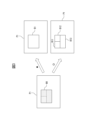
- FIG. 3 is a diagram for explaining an example of a workpiece recognition process in the first example of the position correction device according to the present embodiment.
- FIG. 4 is a flowchart for explaining an example of processing in a second example of a position correction program according to this embodiment.
- FIG. 5 is a diagram for explaining an example of a workpiece recognition process in the second example of the position correction device according to the present embodiment.
- FIG. 6 is a diagram for explaining the shape region of a workpiece in the first and second examples of the position correction device according to this embodiment.
- FIG. 1 is a diagram showing a schematic diagram of an example of a robot system according to this embodiment.
- the robot system 100 includes a robot 1, a robot control device 2, a position correction device 3, and an acquisition unit (measurement unit) 4.
- the robot 1 includes a robot mechanism unit 10, an arm 11, and an end effector (hand unit) 12.
- the robot 1 is configured as, for example, a multi-axis robot, and an end effector 12 is provided at the tip of an arm 11.
- the end effector 12 is a suction device (suction hand), but it goes without saying that this can be changed to various types depending on the object (workpiece) to which the robot system is applied and the work content.
- the robot mechanism unit 10 is for making the robot 1 perform a predetermined operation based on a control command from the robot control device 2. That is, the robot control device 2 receives the output of the position correction device 3, and generates a control command for making the robot 1 perform a predetermined operation based on, for example, a program or teaching data stored in an internal storage device, and outputs it to the robot mechanism unit 10.
- the position correction device 3 is depicted as being independent from the robot control device 2, the position correction device 3 may be configured to be incorporated inside the robot control device 2.
- the acquisition unit 4 is for acquiring two-dimensional images and three-dimensional measurement data (three-dimensional point cloud data) of the area where multiple workpieces (e.g., multiple cardboard boxes) D1 to D9 exist, and includes, for example, two cameras 4a and 4b and a projector 4c.
- the projector 4c projects a predetermined pattern onto the area where the multiple workpieces D1 to D9 exist, and the two cameras 4a and 4b capture an image of the area where the multiple workpieces exist onto which the predetermined pattern is projected by the projector 4c, and measure the three-dimensional shapes of the workpieces D1 to D9.
- the acquisition unit 4 can measure the three-dimensional shape of the areas where the multiple workpieces D1 to D9 exist and acquire three-dimensional measurement data. Furthermore, the acquisition unit 4 can also acquire a two-dimensional image of the areas where the multiple workpieces D1 to D9 exist, for example, by using an image captured by one of the two cameras 4a and 4b.
- the acquisition unit 4 is not limited to the above-mentioned configuration, and may, for example, acquire three-dimensional measurement data of the area where multiple workpieces are present using stereo cameras 4a and 4b, and acquire two-dimensional images of the area where multiple workpieces are present using two-dimensional camera 4c. Furthermore, the acquisition unit 4 may have various other configurations as long as it can acquire two-dimensional images and three-dimensional measurement data of the area where workpieces D1 to D9 are present. In FIG.
- the acquisition unit 4 outputs two-dimensional images and three-dimensional measurement data to the position correction device 3, but the position correction device 3 may, for example, receive and process only image data captured by each of the cameras 4a to 4c of the acquisition unit 4, and internally generate two-dimensional images and three-dimensional measurement data (three-dimensional point cloud data).
- the position correction device 3 performs position correction processing of the workpiece based on the two-dimensional image and three-dimensional measurement data from the acquisition unit 4, or based on the two-dimensional image and three-dimensional measurement data generated from the image data of each camera 4a to 4c from the acquisition unit 4.
- the position correction device 3 can be built into the robot control device 2, instead of being provided as a dedicated position correction device 3.
- the position correction device 3 can be configured as a dedicated workstation provided near the robot control device 2, or a higher-level computer or general-purpose computer provided at a location remote from the robot system 100.
- a general-purpose computer or processor may be used, but faster processing can be achieved by applying a GPGPU (General-Purpose computing on Graphics Processing Units) or a large-scale PC cluster.
- GPGPU General-Purpose computing on Graphics Processing Units
- a large-scale PC cluster may be used, but faster processing can be achieved by applying a GPGPU (General-Purpose computing on Graphics Processing Units) or a large-scale PC cluster.
- the position correction device of this first example corrects and calculates the shape area of the workpiece (object) calculated based on a two-dimensional image using three-dimensional measurement data (three-dimensional point cloud data), and corrects the position, orientation, external size, etc. of the workpiece based on the corrected shape area. Furthermore, the position correction device of this second example corrects and calculates the shape area of the workpiece calculated based on three-dimensional measurement data using the image processing results of the two-dimensional image, and corrects the position, orientation, external size, etc. of the workpiece based on the corrected shape area.
- FIG. 6 is a diagram for explaining the shape area of the workpiece in the first and second examples of the position correction device according to this embodiment.
- shape area of the workpiece refers to, for example, the area indicated by reference character A1 (area of the workpiece D itself) that includes only the workpiece D and does not include the background area around the workpiece D in the two-dimensional image or three-dimensional image (generated from three-dimensional measurement data) P3 output from the acquisition unit 4, as shown in the left diagram of FIG. 6.
- the area includes the workpiece D and its surrounding background area, and is not the area indicated by reference character A2 (area of a predetermined shape) of a predetermined shape.
- the "shape area of the workpiece" in this specification is "area information reflecting the shape/outer shape of the workpiece", and this information can be used to calculate the shape/outer shape of the workpiece.
- FIG. 2 is a flowchart for explaining an example of processing in a first embodiment of the position correction program (position correction device) according to this embodiment
- FIG. 3 is a diagram for explaining an example of work recognition processing in the first embodiment of the position correction device according to this embodiment.
- FIG. 2 when an example of processing in the position correction program of the first embodiment starts (START), in step ST11, two-dimensional images and three-dimensional measurement data of the presence areas of multiple workpieces are acquired. That is, as described with reference to FIG. 1, the acquisition unit 4 acquires two-dimensional images and three-dimensional measurement data (three-dimensional point cloud data) of the presence areas of multiple workpieces (e.g., multiple cardboard boxes) D1 to D9, and outputs them to the position correction device 3.
- multiple workpieces e.g., multiple cardboard boxes
- step ST12 to detect the workpiece based on the two-dimensional image. That is, the position correction device 3 detects the workpiece based on the two-dimensional image from the acquisition unit 4.
- FIG. 3 shows a case where there is almost no difference in the shading or color (hue, brightness, and saturation) of the entire workpiece (object) B0 in a two-dimensional image P1 capturing an area where multiple workpieces are present. That is, for example, if the shading or color of the workpiece B0 is almost the same in the two-dimensional image P1, the position correction device 3 detects the workpiece B0 as a single workpiece (B1) and proceeds to step ST13.
- step ST13 the workpiece detection results are corrected based on the three-dimensional measurement data. Specifically, if the three-dimensional measurement data from the acquisition unit 4 shows that the heights (three-dimensional shapes) of the workpieces B11, B12, and B13 are different, for example, the detection results (for example, the number of detections, the detection position and orientation, the external size, etc.) are corrected to show that the workpiece B0 in the two-dimensional image P1 is not one workpiece B1, but three workpieces B11, B12, and B13.
- the detection results for example, the number of detections, the detection position and orientation, the external size, etc.
- the position correction device 3 corrects the number of detections from one to three so that there are three workpieces B11, B12, and B13 by comparing the erroneous detection result that shows that the workpiece B0 is one workpiece B1 based on the two-dimensional image with the three-dimensional measurement data, and correctly corrects and outputs data such as the detection position and orientation and the external size.
- the two-dimensional image used by the position correction device 3 to detect the workpiece i.e., the two-dimensional image of the area where the multiple workpieces are present acquired by the acquisition unit 4
- the two-dimensional image used by the position correction device 3 to detect the workpiece may be, for example, either a black and white image (grayscale image) or a color image (RGB image).
- the three-dimensional measurement data used by the position correction device 3 to correct the workpiece detection result i.e., the three-dimensional measurement data of the area where the multiple workpieces are present acquired by the acquisition unit 4, may be, for example, data that can acquire information in the height direction.
- step ST14 where the robot's motion is planned
- step ST15 where the robot 1 is controlled to pick up the workpieces. That is, in step ST14, the robot control device 2 plans the motion of the robot 1 so that, assuming that there are three workpieces B11, B12, and B13, and based on the output data of the position correction device 3, such as information on the position and orientation of each workpiece, all workpieces that have been detected/recognized are picked up.
- step ST15 the robot control device 2 outputs a control command to the robot mechanism unit 10, for example, so that the robot 1 picks up the three workpieces B11, B12, and B13 in order, and the robot mechanism unit 10 receives the control command and performs the pick-up operation.
- END an example of the processing in the first example of the position correction program according to this embodiment is ended (END).
- the robot mechanism 10 may move to an incorrect/shifted detection position to attempt to pick up workpiece B1, failing to lift up workpiece B1, or may fail in such a way that the suction pad actually touches the lower right corner of workpiece B11 to lift it up, but then loses balance during subsequent handling and causes workpiece B11 to drop.
- the position correction device 3 of this first embodiment makes it possible to prevent failures in the pick-up operation by correcting the detection results, such as the number of workpieces detected and the detected position and orientation.
- the first example of the position correction program calculates at least the detection position of at least one workpiece based on a two-dimensional image capturing the areas in which multiple workpieces exist, and corrects and outputs the detection position of at least one workpiece based on three-dimensional measurement data measuring the areas in which multiple workpieces exist.
- the position correction device 3 of the first example for example, corrects and calculates the shape area of the workpiece calculated based on the two-dimensional image using three-dimensional measurement data, and corrects and calculates the position, orientation, external size, etc. of the workpiece based on the corrected shape area.
- the position correction device 3 can use the learning results (e.g., a trained model) of image processing or machine learning to calculate the shape area of each of the multiple workpieces (e.g., multiple boxes, cardboard boxes, etc.) shown in the two-dimensional image from the acquisition unit 4.
- the stereo cameras (4a, 4b) of the acquisition unit 4 are used to capture multiple two-dimensional images of the areas in which multiple workpieces are arranged in different arrangements, and three-dimensional measurements are simultaneously performed to obtain three-dimensional point cloud data (three-dimensional measurement data).
- the shape area of each of the workpieces shown in the captured multiple two-dimensional images is taught, and the teaching results and images are generated as training data.
- deep learning is performed using, for example, Fast R-CNN (Region Based Convolutional Neural Networks), Faster R-CNN, Mask R-CNN, etc., to generate a trained model.
- the acquisition unit 4 captures a new two-dimensional image and predicts and calculates the shape area of each of the multiple workpieces captured in the captured image using the trained model.
- the process of generating machine learning learning data and the process of executing machine learning to generate a trained model may be performed by a separate device. In that case, the position correction device 3 receives the trained model data and calculates the shape area of the workpiece.
- various known image processing techniques e.g., pattern matching, edge extraction, etc.
- the position correction device 3 compares the calculation results of the shape area in each of the two-dimensional images of the multiple workpieces with the three-dimensional measurement data (e.g., three-dimensional point cloud data or three-dimensional image) and the two-dimensional image, and uses the difference in three-dimensional position contained in the three-dimensional measurement data to exclude background areas, obstacle areas, areas of adjacent workpieces, etc. that are erroneously included in the calculation results.
- the position correction device 3 also compares the three-dimensional measurement data with the two-dimensional image, calculates features based on the three-dimensional measurement data, corrects the shape area of the workpiece in the two-dimensional image using the calculated features, and corrects and outputs the detection position of the workpiece based on the corrected shape area.
- the center of gravity position of the shape area may be calculated and output as the detection position of the workpiece.
- the robot control device 2 controls the robot 1 (robot mechanism unit 10) based on the corrected detection position from the position correction device 3, and causes the robot 1 to perform the workpiece removal process.
- the position correction device 3 also calculates at least one of a groove, a gap, a step, a three-dimensional plane, and a three-dimensional curved surface as a feature. Furthermore, the position correction device 3 performs correction calculations for at least one of the posture, outer shape, and size of the at least one workpiece, along with the detected position of the at least one workpiece, and outputs the results.
- the background area around the workpiece may also be erroneously recognized as part of the workpiece, or part of the workpiece may be erroneously recognized as the background area.
- the shape area of the workpiece and the background area cannot be correctly distinguished, and a size larger or smaller than the actual size is erroneously detected as the size of the workpiece.
- part of the background area where no work is present may be erroneously recognized as the shape area of the workpiece.
- the shape area of the workpiece is erroneously recognized as the background area, and a workpiece in the background cannot be detected and is not detected.
- the position correction device 3 of this first embodiment therefore uses the three-dimensional position information contained in the three-dimensional measurement data (three-dimensional point cloud data) corresponding to the workpiece shape region and background region on the two-dimensional image to calculate the difference between their three-dimensional positions. If the difference in three-dimensional position between the workpiece shape region and the background region is large, for example exceeding a predetermined threshold, it is determined that the two regions are separate (not regions within the same workpiece), and the workpiece shape region and background region can be correctly distinguished, preventing erroneous recognition (misdetection) of the workpiece shape region and background region, non-detection of the workpiece, and erroneous detection of the background.
- the position correction device 3 of this first embodiment uses the three-dimensional measurement data acquired by the acquisition unit 4 to calculate features such as gaps, grooves, and steps to recognize the gaps between the workpieces, thereby preventing multiple closely spaced workpieces from being erroneously recognized as one.
- the position correction device 3 of the first embodiment uses the three-dimensional measurement data acquired by the acquisition unit 4 to calculate the characteristics of a three-dimensional plane or three-dimensional curved surface, and for example, determines that multiple areas of different colors are actually areas on the same plane or curved surface, thereby preventing one workpiece from being erroneously recognized as two or more workpieces.
- the difference in the three-dimensional positions of the workpiece and the background according to the three-dimensional measurement data can be used to correctly distinguish the shape area of the workpiece from the background area, preventing misrecognition of the workpiece and the background and non-detection of the workpiece.
- the gap (gap, groove, step, etc.) between two workpieces that are close to each other on the two-dimensional image can be recognized using the three-dimensional measurement data, thereby preventing the two workpieces from being misrecognized as one.
- the three-dimensional measurement data confirms that the areas are on the same plane or curved surface, preventing the misrecognition of one workpiece as two or more workpieces.
- FIG. 4 is a flowchart for explaining an example of processing in a second embodiment of the position correction program (position correction device) according to this embodiment
- FIG. 5 is a diagram for explaining an example of work recognition processing in the second embodiment of the position correction device according to this embodiment.
- FIG. 4 when an example of processing in the position correction program of the second embodiment starts (START), in step ST21, three-dimensional measurement data and two-dimensional images of the areas where multiple workpieces exist are acquired. That is, as explained with reference to FIG. 1, the acquisition unit 4 acquires two-dimensional images and three-dimensional measurement data of the areas where multiple workpieces D1 to D9 exist, and outputs them to the position correction device 3.
- step ST22 to detect the workpiece based on the three-dimensional measurement data. That is, the position correction device 3 detects the workpiece based on the three-dimensional measurement data from the acquisition unit 4.
- FIG. 5 shows a case where there is almost no difference in the overall height (three-dimensional shape) of the workpiece (object) C0 in three-dimensional measurement data (e.g., a three-dimensional image generated from three-dimensional point cloud data) P2 capturing an image of the areas in which multiple workpieces exist. That is, if the heights of the workpieces C0 are approximately the same in the three-dimensional measurement data P2, the position correction device 3 detects the workpieces C0 as a single workpiece (C1) and proceeds to step ST23.
- three-dimensional measurement data e.g., a three-dimensional image generated from three-dimensional point cloud data
- step ST23 the detection results of the workpieces are corrected based on the two-dimensional image. Specifically, in the two-dimensional image from the acquisition unit 4, for example, if the shades and colors (hue, brightness, and thickness) of the workpieces C11, C12, and C13 are significantly different, the detection results (for example, the number of detections, the detection position and orientation, the external size, etc.) are corrected to show that the workpiece C0 in the three-dimensional measurement data P2 is not one workpiece C1, but three workpieces C11, C12, and C13.
- the detection results for example, the number of detections, the detection position and orientation, the external size, etc.
- the position correction device 3 compares the detection results in which the workpiece C0 is one workpiece C1 based on the three-dimensional measurement data with the two-dimensional image, corrects the number of detections from one to three so that there are three workpieces C11, C12, and C13, and correctly corrects and outputs data such as the detection position and orientation and external size.
- step ST24 where the robot's motion is planned
- step ST25 where the robot 1 is controlled to pick up the workpiece. That is, in step ST24, the robot control device 2 plans the motion of the robot 1 so that, assuming that there are three workpieces C11, C12, and C13, and based on the output data of the position correction device 3, such as information on the position and orientation of each workpiece, it picks up all of the workpieces that have been detected/recognized.
- step ST25 the robot control device 2 outputs a control command to the robot mechanism unit 10, for example, so that the robot 1 picks up the three workpieces C11, C12, and C13 in order, and the robot mechanism unit 10 receives the control command and performs the pick-up operation.
- END an example of the processing in the second example of the position correction program according to this embodiment is ended (END).
- the robot mechanism 10 may move to an incorrect/shifted detection position to attempt to pick up workpiece C1, resulting in failure to lift up workpiece C1, or the suction pad may come into contact with a position shifted from the actual center of gravity of workpiece C12, lift it up, and then lose balance during subsequent handling, causing workpiece C12 to be dropped.
- the position correction device 3 of the second embodiment makes it possible to prevent failures in the pick-up operation by correcting the detection results, such as the number of detected works and the detected positions and orientations of the works.
- the second example of the position correction program (position correction device) according to this embodiment corrects and calculates the shape area of the workpiece calculated based on the three-dimensional measurement data using the image processing results of the two-dimensional image, and corrects the position, orientation, external size, etc. of the workpiece based on the corrected shape area.
- the position correction device 3 of the second example calculates the detection position of the workpiece based on the three-dimensional measurement data, and corrects the detection position of the workpiece based on the processing results of the two-dimensional image.
- the position correction device 3 at least calculates the detection position of at least one workpiece based on three-dimensional measurement data that measures the presence areas of multiple workpieces, and at least corrects and outputs the detection position of at least one workpiece based on a two-dimensional image that captures the presence areas of the multiple workpieces.
- the position correction device 3 of the second embodiment also calculates the shape area of the workpiece in the three-dimensional measurement data, and corrects and outputs at least one detection position of the workpiece based on the calculated shape area of the workpiece.
- the position correction device 3 may be configured to calculate the shape area of the workpiece in the three-dimensional measurement data by using the learning results of image processing or machine learning.
- the position correction device 3 can also calculate the shape area of the workpiece in the three-dimensional measurement data by performing a matching process, for example, with a three-dimensional CAD (Computer Aided Design) model of the workpiece for the three-dimensional measurement data (e.g., three-dimensional point cloud data).
- CAD Computer Aided Design
- the position correction device 3 of this second embodiment may compare the two-dimensional image with the three-dimensional measurement data, use the difference in pixel values contained in the two-dimensional image to correct the shape area of the workpiece in the three-dimensional measurement data, and correct and output the detection position of the workpiece based on the corrected shape area.
- the position correction device 3 may also compare the two-dimensional image with the three-dimensional measurement data, calculate features based on the two-dimensional image, use the calculated features to correct the shape area of the workpiece in the three-dimensional measurement data, and correct and output the detection position of the workpiece based on the corrected shape area.
- the position correction device 3 of the second embodiment may calculate at least one of the following patterns as features: edges, grooves, gaps, steps, circles, planes, curved surfaces, and feature points.
- the position correction device 3 can also calculate at least one of the posture, shape, and size of at least one workpiece along with the detected position of at least one workpiece.
- the position correction device 3 can also correct and output at least one of the posture, shape, and size of at least one workpiece along with the detected position of at least one workpiece.
- the detection accuracy of the position and orientation of the workpiece can be improved by correcting the detected position and orientation using the image processing results of a two-dimensional image captured by an inexpensive camera.
- This makes it possible to obtain detection results of the position and orientation with a high degree of accuracy equivalent to that of an expensive three-dimensional measuring device with high measurement accuracy, thereby reducing the cost of introducing equipment.
- two-dimensional images and three-dimensional measurement data are acquired within the same area (imaging range: area where multiple workpieces exist) and correction calculations are performed.
- the first and second examples of the position correction program capture two-dimensional images of the areas where multiple workpieces are present, and perform three-dimensional measurements on the same areas to obtain three-dimensional measurement data (e.g., three-dimensional point cloud data). The three-dimensional measurement data is then compared with the two-dimensional image, thereby improving the detection (recognition) accuracy of the position, orientation, external size, etc. of the workpiece.
- the first and second examples of the position correction program according to this embodiment described above can be executed by an arithmetic processing device in the robot control device 2, rather than a dedicated position correction device 3, for example, when the load of the calculation process is small. In this case, the position correction device 3 is incorporated inside the robot control device 2.
- the position correction device 3 can be configured by a dedicated workstation provided near the robot control device 2, or a higher-level computer or general-purpose computer provided in a location remote from the robot system 100. Furthermore, the position correction device 3 may perform calculations by receiving only the learning results (e.g., trained model data) obtained by performing machine learning using another device or service, such as a cloud service that can use a GPU device, without performing machine learning.
- learning results e.g., trained model data
- the position correction program according to the present embodiment described above may be provided by recording it on a computer-readable non-transitory recording medium or a non-volatile semiconductor memory, or may be provided via a wired or wireless connection.
- Examples of computer-readable non-transitory recording media include optical disks such as CD-ROMs (Compact Disc Read Only Memory) and DVD-ROMs, or hard disk devices.
- Examples of non-volatile semiconductor memory include PROMs (Programmable Read Only Memory) and flash memories.
- distribution from a server device may be via a wired or wireless LAN (Local Area Network), or a WAN such as the Internet.
- the position correction device, robot system, and position correction program according to this embodiment make it possible to prevent erroneous detection and non-detection problems, and improve the recognition/detection accuracy of the workpiece (object).
- a position correction device (3) that calculates at least a detection position of at least one workpiece (B0, D) based on a two-dimensional image (P1) capturing an area where a plurality of workpieces (D1 to D9, B0, D) are present, and corrects (B1, B11 to B13) the detection position of at least one workpiece (B0) based on three-dimensional measurement data (P2) capturing the area where the plurality of workpieces (D1 to D9, B0, D) are present, and outputs the corrected position.
- P1 two-dimensional image
- P2 three-dimensional measurement data
- the position correction device (3) calculates a shape area (A1) of the workpiece (B0, D) in the two-dimensional image (P1), and calculates (B1, B11 to B13) the detection position of at least one of the workpieces (B0) based on the calculated shape area (A1) of the workpiece (B0, D).
- the position correction device (3) calculates the shape area (A1) of the workpiece (B0, D) in the two-dimensional image (P1) by utilizing a learning result of machine learning.
- the position correction device (3) performs image processing on the two-dimensional image (P1) to calculate the shape area (A1) of the workpiece (B0, D) in the two-dimensional image (P1).
- the position correction device (3) compares the three-dimensional measurement data (P2) with the two-dimensional image (P1), corrects the shape area (A1) of the workpiece (B0, D) in the two-dimensional image (P1) using a difference in three-dimensional position contained in the three-dimensional measurement data (P2), and corrects (B1, B11 to B13) the detection position of the workpiece (B0) based on the corrected shape area and outputs it.
- the position correction device described in any one of Appendix 2 to Appendix 4.
- the position correction device (3) compares the three-dimensional measurement data (P2) with the two-dimensional image (P1), calculates features based on the three-dimensional measurement data (P2), corrects the shape area of the workpiece (B0, D) in the two-dimensional image (P1) using the calculated features, and corrects and outputs the detection position of the workpiece (B0, D) based on the corrected shape area.
- the position correction device described in any one of Appendix 2 to Appendix 5.
- a position correction device (3) that calculates at least a detection position of at least one work (C0, D) based on three-dimensional measurement data (P2) obtained by measuring the existence areas of a plurality of workpieces (D1 to D9, C0, D), and corrects (C1, C11 to C13) the detection position of at least one workpiece (C0) based on a two-dimensional image (P1) obtained by capturing the existence areas of the plurality of workpieces (D1 to D9, C0, D) and outputs the corrected position.
- P2 three-dimensional measurement data
- P1 to D9 three-dimensional measurement data
- P1 two-dimensional image
- the position correction device (3) calculates a shape area (A1) of the workpiece (C0, D) in the three-dimensional measurement data (P2), and calculates (C1, C11 to C13) the detection position of at least one of the workpieces (C0, D) based on the calculated shape area (A1) of the workpiece (C0, D).
- the position correction device (3) calculates the shape area (A1) of the workpiece (C0, D) in the three-dimensional measurement data (P2) by utilizing a learning result of machine learning.
- the position correction device (3) processes the three-dimensional measurement data (P2) to calculate the shape area (A1) of the workpiece (C0, D) in the three-dimensional measurement data (P2).
- the position correction device (3) compares the two-dimensional image (P1) with the three-dimensional measurement data (P2), corrects the shape area (A1) of the workpiece (C0, D) in the three-dimensional measurement data (P2) using a difference in pixel values contained in the two-dimensional image (P1), and corrects and outputs the detection position of the workpiece (C0, D) based on the corrected shape area (A1).
- the position correction device (3) compares the two-dimensional image (P1) with the three-dimensional measurement data (P2), calculates features based on the two-dimensional image (P1), corrects the shape area (A1) of the workpiece (C0, D) in the three-dimensional measurement data (P2) using the calculated features, and corrects and outputs the detection position of the workpiece (C0, D) based on the corrected shape area (A1).
- the position correction device calculates at least one of an edge, a groove, a gap, a step, a circle, a plane, a curved surface, and a pattern of feature points as the feature.
- the position correction device (3) calculates at least one of the posture, the outer shape, and the size of at least one of the workpieces (B0, C0, D) together with the detected position of at least one of the workpieces (B0, C0, D).
- the position correction device (3) corrects and outputs at least one of the posture, shape, and size of at least one of the workpieces (B0, C0, D) together with the detected position of at least one of the workpieces (B0, C0, D).
- a robot (1) that performs a predetermined task on a workpiece (B0, C0, D);
- An acquisition unit (4) that acquires a two-dimensional image (P1) of an existing area of a plurality of workpieces (D1 to D9, B0, C0, D) and acquires three-dimensional measurement data (P2) of the existing area of the plurality of workpieces (D1 to D9, B0, C0, D);
- a position correction device (3) that calculates at least a detection position of at least one of the workpieces (B0, C0, D) based on the two-dimensional image (P1) and the three-dimensional measurement data (P2) from the acquisition unit (4) and corrects and outputs the detection position of at least one of the workpieces (B0, C0, D);
- a robot control device (2) that receives an output of the position correction device (3) and outputs a control command to the robot (1) to control the robot (1);
- a robot system (100) wherein the position correction device (3) is a position
- Appendix 18 The robot system described in Appendix 17, wherein the robot (1) is controlled to pick up the workpiece (B11 to B13, C11 to C13) at the detection position output by the position correction device (3) based on the control command output from the robot control device (2).
- a processing unit includes: Calculate at least a detection position of at least one of the workpieces (B0, D) based on a two-dimensional image (P1) obtained by capturing an area where the workpieces (D1 to D9, B0, D) are present; A position correction program that executes a process to correct and output the detected position of at least one of the workpieces (B0) based on three-dimensional measurement data (P2) obtained by measuring the existence areas of the plurality of workpieces (D1 to D9, B0, D).
- a processing unit includes: Calculating at least a detection position of at least one of the workpieces (C0, D) based on three-dimensional measurement data (P2) obtained by measuring the presence area of the plurality of workpieces (D1 to D9, C0, D); A position correction program that executes a process to correct (C1, C11 to C13) the detected position of at least one of the workpieces (C0) based on a two-dimensional image (P1) obtained by capturing the presence area of the plurality of workpieces (D1 to D9, C0, D) and output the corrected position.
- Robot 2 Robot control device 3
- Position correction device 4 Acquisition unit (measurement unit) 10
- Robot mechanism 11 Arm 12 End effector (hand) 100
Landscapes
- Engineering & Computer Science (AREA)
- Physics & Mathematics (AREA)
- General Physics & Mathematics (AREA)
- Computer Vision & Pattern Recognition (AREA)
- Theoretical Computer Science (AREA)
- Robotics (AREA)
- Mechanical Engineering (AREA)
- Multimedia (AREA)
- Human Computer Interaction (AREA)
- Image Analysis (AREA)
- Image Processing (AREA)
- Manipulator (AREA)
Priority Applications (5)
| Application Number | Priority Date | Filing Date | Title |
|---|---|---|---|
| CN202380086739.6A CN120380299A (zh) | 2023-02-21 | 2023-02-21 | 位置校正装置、机器人系统以及位置校正程序 |
| JP2025501985A JPWO2024176359A1 (https=) | 2023-02-21 | 2023-02-21 | |
| DE112023005156.9T DE112023005156T5 (de) | 2023-02-21 | 2023-02-21 | Positionskorrekturvorrichtung, robotersystem, und positionskorrekturprogramm |
| PCT/JP2023/006260 WO2024176359A1 (ja) | 2023-02-21 | 2023-02-21 | 位置補正装置、ロボットシステムおよび位置補正プログラム |
| TW113102413A TW202434420A (zh) | 2023-02-21 | 2024-01-22 | 位置補正裝置、機器人系統及位置補正程式 |
Applications Claiming Priority (1)
| Application Number | Priority Date | Filing Date | Title |
|---|---|---|---|
| PCT/JP2023/006260 WO2024176359A1 (ja) | 2023-02-21 | 2023-02-21 | 位置補正装置、ロボットシステムおよび位置補正プログラム |
Publications (1)
| Publication Number | Publication Date |
|---|---|
| WO2024176359A1 true WO2024176359A1 (ja) | 2024-08-29 |
Family
ID=92500421
Family Applications (1)
| Application Number | Title | Priority Date | Filing Date |
|---|---|---|---|
| PCT/JP2023/006260 Ceased WO2024176359A1 (ja) | 2023-02-21 | 2023-02-21 | 位置補正装置、ロボットシステムおよび位置補正プログラム |
Country Status (5)
| Country | Link |
|---|---|
| JP (1) | JPWO2024176359A1 (https=) |
| CN (1) | CN120380299A (https=) |
| DE (1) | DE112023005156T5 (https=) |
| TW (1) | TW202434420A (https=) |
| WO (1) | WO2024176359A1 (https=) |
Citations (4)
| Publication number | Priority date | Publication date | Assignee | Title |
|---|---|---|---|---|
| JP2010247959A (ja) * | 2009-04-16 | 2010-11-04 | Ihi Corp | 箱状ワーク認識装置および方法 |
| CN111783529A (zh) * | 2019-07-26 | 2020-10-16 | 牧今科技 | 基于边缘和多维拐角的检测后改善 |
| JP2020537775A (ja) * | 2018-10-30 | 2020-12-24 | 株式会社Mujin | 自動パッケージ登録機構および自動検出パイプラインを備えたロボットシステム |
| WO2021177239A1 (ja) * | 2020-03-05 | 2021-09-10 | ファナック株式会社 | 取り出しシステム及び方法 |
-
2023
- 2023-02-21 DE DE112023005156.9T patent/DE112023005156T5/de active Pending
- 2023-02-21 WO PCT/JP2023/006260 patent/WO2024176359A1/ja not_active Ceased
- 2023-02-21 JP JP2025501985A patent/JPWO2024176359A1/ja active Pending
- 2023-02-21 CN CN202380086739.6A patent/CN120380299A/zh active Pending
-
2024
- 2024-01-22 TW TW113102413A patent/TW202434420A/zh unknown
Patent Citations (4)
| Publication number | Priority date | Publication date | Assignee | Title |
|---|---|---|---|---|
| JP2010247959A (ja) * | 2009-04-16 | 2010-11-04 | Ihi Corp | 箱状ワーク認識装置および方法 |
| JP2020537775A (ja) * | 2018-10-30 | 2020-12-24 | 株式会社Mujin | 自動パッケージ登録機構および自動検出パイプラインを備えたロボットシステム |
| CN111783529A (zh) * | 2019-07-26 | 2020-10-16 | 牧今科技 | 基于边缘和多维拐角的检测后改善 |
| WO2021177239A1 (ja) * | 2020-03-05 | 2021-09-10 | ファナック株式会社 | 取り出しシステム及び方法 |
Also Published As
| Publication number | Publication date |
|---|---|
| CN120380299A (zh) | 2025-07-25 |
| TW202434420A (zh) | 2024-09-01 |
| JPWO2024176359A1 (https=) | 2024-08-29 |
| DE112023005156T5 (de) | 2025-10-30 |
Similar Documents
| Publication | Publication Date | Title |
|---|---|---|
| US11724400B2 (en) | Information processing apparatus for determining interference between object and grasping unit, information processing method, and storage medium | |
| Xiao et al. | An adaptive feature extraction algorithm for multiple typical seam tracking based on vision sensor in robotic arc welding | |
| CN108369650B (zh) | 标识校准图案的可能特征点的方法 | |
| CN115194751B (zh) | 机器人系统、控制方法、图像处理装置及方法和产品制造方法 | |
| US20160279791A1 (en) | Information processing apparatus, information processing method, and storage medium | |
| JP6172432B2 (ja) | 被写体識別装置、被写体識別方法および被写体識別プログラム | |
| JP7191352B2 (ja) | 物体検出を実施するための方法および計算システム | |
| CN115375610A (zh) | 检测方法及装置、检测设备和存储介质 | |
| JP2009288917A (ja) | 情報処理装置、情報処理方法、およびプログラム | |
| US20150063637A1 (en) | Image recognition method and robot | |
| JP5403367B2 (ja) | 物体形状評価装置 | |
| TW202046248A (zh) | 圖型匹配方法 | |
| JP2021071420A (ja) | 情報処理装置、情報処理方法、プログラム、システム、物品の製造方法、計測装置及び計測方法 | |
| WO2024176359A1 (ja) | 位置補正装置、ロボットシステムおよび位置補正プログラム | |
| JP6237122B2 (ja) | ロボット、画像処理方法及びロボットシステム | |
| CN116033999A (zh) | 机器人系统以及控制方法 | |
| Fu et al. | Pose estimation method combining the PNP algorithm and contour depth extraction for peg-in-hole assembly | |
| Tellaeche et al. | 6DOF pose estimation of objects for robotic manipulation. A review of different options | |
| JP7323061B2 (ja) | エレベーターの3次元データの処理装置 | |
| JP7614358B2 (ja) | 画像処理装置及びコンピュータ読み取り可能な記憶媒体 | |
| Araújo et al. | Machine vision for industrial robotic manipulator using raspberry Pi | |
| TW202040510A (zh) | 影像匹配判定方法、影像匹配判定裝置、及記錄了用於使電腦執行影像匹配判定方法的程式的電腦可讀取之記錄媒體 | |
| CN117351213B (zh) | 基于3d视觉的箱体分割定位方法及系统 | |
| US20250196351A1 (en) | Robot system | |
| CN115937273A (zh) | 图像对位方法、系统、记录媒体、以及计算机程序产品 |
Legal Events
| Date | Code | Title | Description |
|---|---|---|---|
| 121 | Ep: the epo has been informed by wipo that ep was designated in this application |
Ref document number: 23924013 Country of ref document: EP Kind code of ref document: A1 |
|
| WWE | Wipo information: entry into national phase |
Ref document number: 2025501985 Country of ref document: JP |
|
| WWE | Wipo information: entry into national phase |
Ref document number: 202380086739.6 Country of ref document: CN |
|
| WWP | Wipo information: published in national office |
Ref document number: 202380086739.6 Country of ref document: CN |
|
| WWE | Wipo information: entry into national phase |
Ref document number: 112023005156 Country of ref document: DE |
|
| WWP | Wipo information: published in national office |
Ref document number: 112023005156 Country of ref document: DE |
|
| 122 | Ep: pct application non-entry in european phase |
Ref document number: 23924013 Country of ref document: EP Kind code of ref document: A1 |