WO2024176292A1 - 管理システム、管理方法、及び、記録媒体 - Google Patents
管理システム、管理方法、及び、記録媒体 Download PDFInfo
- Publication number
- WO2024176292A1 WO2024176292A1 PCT/JP2023/005956 JP2023005956W WO2024176292A1 WO 2024176292 A1 WO2024176292 A1 WO 2024176292A1 JP 2023005956 W JP2023005956 W JP 2023005956W WO 2024176292 A1 WO2024176292 A1 WO 2024176292A1
- Authority
- WO
- WIPO (PCT)
- Prior art keywords
- information
- location
- management
- mobile object
- reading
- Prior art date
- Legal status (The legal status is an assumption and is not a legal conclusion. Google has not performed a legal analysis and makes no representation as to the accuracy of the status listed.)
- Ceased
Links
Images




Classifications
-
- G—PHYSICS
- G06—COMPUTING OR CALCULATING; COUNTING
- G06Q—INFORMATION AND COMMUNICATION TECHNOLOGY [ICT] SPECIALLY ADAPTED FOR ADMINISTRATIVE, COMMERCIAL, FINANCIAL, MANAGERIAL OR SUPERVISORY PURPOSES; SYSTEMS OR METHODS SPECIALLY ADAPTED FOR ADMINISTRATIVE, COMMERCIAL, FINANCIAL, MANAGERIAL OR SUPERVISORY PURPOSES, NOT OTHERWISE PROVIDED FOR
- G06Q30/00—Commerce
- G06Q30/06—Buying, selling or leasing transactions
- G06Q30/0645—Rental transactions; Leasing transactions
Definitions
- This disclosure relates to a management system, a management method, and a recording medium.
- Patent Document 1 discloses technology that allows a rental object to be rented to a user using a mobile terminal of the user to whom the rental object is rented and a short-range wireless communication unit installed in the rental object.
- One example of the objectives of this disclosure is to provide a management system that can confirm that an item has been returned to the correct location without placing a burden on the user.
- the management system includes a mobile object equipped with a medium that holds the unique information of the mobile object itself, and a reading device installed at a management location of the mobile object, the reading device having a reading means for reading the unique information and a transmitting means for transmitting the unique information and information on the management location of the reading device.
- the management system in one aspect of the present disclosure is provided at the management location of a mobile body, and includes a medium that holds information about the management location, and a reading device, and the reading device includes a reading means for reading the information about the management location, and a transmitting means for transmitting the information about the management location and unique information about the user or the mobile body itself.
- a computer reads the unique information of the mobile object itself that is stored on a medium provided in the mobile object, and transmits the unique information and information on the management location of the computer.
- a computer reads information about a management location stored on a medium provided in the management location of a mobile object, and transmits the information about the management location and unique information of the user or the mobile object itself.
- the recording medium stores a program that causes a computer to execute a process of reading the unique information of the mobile object itself, which is held in a medium provided in the mobile object, and transmitting the unique information and information on the management location of the reading device that read the unique information.
- the recording medium stores a program that causes a computer to execute a process of reading information about a management location held by a medium provided in the management location of a mobile object, and transmitting the information about the management location and unique information of the user or the mobile object itself.
- This disclosure provides a management system that can confirm that an item has been returned to the correct location without placing a burden on the user.
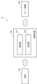
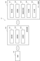
- FIG. 1 is a block diagram showing a management system according to the first embodiment.
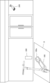
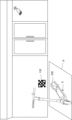
- FIG. 2 is a diagram for explaining a management location in the first embodiment.
- FIG. 3 is a diagram showing a hardware configuration in which the reading device according to the first embodiment is realized by a computer device and its peripheral devices.
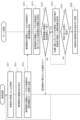
- FIG. 4 is a flowchart showing the operation of the management system in the first embodiment.
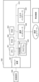
- FIG. 5 is a block diagram showing a management system according to a modified example of the first embodiment.
- FIG. 6 is a flowchart showing the operation of the management system in the modified example of the first embodiment.
- FIG. 7 is a block diagram showing a management system according to the second embodiment.
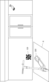
- FIG. 8 is a diagram for explaining a management location in the second embodiment.
- FIG. 9 is a flowchart showing the operation of the management system in the second embodiment.
- FIG. 10 is a block diagram showing a management system according to a modified example of the second embodiment.
- FIG. 11 is a diagram for explaining a management location in a modified example of the second embodiment.
- FIG. 12 is a flowchart showing the operation of the management system in the modified example of the second embodiment.
- Fig. 1 is a block diagram showing a management system 10 according to the present embodiment.
- the management system 10 includes a mobile object 100 equipped with a medium for storing unique information of the mobile object itself, a reading device 200, and a server device 300.
- the management system 10 is a system for checking whether a rented mobile object has been returned at a management location such as an unmanned port installed within a rental service area of the mobile object.
- the mobile object is a mobile object for one person, and includes bicycles, motorized bicycles, motorcycles, electric kick scooters, and electric wheelchairs.
- the explanation is mainly given using an electric kick scooter as an example, but the invention of this disclosure is not limited to electric kick scooters.
- the server device 300 is a server managed by a company that provides a rental service for mobile objects, and receives information from the reading device 200 and manages the return status of each mobile object based on the received information. For example, the server device 300 manages a rental mobile object as "not available for rental" and a non-rented mobile object as "available for rental". When a user reserves a rental mobile object on an application program for using the rental service, the status of the mobile object 100 stored in the server device 300 becomes "not available for rental". On the other hand, when the rented mobile object is returned, the status of the mobile object becomes "available for rental". The server device 300 also stores information on the return location of the rented mobile object in association with the ID of the mobile object. The server device 300 may output information indicating the rental status and return status of the mobile object to a user terminal carried by the user.
- the mobile object 100 is provided with a medium such as an RFID (Radio frequency identification) tag, Bluetooth (registered trademark) tag, or sticker, and these media hold unique information such as an ID for identifying the mobile object 100.
- a medium such as an RFID (Radio frequency identification) tag, Bluetooth (registered trademark) tag, or sticker
- unique information such as an ID for identifying the mobile object 100.
- the medium is an RFID tag or Bluetooth tag
- the unique information of the mobile object itself is stored in these tags.
- the medium is a sticker, a two-dimensional code with the unique information of the mobile object 100 embedded therein is printed on it.
- FIG. 2 is a diagram for explaining the management location in the first embodiment.
- the example in FIG. 2 shows a case where a return port is installed in front of a store.
- a mobile object 100 has a medium 100a at its rear, and the medium 100a holds unique information.
- the position of the medium 100a is not limited to the example in FIG. 2.
- the reading device 200 is installed on a wall of the store with the reading unit 201 facing outward, and if the reading device 200 is a camera, it may be configured as a security camera.
- FIG. 3 is a diagram showing an example of a hardware configuration in which the reading device 200 in the first embodiment of the present disclosure is realized by a computer device 500 including a processor.
- the reading device 200 includes a CPU (Central Processing Unit) 501, memories such as a ROM (Read Only Memory) 502 and a RAM (Random Access Memory) 503, a storage device 505 such as a hard disk for storing a program 504, a communication interface 508 for network connection, and an input/output interface 509 for inputting and outputting data.
- the reading device 200 is connected to each component via a bus 510.
- the CPU 501 runs an operating system to control the entire reading device 200 according to the first embodiment of the present invention.
- the CPU 501 also reads programs and data from a recording medium 506 mounted in a drive device 507 or the like, into memory.
- the CPU 501 also functions as the reading unit 201 and transmission unit 202 in the first embodiment, or as a part of these, and executes the processes or commands in the flowchart shown in FIG. 4, which will be described later, based on the programs.
- the recording medium 506 is, for example, an optical disk, a flexible disk, a magneto-optical disk, an external hard disk, or a semiconductor memory.
- the semiconductor memory which is part of the recording medium, is a non-volatile storage device in which the program is recorded.
- the program may also be downloaded from an external computer (not shown) that is connected to a communication network.
- the first embodiment shown in FIG. 1 is realized by the computer hardware shown in FIG. 3.
- the means for realizing each part of the reading device 200 in FIG. 1 is not limited to the configuration described above.
- the reading device 200 may be realized by a single physically combined device, or may be realized by a system consisting of two or more physically separated devices connected by wire or wirelessly.
- the reading device 200 comprises a reading unit 201 that reads the unique information of the mobile object 100 itself that is held on a medium provided in the mobile object 100, and a transmission unit 202 that transmits the read unique information.
- the reading unit 201 is provided with means capable of reading the unique information of the mobile object 100, and is composed of an RFID reading means, a Bluetooth tag reading means, a camera, etc.
- the transmission unit 202 transmits the read unique information to the server device 300.
- FIG. 4 is a flowchart showing an overview of the operation of the management system 10 in the first embodiment.
- the processing according to this flowchart may be executed based on program control by the processor described above.
- the processing according to this flowchart is started, for example, when an operation is performed on the reading unit 201 to read the unique information of the mobile object itself.
- the reading unit 201 reads the unique information of the mobile object itself (step S101).
- the transmission unit 202 transmits the unique information and information on the management location of the reading device to the server device 300 (step S102). With this, the reading device 200 ends the process.
- the transmission unit 202 transmits the unique information of the mobile object itself and the information of the management location of the reading device to the server device 300.
- the server device 300 can verify that the mobile object has been returned to the correct location by comparing the management location information with the return location information associated with the mobile object to be returned, without imposing a burden on the user.
- Fig. 5 is a block diagram showing the configuration of the management system 11 in a modified example of the first embodiment.
- the reading device 210 includes a detection unit 211, a reading unit 212, and a transmission unit 213.
- the server device 310 includes a collation unit 311, a transmission unit 312, an image acquisition unit 313, a determination unit 314, and an output unit 315.
- the configurations of the reading unit 212 and the transmission unit 213 are similar to those of the reading unit 201 and the transmission unit 202 in the first embodiment.
- the server device 310 stores unique information of the mobile object 110 to be returned in association with information on the return location.
- the detection unit 211 in the reading device 210 detects that the mobile object has stopped.
- the detection unit 211 detects that the mobile object 110 has stopped using a known method, for example, an infrared sensor detects that the mobile object 110 has stopped at a specified position in the management location.
- the detection unit 211 detects that the mobile object 110 has stopped, it outputs that information to the reading unit 212.
- the reading unit 212 reads the individual information of the mobile object.
- the method of reading the individual information by the reading unit 212 is the same as in the first embodiment.
- the matching unit 311 in the server device 310 matches the management location information received from the reading device 210 with the return location information linked to the mobile object. If the management location information and the return location information match, the matching unit 311 outputs the information to the reading device 210 via the transmission unit 312 and also outputs the information to the image acquisition unit 313. On the other hand, if the management location information and the return location information do not match, the matching unit 311 transmits the information to the reading device 210 via the transmission unit 312.
- the image acquisition unit 313 controls a camera provided in the store to acquire an image of the moving object to be returned.
- the image acquisition unit 313 in this embodiment may be provided on the reading device 210 side. That is, when the reading device 210 receives information from the server device 310 that the return location matches, a component equivalent to the image acquisition unit 313 provided in the reading device 210 may control the camera in the store.
- the image acquisition unit 313 outputs the acquired image to the determination unit 314.
- the determination unit 314 determines whether the mobile object to be returned has been returned to the specified location based on the acquired captured image.
- the designated location refers to, for example, the designated location of a return port such as the frame R in FIG. 2.
- the determination unit 314 determines whether the mobile object has been returned to the specified location by known image analysis.
- the determination unit 314 determines that the mobile object has been returned to the designated location, it changes the management status of the mobile object stored in the server device 310 to "available for loan.” On the other hand, if the determination unit 314 determines that the mobile object has not been returned to the designated location, after a predetermined time has elapsed, the image acquisition unit 313 again controls the camera installed in the store to acquire an image of the mobile object to be returned, and the determination unit 314 again determines whether the mobile object has been returned to the designated location.
- the output unit 315 outputs the return result to the user based on the result of the determination. If the return location is different, the output unit 315 notifies the user terminal of that information. In other words, if the comparison unit 311 determines that the management location information and the preset return location are different, a screen showing the determination result is output to the user terminal, etc. In this case, the output unit 315 may display map information showing the current location and the location of the return location.
- the output unit 315 also outputs the result of the return of the moving object to the specified location by the determination unit 314. That is, when the output unit 315 receives a result from the determination unit 314 that the moving object has been returned to the specified location, it outputs a screen indicating that the return has been completed to the user terminal. On the other hand, when the output unit 315 receives a result from the determination unit 314 that the moving object has not been returned to the specified location, it outputs a screen to the user terminal prompting the user to return the moving object to the specified location.
- the output unit 315 may output the return result to a device other than the user terminal. For example, the output unit 315 may output the return result to the reading device 210 or a display device provided on the moving object.
- FIG. 6 is a flowchart showing an overview of the operation of the management system 10 in a modified example of the first embodiment. Note that the processing according to this flowchart may be executed based on program control by the processor described above.
- the detection unit 211 in the reading device 210 detects that the moving object has stopped (step S111).
- the reading unit 212 reads the unique information held by the medium provided in the moving object (step S112).
- the transmission unit 213 transmits the unique information and information on the management location of the reading device to the server device 310 (step S113).
- the server device 310 receives the unique information and the management location information of the reading device (step S114).
- the matching unit 311 matches the management location information with the return location information linked to the mobile object (step S115). If the matching unit 311 determines that the management location does not match the return location (step S116; NO), it notifies the reading device 210 via the transmission unit 312 that the return location is different (step S117). In this case, the management system 11 repeats the flow of steps S111 to S116 until the management location received from the reading device 210 matches the return location.
- the image acquisition unit 313 controls a camera installed in the store to acquire a captured image of the mobile object to be returned (step S118).
- the determination unit 314 determines that the mobile object to be returned has been returned to the designated location based on the captured image (step S119; YES)
- it changes the status of the mobile object to "available for loan" step S120.
- the determination unit 314 determines that the mobile object to be returned has not been returned to the designated location (step S119; NO)
- the management system 11 may repeat S118 to S119 after receiving information from the user terminal indicating that the mobile object has been returned to the designated location. With this, the management system 11 ends the management process.
- the reading unit 212 reads the unique information held by the medium provided in the mobile object. This automatically starts the procedure for returning the mobile object without any operation by the user.
- the image acquisition unit 313 controls a camera provided in the store to acquire an image of the mobile object to be returned, and the determination unit 314 determines whether the mobile object to be returned has been returned to the specified location. This allows the user to check the return status of the mobile object without sending an image of the mobile object to be returned to the server device 310. Therefore, it is possible to confirm that the mobile object has been returned to the specified location without imposing a burden on the user.
- FIG. 7 is a block diagram showing the management system 12 in the second embodiment.
- FIG. 8 is a diagram for explaining the management location in the second embodiment.
- the functions of the management system 12 can be realized not only by hardware but also by a computer device and software based on program control.
- the management system 12 in this embodiment includes a medium 120 that holds information about the management location of the mobile object, a reading device 220, and a server device 320.
- the medium 120 is composed of an RFID tag, Bluetooth tag, sticker, or the like, and the information about the management location is held in these media.
- the medium 120 is provided on the ground, a wall, or the like of the management location.
- the medium 120 may be attached to a wall of a store as shown in FIG. 8.
- the reading device 220 is composed of a user terminal such as a tablet or smartphone that is carried by the user.
- the reading device 220 includes a reading unit 221 and a transmission unit 222.
- the reading unit 221 reads the management location information stored in the medium 120.
- the reading unit 221 is not limited to any means capable of reading the management location information, and may be, for example, a camera.
- the transmission unit 222 transmits the management location information and the unique information of the user or the mobile object itself to the server device 320, for example, through an application program installed on the user terminal.
- the transmission unit 222 transmits the unique information of the user or the mobile object itself recorded in the application program to the server device 320.
- FIG. 9 is a flowchart showing an overview of the operation of the management system 12 in the second embodiment.
- the processing according to this flowchart may be executed based on program control by the processor described above.
- the processing according to this flowchart is triggered, for example, by an operation being performed on the reading unit 221 to read information about the management location.
- the reading unit 221 reads the management location information held by the medium 120 (step S201).
- the transmission unit 222 transmits the management location information and the unique information of the user or the mobile object itself to the server device 320 (step S202). With this, the reading device 220 ends the process.
- the transmission unit 222 transmits the management location information and the unique information of the user or the mobile object itself to the server device 320.
- the server device 320 can verify the management location information with the return location information linked to the unique information of the user or the mobile object itself, thereby confirming that the item has been returned to the correct location without placing a burden on the user.
- the user's own user terminal can be used as the reading device 220, the service provider does not need to prepare a separate reading device.
- FIG. 10 is a block diagram showing the management system 13 in a modified example of the second embodiment.
- FIG. 11 is a diagram for explaining the management location in the modified example of the second embodiment.
- the reading device 230 includes a detection unit 231, a reading unit 232, and a transmission unit 233.
- the server device 330 includes a collation unit 331, a transmission unit 332, an image acquisition unit 333, a determination unit 334, and an output unit 335.
- the configurations of the reading unit 232 and the transmission unit 233 are similar to those of the reading unit 221 and the transmission unit 222 in the second embodiment.
- the server device 330 stores the unique information of the moving object or the user to be returned in association with the information of the return location.
- the reading device 230 is provided on the moving body.
- the location where the reading device 230 is installed is not particularly limited, and as shown in FIG. 11, it may be installed near the rear wheel fender of the moving body.
- the detection unit 231 in the reading device 230 detects that the moving body has stopped by a known method. For example, the detection unit 231 detects that the stand S of the moving body has been turned downward by a sensor, or that the key of the moving body has been locked. However, these are only examples of detecting that the moving body has stopped, and the detection unit 231 may detect that the moving body has stopped by other methods.
- the detection unit 231 may detect that the moving body has stopped only when it is a predetermined distance from a pre-specified return location or within a predetermined time until a pre-specified return time. In this case, it is possible to reduce the frequency of erroneous reading by the reading unit 232 when the moving body stops before returning to the return location.
- the detection unit 231 When the detection unit 231 detects that the mobile body has stopped, it outputs that information to the reading unit 232.
- the reading unit 232 receives information indicating that the mobile body has stopped from the detection unit 231, it reads the management location information.
- the method of reading the management location information by the reading unit 232 and the method of transmitting the management location information and the unique information of the user or the mobile body itself by the transmission unit 233 are the same as in the second embodiment.
- the matching unit 331 in the server device 330 matches the management location information received from the reading device 230 with the return location information linked to the unique information of the user or the mobile object itself. If the management location information and the return location information match, the matching unit 311 outputs the information to the reading device 230 via the transmission unit 332 and also outputs the information to the image acquisition unit 333. On the other hand, if the unique information of the user or the mobile object itself and the return location information do not match, the matching unit 331 transmits the information to the reading device 230 via the transmission unit 332.
- the method of acquiring a photographed image of a moving object by the image acquisition unit 333, the method of determining whether to return the moving object to a specified position by the determination unit 334, and the method of output by the output unit 335 are similar to the operations of the image acquisition unit 313, the determination unit 314, and the output unit 315 in the modified example of the first embodiment.
- FIG. 12 is a flowchart showing an overview of the operation of the management system 13 in a modified example of the second embodiment. Note that the processing according to this flowchart may be executed based on program control by the processor described above.
- the detection unit 231 of the reading device 230 provided in the mobile object detects that the mobile object has stopped (step S211).
- the reading unit 232 reads the information on the management location of the mobile object stored in a medium provided in the management location (step S212).
- the transmission unit 233 transmits the information on the management location and the unique information of the user or the mobile object itself to the server device 330 (step S213).
- the server device 330 receives the management location information and the unique information of the user or mobile object itself (step S214).
- the matching unit 331 matches the management location information with the return location information linked to the user or mobile object (step S215). If the management location does not match the return location (step S216; NO), the matching unit 331 notifies the reading device 230 via the transmission unit 332 that the return location is different (step S217). In this case, the management system 13 repeats the flow of steps S211 to S216 until the management location information received from the reading device 230 matches the return location.
- the image acquisition unit 333 controls a camera installed in the store to acquire a captured image of the mobile object to be returned (step S218).
- the determination unit 314 determines based on the captured image that the mobile object to be returned has been returned to the specified location (step S219; YES)
- it changes the management status of the mobile object to "available for loan" step S220.
- the determination unit 314 determines that the mobile object to be returned has not been returned to the specified location (step S219; NO)
- the reading unit 232 of the management system 13 reads information about the management location. This automatically starts the procedure for returning the mobile object without any operation by the user. Also, in the modified version of the second embodiment, when the management location matches the return location, the image acquisition unit 333 controls a camera installed in the store to acquire an image of the mobile object to be returned, and the determination unit 334 determines whether the mobile object to be returned has been returned to the specified location. This allows the user to check the return status of the mobile object without sending an image of the mobile object to be returned to the server device 330. Therefore, it is possible to confirm that the mobile object has been returned to the specified location without imposing a burden on the user.
- the system includes a mobile object having a medium for storing unique information of the mobile object itself, and a reading device installed at a management location of the mobile object,
- the reading device is A reading means for reading the unique information; a transmitting means for transmitting the unique information and information on a management location of the reading device.
- the system is provided at a management location of a mobile body, and includes a medium for storing information on the management location and a reading device;
- the reading device has a reading means for reading the information of the management location;
- a management system comprising: a transmission means for transmitting the information on the management location and unique information of the user or the mobile object itself.
- a detection means for detecting that the moving body has stopped is further provided, The management system according to claim 4, wherein the reading means reads information about the management location where the mobile object is stopped when it detects that the mobile object has stopped.
- Appendix 6 The management system described in Appendix 5, wherein the detection means detects that the mobile object has stopped when it is a predetermined distance from a pre-designated return location or within a predetermined time until a pre-designated return time.
- the management system further includes a server device that receives information about the management location, the server device has a checking means for checking whether the information on the management location matches a preset return location; an image acquisition means for controlling a surveillance camera at the management location to acquire an image of the moving object to be returned when the information of the management location matches a preset return location; A determination means for determining whether the moving object has been returned to a designated position; and an output means for outputting the determined result.
Landscapes
- Business, Economics & Management (AREA)
- Accounting & Taxation (AREA)
- Finance (AREA)
- Development Economics (AREA)
- Economics (AREA)
- Marketing (AREA)
- Strategic Management (AREA)
- Physics & Mathematics (AREA)
- General Business, Economics & Management (AREA)
- General Physics & Mathematics (AREA)
- Engineering & Computer Science (AREA)
- Theoretical Computer Science (AREA)
- Management, Administration, Business Operations System, And Electronic Commerce (AREA)
Abstract
Description
図1は、本実施形態における管理システム10を示すブロック図である。図1に示すように、管理システム10は、移動体自身の固有情報を保持する媒体を備えた移動体100と読取装置200とサーバ装置300を含む。管理システム10は、移動体のレンタルサービス提供範囲に設置された無人ポート等の管理場所において、貸し出された移動体が返却されたかを確認するためのシステムである。
図5は、第一の実施形態の変形例における管理システム11の構成を示すブロック図である。図5を参照すると、読取装置210は、検知部211と、読取部212と、送信部213とを備える。また、サーバ装置310が照合部311と送信部312と画像取得部313と判定部314と出力部315を備える。本実施形態において、読取部212と送信部213の構成は、第一の実施形態の読取部201と送信部202と同様である。また、本実施形態において、サーバ装置310は、返却予定の移動体110の固有情報と返却場所の情報とを紐づけて格納している。
次に、本開示の第二の実施形態について図面を参照して詳細に説明する。以下、本実施形態の説明が不明確にならない範囲で、前述の説明と重複する内容については説明を省略する。
図10は、第二の実施形態の変形例における管理システム13を示すブロック図である。図11は、第二の実施形態の変形例における管理場所を説明するための図である。図10を参照すると、読取装置230は、検知部231と、読取部232と、送信部233とを備える。また、サーバ装置330が照合部331と送信部332と画像取得部333と判定部334と出力部335を備える。本実施形態において、読取部232と送信部233の構成は、第二の実施形態の読取部221と送信部222と同様である。また、本実施形態において、サーバ装置330は、返却予定の移動体又はユーザの固有情報と返却場所の情報とを紐づけて格納している。
移動体自身の固有情報を保持する媒体を備えた移動体と、移動体の管理場所に設置された読取装置とを有し、
前記読取装置は、
前記固有情報を読み取る、読取手段と、
前記固有情報と当該読取装置の管理場所の情報とを送信する、送信手段と、を備える、管理システム。
前記移動体が前記管理場所に停車したことを検知する、検知手段を更に備え、
前記読取手段は、前記移動体が停車したことを検知したときに、当該移動体自身の固有情報を読み取る、付記1に記載の管理システム。
移動体の管理場所に備えられ、当該管理場所の情報を保持する媒体と、読取装置と、を有し、
前記読取装置は、前記管理場所の情報を読み取る、読取手段と、
前記管理場所の情報とユーザ又は移動体自身の固有情報とを送信する、送信手段と、を備える、管理システム。
前記読取装置は、前記移動体に設けられる、付記3に記載の管理システム。
前記移動体が停車したことを検知する、検知手段を更に備え、
前記読取手段は、前記移動体が停車したことを検知したときに、当該移動体が停車した前記管理場所の情報を読み取る、付記4に記載の管理システム。
前記検知手段は、予め指定された返却場所から所定距離である又は予め指定された返却時間まで所定時間内である場合に前記移動体が停車したことを検知する、付記5に記載の管理システム。
前記管理システムは、前記管理場所の情報を受信するサーバ装置を更に含み、
前記サーバ装置は、前記管理場所の情報が予め設定された返却場所と一致するか否かを照合する、照合手段と、
前記管理場所の情報が予め設定された返却場所と一致した場合、前記管理場所の監視カメラを制御して返却対象の移動体を撮影した撮影画像を取得する、画像取得手段と、
前記移動体が指定された位置に返却されているか否かを判定する、判定手段と、
前記判定された結果を出力する、出力手段と、を備える、付記1~5に記載の管理システム。
前記出力手段は、前記管理場所の情報が予め設定された返却場所と一致しない場合に、前記返却場所の位置を示す情報を出力する、付記7に記載の管理システム。
コンピュータが、
移動体に備えられた媒体が保持する、移動体自身の固有情報を読み取り、
前記固有情報と当該コンピュータの管理場所の情報とを送信する、管理方法。
コンピュータが、
移動体の管理場所に備えられた媒体が保持する、当該管理場所の情報を読み取り、
前記管理場所の情報とユーザ又は移動体自身の固有情報とを送信する、管理方法。
移動体に備えられた媒体が保持する、移動体自身の固有情報を読み取り、
前記固有情報と当該固有情報を読み取った読取装置の管理場所の情報とを送信する処理をコンピュータに実行させるプログラムを格納した記録媒体。
移動体の管理場所に備えられた媒体に格納された、当該管理場所の情報を読み取り、
前記管理場所の情報とユーザ又は移動体自身の固有情報とを送信する処理をコンピュータに実行させるプログラムを格納した記録媒体。
100、110 移動体
120、130 媒体
200、210、220、230 読取装置
201、212、221、232 読取部
202、213、222、233 送信部
211、231 検知部
300、310、320、330 サーバ装置
311、331 照合部
312、332 送信部
313、333 画像取得部
314、334 判定部
315、335 出力部
500 コンピュータ装置
501 CPU
502 ROM
503 RAM
504 プログラム
505 記憶装置
506 記録媒体
507 ドライブ装置
508 通信インタフェース
509 入出力インタフェース
510 バス
Claims (12)
- 移動体自身の固有情報を保持する媒体を備えた移動体と、移動体の管理場所に設置された読取装置とを有し、
前記読取装置は、
前記固有情報を読み取る、読取手段と、
前記固有情報と当該読取装置の管理場所の情報とを送信する、送信手段と、を備える、管理システム。 - 前記移動体が前記管理場所に停車したことを検知する、検知手段を更に備え、
前記読取手段は、前記移動体が停車したことを検知したときに、当該移動体自身の固有情報を読み取る、請求項1に記載の管理システム。 - 移動体の管理場所に備えられ、当該管理場所の情報を保持する媒体と、読取装置と、を有し、
前記読取装置は、前記管理場所の情報を読み取る、読取手段と、
前記管理場所の情報とユーザ又は移動体自身の固有情報とを送信する、送信手段と、を備える、管理システム。 - 前記読取装置は、前記移動体に設けられる、請求項3に記載の管理システム。
- 前記移動体が停車したことを検知する、検知手段を更に備え、
前記読取手段は、前記移動体が停車したことを検知したときに、当該移動体が停車した前記管理場所の情報を読み取る、請求項4に記載の管理システム。 - 前記検知手段は、予め指定された返却場所から所定距離である又は予め指定された返却時間まで所定時間内である場合に前記移動体が停車したことを検知する、請求項5に記載の管理システム。
- 前記管理システムは、前記管理場所の情報を受信するサーバ装置を更に含み、
前記サーバ装置は、前記管理場所の情報が予め設定された返却場所と一致するか否かを照合する、照合手段と、
前記管理場所の情報が予め設定された返却場所と一致した場合、前記管理場所の監視カメラを制御して返却対象の移動体を撮影した撮影画像を取得する、画像取得手段と、
前記移動体が指定された位置に返却されているか否かを判定する、判定手段と、
前記判定された結果を出力する、出力手段と、を備える、請求項1~5のいずれか一項に記載の管理システム。 - 前記出力手段は、前記管理場所の情報が予め設定された返却場所と一致しない場合に、前記返却場所の位置を示す情報を出力する、請求項7に記載の管理システム。
- コンピュータが、
移動体に備えられた媒体が保持する、移動体自身の固有情報を読み取り、
前記固有情報と当該コンピュータの管理場所の情報とを送信する、管理方法。 - コンピュータが、
移動体の管理場所に備えられた媒体が保持する、当該管理場所の情報を読み取り、
前記管理場所の情報とユーザ又は移動体自身の固有情報とを送信する、管理方法。 - 移動体に備えられた媒体が保持する、移動体自身の固有情報を読み取り、
前記固有情報と当該固有情報を読み取った読取装置の管理場所の情報とを送信する処理をコンピュータに実行させるプログラムを格納した記録媒体。 - 移動体の管理場所に備えられた媒体が保持する、当該管理場所の情報を読み取り、
前記管理場所の情報とユーザ又は移動体自身の固有情報とを送信する処理をコンピュータに実行させるプログラムを格納した記録媒体。
Priority Applications (2)
| Application Number | Priority Date | Filing Date | Title |
|---|---|---|---|
| PCT/JP2023/005956 WO2024176292A1 (ja) | 2023-02-20 | 2023-02-20 | 管理システム、管理方法、及び、記録媒体 |
| JP2025501923A JPWO2024176292A5 (ja) | 2023-02-20 | 管理システム、管理方法、及び、プログラム |
Applications Claiming Priority (1)
| Application Number | Priority Date | Filing Date | Title |
|---|---|---|---|
| PCT/JP2023/005956 WO2024176292A1 (ja) | 2023-02-20 | 2023-02-20 | 管理システム、管理方法、及び、記録媒体 |
Publications (1)
| Publication Number | Publication Date |
|---|---|
| WO2024176292A1 true WO2024176292A1 (ja) | 2024-08-29 |
Family
ID=92500607
Family Applications (1)
| Application Number | Title | Priority Date | Filing Date |
|---|---|---|---|
| PCT/JP2023/005956 Ceased WO2024176292A1 (ja) | 2023-02-20 | 2023-02-20 | 管理システム、管理方法、及び、記録媒体 |
Country Status (1)
| Country | Link |
|---|---|
| WO (1) | WO2024176292A1 (ja) |
Citations (3)
| Publication number | Priority date | Publication date | Assignee | Title |
|---|---|---|---|---|
| JP2006163921A (ja) * | 2004-12-08 | 2006-06-22 | Nec Fielding Ltd | 車両管理システム及び方法並びに車両管理用プログラム |
| JP2013025589A (ja) * | 2011-07-21 | 2013-02-04 | Sanyo Information Technology Solutions Co Ltd | 車両監視システム、車両監視装置、車両、コンピュータプログラム及び車両監視方法 |
| JP2021179661A (ja) * | 2020-05-11 | 2021-11-18 | 株式会社Luup | 運用支援システム |
-
2023
- 2023-02-20 WO PCT/JP2023/005956 patent/WO2024176292A1/ja not_active Ceased
Patent Citations (3)
| Publication number | Priority date | Publication date | Assignee | Title |
|---|---|---|---|---|
| JP2006163921A (ja) * | 2004-12-08 | 2006-06-22 | Nec Fielding Ltd | 車両管理システム及び方法並びに車両管理用プログラム |
| JP2013025589A (ja) * | 2011-07-21 | 2013-02-04 | Sanyo Information Technology Solutions Co Ltd | 車両監視システム、車両監視装置、車両、コンピュータプログラム及び車両監視方法 |
| JP2021179661A (ja) * | 2020-05-11 | 2021-11-18 | 株式会社Luup | 運用支援システム |
Also Published As
| Publication number | Publication date |
|---|---|
| JPWO2024176292A1 (ja) | 2024-08-29 |
Similar Documents
| Publication | Publication Date | Title |
|---|---|---|
| CN110400404B (zh) | 车辆控制方法、车辆及车辆系统 | |
| CN107077788B (zh) | 使用密钥卡模拟器的包裹交换和服务系统 | |
| US9699616B2 (en) | Mobile electronic device and method | |
| KR20120075580A (ko) | 모바일 증강현실 기법을 이용한 차량 정비 관리 시스템 및 그 방법 | |
| CN113168629A (zh) | 用于在车辆内部支付的电子装置以及系统 | |
| CN113507543A (zh) | 门铃、钥匙管理系统以及对讲系统 | |
| US11743684B2 (en) | System and method for monitoring a former convict of an intoxication-related offense | |
| CN110712623B (zh) | 车载机、运行管理装置、运行管理系统及驾驶员确认方法 | |
| KR102585581B1 (ko) | 주차관리시스템 | |
| CN116504092B (zh) | 共享车辆的停车位置校准方法、装置、设备及存储介质 | |
| CN114463632B (zh) | 一种共享车辆的还车处理方法、装置及共享车辆 | |
| JPWO2020008556A1 (ja) | 車両ナンバー特定装置、車両ナンバー特定方法およびプログラム | |
| JP6324578B1 (ja) | 出庫支援システム | |
| CN110335362B (zh) | 停车收费的方法、设备、购物车及系统 | |
| JP7029732B2 (ja) | ナンバープレート映像を構成する複数のフレームを分析して車両番号の認識を行う車両番号認識装置 | |
| WO2024176292A1 (ja) | 管理システム、管理方法、及び、記録媒体 | |
| KR101740475B1 (ko) | 위치 정보를 이용한 주차 관리 방법 및 시스템 | |
| US20200026864A1 (en) | Method for the secured access of data of a transportation vehicle | |
| CN107240269A (zh) | 一种车辆告警及检测设备 | |
| KR102047337B1 (ko) | 자전거 도난방지 구조 | |
| CN112907839B (zh) | 一种开锁控制方法、装置、存储介质及计算机程序产品 | |
| CN113469012A (zh) | 用户刷脸验证的方法、系统、介质及装置 | |
| CN107306384B (zh) | 一种车辆丢失处理的方法、装置以及服务器 | |
| EP3738090A1 (en) | Methods and devices for biometric authorisation | |
| JP2001195477A (ja) | 情報処理装置および方法、情報処理システム、並びに提供媒体 |
Legal Events
| Date | Code | Title | Description |
|---|---|---|---|
| 121 | Ep: the epo has been informed by wipo that ep was designated in this application |
Ref document number: 23923948 Country of ref document: EP Kind code of ref document: A1 |
|
| ENP | Entry into the national phase |
Ref document number: 2025501923 Country of ref document: JP Kind code of ref document: A |
|
| WWE | Wipo information: entry into national phase |
Ref document number: 2025501923 Country of ref document: JP |
|
| NENP | Non-entry into the national phase |
Ref country code: DE |
|
| 122 | Ep: pct application non-entry in european phase |
Ref document number: 23923948 Country of ref document: EP Kind code of ref document: A1 |