WO2024172161A1 - 真贋判定装置、コンピュータプログラム及び真贋判定方法 - Google Patents
真贋判定装置、コンピュータプログラム及び真贋判定方法 Download PDFInfo
- Publication number
- WO2024172161A1 WO2024172161A1 PCT/JP2024/005592 JP2024005592W WO2024172161A1 WO 2024172161 A1 WO2024172161 A1 WO 2024172161A1 JP 2024005592 W JP2024005592 W JP 2024005592W WO 2024172161 A1 WO2024172161 A1 WO 2024172161A1
- Authority
- WO
- WIPO (PCT)
- Prior art keywords
- target medium
- bright spot
- pattern
- diffracted light
- computer program
- Prior art date
- Legal status (The legal status is an assumption and is not a legal conclusion. Google has not performed a legal analysis and makes no representation as to the accuracy of the status listed.)
- Ceased
Links
Images






Classifications
-
- B—PERFORMING OPERATIONS; TRANSPORTING
- B42—BOOKBINDING; ALBUMS; FILES; SPECIAL PRINTED MATTER
- B42D—BOOKS; BOOK COVERS; LOOSE LEAVES; PRINTED MATTER CHARACTERISED BY IDENTIFICATION OR SECURITY FEATURES; PRINTED MATTER OF SPECIAL FORMAT OR STYLE NOT OTHERWISE PROVIDED FOR; DEVICES FOR USE THEREWITH AND NOT OTHERWISE PROVIDED FOR; MOVABLE-STRIP WRITING OR READING APPARATUS
- B42D25/00—Information-bearing cards or sheet-like structures characterised by identification or security features; Manufacture thereof
- B42D25/30—Identification or security features, e.g. for preventing forgery
- B42D25/328—Diffraction gratings; Holograms
-
- G—PHYSICS
- G07—CHECKING-DEVICES
- G07D—HANDLING OF COINS OR VALUABLE PAPERS, e.g. TESTING, SORTING BY DENOMINATIONS, COUNTING, DISPENSING, CHANGING OR DEPOSITING
- G07D7/00—Testing specially adapted to determine the identity or genuineness of valuable papers or for segregating those which are unacceptable, e.g. banknotes that are alien to a currency
- G07D7/005—Testing security markings invisible to the naked eye, e.g. verifying thickened lines or unobtrusive markings or alterations
Definitions
- the present invention relates to an authenticity determination device, a computer program, and an authenticity determination method.
- Cards, paper money, stock certificates, gift certificates, luxury brand goods, etc. use media that contains information to prevent duplication and counterfeiting.
- Such media uses security technologies such as holograms, which are difficult to duplicate.
- Patent document 1 discloses an inspection device that illuminates a hologram on a banknote with light from a light source, captures the light reflected from the hologram in two different directions into a reflective prism, and refracts it in roughly the same direction, making it possible to visually recognize two images of the hologram.
- the present invention was made in consideration of these circumstances, and aims to provide an authenticity determination device, computer program, and authenticity determination method that can determine the authenticity of target media without the need for special skills or specialized knowledge.
- an authenticity determination device includes a control unit that acquires a first image of a target medium captured under first shooting conditions, identifies a bright spot area based on the acquired first image, identifies features of the surrounding area of the bright spot area, and determines the authenticity of the target medium based on the identified features.
- the present invention makes it possible to determine the authenticity of target media without any special skills or expertise.
- FIG. 1 is a diagram illustrating an example of the configuration of an authenticity determining device.
- FIG. 1 is a diagram showing an overview of holography.
- FIG. 13 is a diagram showing an example of photographing a counterfeit medium with the LED turned off;
- FIG. 13 is a diagram showing an example of photographing a counterfeit medium with the LED turned on;
- FIG. 13 is a diagram showing an example of capturing an image when the target medium is real and the LED is off.
- FIG. 13 is a diagram showing an example of photographing when the target medium is real and the LED is on.
- FIG. 1 is a diagram showing the difference between normal diffracted light and special diffracted light.
- FIG. 11 is a diagram showing an example of medium specific information.
- FIG. 11 is a diagram showing an example of a method for detecting a bright spot pattern.
- 11A and 11B are diagrams illustrating an example of a method for calculating the relative positions of detected bright spot patterns.
- FIG. 13 is a diagram showing an example of a method for determining the authenticity of a target medium.
- FIG. 13 is a diagram showing an example of an operation for determining the authenticity of a target medium.
- FIG. 2 is a diagram showing an example of a processing procedure for authenticity determination by an authenticity determination device.
- FIG. 1 is a diagram showing an example of the configuration of an authenticity determination device 50.
- the authenticity determination device 50 comprises a control unit 51 that controls the entire device, a communication unit 52, a memory 53, an image capture unit 54, a light emission control unit 55, a medium type determination unit 56, an image processing unit 57, a determination unit 58, a display unit 59, an operation unit 60, an audio output unit 61, and a storage unit 62.
- the authenticity determination device 50 is composed of a portable device such as a smartphone, a tablet terminal, or a personal computer, and is carried by a user. In this embodiment, a smartphone will be used as an example of the authenticity determination device 50.
- the storage unit 62 can be configured, for example, with a hard disk or semiconductor memory, and can store a computer program (program product) 63, medium-specific information 64, and required information.
- the control unit 51 is configured by incorporating a required number of CPUs (Central Processing Units), MPUs (Micro-Processing Units), GPUs (Graphics Processing Units), etc.
- the control unit 51 can execute processing defined by the computer program 63. In other words, the processing by the control unit 51 is also processing by the computer program 63.
- the control unit 51 can execute the functions of the medium type determination unit 56, the image processing unit 57, and the determination unit 58 by executing the computer program 63.
- the medium type determination unit 56, the image processing unit 57, and the determination unit 58 may be configured as hardware, may be configured as software, or may be realized as a combination of hardware and software.
- the recording medium (a non-transitory recording medium that can be read by a computer) 11 on which the computer program 63 is recorded may be read by the recording medium reading device (e.g., a computer, etc.) 10, and the read computer program 63 may be downloaded via the communication unit 52 and stored in the storage unit 62.
- the recording medium reading device e.g., a computer, etc.
- the communication unit 52 includes, for example, a communication module and has a communication function with an external device via a communication network.
- the memory 53 can be composed of semiconductor memory such as SRAM (Static Random Access Memory), DRAM (Dynamic Random Access Memory), flash memory, etc.
- SRAM Static Random Access Memory
- DRAM Dynamic Random Access Memory
- flash memory etc.
- the display unit 59 is equipped with a liquid crystal display panel, an organic EL display panel, etc., and can display the judgment results obtained by the authenticity judgment device 50.
- the operation unit 60 is composed of a touch panel or the like, and allows the input of characters on the display unit 59 as well as the operation of icons, images, characters, etc. displayed on the display unit 59.
- the audio output unit 61 has a speaker and can output audio.
- the image capturing unit 54 is equipped with a camera and can capture an image of the target medium.
- the target medium is an object to be judged for authenticity, such as a credit card, paper money, stock certificate, gift certificate, or luxury brand item, and is a medium on which information is recorded to prevent duplication or counterfeiting.
- holography hologram
- the light emission control unit 55 is equipped with an LED and can control the on/off and light intensity of the LED.
- the image processing unit 57 performs a predetermined image processing on the image of the target medium.
- the predetermined image processing includes, for example, a diffracted light pattern identification process, a filter process, a zeroth-order diffracted light detection process, a bright spot pattern detection process, a bright spot pattern relative position calculation process, a bright spot pattern similarity calculation process, etc., which are described below.
- the determination unit 58 determines the authenticity of the target medium.
- FIG 2 shows an overview of holography.
- Holography is a technology in which the amplitude and phase of the light wave to be recorded (object light) is made to interfere with a reference light, recorded as interference fringes on a medium, and the recorded light wave is then reproduced using the diffraction phenomenon.
- a hologram is a recording of interference fringes. As shown in Figure 2, when the object light and reference light are made to interfere with each other, interference fringes are recorded on the medium. If the target medium is genuine, interference fringes will have been recorded, and so when the reference light is irradiated onto the target medium, the amplitude and phase of the recorded light wave will be reproduced as object light. On the other hand, in a duplicate medium (fake), for example, where the medium has been color copied, no interference fringes are recorded, and so the object light will not be reproduced.
- a duplicate medium for example, where the medium has been color copied, no interference fringes are recorded, and so the object light will not be reproduced.
- a user can obtain the authenticity determination result of the target medium by simply performing a simple operation using the authenticity determination device 50, and no special skills or expertise are required.
- the simple operation is (1) first photographing the target medium under the second shooting condition, and (2) then photographing the target medium under the first shooting condition (condition different from the second shooting condition).
- the LED provided in the light emission control unit 55 is turned off, or the amount of light from the LED is reduced compared to the first shooting condition.
- the LED is turned on, or the amount of light from the LED is increased compared to the second shooting condition.
- the shooting condition is switched by turning the LED off and on.
- the order of the shooting conditions when photographing the target medium can be the second shooting condition followed by the first shooting condition, but the order may be reversed. Note that even under the second shooting condition (LED off), shooting is not essential and can be optional.
- the authenticity determination process becomes easier, the time required for the authenticity determination process is reduced, and the load on the system can be reduced.
- FIG. 3A shows an example of photographing when the target medium is a counterfeit and the LED is off
- FIG. 3B shows an example of photographing when the target medium is a counterfeit and the LED is on. If the target medium is a counterfeit (e.g., a forged print), there is no hologram in the determination area of the target medium.
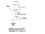
- FIG. 3A shows a case where the target medium is photographed with the LED of the smartphone (authenticity determination device 50) turned off. Because the LED is off, only ambient light is irradiated onto the target medium as reference light. However, because there is no hologram in the determination area, diffraction is not reproduced and the reflected light returns to the camera.
- Figure 3B shows the case where a counterfeit target medium is photographed with the smartphone's LED turned on. Because the LED is on, the target medium is irradiated with the LED light as reference light in addition to the ambient light. In this case, a bright spot caused by the LED light is detected in the determination area, and the specularly reflected light of the LED light is returned to the camera. Since no hologram is present in the determination area, the special diffracted light pattern (also called the "unique bright spot pattern" or "bright spot pattern”) described below is not seen.
- the special diffracted light pattern refers to a strong localized brightness change (diffracted light of the second hologram) that is detected around the zeroth-order diffracted light when the target medium is genuine, and is different from the "normal diffracted light pattern" (diffracted light of the first hologram) described below.
- FIG. 4 shows an example of shooting when the target medium is real and the LED is off. Because the LED is off, only ambient light is irradiated onto the target medium as reference light. When ambient light is irradiated onto the real target medium as reference light, it reproduces a normal diffracted light pattern (also called a "diffracted light pattern"; in the example shown, a crown pattern).
- a normal diffracted light pattern also called a "diffracted light pattern"; in the example shown, a crown pattern.
- the determination area is an area surrounding the area where normal diffracted light is reproduced, and is an area made up of a greater number of pixels than the area where normal diffracted light is reproduced. The extent to which the area has a greater number of pixels can be set in advance.
- FIG. 5 shows an example of shooting when the target medium is real and the LED is on. Since the LED is on, the target medium is irradiated with the LED light as reference light in addition to the ambient light.
- the real target medium is irradiated with LED light (light from a light source that can be considered as a point light source) as reference light, it reproduces a special diffracted light pattern (unique bright spot pattern) around the zeroth order diffracted light.
- a second hologram is recorded so that the special diffracted light pattern (unique bright spot pattern) is reproduced by the LED light.
- the special diffracted light pattern is the diffracted light of the second hologram.
- the determination area is an area surrounding the area where the special diffracted light pattern is reproduced, and is an area composed of a larger number of pixels than the area where the special diffracted light pattern is reproduced. The extent to which the area is made up of a larger number of pixels can be set in advance.
- the interference fringes caused by the interference of the reference light are recorded in advance, and a bright spot pattern is reproduced when the LED is on (first shooting condition), and a diffracted light pattern is reproduced when the LED is off (second shooting condition).
- first shooting condition has more reference light than the second shooting condition.
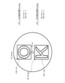
- a special diffracted light pattern is reproduced in the judgment area, with the zeroth-order diffracted light at the center, a bright spot pattern like the letter "O” on the upper side, and a bright spot pattern like the letter "K” on the lower side.
- the example of the hologram is just one example, and is not limited to the letters "O" and "K”.
- the zeroth-order diffracted light is total reflection light when all of the RGB color components are irradiated with a luminous intensity equal to or greater than the upper detection limit of the camera sensor (saturated or near-saturated state), and is a strong white bright spot.
- Luminous intensity represents the strength of light in any direction, and is given as the luminous flux per unit solid angle in a certain direction.
- the zeroth-order diffracted light is, for example, a circular or rectangular shape, and is an area where continuous bright spots are gathered. Note that the zeroth-order diffracted light in this invention refers to the central area of light obtained within the range captured by the image capturing unit 54 of the authenticity determination device 50, among the directions of the light reflected when light is incident on the target medium.
- the brightness of the special diffracted light pattern (unique bright spot pattern) is lower than that of the zeroth order diffracted light, but stronger than that of a normal diffracted light pattern.
- the special diffracted light pattern has non-uniform RGB color components, and does not result in white bright spots like the zeroth order diffracted light.
- Figure 6 shows the difference between a normal diffracted light pattern and a special diffracted light pattern.
- Figures 6A and 6B show images captured with the LED turned off.
- a normal diffracted light pattern in the example shown
- Figure 6B even if the smartphone is moved in the direction of the arrow relative to the judgment area, the position of the normal diffracted light pattern reproduced in the judgment area does not change.
- Figures 6C and 6D show images taken with the LED turned on.
- a special diffracted light pattern in the example shown, the letters "O" and "K” around the zeroth-order diffracted light
- Figure 6D when the smartphone is moved in the direction of the arrow relative to the judgment area, the position of the special diffracted light pattern in the judgment area moves along with the zeroth-order diffracted light, following the positions of the camera and LED light source. This is because the point of incidence of the LED light entering the judgment area moves.
- FIG. 7 is a diagram showing an example of medium-specific information 64.
- Medium-specific information 64 is information that associates a normal diffracted light pattern, a predetermined bright spot pattern (also called a "correct bright spot pattern"), a similarity threshold for the bright spot pattern, and a relative position threshold for the bright spot pattern for each type of target medium.
- a special diffracted light pattern is shown in FIG. 7. This is to illustrate the relative position of the predetermined bright spot pattern (correct bright spot pattern) contained in the special diffracted light pattern with respect to the zeroth-order diffracted light. In other words, the special diffracted light pattern does not need to be included in medium-specific information 64.
- a genuine target medium with a medium type of 001 has recorded thereon a first hologram that reproduces a normal diffracted light pattern with a pattern like a crown, and a second hologram that reproduces a pattern A with a pattern like the letter "O" above the zeroth-order diffracted light and a pattern B with a pattern like the letter "O” below the zeroth-order diffracted light.
- the similarity threshold for pattern A is Sa
- the similarity threshold for pattern B is Sb.
- the relative position (x, y coordinate) threshold for pattern A is (Tax, Tay)
- the relative position (x, y coordinate) threshold for pattern B is (Tbx, Tby).
- a genuine target medium with a medium type of 002 has recorded thereon a first hologram that reproduces a normal diffracted light pattern of a design like a trophy, and a second hologram that reproduces a pattern C of a design like the letter "E" on the left side of the zeroth order diffracted light and a pattern D of a design like the letter "F” on the right side of the zeroth order diffracted light.
- the similarity threshold of pattern C is Sc
- the similarity threshold of pattern D is Sd.
- the relative position (x, y coordinate) threshold of pattern C is (Tcx, Tcy)
- the relative position (x, y coordinate) threshold of pattern D is (Tdx, Tdy).
- the control unit 51 acquires a second image of the target medium captured with the LED off (second capture condition), identifies a diffracted light pattern based on the acquired second image, and determines the type of target medium based on the identified diffracted light pattern.
- the similarity between the identified diffracted light pattern and each of the multiple normal diffracted light patterns included in the medium-specific information 64 is calculated, and the medium type corresponding to the normal diffracted light pattern with the calculated similarity equal to or greater than a predetermined value can be determined as the medium type of the target medium.
- the type of the target medium will be described as medium type 001 in FIG. 7.
- the control unit 51 can select a predetermined bright spot pattern of the target medium that corresponds to a predetermined diffracted light pattern similar to the identified diffracted light pattern, a predetermined similarity threshold, and a predetermined relative position threshold.
- the similarity between the identified diffracted light pattern and the predetermined diffracted light pattern can be determined, for example, by using a pattern matching process, calculating the mean square error of the luminance value for each corresponding pixel between the identified diffracted light pattern and the predetermined diffracted light pattern, adding the mean square errors calculated for each pixel, and taking the reciprocal of the added value as the similarity.
- control unit 51 selects pattern A and pattern B as the predetermined bright spot pattern (correct bright spot pattern), and selects the similarity threshold Sa and relative position threshold (Tax, Tay) of pattern A, and the similarity threshold Sb and relative position threshold (Tbx, Tby) of pattern B, which can be used to determine the authenticity of the target medium.
- FIG. 8 is a diagram showing an example of a method for detecting a bright spot pattern.
- the control unit 51 acquires a captured image (first image) of the target medium with the LED turned on (first capture condition), and identifies a bright spot region based on the acquired captured image.
- a bright spot region is a region in which zero-order diffracted light appears, and can be a collection (collection) of pixels that have strong white bright spots that are saturated or close to being saturated.
- the control unit 51 can perform a filter process on the acquired captured image to identify areas with a predetermined luminance or higher as bright spot areas.
- the filter process is performed on each pixel of the captured image, and is, for example, a process of extracting only pixels with a required pixel value. In this specification, pixels with saturated bright spots are extracted.
- a bright spot area can be identified by performing a process of leaving only strong white bright spots that are saturated or close to being saturated among the bright spots in the captured image.
- the control unit 51 performs a zeroth-order diffracted light detection process on the bright spot area to detect the zeroth-order diffracted light coordinates.
- the zeroth-order diffracted light detection process includes, for example, (1) a process of determining whether all of the RGB color components are strong white bright spots that are saturated or close to being saturated, (2) a process of calculating the shape and area of the zeroth-order diffracted light based on the number of pixels in an area where pixels of saturated bright spots or bright spots close to being saturated are consecutive, and (3) a process of calculating the coordinates of the center point.
- the control unit 51 performs a process of detecting the bright spot pattern. Specifically, the control unit 51 detects the bright spot pattern in the peripheral area of the zeroth-order diffracted light.
- the peripheral area can be the range imaged by the image capturing unit 54. In this specification, the peripheral area can be the judgment area.
- the brightness of the bright spot pattern is lower than the zeroth-order diffracted light, but stronger than a normal diffracted light pattern, so it is sufficient to detect bright spots within a predetermined brightness value range. In the example of Figure 8, pattern A of the letter "O" and pattern B of the letter "K" are detected.
- Figure 9 shows an example of a method for calculating the relative positions of detected bright spot patterns.
- the detected bright spot patterns are pattern A (letter "O") and pattern B (letter "K”).
- a rectangle enclosing pattern A and a rectangle enclosing pattern B are identified.
- One of the four corners of each rectangle (the upper left corner in the example shown) is set as the detection position of the pattern.
- the coordinates of detection position A1 of pattern A are set as (ax, ay), and the coordinates of detection position B1 of pattern B are set as (bx, by).
- the coordinates of the center position O of the zeroth-order diffracted light are set as (u, v).
- Iax can be calculated as Iax-u
- Iay can be calculated as Iay-v
- Ibx can be calculated as Ibx-u
- Iby can be calculated as Iby-v.
- the detection position of the bright spot pattern is the upper left corner of the rectangle, but this is not limited to this and may be any other corner of the four corners or the center position of the rectangle.
- FIG. 10 is a diagram showing an example of a method for determining the authenticity of a target medium.
- the control unit 51 identifies the feature amount of the peripheral area of the zero-order diffracted light (bright spot area) and determines the authenticity of the target medium based on the identified feature amount.
- the authenticity determination result of the target medium can be obtained by simply performing a simple operation, and no special skills or expertise are required.
- the control unit 51 may also specify the similarity between the bright spot pattern in the peripheral region of the zero-order diffracted light and a predetermined bright spot pattern as the feature amount, and determine the authenticity of the target medium based on the specified similarity and a similarity threshold.
- the calculation of the similarity can use, for example, a template matching method as described below. That is, the mean square error of the luminance value for each corresponding pixel between the bright spot pattern and the predetermined bright spot pattern is calculated, the mean square error calculated for each pixel is added, and the reciprocal of the sum is taken as the similarity.
- the similarity is a value equivalent to the reciprocal of the value calculated based on the mean square error, so the greater the similarity, the more similar the bright spot pattern and the predetermined bright spot pattern are. Note that the calculation of the similarity is not limited to the template matching method.
- the control unit 51 may also specify, as the feature, the relative position between a predetermined position of the bright spot pattern in the peripheral area of the zeroth-order diffracted light and the position of the zeroth-order diffracted light (bright spot area), and determine the authenticity of the target medium based on the specified relative position and a relative position threshold.
- the predetermined position of the bright spot pattern may be the detection position of the bright spot pattern
- the position of the zeroth-order diffracted light may be the central position of the zeroth-order diffracted light (see FIG. 9).
- the detected bright spot patterns are pattern A and pattern B.
- the control unit 51 first performs an authenticity determination of the target medium based on pattern A.
- the authenticity determination conditions can be (1) that the similarity between pattern A and the correct bright spot pattern selected from the medium specific information 64 is equal to or greater than a similarity threshold value Sa, and (2) that the difference ( ⁇ x, ⁇ y) between the relative position (Iax, Iay) of pattern A and the relative position threshold value (Tax, Tay) is within a predetermined range (for example, within ⁇ 5% of the size of the captured image). If the authenticity determination conditions are met, the target medium is determined to be genuine. If the authenticity determination conditions are not met, the target medium can be determined to be a counterfeit.
- the control unit 51 performs an authenticity determination of the target medium based on pattern B.
- the authenticity determination conditions can be (1) the similarity between pattern B and the correct bright spot pattern selected from the medium-specific information 64 is equal to or greater than the similarity threshold Sb, and (2) the difference ( ⁇ x, ⁇ y) between the relative position (Ibx, Iby) of pattern B and the relative position threshold (Tbx, Tby) is within a predetermined range (for example, within ⁇ 5% of the size of the captured image, but is not limited to ⁇ 5%). If the authenticity determination conditions are met, the target medium is determined to be genuine. If the authenticity determination conditions are not met, the target medium can be determined to be a counterfeit.
- control unit 51 can determine the authenticity of the target medium based on whether the identified similarity is equal to or greater than the similarity threshold, and whether the difference between the identified relative position and the relative position threshold is within a predetermined relative position range.
- control unit 51 can determine that the target medium is genuine based on at least one of the detected bright spot patterns (pattern A and pattern B), it can ultimately determine that the target medium is genuine.
- the authenticity of a target medium can be determined without special skills or expertise, simply by photographing the target medium with the LED light source (a light source that can be considered as a point light source) of an authenticity determination device such as a smartphone turned on.
- the type of target medium can be determined simply by photographing the target medium with the LED light source turned off, the authenticity of various types of target media can be determined.
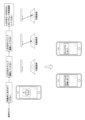
- FIG. 11 is a diagram showing an example of operations for determining the authenticity of a target medium. Below, an example is described in which a voice guide is used to guide the user, but the guidance may also be a method of displaying text, etc., or a combination of text and voice. As shown in FIG. 11A, the user only needs to carry out the following four steps of operations.
- step 1 the position of the smartphone is adjusted so that the judgment area of the target medium falls within a specified frame in the field of view of the camera.
- a voice guide such as "Please align it within the frame lines" may be output.
- the control unit 51 may output guidance so that the judgment area of the target medium falls within the shooting range. This allows the user to properly shoot the target medium.
- guidance may be given to ensure that the target medium (particularly the judgment area) is not affected by the zero-order reflected light. For example, the user may be advised to be careful not to let the judgment area and the zero-order reflected light area overlap.
- step 2 the user turns off the LED and takes a picture of the target medium.
- audio guidance such as "Please turn off the LED before taking a picture” may be output.
- step 3 the user turns on the LED and takes a picture of the target medium.
- a voice guide such as "Turn on the LED and take a picture” may be output. Note that there are no particular restrictions on the position or angle of the smartphone as long as the target medium (particularly the judgment area) is within the field of view for taking a picture.
- step 4 audio guidance is output to the user as necessary. For example, audio such as “Leave the LED on and shift it slightly to the right and take the picture again” is output.
- the control unit 51 can output guidance so that the position of the zero-order diffracted light (bright spot area) present at the center of the special diffracted light pattern is in the center of the shooting range. This allows the bright spot pattern included in the special diffracted light pattern to be included in the judgment area without any part being missing, improving the judgment accuracy of authenticity judgment.
- the smartphone's display screen will show the result of the authenticity determination of the target medium (for example, as shown in FIG. 11B, "Hologram recognized” is displayed, indicating that the target medium is genuine, or as shown in FIG. 11C, "Timeout occurred” is displayed, indicating that the target medium is a counterfeit).
- the authenticity determination result may also be output as audio.
- FIG 12 is a diagram showing an example of the processing procedure for authenticity determination by authenticity determination device 50.
- the control unit 51 acquires an image (second image) taken with the LED off (S11), identifies a diffracted light pattern (normal diffracted light pattern) based on the acquired image, and determines the type of the target medium based on the identified diffracted light pattern (S13). Specifically, it calculates the similarity between the identified diffracted light pattern and each of multiple normal diffracted light patterns included in medium-specific information 64, and the medium type corresponding to the normal diffracted light pattern with a calculated similarity equal to or greater than a predetermined value can be determined as the type of the target medium.
- the control unit 51 selects the correct bright spot pattern, similarity threshold, and relative position threshold corresponding to the determined type from the medium-specific information 64 (S14).
- the control unit 51 acquires an image (first image) captured with the LED on (S15). Note that the process of step S15 may be performed after the process of step S11, or may be performed before the process of step S11.
- the control unit 51 performs a filter process on the acquired image (first image) to detect the position of the zeroth-order diffracted light (S16).
- the control unit 51 identifies a bright spot pattern in the peripheral area of the zeroth-order diffracted light (S17) and calculates the relative position of the identified bright spot pattern (S18).
- the control unit 51 calculates the similarity between the identified bright spot pattern and the correct bright spot pattern selected in step S14 (S19).
- the control unit 51 calculates the difference between the calculated relative position of the bright spot pattern and the relative position threshold (S20), judges the authenticity of the target medium based on the calculated similarity and difference (S21), outputs the judgment result (S22), and ends the process.
- the position of the zeroth-order diffracted light can be identified, and the position of the bright spot pattern can also be identified based on the position of the zeroth-order diffracted light. This reduces the problem of not being able to accurately identify the shape and position of the bright spot pattern due to a shift in the relative position between the target medium and the light source and camera, for example, and improves the accuracy of authenticity determination.
- the computer program causes a computer to execute a process of acquiring a first image of a target medium captured under first capturing conditions, identifying a bright spot area based on the acquired first image, identifying features of an area surrounding the bright spot area, and determining the authenticity of the target medium based on the identified features.
- Appendix 2 The computer program in Appendix 1 causes a computer to execute a process that identifies, as the feature, the similarity between the bright spot pattern in the surrounding area and a specified bright spot pattern, and determines the authenticity of the target medium based on the identified similarity and a similarity threshold.
- appendix 3 In appendix 1 or appendix 2, the computer program causes the computer to execute a process of identifying, as the feature, a relative position between a predetermined position of the bright spot pattern in the peripheral area and the position of the bright spot area, and determining the authenticity of the target medium based on the identified relative position and a relative position threshold.
- Appendix 4 The computer program in Appendix 3 causes the computer to execute a process to determine the authenticity of the target medium depending on whether the identified similarity is equal to or greater than the similarity threshold, and whether the difference between the identified relative position and the relative position threshold is within a predetermined relative position range.
- appendix 5 The computer program in any one of appendices 1 to 4 causes the computer to execute a process of filtering the acquired first image and identifying an area having a predetermined luminous intensity or higher as the bright spot area.
- Appendix 6 The computer program in any one of appendices 1 to 5 causes a computer to execute a process of acquiring a second image of the target medium captured under second capturing conditions, identifying a diffracted light pattern based on the acquired second image, and determining the type of the target medium based on the identified diffracted light pattern.
- Appendix 7 The computer program in Appendix 6 causes the computer to execute a process that calculates the similarity between the identified diffracted light pattern and each of a plurality of predetermined diffracted light patterns for each type of target medium, and identifies the type of target medium that corresponds to the predetermined diffracted light pattern for which the calculated similarity is equal to or greater than a predetermined value.
- Appendix 8 The computer program in any one of appendices 1 to 7 causes a computer to execute a process of storing a predetermined diffracted light pattern, a predetermined bright spot pattern, and a predetermined relative position threshold value in association with each type of target medium, and selecting a predetermined bright spot pattern of the target medium and a predetermined relative position threshold value that correspond to a predetermined diffracted light pattern similar to the identified diffracted light pattern.
- the computer program causes the computer to execute a process in any one of appendices 1 to 9, which outputs guidance so that the position of the bright spot area is in the center of the shooting range.
- the computer program causes the computer to execute a process in which a predetermined zeroth-order diffracted light detection process is performed on the identified bright spot region in any one of appendices 1 to 10 to detect the zeroth-order diffracted light coordinates.
- the computer program causes the computer to execute a process in which, when there are multiple identified bright spot areas in any one of appendices 1 to 11, if the target medium can be determined to be genuine based on at least one of the multiple bright spot areas, the target medium is finally determined to be genuine.
- the computer program causes the computer to execute a process in any one of appendices 1 to 12, which outputs guidance so that the determination area of the target medium is within the shooting range.
- Appendix 14 The computer program causes a computer to execute a process in any one of appendices 1 to 13, which outputs guidance before starting shooting so that there is no effect of zero-order reflected light on the target medium.
- the authenticity determination device includes a control unit, which acquires a first image of the target medium captured under first shooting conditions, identifies a bright spot area based on the acquired first image, identifies features of the surrounding area of the bright spot area, and determines the authenticity of the target medium based on the identified features.
- control unit 16 In the authenticity determination device of appendix 15, the control unit identifies the similarity between the bright spot pattern in the surrounding area and a specified bright spot pattern as the feature amount, and determines the authenticity of the target medium based on the identified similarity and a similarity threshold value.
- control unit In the authenticity determination device of appendix 15 or appendix 16, the control unit identifies, as the feature, a relative position between a predetermined position of a bright spot pattern in the peripheral area and the position of the bright spot area, and determines the authenticity of the target medium based on the identified relative position and a relative position threshold.
- control unit determines the authenticity of the target medium depending on whether the identified similarity is equal to or greater than the similarity threshold, and whether the difference between the identified relative position and the relative position threshold is within a predetermined relative position range.
- control unit performs a filter process on the acquired first image and identifies an area having a predetermined luminous intensity or higher as the bright spot area.
- control unit acquires a second image of the target medium captured under second imaging conditions, identifies a diffracted light pattern based on the acquired second image, and determines the type of the target medium based on the identified diffracted light pattern.
- the authenticity determination device stores a predetermined diffracted light pattern, a predetermined bright spot pattern, and a predetermined relative position threshold value for each type of target medium, and the control unit selects the predetermined bright spot pattern of the target medium and the predetermined relative position threshold value that correspond to the predetermined diffracted light pattern similar to the identified diffracted light pattern.
- the genuine target medium has pre-recorded interference fringes caused by the interference of reference light, a bright spot pattern is reproduced under a first shooting condition, and a diffracted light pattern is reproduced under a second shooting condition, and the first shooting condition has more reference light than the second shooting condition.
- control unit In the authenticity determination device according to any one of appendices 15 to 22, the control unit outputs guidance so that the position of the bright spot area is in the center of the shooting range.
- the authenticity determination method involves obtaining a first image of the target medium under first shooting conditions, identifying a bright spot area based on the obtained first image, identifying features of the area surrounding the bright spot area, and determining the authenticity of the target medium based on the identified features.
- Control unit 52 Communication unit 53 Memory 54 Image capture unit 55 Light emission control unit 56 Medium type determination unit 57 Image processing unit 58 Determination unit 59 Display unit 60 Operation unit 61 Audio output unit 62 Storage unit 63 Computer program 64 Medium specific information
Landscapes
- Engineering & Computer Science (AREA)
- Computer Security & Cryptography (AREA)
- Physics & Mathematics (AREA)
- General Physics & Mathematics (AREA)
- Inspection Of Paper Currency And Valuable Securities (AREA)
Priority Applications (1)
| Application Number | Priority Date | Filing Date | Title |
|---|---|---|---|
| JP2025501237A JPWO2024172161A1 (https=) | 2023-02-17 | 2024-02-16 |
Applications Claiming Priority (2)
| Application Number | Priority Date | Filing Date | Title |
|---|---|---|---|
| JP2023023623 | 2023-02-17 | ||
| JP2023-023623 | 2023-02-17 |
Publications (1)
| Publication Number | Publication Date |
|---|---|
| WO2024172161A1 true WO2024172161A1 (ja) | 2024-08-22 |
Family
ID=92420061
Family Applications (1)
| Application Number | Title | Priority Date | Filing Date |
|---|---|---|---|
| PCT/JP2024/005592 Ceased WO2024172161A1 (ja) | 2023-02-17 | 2024-02-16 | 真贋判定装置、コンピュータプログラム及び真贋判定方法 |
Country Status (2)
| Country | Link |
|---|---|
| JP (1) | JPWO2024172161A1 (https=) |
| WO (1) | WO2024172161A1 (https=) |
Cited By (1)
| Publication number | Priority date | Publication date | Assignee | Title |
|---|---|---|---|---|
| JP7613644B1 (ja) * | 2023-03-13 | 2025-01-15 | 大日本印刷株式会社 | プログラム、情報処理方法及び情報処理装置 |
Citations (6)
| Publication number | Priority date | Publication date | Assignee | Title |
|---|---|---|---|---|
| US20150098642A1 (en) * | 2013-10-04 | 2015-04-09 | Giesecke & Devrient America, Inc. | Systems, methods, and computer-readable media for sheet material processing and verification |
| WO2018021048A1 (ja) * | 2016-07-27 | 2018-02-01 | 凸版印刷株式会社 | 色校正装置、色校正システム、色校正用ホログラム、色校正方法及びプログラム |
| JP2019082604A (ja) * | 2017-10-31 | 2019-05-30 | 凸版印刷株式会社 | 表示デバイス |
| JP2019144987A (ja) * | 2018-02-23 | 2019-08-29 | 凸版印刷株式会社 | 光学素子媒体の判別方法 |
| JP2020094183A (ja) * | 2018-10-22 | 2020-06-18 | 三菱瓦斯化学株式会社 | 熱可塑性樹脂の平板状成形体、多層体、真贋判定方法、真贋判定システムおよびプログラム |
| JP2021167964A (ja) * | 2016-10-07 | 2021-10-21 | 株式会社アーティエンス・ラボ | 情報認識方法 |
Family Cites Families (2)
| Publication number | Priority date | Publication date | Assignee | Title |
|---|---|---|---|---|
| CH693693A5 (de) * | 1997-06-06 | 2003-12-15 | Ovd Kinegram Ag | Vorrichtung zum Erkennen beugungsoptischer Markierungen. |
| US10762314B2 (en) * | 2017-05-10 | 2020-09-01 | Datalogic Ip Tech S.R.L. | Anti-counterfeiting barcode reader and associated methods |
-
2024
- 2024-02-16 WO PCT/JP2024/005592 patent/WO2024172161A1/ja not_active Ceased
- 2024-02-16 JP JP2025501237A patent/JPWO2024172161A1/ja active Pending
Patent Citations (6)
| Publication number | Priority date | Publication date | Assignee | Title |
|---|---|---|---|---|
| US20150098642A1 (en) * | 2013-10-04 | 2015-04-09 | Giesecke & Devrient America, Inc. | Systems, methods, and computer-readable media for sheet material processing and verification |
| WO2018021048A1 (ja) * | 2016-07-27 | 2018-02-01 | 凸版印刷株式会社 | 色校正装置、色校正システム、色校正用ホログラム、色校正方法及びプログラム |
| JP2021167964A (ja) * | 2016-10-07 | 2021-10-21 | 株式会社アーティエンス・ラボ | 情報認識方法 |
| JP2019082604A (ja) * | 2017-10-31 | 2019-05-30 | 凸版印刷株式会社 | 表示デバイス |
| JP2019144987A (ja) * | 2018-02-23 | 2019-08-29 | 凸版印刷株式会社 | 光学素子媒体の判別方法 |
| JP2020094183A (ja) * | 2018-10-22 | 2020-06-18 | 三菱瓦斯化学株式会社 | 熱可塑性樹脂の平板状成形体、多層体、真贋判定方法、真贋判定システムおよびプログラム |
Cited By (1)
| Publication number | Priority date | Publication date | Assignee | Title |
|---|---|---|---|---|
| JP7613644B1 (ja) * | 2023-03-13 | 2025-01-15 | 大日本印刷株式会社 | プログラム、情報処理方法及び情報処理装置 |
Also Published As
| Publication number | Publication date |
|---|---|
| JPWO2024172161A1 (https=) | 2024-08-22 |
Similar Documents
| Publication | Publication Date | Title |
|---|---|---|
| JP7541028B2 (ja) | 制御照明を用いた表面外観の判定による文書認証方法 | |
| TWI435277B (zh) | 利用與快速遮罩正規化交互相關匹配之範本的文件驗證 | |
| KR102081314B1 (ko) | 식별 장치, 식별 방법, 및 식별 프로그램을 포함하는 컴퓨터 판독 가능 기록 매체 | |
| EA025922B1 (ru) | Способ автоматической аутентификации защищенного документа | |
| CN110263775B (zh) | 图像识别方法、装置、设备和认证方法、装置、设备 | |
| CN110490200B (zh) | 一种证件扫描方法、装置及设备 | |
| CN115439851A (zh) | 一种验证待识别证件图像的方法、系统及设备 | |
| CN115280384B (zh) | 用于认证安全证件的方法 | |
| Hartl et al. | Efficient verification of holograms using mobile augmented reality | |
| JPWO2017090652A1 (ja) | 識別装置、識別方法、識別プログラム、及び識別プログラムを含むコンピュータ可読媒体 | |
| WO2024172161A1 (ja) | 真贋判定装置、コンピュータプログラム及び真贋判定方法 | |
| JP5244283B2 (ja) | 画像の形状内容に関する半径方向および角配向または回転方向解析と照合のための装置および方法 | |
| Koliaskina et al. | Midv-holo: A dataset for id document hologram detection in a video stream | |
| JP7485236B2 (ja) | コンピュータプログラム、真贋判定装置及び真贋判定方法 | |
| US7126729B2 (en) | Double hologram | |
| FI20225103A1 (en) | Camera, system for detecting an optical identity and identification method | |
| JP2025093117A (ja) | 真贋判定システム、真贋判定装置、コンピュータプログラム及び真贋判定方法 | |
| KR101812206B1 (ko) | 위폐 감별 및 추적 시스템 및 이의 실행 방법 | |
| JP2025072139A (ja) | 真贋判定装置、コンピュータプログラム及び真贋判定方法 | |
| JP2025105321A (ja) | 真贋判定装置、コンピュータプログラム及び真贋判定方法 | |
| JP7593095B2 (ja) | コンピュータプログラム、真贋判定方法及び真贋判定装置 | |
| JP7069627B2 (ja) | 情報記録媒体の読み取り方法および真贋判定方法 | |
| JP7613644B1 (ja) | プログラム、情報処理方法及び情報処理装置 | |
| CN120147757B (zh) | 一种印刷品图像真伪判定方法及系统 | |
| CN119091534B (zh) | 非接触式快速点钞方法、系统、设备、储存介质及程序 |
Legal Events
| Date | Code | Title | Description |
|---|---|---|---|
| 121 | Ep: the epo has been informed by wipo that ep was designated in this application |
Ref document number: 24757000 Country of ref document: EP Kind code of ref document: A1 |
|
| WWE | Wipo information: entry into national phase |
Ref document number: 2025501237 Country of ref document: JP |
|
| NENP | Non-entry into the national phase |
Ref country code: DE |
|
| 122 | Ep: pct application non-entry in european phase |
Ref document number: 24757000 Country of ref document: EP Kind code of ref document: A1 |