WO2024172012A1 - シール付玉軸受及び軸受装置 - Google Patents
シール付玉軸受及び軸受装置 Download PDFInfo
- Publication number
- WO2024172012A1 WO2024172012A1 PCT/JP2024/004759 JP2024004759W WO2024172012A1 WO 2024172012 A1 WO2024172012 A1 WO 2024172012A1 JP 2024004759 W JP2024004759 W JP 2024004759W WO 2024172012 A1 WO2024172012 A1 WO 2024172012A1
- Authority
- WO
- WIPO (PCT)
- Prior art keywords
- bearing
- seal
- diameter
- cage
- Prior art date
- Legal status (The legal status is an assumption and is not a legal conclusion. Google has not performed a legal analysis and makes no representation as to the accuracy of the status listed.)
- Ceased
Links
Images






Classifications
-
- F—MECHANICAL ENGINEERING; LIGHTING; HEATING; WEAPONS; BLASTING
- F16—ENGINEERING ELEMENTS AND UNITS; GENERAL MEASURES FOR PRODUCING AND MAINTAINING EFFECTIVE FUNCTIONING OF MACHINES OR INSTALLATIONS; THERMAL INSULATION IN GENERAL
- F16C—SHAFTS; FLEXIBLE SHAFTS; ELEMENTS OR CRANKSHAFT MECHANISMS; ROTARY BODIES OTHER THAN GEARING ELEMENTS; BEARINGS
- F16C19/00—Bearings with rolling contact, for exclusively rotary movement
- F16C19/02—Bearings with rolling contact, for exclusively rotary movement with bearing balls essentially of the same size in one or more circular rows
- F16C19/04—Bearings with rolling contact, for exclusively rotary movement with bearing balls essentially of the same size in one or more circular rows for radial load mainly
- F16C19/06—Bearings with rolling contact, for exclusively rotary movement with bearing balls essentially of the same size in one or more circular rows for radial load mainly with a single row or balls
-
- F—MECHANICAL ENGINEERING; LIGHTING; HEATING; WEAPONS; BLASTING
- F16—ENGINEERING ELEMENTS AND UNITS; GENERAL MEASURES FOR PRODUCING AND MAINTAINING EFFECTIVE FUNCTIONING OF MACHINES OR INSTALLATIONS; THERMAL INSULATION IN GENERAL
- F16C—SHAFTS; FLEXIBLE SHAFTS; ELEMENTS OR CRANKSHAFT MECHANISMS; ROTARY BODIES OTHER THAN GEARING ELEMENTS; BEARINGS
- F16C33/00—Parts of bearings; Special methods for making bearings or parts thereof
- F16C33/30—Parts of ball or roller bearings
- F16C33/38—Ball cages
-
- F—MECHANICAL ENGINEERING; LIGHTING; HEATING; WEAPONS; BLASTING
- F16—ENGINEERING ELEMENTS AND UNITS; GENERAL MEASURES FOR PRODUCING AND MAINTAINING EFFECTIVE FUNCTIONING OF MACHINES OR INSTALLATIONS; THERMAL INSULATION IN GENERAL
- F16C—SHAFTS; FLEXIBLE SHAFTS; ELEMENTS OR CRANKSHAFT MECHANISMS; ROTARY BODIES OTHER THAN GEARING ELEMENTS; BEARINGS
- F16C33/00—Parts of bearings; Special methods for making bearings or parts thereof
- F16C33/72—Sealings
- F16C33/76—Sealings of ball or roller bearings
- F16C33/78—Sealings of ball or roller bearings with a diaphragm, disc, or ring, with or without resilient members
-
- F—MECHANICAL ENGINEERING; LIGHTING; HEATING; WEAPONS; BLASTING
- F16—ENGINEERING ELEMENTS AND UNITS; GENERAL MEASURES FOR PRODUCING AND MAINTAINING EFFECTIVE FUNCTIONING OF MACHINES OR INSTALLATIONS; THERMAL INSULATION IN GENERAL
- F16J—PISTONS; CYLINDERS; SEALINGS
- F16J15/00—Sealings
- F16J15/16—Sealings between relatively-moving surfaces
- F16J15/32—Sealings between relatively-moving surfaces with elastic sealings, e.g. O-rings
- F16J15/3204—Sealings between relatively-moving surfaces with elastic sealings, e.g. O-rings with at least one lip
-
- F—MECHANICAL ENGINEERING; LIGHTING; HEATING; WEAPONS; BLASTING
- F16—ENGINEERING ELEMENTS AND UNITS; GENERAL MEASURES FOR PRODUCING AND MAINTAINING EFFECTIVE FUNCTIONING OF MACHINES OR INSTALLATIONS; THERMAL INSULATION IN GENERAL
- F16J—PISTONS; CYLINDERS; SEALINGS
- F16J15/00—Sealings
- F16J15/16—Sealings between relatively-moving surfaces
- F16J15/32—Sealings between relatively-moving surfaces with elastic sealings, e.g. O-rings
- F16J15/3244—Sealings between relatively-moving surfaces with elastic sealings, e.g. O-rings with hydrodynamic pumping action
Definitions
- This invention relates to sealed ball bearings and bearing devices.
- bearings are used on the motor shafts of transmissions (speed reducers) equipped with drive motors in various vehicles such as automobiles and construction machinery, as well as various industrial machines.
- the bearings used in these devices are generally used under high-speed conditions compared to bearings used to support shafts in general equipment.
- the lubricating oil used in these devices contains foreign matter such as gear wear powder. For this reason, by providing a seal member on the end of the bearing, it is possible to prevent foreign matter from entering the inside of the bearing, thereby suppressing the reduction in bearing life, and by suppressing the amount of lubricating oil that enters, it is possible to reduce the agitation resistance.
- Patent Document 1 a protrusion is provided on the seal lip of the seal member, creating an oil passage that connects the inside and outside of the bearing, creating a fluid lubrication state between the seal lip and the seal sliding surface. This suppresses the reduction in bearing life caused by gear wear debris, etc., while achieving fluid lubrication of the seal portion and reducing seal torque.
- Patent Document 2 also discloses a technology in which a crown-type cage has an annular base and columns protruding from the base, the radial thickness of the crown-type cage gradually decreases from the base to the tips of the columns, and the radial gap between the outer peripheral surface of the base and the inner peripheral surface of the shoulder of the outer ring is larger than the radial gap between the inner peripheral surface of the base and the outer peripheral surface of the shoulder of the inner ring.
- Patent Document 2 even if the lubricant is scattered by centrifugal force during high-speed rotation, the lubricant is stored between the outer peripheral surface of the base and the inner peripheral surface of the shoulder of the outer ring, preventing the lubricant from flowing into the raceway surface of the outer ring. This reduces the stirring resistance, enabling lower torque and reduced heat generation, and is said to prevent deformation of the cage due to centrifugal force during high-speed rotation.
- Patent Document 1 it is possible to suppress the decrease in bearing life.
- bearings used under high-speed conditions such as supporting the motor shaft of a drive motor
- the raceway rings may heat up due to interference with the cage and the cage may be damaged under harsher operating conditions than expected.
- the objective of this invention is to prevent foreign matter from entering the internal space of the bearing while suppressing deformation of the cage under high-speed conditions.
- the present invention provides a bearing having an inner ring, an outer ring, balls arranged between the inner ring and the outer ring, a cage having pockets for holding the balls in the circumferential direction, and a seal member for closing an opening at an axial end of an internal space formed between the inner ring and the outer ring, and D: Bearing outer diameter (mm) d: bearing inner diameter (mm) n: rotation speed (rpm) and a sealed ball bearing is used in an environment where the dmn value defined by the formula (I) is 700,000 or more, the cage is a crown cage containing an engineering plastic, and a dimensional relationship between a diameter ⁇ x of the balls, a radius Ry of an inner circumferential surface of the pocket in a cross section that passes through the center of the pocket and includes the axis of the bearing, and a diameter ⁇ z of the inner circumferential surface of the pocket in a cross section that is perpendicular to a radial line passing through the center of the pocket at
- a configuration (configuration 2) can be adopted in which the seal lip is made of a single or multiple materials selected from nitrile rubber, acrylic rubber, and fluororubber.
- a configuration (configuration 3) can be adopted in which the seal member is provided only at the opening on the one axial end side.
- a bearing device using any of these sealed ball bearings can be used to support the rotating shaft of a drive motor, reducer, or speed increaser for electric transport equipment.
- This invention employs a seal member that can maintain a fluid lubrication state between the seal lip and the seal sliding surface, thereby reducing the seal torque and controlling the amount of lubricant flowing into the bearing internal space. This reduces the agitation resistance of the lubricant in the bearing internal space, making it possible to use the bearing in a high-speed rotation range with a dmn value of 700,000 or more. At the same time, it also prevents the intrusion of foreign matter of a size that could affect the bearing life.
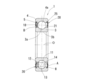
- FIG. 1 is a vertical cross-sectional view showing an embodiment of the present invention.
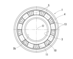
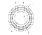
- FIG. 2 is a right side view of the state in which the seal member of FIG. 1 is removed.
- FIG. 2 is a left side view of the state where the seal member of FIG. 1 is removed.
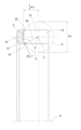
- Enlarged view of the main part of Figure 1 An enlarged view of the main part of the seal ship shown in FIG. VI-VI cross-sectional view of FIG.
- FIG. 6B is an enlarged view of a main part of FIG.
- Schematic diagram of cross section II of FIG. 9A Schematic diagram of a cross section taken along line II-II of FIG.
- FIG. 11 is a vertical cross-sectional view showing a modified example
- This embodiment is a rolling bearing 1 equipped with a seal member 20 at the opening at the axial end of the internal space of the bearing.
- the rolling bearing 1 comprises an inner ring 3, an outer ring 4, a number of rolling elements 5 arranged between the inner ring 3 and the outer ring 4, and a cage 10 having pockets 11 that hold the balls 5 in the circumferential direction. Because spheres (steel balls) are used as the rolling elements 5, they will be referred to as balls 5 below. Furthermore, this rolling bearing 1 will be referred to as a sealed ball bearing 1 or simply as a bearing 1 below.
- bearing axial direction the direction along the bearing central axis of the bearing 1
- axial direction the direction along the bearing central axis of the bearing 1
- radial direction the direction perpendicular to the axial direction
- radial circumferential direction the direction around the bearing central axis
- circumferential direction the circumferential direction around the bearing central axis
- the cage 10 is a crown-shaped cage molded from engineering plastic.
- the cage 10 has an annular base 12 and multiple pillars 13 that protrude axially from the base 12. Pairs of pillars 13, 13 are arranged in parallel along the circumferential direction and are spaced at regular intervals along the circumferential direction. A concave pocket 11 is formed between the pair of pillars 13.
- the outer diameter surface of the cage 10 is a curved surface (cylindrical surface) with no steps. The outer diameter surface and inner diameter surface of the cage 10 are connected at the pocket 11.
- the tip of the pillar portion 13 is a retaining claw 14.
- the retaining claws 14, 14 on both sides of the pocket 11 are curved in a direction approaching each other.
- adjacent pillar portions 13, 13 may be connected to each other between adjacent pockets 11 in the circumferential direction.
- the balls 5 held by the pockets 11 revolve between the raceway surface 3a of the inner ring 3 and the raceway surface 4a of the outer ring 4 while being held by the pockets 11.
- the inner ring 3 has a rotating shaft (not shown) fixed to its inner diameter portion 3b, and rotates in the circumferential direction together with the rotating shaft.
- the outer ring 4 is a member such as a housing or gear (also not shown), and is attached to a fixed member that bears the load from the rotating shaft.
- the bearing 1 supports the rotating shaft so that it can rotate freely relative to the fixed member.
- the rotating shaft referred to here may be, for example, the rotating shaft of a drive motor equipped in an electric transport device such as an electric vehicle, or the rotating shaft of a reducer or speed increaser equipped in such an electric transport device.
- the bearing center axis of the bearing 1 and the rotating center axis of the rotating shaft are set coaxially.
- an appropriate lubricant such as grease is sealed in the bearing internal space A.
- a lubricant lubricating oil
- the bearing 1 is basically used under oil lubrication, and the grease sealed in as initial lubrication is then replaced with lubricating oil supplied from outside the bearing.
- the lubricating oil that lubricates devices such as drive motors and transmissions contains gear wear powder, clutch wear powder, and other foreign matter depending on the device in which bearing 1 is installed. It is desirable for these foreign matter to be captured somewhere rather than floating in the lubricating oil. Furthermore, bearing 1 is lubricated with the same lubricating oil as these devices such as drive motors and transmissions. For this reason, a seal member 20 is attached to the opening at the axial end of bearing internal space A. In this embodiment, a seal member 20 is provided at each of both axial ends of bearing internal space A.
- the seal member 20 is composed of an annular member that covers the opening at the axial end of the bearing internal space A.
- the seal member 20 separates the bearing internal space A from the outside. Since foreign matter is present in the lubricating oil on the outside of the bearing across from the seal member 20, the seal member 20 prevents these foreign matter from entering the bearing internal space A from the outside of the bearing.
- the sealing member 20 comprises a metal core 23 and an elastic portion 24 fixed integrally to the core 23.
- the core 23 is an annular member formed with an L-shaped cross section around the entire circumference.
- the core 23 is a pressed product.
- the elastic portion 24 is made of rubber and is vulcanization bonded to the core 23. The vulcanization bonding can be performed, for example, by placing the core 23 in a mold and vulcanizing the vulcanized rubber material.
- Figure 4 shows the sealing member 20 attached to one axial end shown on the right side of the figure, and the state before the sealing member 20 is attached to the other axial end.
- the elastic portion 24 of the seal member 20 comprises a fitting portion 25 that protrudes radially outward on the outer diameter side, a main body portion 26 that covers the core metal 23, a protruding portion 22 that protrudes from the main body portion 26 toward the inner diameter side, and a seal lip 21 that protrudes radially inward like a tongue at the tip of the protruding portion 22.
- a seal groove 8 is formed around the entire circumference on the inner circumference of the axial end of the outer ring 4. The seal member 20 is fixed to the outer ring 4 by fitting the fitting portion 25 into the seal groove 8.
- a seal sliding surface B that slides circumferentially against the seal lip 21 is formed on the outer periphery of the inner ring 3.
- the seal sliding surface B is a cylindrical surface that extends around the entire circumference.
- the seal lip 21 has a waist portion formed in a radially continuous circular ring shape with a constant width in the axial direction, and a head portion formed in a protruding piece shape that bends outward from the waist portion.
- a tightening margin is set between the head portion of the seal lip 21 and the seal sliding surface B.
- the seal lip 21 has multiple protrusions 27 arranged in parallel along the circumferential direction.
- the protrusions 27 extend in a direction perpendicular to the circumferential direction over their entire length, and are arranged at uniform intervals around the entire circumference. Therefore, the gaps 28 formed between adjacent protrusions 27 in the circumferential direction are also formed at uniform intervals around the entire circumference.
- the gaps 28 form an oil passage between the seal lip 21 and the seal sliding surface B, connecting the bearing internal space A with the outside of the bearing.
- each of the protrusions 27 has circumferential ends 29 that are formed so that the gap between the protrusions 27 and the seal sliding surface B increases from the center of the circumferential width toward both sides in the circumferential direction.
- the protrusions 27 form a wedge-shaped gap between the seal sliding surface B that is larger on the gap 28 side and smaller on the side closer to the center p of the circumferential width of the protrusions 27.
- the protrusion 27 has an area that is generally along the seal sliding surface B on a virtual plane including the bearing center axis. This area exists with a width in the direction along the seal sliding surface B (corresponding to the left-right direction (axial direction) in FIG. 5). For this reason, the sliding part between the protrusion 27 and the seal sliding surface B caused by the rotation of the bearing, that is, the wedge effect when the protrusion 27 drags the lubricating oil in the gap 28 in the circumferential direction toward the wedge-shaped gap between the protrusion 27 and the seal sliding surface B, promotes the formation of an oil film.
- the area where the oil film is interposed between the protrusion 27 and the seal sliding surface B occurs with a finite length of a predetermined length or more in the direction (axial direction) along the seal sliding surface B on the aforementioned virtual plane.
- a sliding part between the protrusion 27 and the seal sliding surface B is considered to occur in the shape of a contact ellipse based on Hertz's elastic contact theory, and the major axis of the contact ellipse corresponds to the aforementioned finite length.
- the minimum oil film thickness h 0 is calculated based on the elastic hydrodynamic lubrication theory.
- the composite roughness ⁇ ⁇ ((Rq 1 2 +Rq 2 2 )/2).
- Rq 1 is the root-mean-square roughness of the seal sliding surface B that constitutes the above-mentioned sliding part. If Rq 2 is the root-mean-square roughness on the surface of the protrusion 27, the root-mean-square roughness is the value ( ⁇ m) of the root-mean-square roughness Rq specified in JIS (B0601:2013).
- the oil film parameter ⁇ depends on the composite roughness ⁇ , and the smaller the composite roughness ⁇ , the thicker the oil film can be. In order to make the sliding part between the protrusion 27 and the seal sliding surface B in a fluid lubrication state from the time when the circumferential speed is extremely low, it is preferable to make the composite roughness ⁇ at the sliding part 0.9 ⁇ m or less.
- the oil lubrication mode was determined by the Johnson chart under the calculation conditions of a composite roughness ⁇ of 0.9 ⁇ m, a lubricant oil of transmission oil (30 cst, 40° C.), an ambient temperature of 20° C., and a circumferential speed of 0.2 m/s, the minimum oil film thickness h 0 was 2.8 ⁇ m, the oil film parameter ⁇ was 3 or more, and the lubrication mode was the E-I mode. Therefore, if the composite roughness ⁇ of the protrusion 27 and the seal sliding surface B is 0.9 ⁇ m or less, it is expected that the bearing will be reliably in a fluid lubrication state in the actual use range.
- transmission oil is generally supplied as lubricant to sealed bearings using an appropriate method such as splashing or oil bath.
- the lubricant is circulated by an oil pump and filtered by an oil filter installed in the circulation path. If large foreign matter with a particle size exceeding 0.05 mm enters the bearing internal space A, it is thought that this will have a negative effect on the bearing life.
- the protruding height h of the protrusion 27 (see Figure 6B) is set to 0.07 mm or less, it is possible to create a gap 28 through which such large foreign matter cannot easily pass. Note that in order to improve the oil permeability of the gap 28, it is desirable to set the protruding height h of the protrusion 27 to 0.05 mm or more.
- the interval between adjacent protrusions 27 in the circumferential direction can be set to a range of 0.3 mm to 2.6 mm, the circumferential width of the protrusions 27 to 0.2 mm to 1.0 mm, and the radius of curvature of the surface of the protrusions 27 to 0.15 mm to less than 2.0 mm.
- the lubrication mode will be either the isoviscosity-rigid body region (R-I mode) or the isoviscosity-elastic body region (E-I mode, soft EHL) in the lubrication region diagram (Johnson chart) based on the viscosity parameter gv and the elastic parameter ge, which are dimensionless numbers determined by Greenwood-Johnson, i.e., the aforementioned fluid lubrication state.
- the spacing between adjacent circumferential projections 27 is 2.6 mm, a calculated oil film of about 3 ⁇ m is formed between the projections 27 and the seal sliding surface B, and if the spacing is less than 2.6 mm, the oil film tends to be thicker. If the spacing is 2.6 mm or less, the bearing rotation torque tends to be lower (i.e., the seal torque tends to decrease). If the spacing is less than 0.3 mm, it becomes difficult to form the transfer surface for molding the projections 27 in the mold by end milling.
- the friction (seal torque) caused by the rubbing between the seal lip 21 and the seal sliding surface B can be made to approach zero, the seal lip 21 is not substantially worn, and heat generation due to sliding between the seal lip 21 and the seal sliding surface B can be suppressed. Furthermore, the permissible peripheral speed of relative rotation between the seal lip 21 and the seal sliding surface B is increased, making it possible to operate at higher speeds than before.
- the seal lip 21 may be made of a single or multiple materials selected from, for example, nitrile rubber, acrylic rubber, and fluororubber. These materials may be used for the seal lip 21 only, or may be used for the entire elastic portion 24 including the seal lip 21.
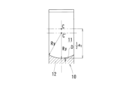
- the pocket 11 of the retainer 10 corresponds to the ball 5 with a diameter of ⁇ x (hereinafter referred to as the ball diameter ⁇ x).
- the inner surface of the pocket 11 is an inner surface (spherical surface) that draws an arc along the bearing radial direction, and its radius in the bearing radial direction is set to Ry. 2Ry is twice Ry and corresponds to the diameter in the bearing radial direction of the inner surface of the pocket 11.
- the center of the pocket 11 is the pocket center C
- the radius of the inner surface of the pocket 11 in a cross section that passes through the pocket center C and includes the bearing axis O is Ry
- the diameter is 2Ry (hereinafter referred to as the radial pocket diameter 2Ry).
- the pocket center C and the center of the ball 5 are coincident by design.
- FIG. 7 shows one cross section (first cross section) passing through the bearing centerline, but this radial pocket diameter 2Ry is set not only in the first cross section, but also in any cross section including the bearing radial line connecting the pocket center C and the bearing axis O (however, if a recess such as an oil reservoir is provided on the inner surface of the pocket 11, the location of that recess is excluded).
- the inner surface of the pocket 11, as shown in FIG. 8, is an inner surface (spherical surface) that draws an arc along the bearing circumferential direction, and its diameter in the bearing circumferential direction is set to ⁇ z. That is, the diameter of the inner surface of the pocket 11 in a cross section (hereinafter referred to as the second cross section) that is perpendicular to the bearing radial line passing through the pocket center C at the pocket center C is ⁇ z (hereinafter referred to as the circumferential pocket diameter ⁇ z).
- FIG. 8 shows one cross section (second cross section) that passes through the pocket center C and is perpendicular to the bearing radial line connecting the pocket center C and the bearing axis O, but this circumferential pocket diameter ⁇ z is set not only in the second cross section but also in any cross section that intersects with the bearing radial direction and passes through the pocket center C (however, if a recess H such as an oil reservoir is provided on the inner surface of the pocket 11, the location of the recess H is excluded).
- a recess H such as an oil reservoir
- the dimensional relationship between the ball diameter ⁇ x of the ball 5, the radial pocket diameter 2Ry on the inner surface of the pocket 11, and the circumferential pocket diameter ⁇ z is as follows: ⁇ x ⁇ 2Ry ⁇ z It is set so that:
- the radial pocket diameter 2Ry (see FIG. 7) and the circumferential pocket diameter ⁇ z (see FIG. 8) of the pocket 11 are not larger than the ball diameter ⁇ x, which is the diameter of the balls 5, the pocket 11 will tightly hold the balls 5, and the cage 10 will not function. For this reason, the requirements ⁇ x ⁇ 2Ry and ⁇ x ⁇ z are required.
- D indicates the bearing radial arc surface D with a diameter of 2Ry
- d1 indicates its inner diameter end d1
- d2 indicates its outer diameter end d2.
- E indicates the bearing circumferential arc surface E with a diameter of ⁇ z
- F indicates its bottom F.
- G indicates the tip G of the retaining claw 14.
- the radial pocket diameter 2Ry of the pocket 11 is too large, the radial play between the balls 5 and the cage 10 will increase, making interference between the cage 10 and the surrounding components (the inner ring 3, the outer ring 4, etc.) more likely to occur. Furthermore, during high-speed rotation, the above-mentioned interference becomes more likely to occur due to the combined effect of centrifugal deformation. For this reason, it is not desirable to make 2Ry too large. The inventors of the present application have therefore confirmed that the requirement of 2Ry ⁇ ⁇ z is desirable. However, in order to suppress such interference, the cage 10 must be made of engineering plastic.
- FIG. 9A to 9C show the relationship between the cage and the balls.
- the difference in diameter (radius) of each arc and the positional relationship of the centers of the arcs are exaggerated.
- FIG. 9A is a schematic diagram of a cross section corresponding to FIG. 8, and shows that the bearing circumferential arc surface E, which is composed of an arc with a circumferential pocket diameter ⁇ z (radius (1/2) ⁇ ⁇ z), continues from the tip G of the retaining claw 14 through the bottom F of the pocket portion 11 to the tip G of the retaining claw 14 on the opposite side.
- FIG. 9B is a schematic diagram of a cross section I-I of FIG.
- FIG. 9A shows that the bearing radial arc surface D, which is composed of an arc with a radial pocket diameter 2Ry (radius Ry), continues from the outer diameter side end d2 to the inner diameter side end d1 at the bottom F of the pocket portion 11.
- Figure 9C is a cross section taken along II-II in Figure 9A, and like the cross section taken along I-I, it shows that the radial arc surface D of the bearing, which is formed by an arc with a radial pocket diameter of 2Ry (radius Ry), continues from the outer diameter end to the inner diameter end of the pocket portion 11.
- the center C' of the radial arc surface D of the bearing is set at a position eccentric from the pocket center C toward the radial arc surface D of the bearing. Note that recesses H such as oil reservoirs are not shown in Figures 9A to 9C.
- dmn ⁇ (D+d)/2 ⁇ n D: Bearing outer diameter (mm) d: bearing inner diameter (mm) n: rotation speed (rpm)
- the bearing 1 to be applied under high-speed conditions where the dmn value, as defined by the formula (1), is 700,000 or more at the maximum rotation speed.
- the intrusion of foreign matter of a size that may affect the bearing life can be suppressed.
- deformation of the cage 10 during high-speed operation can be suppressed, and foreign matter can be prevented from being caught between the cage 10 and the seal member 20.
- ⁇ z see Figure 8
- the axial play of the retainer 10 becomes large. If the axial play of the retainer 10 becomes large, there is a concern that it may interfere with the seal member 20 depending on the conditions of use. For this reason, it is desirable to ensure that the axial clearance between the seal member 20 and the retainer 10 is 0.1 mm or more, taking into consideration the axial play and deformation of the retainer 10 due to centrifugal force.
- the provision of the seal member 20 prevents foreign matter from entering the bearing internal space A, but there is still a possibility that small particles may enter through the gap 28.
- the gap 28 in the seal lip 21 it is possible to control the particle size of the foreign matter that enters the bearing internal space A, and prevent the adverse effects associated with the intrusion of foreign matter. For example, it is believed that foreign matter with a particle size of 0.050 mm or less does not affect the bearing life.
- the lubricant (lubricating oil) is supplied to the bearing internal space A from both the one axial end side and the other axial end side, so the contents of this invention have been described using as an example a double-sided seal configuration with the seal member 20 provided at the openings on both axial ends.
- a double-sided seal configuration in which the seal member 20 is provided only at the opening on the one axial end side may be adopted.
- the seal member 20 is set at the opening on the side where the lubricant (lubricating oil) is supplied. Also, in the case of a single-sided seal, it is preferable that the retainer 10 is inserted into the bearing internal space A from the anti-seal side where the seal member 20 is not provided.
- Table 1 shows the results of rapid acceleration and deceleration tests based on the amount of internal oil in a plastic crown cage.
- the seal member 20 is a contact seal, it is fluid lubricated during operation, so there is no need to ensure an inflow of lubricant (lubricating oil) more than necessary, and it can be seen that there is no problem even if an excessive amount of lubricant (lubricating oil) is avoided from entering the bearing internal space A, as in Tests No. 3 and No. 4 in Table 1 above.
- the retainer 10 is made of engineering plastic, but the material of the retainer 10 may contain at least engineering plastic.
- the rotating shaft is exemplified as the rotating shaft of a drive motor equipped in an electric transport device such as an electric vehicle, or the rotating shaft of a reducer or speed increaser equipped in such electric transport device, but the bearing 1 of this invention and a bearing device using the bearing 1 can also be applied to the support parts of rotating shafts in various other transport devices, industrial machines, etc.
- it can be applied to the rotating parts of shafts, constant velocity joints, propeller shafts, turbochargers, transmissions, and wheel bearings in the power transmission paths of various transport devices, or the support parts of rotating shafts in various machine tools, generators, etc.
- the elastic portion 24 of the sealing member 20 is rubber, and the rubber is vulcanized and bonded to the core metal 23, but the rubber may be integrated with the core metal 23 by a bonding method other than vulcanization bonding. Also, if the strength and durability of the sealing member 20 are ensured, a sealing member 20 consisting of only the elastic portion 24 without using a core metal 23 may be used. Furthermore, the material of the elastic portion 24 may be other than rubber, for example, a synthetic resin.
Landscapes
- Engineering & Computer Science (AREA)
- General Engineering & Computer Science (AREA)
- Mechanical Engineering (AREA)
- Physics & Mathematics (AREA)
- Fluid Mechanics (AREA)
- Rolling Contact Bearings (AREA)
- Sealing With Elastic Sealing Lips (AREA)
- Sealing Of Bearings (AREA)
- Sealing Devices (AREA)
Abstract
Description
D:ベアリング外径(mm)
d:ベアリング内径(mm)
n:回転数(rpm)
で規定されるdmn値が70万以上の環境下で使用される玉軸受において、前記保持器はエンジニアプラスチックを含む冠形保持器であり、前記玉の直径φx、前記ポケットのポケット中心を通り且つ軸受の軸心を含む断面における前記ポケットの内周面の半径Ry、前記ポケット中心を通る軸受半径方向直線に前記ポケット中心で直交する断面における前記ポケットの内周面の直径φzの寸法関係がφx<2Ry<φzであり、前記シール部材は、前記内輪及び外輪の一方に固定されるとともに他方に設定されたシール摺動面に摺接するシールリップを備え、前記シールリップは、周方向に並んだ複数の突起を有し、前記複数の突起は、周方向に隣り合う前記突起同士の間に隙間を生じさせ、且つ、軸受回転に伴って前記隙間から前記突起と前記シール摺動面間に引き摺り込まれる潤滑油の油膜によって前記シールリップ及び前記シール摺動面間を流体潤滑状態にすることが可能な態様で形成されているシール付玉軸受を採用した(構成1)。
φx<2Ry<φz
となるように設定されている。
dmn={(D+d)/2}×n
D:ベアリング外径(mm)
d:ベアリング内径(mm)
n:回転数(rpm)
で規定されるdmn値が、その最高回転数において70万以上となるような高速条件下で、軸受1の適用が可能となる。また、同時に、軸受寿命に影響のある大きさの異物の侵入も抑制できる。さらに、高速運転時の保持器10の変形を抑制し、保持器10とシール部材20との間に異物が噛み込むことも防止できる。

3 内輪
4 外輪
5 玉(転動体)
10 保持器
11 ポケット
20 シール部材
21 シールリップ
28 隙間
A 軸受内部空間
B シール摺動面
Claims (4)
- 内輪(3)及び外輪(4)と、前記内輪(3)及び前記外輪(4)との間に配置される玉(5)と、前記玉(5)を周方向に沿って保持するポケット(11)を有する保持器(10)と、前記内輪(3)及び外輪(4)の間に形成される軸受内部空間(A)の軸方向端部の開口を閉じるシール部材(20)とを備え、
dmn={(D+d)/2}×n
D:ベアリング外径(mm)
d:ベアリング内径(mm)
n:回転数(rpm)
で規定されるdmn値が70万以上の環境下で使用される玉軸受において、
前記保持器(10)はエンジニアプラスチックを含む冠形保持器であり、
前記玉(5)の直径φx、前記ポケット(11)のポケット中心(C)を通り且つ軸受の軸心(O)を含む断面における前記ポケット(11)の内周面の半径Ry、前記ポケット中心(C)を通る軸受半径方向直線に前記ポケット中心(C)で直交する断面における前記ポケット(11)の内周面の直径φzの寸法関係がφx<2Ry<φzであり、
前記シール部材(20)は、前記内輪(3)及び外輪(4)の一方に固定されるとともに他方に設定されたシール摺動面(B)に摺接するシールリップ(21)を備え、前記シールリップ(21)は、周方向に並んだ複数の突起(27)を有し、前記複数の突起(27)は、周方向に隣り合う前記突起(27)同士の間に隙間(28)を生じさせ、且つ、軸受回転に伴って前記隙間(28)から前記突起(27)と前記シール摺動面(B)間に引き摺り込まれる潤滑油の油膜によって前記シールリップ(21)及び前記シール摺動面(B)間を流体潤滑状態にすることが可能な態様で形成されているシール付玉軸受。 - 前記シールリップ(21)に、ニトリルゴム、アクリルゴム、フッ素ゴムの中から選択される単一の又は複数の素材を用いている請求項1に記載のシール付玉軸受。
- 前記軸受内部空間(A)への潤滑剤の供給が、軸方向一端側から軸方向他端側への一方向である場合に、前記シール部材(20)を軸方向一端側の開口にのみ設けている請求項1に記載のシール付玉軸受。
- 請求項1から3のいずれか一つに記載のシール付玉軸受を用い、電動輸送機器用の駆動モータ、減速機又は増速機が備える回転軸を前記玉軸受で支持している軸受装置。
Priority Applications (1)
| Application Number | Priority Date | Filing Date | Title |
|---|---|---|---|
| CN202480012798.3A CN120693466A (zh) | 2023-02-16 | 2024-02-13 | 带密封的球轴承及轴承装置 |
Applications Claiming Priority (2)
| Application Number | Priority Date | Filing Date | Title |
|---|---|---|---|
| JP2023-022456 | 2023-02-16 | ||
| JP2023022456A JP2024116700A (ja) | 2023-02-16 | 2023-02-16 | シール付玉軸受及び軸受装置 |
Publications (1)
| Publication Number | Publication Date |
|---|---|
| WO2024172012A1 true WO2024172012A1 (ja) | 2024-08-22 |
Family
ID=92419997
Family Applications (1)
| Application Number | Title | Priority Date | Filing Date |
|---|---|---|---|
| PCT/JP2024/004759 Ceased WO2024172012A1 (ja) | 2023-02-16 | 2024-02-13 | シール付玉軸受及び軸受装置 |
Country Status (3)
| Country | Link |
|---|---|
| JP (1) | JP2024116700A (ja) |
| CN (1) | CN120693466A (ja) |
| WO (1) | WO2024172012A1 (ja) |
Citations (7)
| Publication number | Priority date | Publication date | Assignee | Title |
|---|---|---|---|---|
| JP2004156687A (ja) * | 2002-11-06 | 2004-06-03 | Nsk Ltd | 冠型保持器およびそれを用いた玉軸受 |
| JP2004211870A (ja) * | 2003-01-08 | 2004-07-29 | Nsk Ltd | 玉軸受用保持器及び玉軸受 |
| JP2011241946A (ja) * | 2010-05-20 | 2011-12-01 | Nsk Ltd | 潤滑剤封入方法、及び、潤滑剤封入方法によって潤滑剤を封入した転がり軸受 |
| JP2020041659A (ja) * | 2018-09-13 | 2020-03-19 | Ntn株式会社 | 玉軸受 |
| JP2020046069A (ja) * | 2018-03-30 | 2020-03-26 | Ntn株式会社 | 樹脂製保持器及び転がり軸受 |
| JP2020133770A (ja) * | 2019-02-20 | 2020-08-31 | Ntn株式会社 | 玉軸受 |
| WO2022264910A1 (ja) * | 2021-06-14 | 2022-12-22 | Ntn株式会社 | シール付軸受 |
-
2023
- 2023-02-16 JP JP2023022456A patent/JP2024116700A/ja active Pending
-
2024
- 2024-02-13 WO PCT/JP2024/004759 patent/WO2024172012A1/ja not_active Ceased
- 2024-02-13 CN CN202480012798.3A patent/CN120693466A/zh active Pending
Patent Citations (7)
| Publication number | Priority date | Publication date | Assignee | Title |
|---|---|---|---|---|
| JP2004156687A (ja) * | 2002-11-06 | 2004-06-03 | Nsk Ltd | 冠型保持器およびそれを用いた玉軸受 |
| JP2004211870A (ja) * | 2003-01-08 | 2004-07-29 | Nsk Ltd | 玉軸受用保持器及び玉軸受 |
| JP2011241946A (ja) * | 2010-05-20 | 2011-12-01 | Nsk Ltd | 潤滑剤封入方法、及び、潤滑剤封入方法によって潤滑剤を封入した転がり軸受 |
| JP2020046069A (ja) * | 2018-03-30 | 2020-03-26 | Ntn株式会社 | 樹脂製保持器及び転がり軸受 |
| JP2020041659A (ja) * | 2018-09-13 | 2020-03-19 | Ntn株式会社 | 玉軸受 |
| JP2020133770A (ja) * | 2019-02-20 | 2020-08-31 | Ntn株式会社 | 玉軸受 |
| WO2022264910A1 (ja) * | 2021-06-14 | 2022-12-22 | Ntn株式会社 | シール付軸受 |
Also Published As
| Publication number | Publication date |
|---|---|
| CN120693466A (zh) | 2025-09-23 |
| JP2024116700A (ja) | 2024-08-28 |
Similar Documents
| Publication | Publication Date | Title |
|---|---|---|
| JP6523994B2 (ja) | シール付軸受 | |
| US10570962B2 (en) | Sealed bearing | |
| WO2016143786A1 (ja) | シール付軸受 | |
| JP2019074196A (ja) | シール付玉軸受 | |
| JP6786265B2 (ja) | シール付軸受 | |
| JP7691452B2 (ja) | シール付玉軸受及び軸受装置 | |
| JP2024116700A (ja) | シール付玉軸受及び軸受装置 | |
| WO2017150609A1 (ja) | シール付軸受及び玉軸受 | |
| KR20240022519A (ko) | 시일을 갖는 베어링 | |
| JP7758515B2 (ja) | 転がり軸受 | |
| JP7240975B2 (ja) | シール付軸受 | |
| JP7331053B2 (ja) | シール付軸受 | |
| JP7591958B2 (ja) | シール付軸受 | |
| JP6878052B2 (ja) | シール付転がり軸受 | |
| JP6797719B2 (ja) | オイルシール及びシール付軸受 | |
| JP6887046B2 (ja) | 円すいころ軸受 | |
| JP2025133934A (ja) | シール付軸受 | |
| JP6725264B2 (ja) | 円すいころ軸受 | |
| JP2025145731A (ja) | シール付軸受 | |
| JP2022139574A (ja) | シール付軸受 | |
| JP2018197586A (ja) | シール付転がり軸受 | |
| JP2018138797A (ja) | 玉軸受 | |
| JP2017155818A (ja) | 玉軸受 |
Legal Events
| Date | Code | Title | Description |
|---|---|---|---|
| 121 | Ep: the epo has been informed by wipo that ep was designated in this application |
Ref document number: 24756857 Country of ref document: EP Kind code of ref document: A1 |
|
| WWE | Wipo information: entry into national phase |
Ref document number: 202480012798.3 Country of ref document: CN |
|
| NENP | Non-entry into the national phase |
Ref country code: DE |
|
| WWP | Wipo information: published in national office |
Ref document number: 202480012798.3 Country of ref document: CN |
|
| 122 | Ep: pct application non-entry in european phase |
Ref document number: 24756857 Country of ref document: EP Kind code of ref document: A1 |