WO2024172007A1 - 廃棄物収容器 - Google Patents
廃棄物収容器 Download PDFInfo
- Publication number
- WO2024172007A1 WO2024172007A1 PCT/JP2024/004735 JP2024004735W WO2024172007A1 WO 2024172007 A1 WO2024172007 A1 WO 2024172007A1 JP 2024004735 W JP2024004735 W JP 2024004735W WO 2024172007 A1 WO2024172007 A1 WO 2024172007A1
- Authority
- WO
- WIPO (PCT)
- Prior art keywords
- opening
- container
- closing
- waste
- human presence
- Prior art date
- Legal status (The legal status is an assumption and is not a legal conclusion. Google has not performed a legal analysis and makes no representation as to the accuracy of the status listed.)
- Ceased
Links
Images



Classifications
-
- B—PERFORMING OPERATIONS; TRANSPORTING
- B65—CONVEYING; PACKING; STORING; HANDLING THIN OR FILAMENTARY MATERIAL
- B65F—GATHERING OR REMOVAL OF DOMESTIC OR LIKE REFUSE
- B65F1/00—Refuse receptacles; Accessories therefor
- B65F1/14—Other constructional features; Accessories
- B65F1/16—Lids or covers
- B65F1/1623—Lids or covers with means for assisting the opening or closing thereof, e.g. springs
- B65F1/1638—Electromechanically operated lids
-
- B—PERFORMING OPERATIONS; TRANSPORTING
- B65—CONVEYING; PACKING; STORING; HANDLING THIN OR FILAMENTARY MATERIAL
- B65F—GATHERING OR REMOVAL OF DOMESTIC OR LIKE REFUSE
- B65F1/00—Refuse receptacles; Accessories therefor
- B65F1/14—Other constructional features; Accessories
- B65F2001/1653—Constructional features of lids or covers
- B65F2001/1676—Constructional features of lids or covers relating to means for sealing the lid or cover, e.g. against escaping odors
-
- B—PERFORMING OPERATIONS; TRANSPORTING
- B65—CONVEYING; PACKING; STORING; HANDLING THIN OR FILAMENTARY MATERIAL
- B65F—GATHERING OR REMOVAL OF DOMESTIC OR LIKE REFUSE
- B65F2210/00—Equipment of refuse receptacles
- B65F2210/129—Deodorizing means
-
- B—PERFORMING OPERATIONS; TRANSPORTING
- B65—CONVEYING; PACKING; STORING; HANDLING THIN OR FILAMENTARY MATERIAL
- B65F—GATHERING OR REMOVAL OF DOMESTIC OR LIKE REFUSE
- B65F2210/00—Equipment of refuse receptacles
- B65F2210/168—Sensing means
Definitions
- the present invention relates to a waste container. More specifically, it relates to a waste container that can prevent odors from leaking to the outside from an inlet that is opened when disposing of waste.
- Garbage generated in daily life is collected on days designated by each local government, but must be stored in one's own garbage bin until collection day.
- household garbage such as food waste is stored for about 3-4 days at most, but as food waste gradually decays, it is prone to producing odors, especially in the summer.
- Patent Document 1 discloses a trash can that uses the pressure applied when closing the top lid to spray a deodorant into the main body. This means that the deodorant is sprayed every time the top lid is closed, reducing the generation of odors inside the trash can.
- the present invention was devised in light of the above points, and aims to provide a waste container that can prevent odors from diffusing to the outside from the opening that is opened when disposing of waste.
- the waste container of the present invention comprises a container having a specified opening, and a closure configured to be attached to the container so as to substantially block the opening, which is inserted into the container from the opening when attached to the container, has a hollow insertion portion having a specified input port, and an opening/closing member moves forward and backward along a guide portion to open and close the input port, the opening/closing member having an opening/closing portion that is housed inside the insertion portion when the input port is opened.
- the closure has an opening/closing section that can open and close the insertion port by the opening/closing member moving back and forth along the guide section, so that when opening and closing the insertion port, the opening/closing member moves back and forth along a set path (i.e., the guide section), and the forward and backward movement can be performed in a stable state. Also, because the forward and backward movement of the opening/closing member at the insertion port is stable, it is possible to prevent the air around the insertion port from being significantly disturbed.
- the closure has a hollow insertion section with a specified insertion opening, and an opening/closing section that is housed inside the insertion section when the opening/closing member opens the insertion opening.
- the inside of the insertion section that houses the opening/closing member is separated from the outside of the insertion section by the member that constitutes the insertion section. Therefore, even if the air inside the insertion section is disturbed, it does not affect the outside of the insertion section and no air disturbance occurs.
- the opening and closing member is not necessarily limited to being entirely housed within the insertion section.
- this case just as when the opening and closing member is entirely housed when entering or exiting, even if the air inside the insertion section is disturbed, this will not affect the outside of the insertion section and no air disturbance will occur.
- a container having a specified opening and a sealing body that can be attached to the container so as to substantially block the opening can prevent odors from inside the container from leaking out through the opening to the outside.
- the plug goes inside the container during attachment, making it stable and allowing the closure to be securely attached to the container.
- the inside of the insertion part that houses the opening and closing member is separated from the outside of the insertion part by a member made of the airtight material that constitutes the insertion part, so that even if the air inside the insertion part is disturbed slightly by opening and closing the insertion port, the outside of the insertion part is not affected and no air disturbance occurs, which is an enhanced effect. Also, even if the insertion part is exposed to the outside of the container, it is possible to prevent odors from inside the container from leaking to the outside through the insertion part.
- the opening and closing members are configured as a pair that move forward and backward in opposite directions, and the opposing edges of each opening and closing member are formed so that they can be fitted together, the two opening and closing members share the travel distance required to close the insertion port, thereby shortening the time required to open and close the insertion port, and since the edges fit together when the insertion port is closed by the opening and closing members, it is possible to prevent odors from within the container from leaking to the outside.
- the sealing body has a deodorizing section located near the insertion opening, it can efficiently deodorize odors coming up from inside the container.
- the deodorizing section is provided on the inner circumferential surface of the insertion section so that it protrudes inward, the area of the deodorizing section that comes into contact with the air (odor) inside the container is increased, making it easier for a wider area of the deodorizing section to come into contact with the odor rising from inside the container, resulting in even more efficient deodorization.
- the closing body has a human presence sensor for opening the input port and the deodorizing unit is located on the same side as the human presence sensor, the worker is usually in the vicinity of the human presence sensor in order to operate the human presence sensor, so the odor that attempts to flow from the input port toward the human presence sensor can be efficiently deodorized in advance by the deodorizing unit, so that the worker does not have to smell the odor.
- the container has a drain that can discharge wastewater, the wastewater generated from the waste inside the container can be discharged outside the container, thereby suppressing the generation of odors inside the container.
- the closure has a display that can show the timing when the inlet closes
- the timing can be visualized, which can encourage workers to act quickly, such as speeding up the process of putting in the waste.
- the closure has a display that can show the timing when the inlet closes
- the timing can be visualized, which can encourage workers to act quickly, such as speeding up the process of putting in the waste.
- it will not be necessary to open the inlet again, for example, because the inlet will close before the waste has been put in, which would require the inlet to be opened again, resulting in an increase in the number of times it is opened and closed, and taking longer than necessary.
- the closing body has a human presence sensor for opening the inlet, and the human presence sensor detects that the inlet is open, if the inlet is left open for a long time, the longer the time, the more time the worker has to carry out the inlet loading work and can finish before the inlet closes. This means that, for example, the inlet will not close before the waste has been loaded and it will be necessary to open it again, which would result in an increase in the number of times it is opened and closed and take more time than necessary.
- the closure has a human presence sensor for opening the loading port
- the human presence sensor can be switched between an operating mode in which the loading port opens when it detects a human presence, and a non-operating mode in which the loading port remains closed, by setting it to the non-operating mode, the human presence sensor can react when a worker is performing maintenance such as cleaning or disassembling and adjusting the container, preventing the worker from opening or closing the container unintentionally, or preventing injury to the worker or damage to the container from falling.
- the waste container according to the present invention can prevent odors from diffusing to the outside from the inlet that is opened when disposing of waste.
- FIG. 2 is an exploded perspective view of the trash can according to the embodiment of the present invention.
- FIG. FIG. 4 is a cross-sectional view of the drive unit taken along line AA in FIG. 3.
- 4 is a cross-sectional view of the drive unit taken along line BB in FIG. 3.
- trash can A which is an example of a waste container, is mainly composed of a roughly rectangular parallelepiped container 1 with an open top, and a closure 2 that is placed on top of the container 1 and attached.
- the container 1 is formed into a roughly rectangular parallelepiped shape with a height of about 60 cm, a width of about 30 cm, and a depth of about 30 cm. Note that the size and shape of the container 1 are not limited to this embodiment, and can be determined as desired. Also, for ease of explanation, when trash can A is set up, the direction in which the closure 2 is provided relative to the container 1 is referred to as "upward", and the direction in which the container 1 is provided relative to the closure 2 is referred to as "downward".
- An opening 10 is provided at the top of the container 1, and the sealing body 2 is attached so as to substantially block the opening 10 of the container 1. Odor-generating waste such as food waste is inserted through an inlet 22 (described below) provided in the sealing body 2, and passes through the opening 10 to be contained in the container 1.
- Attached to the container 1 is an inner lid portion 3 having a bag holding hole 30 to which a garbage bag, an example of a storage bag, can be attached.
- the bag holding hole 30 is formed to be approximately 19 cm long and 19 cm wide, and a rising portion 30a that rises to a height of approximately 2 cm is formed around the entire periphery of the bag holding hole 30.
- the size and shape of the inner lid portion 3 are not limited to those of this embodiment, and can be determined as desired.
- the inner lid 3 is formed narrower than the container 1, and when the inner lid 3 is attached to the container 1, gaps 31, 31 of approximately 4 cm width are formed between the inner lid 3 and the inner surface of the container 1 on both sides, as shown in FIG. 4.
- the inner lid 3 is also hung inside the container 1 by hanging portions 32, 32 that extend approximately 1 cm from the inner surface of the container 1 toward the center of the container 1.
- the means for hanging the inner lid 3 inside the container 1 is not limited to the embodiment in this example, and can be determined arbitrarily.
- the opening of the garbage bag below the inner lid portion 3 is pulled out through the bag holding hole 30 and inserted into the gaps 31, 31 on both sides of the inner lid portion 3 so as to cover the rising portion 30a. This causes the garbage bag to be hooked onto the inner lid portion 3.
- a bottom plate 4 having a drain hole 40 through which waste liquid generated within the container 1 can be discharged is attached to the bottom of the container 1.
- a drain lid 41 is attached to the drain hole 40, sealing the drain hole 40, so that waste liquid generated within the container 1 does not leak out of the container 1. Also, by removing the drain lid 41 from the drain hole 40, the waste liquid generated within the container 1 can be discharged outside the container 1.
- the closure 2 is composed of a base 20 and an insertion part 21 that can fit into the container 1.
- an inlet 22 for inserting waste is provided on the front surface 20A of the base 20, and an inlet frame 22a is provided along the edge of the inlet 22.
- An opening/closing part 23 that substantially blocks the inlet 22 is provided slidably and substantially in contact with the back surface 20B of the base 20.
- An operation panel 24 for operating the opening and closing operation of the opening/closing part 23 is provided on the upper surface of the inlet frame 22a (reference number omitted).
- the inlet frame 22a is formed in a roughly rectangular shape with a width of approximately 24 cm and a depth of approximately 24 cm, and the top surface of the inlet frame 22a is located approximately 1 cm higher than the front surface 20A of the closure body 2.
- the operation panel 24 is provided on the top surface of frame member 221 of the four frame members 221, 222, 223, and 224 that make up the inlet frame 22a. An operator approaches frame member 221 and operates the operation panel 24 to open the inlet 22 and insert waste through the inlet 22.
- the operation panel 24 is equipped with a human sensor 240 that detects human movement such as holding a hand over the device, a close button 241 for causing the pair of opening and closing members 233, 233 to close the input port 22, and an open button 242 for causing the pair of opening and closing members 233, 233 to open the input port 22.
- the pair of opening/closing members 233, 233 are moved toward the advance/retract opening 22c of the insertion section 21 via the drive unit 25 to open the insertion opening 22.
- the base 20 of the closure 2 is provided with five lights 26 for indicating the time from when the insertion port 22 is open to when it is closed.
- the lights 26 are not provided exposed on the front surface 20A of the base 20, but are provided inside the base 20. Therefore, the light emitted from the lights 26 can be seen through slits 27 provided on the front surface 20A of the base 20.
- the inlet 22 When the inlet 22 is fully open, the five lights 26 are lit.
- the inlet 22 remains open for approximately five seconds, and the lights 26 are turned off one by one from one end in sequence every second depending on the remaining time that the open state is to be maintained. This makes it possible to visualize the remaining time that the inlet 22 will remain open, encouraging workers to quickly inject waste into the inlet 22. This also reduces the number of times that the inlet is closed before the waste has been completely inserted, requiring it to be opened again. As a result of the inlet being opened and closed less frequently, odors can be prevented from leaking out to the outside.
- the pair of opening and closing members 233, 233 advance toward approximately the center of the slot 22 from the advance/retract opening 22c provided near the frame members 222, 224, and the slot 22 is closed.
- the human presence sensor 240 detects the operator's hand, and the input port 22 remains open for a few seconds longer. This allows the operator to easily adjust the time that the operator can input waste into the input port 22, and prevents the input port 22 from being opened again. In other words, since the input port 22 is not opened multiple times in one input opportunity, it is possible to prevent odors from inside the container 1 from leaking to the outside.
- the human presence sensor 240 is also structured to be switchable between an operating mode in which the input port 22 opens when human movement is detected, and a non-operating mode in which no human movement is detected and the input port 22 remains closed.
- the human presence sensor reacts when a worker performs maintenance such as cleaning or disassembling and adjusting the container, preventing the worker from opening or closing the container unintentionally, or from being injured or the container falling and being damaged.
- the insertion portion 21 is provided on the back surface 20B of the closure 2, and is formed in a frame shape of approximately 27.5 cm by 27.5 cm.
- the insertion portion 21 is placed and attached so that it is inserted into the container 1 through the opening 10 of the container 1.
- the closure 2 substantially blocks the opening 10, thereby preventing odors from inside the container 1 from leaking out to the outside.
- the opening/closing section 23 is made up of a pair of opening/closing members 233, 233 that move forward and backward in opposite directions from approximately the center of the input port 22.
- Each of the opening/closing members 233, 233 is provided with a slide plate 230, which is a plate material having a longitudinal direction, and is made up of a joint 231 that connects adjacent slide plates 230.
- each of the pair of opening/closing members 233, 233 is made up of five slide plates 230, but this is not limited to this and can be determined arbitrarily.
- the position of the edges 232, 232 that butt together when the pair of opening/closing members 233, 233 are closed is not limited to approximately the center of the inlet 22, but can be configured to be closed at any location, such as near the frame members 222, 224 of the inlet frame 22a.
- the joint 231 is made up of an axis member 231a and a bearing portion 231b, and the axis member 231a is arranged to be rotatable while sliding within the bearing portion 231b while being held by the bearing portion 231b.
- This allows the adjacent slide plates 230 of the opening/closing members 233, 233 to be connected together, and at the same time, the joint 231 allows the adjacent slide plates 230 to bend while changing their angle.
- the opposing edge portions 232, 232 of the pair of opening/closing members 233, 233 are formed so that they can come into close contact with each other when the insertion port 22 is closed.
- the edge portions 232, 232 are formed in a structure in which projections and recesses are formed so that they can fit into each other and come into close contact.
- the shape or fitting method of the edge portions 232, 232 is not limited to this, and a structure in which they are fitted into close contact via a packing material or the like is also possible.
- the insertion section 21 is composed of insertion members 21a, 21b and connecting members 21c, 21d.
- the insertion members 21a and 21b are arranged approximately parallel to the sliding plate 230 of the opening/closing section 23, and hang down to a length of approximately 10 cm.
- the connecting members 21c, 21d are arranged in a direction approximately perpendicular to the sliding plate 230, connect the insertion members 21a and 21b at the top, and hang down to a length of approximately 6 cm.
- the insertion members 21a, 21b are hollow, and are provided with storage spaces 210, 210 capable of housing a pair of opening/closing members 233, 233.
- the insert members 21a and 21b are inserted into the gaps 31, 31 between the inner lid portion 3 and the container 1.
- the upper parts of the outer surfaces of the insert members 21a and 21b are in almost intimate contact with the inner surface around the edge of the opening 10, but because the insert members 21a and 21b are tapered downward, they gradually move apart as they go downward. This allows the insert members 21a and 21b to be inserted into the gaps 31, 31 without difficulty.
- the portion where the outer surfaces of the insert members 21a and 21b are in almost intimate contact with the inner surface of the container 1 allows the closure 2 to almost block the opening 10 of the container 1.
- the garbage bag is fixed between the inner lid portion 3 and the insert members 21a and 21b, creating a structure that does not easily come off, and by securely fitting the container 1 and the closure 2 together, the closure 2 is attached in close contact with the container 1.
- the rising portion 30a of the bag holding hole 30 of the inner lid portion 3 fits into the inserting portion 21 along the inner peripheral surface 211 of the inserting portion 21.
- This not only inserts the closure 2 into the container 1, but also connects the waste passage 212 formed by the inner peripheral surface 211 of the inserting portion 21 through which the waste passes and the bag holding hole 30 of the inner lid portion 3.
- a garbage bag is attached to the bag holding hole 30, so the waste is securely contained in the garbage bag from the bag holding hole 30.
- the pair of opening/closing members 233, 233 retreat in opposite directions from approximately the center of the insertion port 22 along the guide portion 22b and enter the advance/retract opening 22c, and near the frame members 222, 224 of the insertion port frame 22a, the sliding plates 230 of the opening/closing members 233, 233 are bent by the joints 231 and are accommodated within the accommodation spaces 210, 210.
- the opening and closing members 233, 233 housed in the storage spaces 210, 210 are pulled out of the storage spaces 210, 210 so as to be stretched by the joints 231, and advance from the advance/retract opening 22c along the guide portion 22b. Then, at approximately the center of the insertion port 22, the edge portions 232, 232 of the opening and closing members 233, 233 engage, and the insertion port 22 is closed. In this way, the pair of opening and closing members 233, 233 engage with the gear wheels 253, 253, and move while deforming in a curved shape between the insertion port 22 and the storage spaces 210, 210, thereby opening and closing the insertion port 22.
- the guide portion 22b provided on the back surface 20B of the base 20 is formed in a substantially straight line and is provided substantially parallel to the back surface 20B.
- the pair of opening and closing members 233, 233 advance and retreat substantially horizontally along the guide portion 22b (movement path of the opening and closing members) provided on the back surface 20B of the substrate 20, and then advance and retreat while deforming into a curved shape near the frame members 222, 224, and advance and retreat in a substantially vertical direction within the storage space 210, 210.
- the pair of opening and closing members 233, 233 open and close the input port 22 along the guide portion 22b, and advance and retreat substantially parallel and horizontal to the back surface 20B, so that the odor within the storage body 1 is not significantly disturbed.
- the pair of opening and closing members 233, 233 move forward and backward within the housing 1 because the insertion portion 21 is inserted into the housing 1.
- the pair of opening and closing members 233, 233 are housed in the housing space 210, 210 through the entrance and exit port 22c, but since the housing space 210, 210 is made of an airtight material and is separated from the outside of the insertion portion 21 (i.e., the inside of the housing 1), the air inside the housing 1 is not disturbed even if the pair of opening and closing members 233, 233 move forward and backward within the housing space 210, 210. This makes it possible to prevent odors inside the housing 1 from leaking to the outside.
- the storage spaces 210, 210 are connected to the outside through the advance/retract opening 22c and are not airtight; however, when the pair of opening/closing members 233, 233 advance and retreat within the storage spaces 210, 210, air turbulence is contained within a predetermined range (i.e., no significant air turbulence is caused outside the storage spaces 210, 210), so odors within the storage body 1 can be similarly prevented from being disturbed and leaking out of the storage body 1 to the outside.
- the sealing body 2 is structured in such a way that the forward and backward movements of the opening and closing members 233, 233 make it difficult for odors within the container 1 to diffuse to the outside.
- connection member 21c is provided with a battery box BX and a switch SW, and by operating the switch, it is possible to supply or stop power to the operation panel 24 and the drive unit 25 described below.
- the operation panel 24 moves a pair of opening and closing members 233, 233 via the drive unit 25 to open and close the insertion port 22.
- the drive unit 25 is provided in the insertion unit 21 and is composed of a motor 250, a power transmission shaft 251, drive gears 252, 252, gear wheels 253, 253, and a driven shaft (not shown), and is disposed in the connection member 21c.
- the motor 250 rotates the power transmission shaft 251, and the gear wheels 253, 253 are rotated by the drive gears 252, 252 provided on both ends of the power transmission shaft 251, thereby moving the two opening and closing members 233, 233 forward and backward.
- circular rack gears 254, 254 are provided that share a common rotation center with the gear wheels 253, 253, and mesh with the drive gears 252, 252 on the inside (the side close to each other).
- the outer periphery of the gear wheels 253, 253 has an engagement recess 255 that meshes with the shaft member 231a of the joint 231 on the back surface of the opening and closing members 233, 233. Then, by forward and reverse rotation of the motor, the gear wheels 253, 253 rotate in opposite directions in sync with each other, moving the opening and closing members 233, 233 forward and backward in opposite directions.
- the gear wheels 253, 253 that move the opening and closing members 233, 233 are provided in pairs, attached to both ends of the driven shaft, and arranged inside the connecting member 21d.
- the power of the motor 250 is transmitted to the power transmission shaft 251 by the human sensor 240 or the open button 242 of the operation panel 24, and the gear wheels 253, 253 rotate via the drive gears 252, 252.
- the engagement recesses 255 of the gear wheels 253, 253 engage with the shaft members 231a of the opening/closing members 233, 233, causing the pair of opening/closing members 233, 233 to move forward and backward.
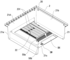
- the deodorizing section 5 is provided on the component surface 211a which constitutes part of the inner circumferential surface 211 of the insertion section 21.
- the component surface 211a is on the same side as the operation panel 24 (i.e., the inner circumferential surface of the connection member 21c of the inner circumferential surface 211, which is the surface through which the operation panel 24 passes when passing through the waste passage 212 from the frame member 221 on which the operation panel 24 is provided) or is located below (directly below) the operation panel 24.
- the deodorizing section 5 is composed of a box body 50 which contains a deodorant (not shown) inside, and a storage recess 51 which is provided on the inner circumferential surface 211 and can store the box body 50. When using the trash can A, the box body 50 is inserted into the storage recess 51.
- the front surface 50a and the bottom surface 50b of the box body 50 are provided with a plurality of ventilation holes 52, and odors that arise from the waste contained in the container 1 and rise inside the container 1 are deodorized by the deodorizing components leaking from the ventilation holes 52.
- the front surface 50a and the bottom surface 50b of the box body 50, on which the ventilation holes 52 are provided are provided protruding from the component surface 211a, the area of contact between the odor and the deodorant through the ventilation holes 52 is increased, thereby enhancing the deodorizing effect.
- the deodorizing section 5 is not limited to protruding from the inner circumferential surface 211, but may be embedded within the insertion section 21 with the front side surface being approximately flush with the component surface 211a.
- the trash can A having such a structure is provided on the closure 2, and waste is put into the trash can through the inlet 22 opened by a pair of opening and closing members 233, 233, thereby preventing the odor of the waste generated in the container 1 from easily leaking out to the outside.
- the worker stands in front of trash can A (i.e., near the frame member 221 of the input port 22) and, holding waste in his/her hand, brings his/her hand close to the human presence sensor 240 on the operation panel 24.
- the human presence sensor 240 detects the worker's hand, and the pair of opening/closing members 233, 233 are opened via the drive unit 25.
- the pair of opening/closing members 233, 233 move approximately horizontally near the insertion port 22, and after being inserted through the advance/retract port 22c, they curve while rotating along the gear wheels 253, 253, and hang down inside the insertion members 21a, 21b.
- the opening and closing members 233, 233 are stably advanced and retreated by the guide portion 22b, so they do not cause significant air disturbance within the container 1, and the surrounding air is not significantly disturbed when they advance and retreat within the storage spaces 210, 210.
- the odor within the container 1 is not disturbed by the movement of the pair of opening and closing members 233, 233, and it is possible to prevent odors from leaking to the outside when opening and closing.
- the opening/closing part 23 moves back and forth stably in the left-right direction to open and close, no significant air disturbance occurs inside the container 1 when opening and closing, so odors are prevented from leaking to the outside when opening and closing. Also, because the sliding plate 230 has a flat shape, the structure is such that air is less likely to be disturbed even when it moves back and forth.
- the deodorizing section 5 is provided on the component surface 211a of the insertion section 21, when the sealing body 2 is attached to the container 1, the deodorizing section 5 is disposed on the component surface 211a of the insertion section 21. Therefore, regardless of whether the input port 22 is open or closed, odors generated within the container 1 can be efficiently deodorized near the opening 10 through which the odors rise.
- the deodorizing section is provided on the surface opposite to component surface 211a, there is a high possibility that the waste will gain momentum toward the opposite surface and hit the deodorizing section on the opposite surface when inserted.
- the deodorizing section 5 is provided on component surface 211a of the insertion section 21, there is a low possibility that the waste will hit the deodorizing section 5 when inserted, and the deodorizing section 5 is less likely to come out of the storage recess 51.
- the deodorizing unit 5 is attached in a state where it protrudes from the component surface 211a, and there are ventilation holes on the front surface 50a and the bottom surface 50b of the box body 50 of the deodorizing unit 5, all of which are exposed, allowing the odor and the deodorant to come into contact efficiently, thereby improving the deodorizing efficiency.
- the deodorizing section 5 is provided on the component surface 211a of the insertion section 21, it is located in a position that is difficult for the operator to see, and therefore does not detract from the design of the trash can A.
- the inlet 22 is connected to the waste passage 212 of the insertion portion 21 and the bag holding hole 30 of the inner lid portion 3, waste inserted through the inlet 22 can be securely stored in the garbage bag.
- the waste container according to the present invention is a waste container that can prevent odors from diffusing to the outside from the inlet that is opened and closed when disposing of waste.
- Garbage can (waste container) 1 Container 10 Opening 2 Closure 21 Insertion section 211 Inner circumferential surface 22 Insertion port 22b Guide section 23 Opening/closing section 232, 232 Edge section 233, 233 Pair of opening/closing members 240 Human sensor 26 Lighting device (display section) 40 Drain hole 5 Deodorizing section
Landscapes
- Engineering & Computer Science (AREA)
- Mechanical Engineering (AREA)
- Refuse Receptacles (AREA)
Priority Applications (2)
| Application Number | Priority Date | Filing Date | Title |
|---|---|---|---|
| EP24756852.0A EP4667385A1 (en) | 2023-02-15 | 2024-02-13 | Waste container |
| CN202480012944.2A CN120693291A (zh) | 2023-02-15 | 2024-02-13 | 废品容器 |
Applications Claiming Priority (2)
| Application Number | Priority Date | Filing Date | Title |
|---|---|---|---|
| JP2023-021840 | 2023-02-15 | ||
| JP2023021840A JP7643743B2 (ja) | 2023-02-15 | 2023-02-15 | 廃棄物収容器 |
Publications (1)
| Publication Number | Publication Date |
|---|---|
| WO2024172007A1 true WO2024172007A1 (ja) | 2024-08-22 |
Family
ID=92420173
Family Applications (1)
| Application Number | Title | Priority Date | Filing Date |
|---|---|---|---|
| PCT/JP2024/004735 Ceased WO2024172007A1 (ja) | 2023-02-15 | 2024-02-13 | 廃棄物収容器 |
Country Status (4)
| Country | Link |
|---|---|
| EP (1) | EP4667385A1 (https=) |
| JP (1) | JP7643743B2 (https=) |
| CN (1) | CN120693291A (https=) |
| WO (1) | WO2024172007A1 (https=) |
Citations (5)
| Publication number | Priority date | Publication date | Assignee | Title |
|---|---|---|---|---|
| JPH05270604A (ja) * | 1992-03-26 | 1993-10-19 | Matsushita Electric Works Ltd | ごみ箱 |
| US20080264942A1 (en) * | 2007-04-30 | 2008-10-30 | Michael Tin-Kim Shek | Induction activated cover assembly for container |
| JP3159649U (ja) | 2010-03-10 | 2010-05-27 | 柯 文雄 | ゴミ箱 |
| JP3166217U (ja) * | 2010-12-11 | 2011-02-24 | 平野 昇 | 滅菌、抗菌、消臭ごみ箱 |
| US20110056952A1 (en) * | 2009-09-09 | 2011-03-10 | David Borowski | Waste Collection Device, and Waste Recycling System |
-
2023
- 2023-02-15 JP JP2023021840A patent/JP7643743B2/ja active Active
-
2024
- 2024-02-13 CN CN202480012944.2A patent/CN120693291A/zh active Pending
- 2024-02-13 WO PCT/JP2024/004735 patent/WO2024172007A1/ja not_active Ceased
- 2024-02-13 EP EP24756852.0A patent/EP4667385A1/en active Pending
Patent Citations (5)
| Publication number | Priority date | Publication date | Assignee | Title |
|---|---|---|---|---|
| JPH05270604A (ja) * | 1992-03-26 | 1993-10-19 | Matsushita Electric Works Ltd | ごみ箱 |
| US20080264942A1 (en) * | 2007-04-30 | 2008-10-30 | Michael Tin-Kim Shek | Induction activated cover assembly for container |
| US20110056952A1 (en) * | 2009-09-09 | 2011-03-10 | David Borowski | Waste Collection Device, and Waste Recycling System |
| JP3159649U (ja) | 2010-03-10 | 2010-05-27 | 柯 文雄 | ゴミ箱 |
| JP3166217U (ja) * | 2010-12-11 | 2011-02-24 | 平野 昇 | 滅菌、抗菌、消臭ごみ箱 |
Non-Patent Citations (1)
| Title |
|---|
| See also references of EP4667385A1 |
Also Published As
| Publication number | Publication date |
|---|---|
| JP2024115928A (ja) | 2024-08-27 |
| CN120693291A (zh) | 2025-09-23 |
| EP4667385A1 (en) | 2025-12-24 |
| JP7643743B2 (ja) | 2025-03-11 |
Similar Documents
| Publication | Publication Date | Title |
|---|---|---|
| CN113727601A (zh) | 自动宠物砂装置 | |
| CN108903348B (zh) | 一种智能家居鞋柜 | |
| US4846104A (en) | Automated cat toilet | |
| CN101346292B (zh) | 尿布桶 | |
| WO2011097497A1 (en) | Litter box with removable filter housing | |
| US20140117114A1 (en) | Hygiene Product Disposal Apparatus and Method of Use | |
| US20180325073A1 (en) | Pet defecation apparatus | |
| CN111169840A (zh) | 一种垃圾分类用自动打包套袋垃圾桶 | |
| KR101254750B1 (ko) | 악취물 수집 보관용 콘테이너 | |
| JP7643743B2 (ja) | 廃棄物収容器 | |
| KR20130044804A (ko) | 악취제거 및 살균이 가능한 음식물 쓰레기통 | |
| GB2333021A (en) | Insect trap | |
| EP3878770B1 (en) | Wastebasket having airtight means for preventing leakage of foul odors | |
| KR20160110015A (ko) | 생리대용 휴지통 | |
| KR20090028333A (ko) | 탈취용 음식물 쓰레기통 | |
| KR101544711B1 (ko) | 다중 지퍼백이 구비된 음식물 쓰레기봉투 | |
| CN223162458U (zh) | 一种垃圾桶 | |
| KR102724636B1 (ko) | 음식물 쓰레기 처리장치 | |
| CN218464552U (zh) | 一种具有消毒除味的移动连体式垃圾站 | |
| CN216314636U (zh) | 一种拼接式双层封闭长踏板猫砂盆 | |
| KR101512677B1 (ko) | 악취제거용 크린룸 | |
| CN2345510Y (zh) | 一种保洁垃圾箱 | |
| CN224014529U (zh) | 一种多功能垃圾桶 | |
| CN211811419U (zh) | 一种具有除臭功能的垃圾分类回收站 | |
| KR20140101555A (ko) | 음식물 쓰레기통 |
Legal Events
| Date | Code | Title | Description |
|---|---|---|---|
| 121 | Ep: the epo has been informed by wipo that ep was designated in this application |
Ref document number: 24756852 Country of ref document: EP Kind code of ref document: A1 |
|
| WWE | Wipo information: entry into national phase |
Ref document number: 202517075265 Country of ref document: IN |
|
| WWE | Wipo information: entry into national phase |
Ref document number: 202480012944.2 Country of ref document: CN |
|
| WWP | Wipo information: published in national office |
Ref document number: 202517075265 Country of ref document: IN |
|
| WWE | Wipo information: entry into national phase |
Ref document number: 2025125184 Country of ref document: RU Ref document number: 2024756852 Country of ref document: EP |
|
| NENP | Non-entry into the national phase |
Ref country code: DE |
|
| WWP | Wipo information: published in national office |
Ref document number: 202480012944.2 Country of ref document: CN |
|
| WWP | Wipo information: published in national office |
Ref document number: 2025125184 Country of ref document: RU |
|
| ENP | Entry into the national phase |
Ref document number: 2024756852 Country of ref document: EP Effective date: 20250915 |
|
| WWP | Wipo information: published in national office |
Ref document number: 2024756852 Country of ref document: EP |