WO2024171603A1 - バスバーモジュール、および、電池パック - Google Patents
バスバーモジュール、および、電池パック Download PDFInfo
- Publication number
- WO2024171603A1 WO2024171603A1 PCT/JP2023/045312 JP2023045312W WO2024171603A1 WO 2024171603 A1 WO2024171603 A1 WO 2024171603A1 JP 2023045312 W JP2023045312 W JP 2023045312W WO 2024171603 A1 WO2024171603 A1 WO 2024171603A1
- Authority
- WO
- WIPO (PCT)
- Prior art keywords
- solder
- connection piece
- guide
- substrate
- guide surface
- Prior art date
- Legal status (The legal status is an assumption and is not a legal conclusion. Google has not performed a legal analysis and makes no representation as to the accuracy of the status listed.)
- Ceased
Links
Images






Classifications
-
- H—ELECTRICITY
- H01—ELECTRIC ELEMENTS
- H01M—PROCESSES OR MEANS, e.g. BATTERIES, FOR THE DIRECT CONVERSION OF CHEMICAL ENERGY INTO ELECTRICAL ENERGY
- H01M50/00—Constructional details or processes of manufacture of the non-active parts of electrochemical cells other than fuel cells, e.g. hybrid cells
- H01M50/50—Current conducting connections for cells or batteries
- H01M50/502—Interconnectors for connecting terminals of adjacent batteries; Interconnectors for connecting cells outside a battery casing
- H01M50/507—Interconnectors for connecting terminals of adjacent batteries; Interconnectors for connecting cells outside a battery casing comprising an arrangement of two or more busbars within a container structure, e.g. busbar modules
-
- H—ELECTRICITY
- H01—ELECTRIC ELEMENTS
- H01M—PROCESSES OR MEANS, e.g. BATTERIES, FOR THE DIRECT CONVERSION OF CHEMICAL ENERGY INTO ELECTRICAL ENERGY
- H01M50/00—Constructional details or processes of manufacture of the non-active parts of electrochemical cells other than fuel cells, e.g. hybrid cells
- H01M50/20—Mountings; Secondary casings or frames; Racks, modules or packs; Suspension devices; Shock absorbers; Transport or carrying devices; Holders
- H01M50/204—Racks, modules or packs for multiple batteries or multiple cells
-
- H—ELECTRICITY
- H01—ELECTRIC ELEMENTS
- H01M—PROCESSES OR MEANS, e.g. BATTERIES, FOR THE DIRECT CONVERSION OF CHEMICAL ENERGY INTO ELECTRICAL ENERGY
- H01M50/00—Constructional details or processes of manufacture of the non-active parts of electrochemical cells other than fuel cells, e.g. hybrid cells
- H01M50/20—Mountings; Secondary casings or frames; Racks, modules or packs; Suspension devices; Shock absorbers; Transport or carrying devices; Holders
- H01M50/204—Racks, modules or packs for multiple batteries or multiple cells
- H01M50/207—Racks, modules or packs for multiple batteries or multiple cells characterised by their shape
- H01M50/209—Racks, modules or packs for multiple batteries or multiple cells characterised by their shape adapted for prismatic or rectangular cells
-
- H—ELECTRICITY
- H01—ELECTRIC ELEMENTS
- H01M—PROCESSES OR MEANS, e.g. BATTERIES, FOR THE DIRECT CONVERSION OF CHEMICAL ENERGY INTO ELECTRICAL ENERGY
- H01M50/00—Constructional details or processes of manufacture of the non-active parts of electrochemical cells other than fuel cells, e.g. hybrid cells
- H01M50/20—Mountings; Secondary casings or frames; Racks, modules or packs; Suspension devices; Shock absorbers; Transport or carrying devices; Holders
- H01M50/204—Racks, modules or packs for multiple batteries or multiple cells
- H01M50/207—Racks, modules or packs for multiple batteries or multiple cells characterised by their shape
- H01M50/211—Racks, modules or packs for multiple batteries or multiple cells characterised by their shape adapted for pouch cells
-
- H—ELECTRICITY
- H01—ELECTRIC ELEMENTS
- H01M—PROCESSES OR MEANS, e.g. BATTERIES, FOR THE DIRECT CONVERSION OF CHEMICAL ENERGY INTO ELECTRICAL ENERGY
- H01M50/00—Constructional details or processes of manufacture of the non-active parts of electrochemical cells other than fuel cells, e.g. hybrid cells
- H01M50/50—Current conducting connections for cells or batteries
-
- H—ELECTRICITY
- H01—ELECTRIC ELEMENTS
- H01M—PROCESSES OR MEANS, e.g. BATTERIES, FOR THE DIRECT CONVERSION OF CHEMICAL ENERGY INTO ELECTRICAL ENERGY
- H01M50/00—Constructional details or processes of manufacture of the non-active parts of electrochemical cells other than fuel cells, e.g. hybrid cells
- H01M50/50—Current conducting connections for cells or batteries
- H01M50/502—Interconnectors for connecting terminals of adjacent batteries; Interconnectors for connecting cells outside a battery casing
- H01M50/503—Interconnectors for connecting terminals of adjacent batteries; Interconnectors for connecting cells outside a battery casing characterised by the shape of the interconnectors
-
- H—ELECTRICITY
- H01—ELECTRIC ELEMENTS
- H01M—PROCESSES OR MEANS, e.g. BATTERIES, FOR THE DIRECT CONVERSION OF CHEMICAL ENERGY INTO ELECTRICAL ENERGY
- H01M50/00—Constructional details or processes of manufacture of the non-active parts of electrochemical cells other than fuel cells, e.g. hybrid cells
- H01M50/50—Current conducting connections for cells or batteries
- H01M50/502—Interconnectors for connecting terminals of adjacent batteries; Interconnectors for connecting cells outside a battery casing
- H01M50/514—Methods for interconnecting adjacent batteries or cells
- H01M50/516—Methods for interconnecting adjacent batteries or cells by welding, soldering or brazing
-
- Y—GENERAL TAGGING OF NEW TECHNOLOGICAL DEVELOPMENTS; GENERAL TAGGING OF CROSS-SECTIONAL TECHNOLOGIES SPANNING OVER SEVERAL SECTIONS OF THE IPC; TECHNICAL SUBJECTS COVERED BY FORMER USPC CROSS-REFERENCE ART COLLECTIONS [XRACs] AND DIGESTS
- Y02—TECHNOLOGIES OR APPLICATIONS FOR MITIGATION OR ADAPTATION AGAINST CLIMATE CHANGE
- Y02E—REDUCTION OF GREENHOUSE GAS [GHG] EMISSIONS, RELATED TO ENERGY GENERATION, TRANSMISSION OR DISTRIBUTION
- Y02E60/00—Enabling technologies; Technologies with a potential or indirect contribution to GHG emissions mitigation
- Y02E60/10—Energy storage using batteries
Definitions
- the disclosure herein relates to busbar modules and battery packs.
- Patent Document 1 describes a battery assembly to which a busbar module is attached.
- the busbar module is made of a flexible substrate and has a circuit body to which busbars are attached that are connected to the positive and negative electrodes of the cells.
- the circuit body has a main line arranged along the stacking direction on each cell, and a band-shaped first branch line portion that extends in a direction intersecting the longitudinal and thickness directions of the main line.
- a band-shaped second branch line portion is provided at the tip of the first branch line portion and extends in a direction parallel to the stacking direction of each battery body.
- a connection piece that protrudes from the busbar body toward the main line is fixed to the second branch line portion.
- connection piece is fixed to the connection part at the tip of the second branch line via solder.
- Solder is provided at the boundary between the connection part and the connection piece.
- the solder is attached to the outer surface of the connection piece so as to follow the edge of the connection piece. Because the amount of adhesion between the solder and the connection piece is small, if stress is applied to the solder, the strength of the solder may be insufficient and the solder may be damaged, making it impossible to maintain the connection between the connection piece and the connection part.
- the objective of this disclosure is to provide a busbar module and a battery pack in which the connection between the substrate and the connection piece is likely to be maintained even if stress is applied to the solder.
- a busbar module includes: A busbar module provided on electrode surfaces of a plurality of battery cells stacked in a thickness direction, A substrate; a busbar body connected to an electrode terminal that is connected to an electrode of a battery cell; and a plurality of busbars each having a connection piece extending from the busbar body to overlap the substrate and to be connected to the substrate; and solder for fixing the substrate and the connection piece, A guide structure having a guide surface along which the solder is guided is provided on the connecting piece, Solder is attached to at least a portion of the continuous surface that forms the outer shell of the connection piece and is continuous with the guide surface, and to the guide surface.
- the solder adheres to both at least a portion of the continuous surface and the guide surface, the amount of solder adhered to the connection piece is increased. This strengthens the connection between the board and the connection piece. Even if stress is applied to the solder, the connection between the board and the connection piece is likely to be maintained.
- a battery pack includes: A plurality of battery cells stacked in a thickness direction; a bus bar module provided on electrode surfaces of the plurality of battery cells;
- the busbar module is A substrate; a busbar body connected to an electrode terminal that is connected to an electrode of a battery cell; and a plurality of busbars each having a connection piece extending from the busbar body to overlap the substrate and to be connected to the substrate; and solder for fixing the substrate and the connection piece,
- a guide structure having a guide surface along which the solder is guided is provided on the connecting piece, Solder is attached to at least a portion of the continuous surface that forms the outer shell of the connection piece and is continuous with the guide surface, and to the guide surface.
- the battery pack has a busbar module. Since the solder adheres to both at least a portion of the continuous surface and the guide surface, the amount of solder adhered to the connection piece is increased. This strengthens the connection between the board and the connection piece. Even if stress is applied to the solder, the connection between the board and the connection piece is likely to be maintained.
- FIG. FIG. 2 is a perspective view of the battery pack with the case removed.
- FIG. 2 is a perspective view of the bus bar module excluding the holder.
- 4 is a perspective view showing a connection relationship between a terminal portion and a connection piece.
- FIG. FIG. 2 is an enlarged view of a connection portion between a terminal portion and a connection piece;
- FIG. 4 is a schematic diagram illustrating one of the guide structures of the first embodiment.
- 10 is a schematic diagram illustrating another guide structure in the first embodiment.
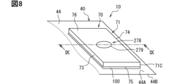
- FIG. 13A and 13B are schematic diagrams illustrating a guide structure in a second embodiment.
- FIG. 11 is a cross-sectional view illustrating a guide structure according to a second embodiment.
- FIGS. 13A and 13B are cross-sectional views illustrating a modified example of the guide structure of the second embodiment.
- 13A and 13B are schematic diagrams illustrating a guide structure according to a third embodiment.
- FIG. 11 is a cross-sectional view illustrating a guide structure according to a third embodiment.
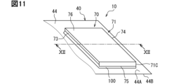
- 13A and 13B are schematic diagrams illustrating a guide structure according to a fourth embodiment.
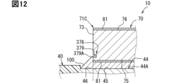
- FIG. 13 is a cross-sectional view illustrating a guide structure according to a fourth embodiment.
- FIG. 1 shows a schematic diagram of various components of the battery pack 1.
- Figs. 2 to 7 show a schematic diagram of various components of the bus bar module 10.
- the battery pack 1 of the embodiment is applied to an electric vehicle such as an electric vehicle or a plug-in hybrid vehicle, for example.
- the battery pack 1 includes a plurality of battery cells 20.
- the battery cells 20 are secondary batteries. Secondary batteries that can be used for the battery cells 20 include, for example, lithium ion secondary batteries, nickel-metal hydride secondary batteries, and organic radical batteries. These secondary batteries generate electromotive voltage through chemical reactions.
- the thickness direction of the battery cell 20 may be referred to as the thickness direction TD.
- the thickness direction TD corresponds to the stacking direction of the multiple battery assemblies 21.
- the width direction of the battery cell 20 may be referred to as the width direction WD.
- the height direction of the battery cell 20 may be referred to as the height direction HT.
- the thickness direction TD, width direction WD, and height direction HT are mutually orthogonal.
- the thickness direction TD may be simply referred to as "TD”.
- the width direction WD may be simply referred to as "WD”.
- the height direction HT may be simply referred to as "HD”.
- Fig. 1 is an exploded perspective view of the battery pack 1.
- Fig. 2 is a perspective view of the battery pack 1 without the case 160.
- Fig. 3 is a perspective view of the bus bar module without the holder.
- Fig. 4 is a perspective view showing the connection relationship between the terminal portion 40 and the connection piece 70.
- Fig. 5 is an enlarged view of the connection point between the terminal portion 40 and the connection piece 70.
- Fig. 6 is a schematic diagram illustrating one of the guide structures 78 of the first embodiment.
- Fig. 7 is a schematic diagram illustrating another of the guide structures 78 of the first embodiment.
- the battery pack 1 is mounted on an electric vehicle and constitutes an on-board power supply.
- the on-board power supply serves to supply power to the electric loads of the vehicle.
- the on-board power supply may be located, for example, in the space under the front seats, the space under the rear seats, or the space between the rear seats and the trunk.
- the battery pack 1 includes a busbar module 10, a number of battery cells 20, a resin frame 110, a cover 120, nuts 130, end plates 140, shims 150, and a case 160 that houses these components.
- the case 160 will be described first.
- the case 160 has a bottomed box shape formed by die casting, for example. Aluminum or the like is used as the material of the case 160.
- the case 160 has a bottom wall 161 and a side wall 162.
- the bottom wall 161 and the side wall 162 are integrally connected.
- the bottom wall 161 has a flat shape with a small thickness in the height direction HT.
- the side wall 162 stands upright in the height direction HT from the inner bottom surface of the bottom wall 161.
- the side wall 162 extends along the edge of the inner bottom surface and forms an annular shape in the circumferential direction around the height direction HT.
- the bottom wall 161 and the side wall 162 form a storage space 163 of the case 160.
- a number of battery cells 20 are stored in the storage space 163.
- the battery cells 20 are stored in the storage space 163 in two rows in the width direction WD.
- the case 160 has an opening at one end in the height direction HT.
- the battery cells 20 are stored in the case 160 so that the electrode surfaces 20A of each battery cell 20 correspond to the opening side.
- the battery cells 20 are stacked in the thickness direction TD so that the main surfaces 20C overlap each other.
- the battery cell 20 has a generally rectangular parallelepiped shape with a small thickness in the thickness direction TD.
- the battery cell 20 has an electrode surface 20A having a positive electrode terminal 24 and a negative electrode terminal 25, and two main surfaces 20C along a plane perpendicular to the thickness direction TD.
- the electrode surface 20A is provided between the two main surfaces 20C so as to connect the two main surfaces 20C.
- the battery cell 20 has a positive electrode and a negative electrode at both ends of the electrode surface 20A in the width direction WD.
- the battery cells 20 are stacked in the thickness direction TD so that the positive electrodes and the negative electrodes are alternately arranged with respect to the thickness direction TD.
- a resin frame 110 is disposed between two adjacent ones of the stacked battery cells 20.
- the battery cells 20 and the resin frames 110 are alternately arranged in the stacking direction.
- the battery assembly 21 is formed by alternately stacking the battery cells 20 and the resin frames 110.
- the resin frame 110 is formed, for example, from a resin member having electrical insulation properties.
- the resin frame 110 is disposed between adjacent battery cells 20 as an insulating member.
- the resin frame 110 has a central body 111 that faces the main surface 20C of the battery cell 20, and a frame body 112 that is connected integrally to the periphery of the central body 111 and arranged in a ring shape.
- the battery cell 20 is housed in a space partitioned by the central body 111 and the frame body 112, and its position is fixed.
- a positive electrode terminal 24 that is electrically connected to the positive electrode and a negative electrode terminal 25 that is electrically connected to the negative electrode are provided on the wall of the frame body 112 that faces the electrode surface 20A.
- the positive electrode terminal 24 and the negative electrode terminal 25 may be collectively referred to as the electrode terminals 24, 25.
- an end plate 140 is attached from the outside to the battery cell 20 located at the end in the thickness direction TD so as to cover the battery cell 20.
- the end plate 140 is made of an electrically insulating resin material.
- a shim 150 is provided between the end plate 140 and the side wall 162 to adjust the relative positions of the various components.
- the shim 150 is made of a metal material.
- the bus bar module 10 is disposed above the battery assembly 21 so as to cover the electrode surfaces 20A of the multiple battery cells 20.
- the bus bar module 10 has a substrate 50, a bus bar 80, solder 100, and a holder 170.
- the substrate 50 is electrically connected to the electrode terminals 24, 25 of the battery cells 20 via the bus bar 80.
- the substrate 50 and the bus bar 80 are held and stored in the holder 170.
- the substrate 50 is a flexible substrate that can flexibly deform.
- a wiring pattern is provided on the substrate 50.
- a resin layer that covers the wiring pattern is provided on the front and back surfaces of the substrate 50.
- the substrate 50 has a base 30 and a plurality of terminal portions 40.
- the base 30 is provided above the battery assembly 21 so as to cover a region between the positive electrode terminal 24 and the negative electrode terminal 25 that are spaced apart in the width direction WD.
- the base 30 extends in the thickness direction TD.
- the electrode terminals 24, 25 are provided outside the base 30 in the width direction WD.
- the base 30 and the electrode terminals 24, 25 are spaced apart in the width direction WD.
- the base 30 is provided with a voltage detection line that detects the voltage of the battery cell 20.
- the multiple terminal portions 40 are provided at both ends of the base 30 in the width direction WD.
- the terminal portions 40 have a first extension portion 41 and a second extension portion 42.
- the first extension portion 41 extends in the width direction WD from an end portion of the base 30 in the width direction WD toward each of the electrode terminals 24, 25.
- the second extension portion 42 is provided at an end portion of the first extension portion 41 on the side away from the base 30.
- the second extension portion 42 is provided on an edge in the width direction WD of the end portion of the first extension portion 41 on the side away from the base 30.
- the second extension 42 extends away from the first extension 41 and toward the electrode surface 20A. It can also be said that the second extension 42 extends in the height direction HT toward the electrode surface 20A.
- the base 30 is provided above the electrode surface 20A by about the length of the second extension 42 in the height direction HT.
- the second extension 42 is bent in a roughly S-shape as it extends in the height direction HT toward the electrode surface 20A. It can also be said that the second extension 42 has two bent portions 42A that bend in opposite directions.
- the two bent portions 42A are continuously lined up in the height direction HT. One of the two bent portions 42A is bent in a mountain shape, and the other of the two bent portions 42A is bent in a valley shape.
- the substrate 50 is a flexible substrate. Therefore, the base 30, the first extension 41, and the second extension 42 are flexibly deformable.
- the base 30 and the first extension 41 are flexibly deformable, particularly in the height direction HT.
- the second extension 42 is flexibly deformable, particularly in the height direction HT and the thickness direction TD.
- the tip of the second extension 42 away from the first extension 41 extends in the thickness direction TD. It can also be said that the tip of the second extension 42 away from the first extension 41 has a length in the thickness direction TD.
- the second extension 42 has an axis 43 extending in the height direction HT away from the first extension 41, and a tip 44 extending in the thickness direction TD from the tip of the axis 43 away from the first extension 41.
- the tip portion 44 has a plate-like shape with a small thickness in the height direction HT.
- the tip portion 44 is provided between the base portion 30 and the battery assembly 21 in the height direction HT.
- the tip portion 44 is provided above the electrode surface 20A in the height direction HT.
- the tip portion 44 is a portion electrically connected to the electrode terminals 24, 25 via the bus bar 80.
- the tip portion 44 has a surface 44A located on the base portion 30 side and a back surface 44B on the back side thereof.
- the surface 44A is a surface to which the bus bar 80 is connected.
- the surface 44A extends flat along a plane perpendicular to the height direction HT.
- a connector 31 is also attached to the end of the base 30.
- the connector 31 is connected to a voltage detection line and can be connected to an external voltage detection device.
- the tip 44 is electrically connected to the electrode terminals 24, 25 via the bus bar 80, causing a current to flow through the voltage detection line.
- the current that has flowed through the voltage detection line flows through the connector 31 to the external voltage detection device.
- the voltage detection device detects the voltage of the battery cell 20 based on this current.
- the busbar 80 is a metal plate-shaped member that is flat in the height direction HT.
- the busbar 80 is made mainly of copper.
- the busbar 80 has a busbar body 60 and a connection piece 70 that protrudes from the busbar body 60.
- the busbar 80 is provided above the battery cell 20 so as to overlap the electrode surface 20A.
- the busbar body 60 is a portion that is electrically connected to the electrode terminals 24, 25.
- the connection piece 70 extends from the busbar body 60 toward the tip portion 44 in the width direction WD.
- the connection piece 70 is a portion that is electrically connected to the tip portion 44.
- the connection piece 70 may be a separate member from the busbar body 60.
- the busbar body 60 has two through holes 61 through which the positive electrode terminal 24 and the negative electrode terminal 25 adjacent in the thickness direction TD are passed.
- the positive electrode terminal 24 and the negative electrode terminal 25 pass through the two through holes 61.
- a nut 130 is passed through the positive electrode terminal 24 and the negative electrode terminal 25 from above the busbar body 60.
- the nut 130 is fixed to the positive electrode terminal 24 and the negative electrode terminal 25. This electrically and mechanically connects the electrode terminals 24, 25 to the busbar body 60.
- the terminal portion 40 is provided at the end of the base portion 30 in the width direction WD.
- the busbar 80 is provided on the outside of the terminal portion 40 in the width direction WD.
- the terminal portion 40 has a first extension portion 41 extending in the width direction WD from the end of the base portion 30 in the width direction WD, and a second extension portion 42 extending in the height direction HT from the end of the first extension portion 41.
- the second extension portion 42 has a shaft portion 43 extending in the height direction HT away from the first extension portion 41, and a tip portion 44 extending in the thickness direction TD from the tip of the shaft portion 43 away from the first extension portion 41.
- the busbar body 60 of the busbar 80 is provided on the electrode terminals 24 and 25.
- the connection piece 70 of the busbar 80 extends in the width direction WD from the busbar body 60 toward the tip portion 44.
- the connection piece 70 is connected to the tip portion 44 via the solder 100.
- the holder 170 is a holding and housing structure for holding and housing the substrate 50 and the bus bar 80.
- the holder 170 is formed of, for example, an electrically insulating resin.
- the holder 170 has a main body housing section 171, a terminal housing section 172, and a lid section 173.
- the main body housing section 171 is provided on the battery cell 20 side of the base section 30.
- the main body housing section 171 holds the base section 30 from below.
- the terminal housing sections 172 are provided at both ends of the main body housing section 171 in the width direction WD.
- the terminal section 40 is held and housed in the terminal housing section 172.
- the terminal section 40 is exposed from the terminal housing section 172.
- the substrate 50 is covered by a lid section 173 made of an electrically insulating resin on the opposite side of the main body housing section 171.
- a cover 120 made of an electrically insulating resin is attached to the holder 170.
- the cover 120 is attached from above the holder 170 to protect the live parts from the outside. By attaching the cover 120 to the holder 170 in this manner, contact between the connection portion between the tip portion 44 and the connection piece 70 and moisture or dust from the outside is prevented.
- connection piece 70 has a frame shape that forms a ring around the axis in the height direction HT.
- the connection piece 70 has a substantially rectangular shape when viewed in the height direction HT.
- the connection piece 70 has four edges 71 that form a frame.
- the edge 71 that continues from the busbar body 60 may be referred to as a first edge 71A.
- the edge 71 that is provided to face the first edge 71A may be referred to as a third edge 71C.
- the edge 71 that connects one end of the first edge 71A and one end of the third edge 71C may be referred to as a second edge 71B.
- the edge 71 that connects the other end of the first edge 71A and the other end of the third edge 71C may be referred to as a fourth edge 71D.
- the first edge 71A, the second edge 71B, the third edge 71C, and the fourth edge 71D are provided in this order clockwise on the busbar body 60.
- a space 72 is defined by the four edges 71. It can also be said that the space 72 is defined by inner surfaces 73 of the four edges 71.
- the battery pack 1 further includes a chip fuse 82.
- the chip fuse 82 is disposed in the space 72. Although details are omitted, wiring such as a voltage detection wiring provided on the base 30 is electrically connected to the connection piece 70 via the chip fuse 82.
- the four edge portions 71 have an outer side surface 74, an opposing surface 75, and an upper surface 76 in addition to the inner side surface 73.
- the connection piece 70 has an inner side surface 73, an outer side surface 74, an opposing surface 75, and an upper surface 76.
- the outer side surface 74 is a surface that is provided on the outer side of the inner side surface 73 in a direction perpendicular to the height direction HT.
- the opposing surface 75 is a surface that faces the surface 44A of the tip portion 44.
- the opposing surface 75 is a surface that is connected to one end of the inner side surface 73 in the height direction HT and one end of the outer side surface 74 in the height direction HT.
- the opposing surface 75 is a surface that is spaced apart from the surface 44A at a constant distance from the surface 44A in the height direction HT.
- the upper surface 76 is a surface that is connected to the other end of the inner side surface 73 in the height direction HT and the other end of the outer side surface 74 in the height direction HT.
- the outer side surface 74 of the first edge portion 71A is integrally connected to the busbar body 60.
- connection piece 70 is provided at the tip 44 so that the opposing surfaces 75 of the four edges 71 overlap the surface 44A in the height direction HT.
- Solder 100 is provided between the edges 71 and the tip 44.
- the connection piece 70 and the tip 44 are fixed via the solder 100.
- the surface 44A is sometimes referred to as the solder connection portion because it is the portion of the tip 44 where the solder 100 is connected. Note that the resin layer has been removed from the overlapping region 45 that overlaps the first edge 71A and the third edge 71C in the solder connection portion, and from the continuous region 46 that continues slightly from the overlapping region 45 toward the space 72 in the solder connection portion.
- Solder 100 is provided in the overlapping region 45 overlapping the first edge 71A and the third edge 71C, and in the continuous region 46 that continues slightly from the overlapping region 45 towards the space 72.
- the first edge 71A and the tip 44 are electrically connected and fixed by the solder 100 provided in the overlapping region 45 overlapping the first edge 71A and in the continuous region 46 that continues from the overlapping region 45.
- the third edge 71C and the tip 44 are electrically connected and fixed by the solder 100 provided in the overlapping region 45 overlapping the third edge 71C and in the continuous region 46 that continues from the overlapping region 45.
- the first edge 71A and the third edge 71C are spaced apart in the width direction WD. Therefore, it can be said that the connection piece 70 and the tip 44 are fixed by the solder 100 at two points spaced apart in the width direction WD. Also, since the solder 100 is provided in the continuous region 46, it can be said that the solder 100 is provided in a region outside the projection region of the edge 71 onto the surface 44A. Therefore, the solder 100 can be seen when viewed from the height direction HT.
- a guide structure 78 having a guide surface 79A along which the solder 100 is guided is provided on the inner side of the edge portion 71, which is on the side of the space 72.
- the guide structure 78 has a guide surface 79A that is connected to the opposing surface 75 and the inner surface 73.
- the guide structure 78 is an inclined portion 79 having an inclined surface that connects the opposing surface 75 and the inner surface 73 as the guide surface 79A. Note that the guide structure 78 is not limited to the inclined portion 79.
- the guide structure 78 may be a recess 279 recessed from the opposing surface 75, a recess 379 recessed from the inner surface 73, a curved portion 479 having a curved surface that connects the opposing surface 75 and the inner surface 73, or the like.
- the inclined portion 79 is inclined so that the guide surface 79A extends away from the surface 44A, which is the solder connection portion of the tip portion 44.
- the inclined portion 79 is inclined so as to approach the tip portion 44 as it moves from the inner surface 73 toward the outer surface 74.
- the inclined portion 79 is provided at an imaginary corner 77 formed when the inner surface 73 and the opposing surface 75 collide.
- the guide surface 79A is a surface that connects the inner surface 73 and the opposing surface 75.
- the opposing surface 75 overlaps the surface 44A of the terminal portion 40, and its end continues to the guide surface 79A.
- the inner surface 73 continues from the end of the guide surface 79A opposite to the end that continues to the opposing surface 75, and extends in the height direction HT so as to move away from the opposing surface 75.
- the guide structure 78 is formed on the first edge portion 71A and the third edge portion 71C. First, the guide structure 78 formed on the first edge portion 71A will be described.
- An inclined portion 79 is provided at a virtual corner portion 77 where the inner surface 73 and the opposing surface 75 of the first edge portion 71A collide.
- the guide surface 79A of the inclined portion 79 connects the inner surface 73 of the first edge portion 71A to the opposing surface 75 of the first edge portion 71A.
- the opposing surface 75 of the first edge portion 71A, the guide surface 79A of the inclined portion 79, and the inner surface 73 of the first edge portion 71A are continuous.
- Solder 100 is attached to the opposing surface 75 and the guide surface 79A.
- the solder 100 may also be attached to the inner surface 73 of the first edge portion 71A.
- the inner surface 73 and/or the opposing surface 75 are sometimes referred to as continuous surfaces 73, 75 because they are surfaces that are continuous with the guide surface 79A.
- the continuous surfaces 73, 75 are surfaces that form part of the outer shell of the connection piece 70.
- the outer shell refers to the outer surface excluding the guide surface 79A.
- the outer shell refers to the inner surface 73, the outer surface 74, the opposing surface 75, and the top surface 76.
- the solder 100 attached to the guide surface 79A of the first edge portion 71A curves smoothly and flares out toward the surface 44A.
- the flared solder 100 penetrates into the continuous region 46.
- the solder 100 attached to the guide surface 79A forms a fillet shape. This makes it easy to check the presence or absence of solder 100 when viewed from the height direction HT during inspection.
- an inclined portion 79 is provided at a virtual corner 77 where the inner surface 73 and the opposing surface 75 of the third edge portion 71C collide.
- a guide surface 79A of the inclined portion 79 connects the inner surface 73 of the third edge portion 71C to the opposing surface 75 of the third edge portion 71C.
- the opposing surface 75 of the third edge portion 71C, the guide surface 79A of the inclined portion 79, and the inner surface 73 of the third edge portion 71C are continuous.
- Solder 100 is attached to this opposing surface 75 and the guide surface 79A continuing from the opposing surface 75. Note that the solder 100 may be attached to the inner surface 73 of the third edge portion 71C in addition to the opposing surface 75 of the third edge portion 71C and the guide surface 79A continuing from this opposing surface 75.
- the inner surface 73 and/or the opposing surface 75 are also referred to as continuous surfaces 73, 75 because they are surfaces that continue to the guide surface 79A.
- the continuous surfaces 73, 75 are surfaces that form the outer shell of the connection piece 70.
- the solder 100 attached to the guide surface 79A of the third edge portion 71C smoothly curves and flares out toward the surface 44A.
- the flared solder 100 penetrates into the continuous region 46.
- the solder 100 attached to the guide surface 79A forms a fillet shape. This makes it easy to check the presence or absence of solder 100 when viewed from the height direction HT during inspection.
- the busbar module 10 further has a metal film 81 for improving the wetting and spreading of the solder 100.
- An example of the metal film 81 is plating.
- the metal film 81 is provided on the four edges 71 of the connection piece 70.
- the metal film 81 is provided on the opposing surface 75, the top surface 76, and the guide surface 79A of the four edges 71. Note that the metal film 81 does not have to be provided on the guide surface 79A.
- busbars are formed by punching out a sheet of metal such as copper, which has a metal film such as plating applied to its surface, in the thickness direction.
- a metal film such as plating applied to its surface
- the base metal such as copper, which has no metal film applied
- the solder wettability and spreadability is inferior on fracture surfaces compared to surfaces with a metal film. For this reason, even if you want to apply solder to the fracture surface, the solder has difficulty creeping up to the fracture surface, and there was a concern that it would be difficult to apply solder over a wide area of the fracture surface.
- the corners 77 connecting the facing surface 75 and the inner surface 73 of the busbar 80 are crushed to form inclined portions 79 as guide structures 78.
- the process of crushing the corners 77 to form the inclined portions 79 as guide structures 78 is also called C-face stamping.
- a guide surface 79A originating from the facing surface 75 is formed on at least a portion of the inclined portion 79.
- a metal film can be provided on at least a portion of the guide surface 79A. This can improve the wetting and spreading of the solder 100 on the guide surface 79A.
- the amount of solder 100 adhering to the connection piece 70 can be increased.
- the shape of the connecting piece 70 is not limited to a frame shape.
- the connecting piece 70 may be in a plate shape with the space 72 closed.
- the connecting piece 70 has an opposing surface 75, an upper surface 76, and an outer surface 74.
- an inclined portion 79 is provided at an imaginary corner 77 where the opposing surface 75 and the outer surface 74 of the connecting piece 70 meet.
- Solder 100 adheres to the opposing surface 75 and the guide surface 79A. Even in this case, solder 100 may also adhere to the outer surface 74. The amount of solder 100 adhered to the connecting piece 70 can be increased.
- the busbar module 10 of this embodiment has a substrate 50, a busbar 80, and solder 100.
- the substrate 50 has a base 30 and a plurality of terminal portions 40 extending from the base 30 toward the electrode terminals 24, 25 of the plurality of battery cells 20.
- the busbar 80 has a busbar main body 60 connected to the electrode terminals 24, 25, and a connection piece 70 extending from the busbar main body 60 and connected to the terminal portion 40.
- the terminal portion 40 and the connection piece 70 overlap in the height direction HT of the battery cell 20, and the connection piece 70 and the terminal portion 40 are fixed by the solder 100.
- the substrate 50 does not need to have the terminal portion 40.
- the substrate 50 may have only the base 30. In that case, the connection piece 70 and the base 30 are fixed by the solder 100.
- the connecting piece 70 is formed with a guide structure 78 having a guide surface 79A along which the solder 100 is guided.
- the solder 100 forms part of the outer shell of the connecting piece 70 and is attached to continuous surfaces 73, 75 that are continuous with the guide surface 79A, and to the guide surface 79A. Because the continuous surfaces 73, 75 and the guide surface 79A are attached to the solder 100, the amount of adhesion between the solder 100 and the connecting piece 70 is increased.
- the terminal portion 40 and the connecting piece 70 are firmly fixed together. For example, even if the battery cell 20 expands and contracts and stress is applied to the solder 100, the connection between the terminal portion 40 and the connecting piece 70 is likely to be maintained.
- the electrode terminals 24, 25 are passed through the through holes 61 of the bus bar 80.
- the nut 130 is then passed through the electrode terminals 24, 25, and the bus bar 80 and the electrode terminals 24, 25 are fixed together by rotating the nut 130 around the electrode terminals 24, 25.
- the torque caused by the rotation of the nut 130 can apply stress to the solder 100 connecting the terminal portion 40 and the connection piece 70.
- the battery cells 20 applied to the battery pack 1 expand and contract individually in the thickness direction TD in response to changes in the external environment.
- the relative positions of the terminal portion 40 and the connection piece 70 may shift.
- stress may be applied to the solder 100 connecting the terminal portion 40 and the connection piece 70.
- the guide surface 79A and the continuous surfaces 73 and 75 are fixed with the solder 100, so the terminal portion 40 and the connection piece 70 are firmly fixed. Even if stress is applied to the solder 100 due to the unique structure of the battery pack 1, the connection between the terminal portion 40 and the connection piece 70 is maintained according to this embodiment.
- the guide structure 78 is an inclined portion 79 in which the guide surface 79A extends away from the surface 44A, which is the solder connection site of the terminal portion 40.
- the connection piece 70 has an inner surface 73, an outer surface 74, an opposing surface 75, and an upper surface 76.
- the opposing surface 75, the guide surface 79A, and the inner surface 73 are continuous.
- the opposing surface 75 faces the surface 44A of the terminal portion 40, and its end continues to the guide surface 79A.
- the inner surface 73 continues from the end of the guide surface 79A opposite to the end that continues to the opposing surface 75, and extends in the height direction HT away from the opposing surface 75.
- Solder 100 is attached to the opposing surface 75 and the guide surface 79A.
- the guide structure 78 is an inclined portion 79, the area of the guide surface 79A is larger than the projected area of the guide surface 79A onto the surface 44A.
- the guide structure 78 is provided at the imaginary corner 77 where the inner surface 73 and the opposing surface 75 meet. Therefore, even if stress is applied to the solder 100, the connection between the connection piece 70 and the terminal portion 40 tends to be strong and the connection between the two tends to be maintained. Also, even if a shear stress that shears in the height direction HT is applied to the solder 100, the connection between the connection piece 70 and the terminal portion 40 tends to be maintained. Furthermore, because the guide structure 78 is an inclined portion 79, stress on the solder 100 due to changes in temperature and the like tends to be mitigated.
- the busbar module 10 has a metal film 81, such as plating, for improving the wetting and spreading of the solder 100.
- the metal film 81 is provided on the guide surface 79A. This allows the solder 100 to easily spread from the opposing surface 75 to the guide surface 79A. The amount of solder 100 adhering to the guide surface 79A increases. Even if stress is applied to the solder 100, the connection between the connection piece 70 and the terminal portion 40 is likely to be maintained.
- connection piece 70 has a ring-shaped frame shape around the axis in the height direction HT.
- the connection piece 70 has four edges 71 that form a frame.
- the four edges 71 define a space 72.
- a guide structure 78 is provided on the inside of the edge 71, which is on the side of the space 72.
- Solder 100 is provided in the overlapping area 45 with the connection piece 70 in the terminal portion 40, and in the continuous area 46 that continues inward from the overlapping area 45 in the terminal portion 40.
- the solder 100 attached to the guide surface 79A curves smoothly and flares out toward the tip portion 44.
- the flared solder 100 enters the continuous area 46. This makes it possible to visually confirm the solder 100 when viewed from the height direction HT. The presence or absence of solder 100 can be easily confirmed when viewed from the height direction HT during inspection.
- connection piece 70 is substantially rectangular when viewed in the height direction HT.
- the connection piece 70 has four edges 71 that form a frame.
- the edges 71 are a first edge 71A, a second edge 71B, a third edge 71C, and a fourth edge 71D, arranged in this order clockwise.
- a guide structure 78 is formed on the first edge 71A and the third edge 71C that are aligned in the width direction WD.
- Solder 100 is attached to the guide surface 79A on the first edge 71A and the guide surface 79A on the third edge 71C.
- the substrate 50 is a flexible substrate. As described above, the substrate 50 has a base 30 and a terminal portion 40.
- the terminal portion 40 has a first extension portion 41 and a second extension portion 42.
- the first extension portion 41 extends in the width direction WD from the end of the base 30 in the width direction WD toward each electrode terminal 24, 25 side.
- the second extension portion 42 is provided at the end of the first extension portion 41 in the width direction WD on the side away from the base 30.
- the second extension portion 42 extends away from the first extension portion 41 and toward the electrode surface 20A.
- the base 30, the first extension portion 41, and the second extension portion 42 are flexibly deformable.
- the base 30 and the first extension portion 41 are flexibly deformable, particularly in the height direction HT.
- the second extension portion 42 is flexibly deformable, particularly in the height direction HT and the thickness direction TD.
- the second extension 42 When the battery cell 20 expands and contracts in the thickness direction TD, the second extension 42 is pulled in the stacking direction. As described above, the second extension 42 can flexibly deform in the height direction HT and the thickness direction TD, so the second extension 42 can follow the tension. Therefore, when the battery cell 20 expands and contracts in the thickness direction TD, the solder 100 is less likely to be stressed. On the other hand, the second extension 42 may be deformed, for example, twisted, due to the expansion and contraction or vibration of the battery cell 20. In that case, it is expected that the solder 100 will be subjected to large stress. In response to this, in this embodiment, the amount of solder 100 attached to the connection piece 70 is increased.
- the solder 100 Even if the solder 100 is subjected to large stress, the connection between the terminal portion 40 and the connection piece 70 can be firmly maintained. The solder 100 is less likely to be stressed. Even if the second extension 42 is pulled in the width direction WD, the solder 100 is less likely to be subjected to stress because two of the four edges 71 that are aligned in the width direction WD are provided with guide structures 78.
- the guide structure 78 is described as being an inclined portion 79, but the guide structure 78 is not limited to being an inclined portion 79.
- the guide structure 278 in the second embodiment is a recess 279.
- the other configurations except for the guide structure 278 and the attachment form of the solder 100 are the same as those in the first embodiment.
- FIG. 8 is a schematic diagram for explaining the guide structure 278 of the second embodiment.
- FIG. 9 is a cross-sectional view taken along line IX-IX shown in FIG. 8.
- FIG. 10 is a modified example of the guide structure 278 of the second embodiment. Note that, as a representative example, FIG. 8 to FIG.
- FIG. 10 show a schematic diagram and a cross-sectional view in which the guide structure 278 is provided on the third edge portion 71C.
- the second edge portion 71B and the fourth edge portion 71D connected to the third edge portion 71C are omitted, and only the third edge portion 71C is extracted and shown.
- the recess 279 which is the guide structure 278 in the second embodiment, is a through hole that penetrates the upper surface 76 and the opposing surface 75.
- the recess 279 is defined by a guide surface 279A that connects the upper surface 76 and the opposing surface 75.
- the guide surface 279A is continuous with the opposing surface 75 and the upper surface 76.
- Solder 100 is provided between the connection piece 70 and the terminal portion 40.
- the connection piece 70 and the terminal portion 40 overlap in the height direction HT via the solder 100.
- the solder 100 enters the recess 279.
- the solder 100 that enters the recess 279 creeps up the guide surface 279A.
- the solder 100 adheres to the opposing surface 75, the guide surface 79A, and the inner surface 73.
- the guide structure 278 provided on the third edge portion 71C will be described.
- Solder 100 is attached to the opposing surface 75 of the third edge portion 71C, the guide surface 279A of the recess 279 provided on the third edge portion 71C, and the inner surface 73 of the third edge portion 71C.
- the guide surface 279A and the continuous surfaces 73 and 75 are fixed with solder 100.
- the amount of adhesion between the solder 100 and the connection piece 70 is increased.
- the terminal portion 40 and the connection piece 70 are firmly fixed. Even if stress is applied to the solder 100, the connection between the terminal portion 40 and the connection piece 70 is easily maintained.
- the recess 279 may be provided on the first edge portion 71A in addition to the third edge portion 71C. Furthermore, the recess 279 may be provided on the plate-shaped connection piece 70.
- the recess 279 is not limited to a through hole penetrating the upper surface 76 and the opposing surface 75.
- the recess 279 may be a recess that is recessed from the opposing surface 75 toward the upper surface 76.
- the guide structure 278 has a guide surface 279A that defines a recess on the inside.
- the guide surface 279A is continuous with the opposing surface 75.
- Solder 100 is attached to the opposing surface 75, the guide surface 279A, and the inner surface 73. This also produces the same effect.
- a through hole may be formed as the recess 279 in the first edge portion 71A, and a recess may be formed as the recess 279 in the third edge portion 71C.
- the guide structure 278 of the second embodiment is not limited to a form in which one guide structure 278 is provided per edge portion 71. Multiple guide structures 278 may be provided per edge portion 71.
- the guide structure 278 may be provided on the connection piece 70.
- the guide structure 378 in the third embodiment is a recess 379.
- the configuration other than the guide structure 378 and the attachment form of the solder 100 is the same as in the first embodiment.
- FIG. 11 is a schematic diagram for explaining the guide structure 378 in the third embodiment.
- FIG. 12 is a cross-sectional view taken along line XII-XII shown in FIG. 11. Note that, as a representative example, FIG. 11 and FIG. 12 show a schematic diagram and a cross-sectional view in which the guide structure 378 is provided on the third edge portion 71C. In FIG. 11, the second edge portion 71B and the fourth edge portion 71D connected to the third edge portion 71C are omitted, and only the third edge portion 71C is shown.
- a recess 379 recessed from the inner surface 73 toward the outer surface 74 is provided in the connection piece 70 as a guide structure 378.
- the recess 379 is defined by a guide surface 379A that is continuous with the inner surface 73.
- the guide surface 379A is continuous with the inner surface 73.
- Solder 100 is provided between the connection piece 70 and the terminal portion 40. The connection piece 70 and the terminal portion 40 overlap in the height direction HT via the solder 100.
- the solder 100 creeps up the inner surface 73 and enters the recess 379.
- the solder 100 that has entered the recess 379 adheres to the guide surface 379A.
- the solder 100 adheres to the opposing surface 75, the guide surface 79A, and the inner surface 73.
- the guide structure 378 provided on the third edge portion 71C will be described.
- Solder 100 is attached to the opposing surface 75 of the third edge portion 71C, the guide surface 379A of the guide structure 378 provided on the third edge portion 71C, and the inner surface 73 of the third edge portion 71C.
- the guide surface 379A and the continuous surfaces 73 and 75 are fixed with solder 100.
- the amount of adhesion between the solder 100 and the connection piece 70 is increased.
- the terminal portion 40 and the connection piece 70 are firmly fixed. Even if the battery cell 20 expands and contracts and stress is applied to the solder 100, the connection between the terminal portion 40 and the connection piece 70 is easily maintained.
- the recess 379 may be provided on the first edge portion 71A in addition to the third edge portion 71C. Furthermore, the recess 379 may be provided on the plate-shaped connection piece 70.
- connection piece 70 has, for example, a plate-like shape.
- the connection piece 70 has an upper surface 470A and a lower surface 470B spaced apart in the plate thickness direction.
- Metal films 81 are provided on the upper surface 470A and the lower surface 470B.
- the connection piece 70 is bent in a substantially L-shape so that a portion of it rises from the terminal portion 40.
- the connection piece 70 has a curved surface at the bent portion that rises gently from the terminal portion 40.
- connection piece 70 extends along the terminal portion 40.
- the part of the connection piece 70 that extends along the terminal portion 40 overlaps with the terminal portion 40.
- the underside 470B of the part of the connection piece 70 that overlaps with the terminal portion 40 corresponds to the opposing surface 75.
- the remaining part of the connection piece 70 extends away from the terminal portion 40.
- the underside 470B of the part of the connection piece 70 that extends away from the terminal portion 40 corresponds to the inner surface 73.
- the guide surface 479A is a curved surface.
- the guide surface 479A is part of the underside 470B.
- Solder 100 is provided between the connection piece 70 and the terminal portion 40. The connection piece 70 and the terminal portion 40 overlap in the height direction HT via the solder 100. The solder 100 creeps up from the underside 470B, which corresponds to the facing surface 75, via the guide surface 479A to the underside 470B, which corresponds to the inner side surface 73.
- connection piece 70 and the terminal portion 40 are also fixed via the solder 100.
- the solder 100 is attached to the lower surface 470B corresponding to the facing surface 75, the guide surface 79A, and the lower surface 470B corresponding to the inner surface 73.
- the guide surface 79A and the continuous surfaces 73 and 75 are fixed with the solder 100.
- the amount of adhesion between the solder 100 and the connection piece 70 is increased. Therefore, the terminal portion 40 and the connection piece 70 are firmly fixed. Even if the battery cell 20 expands and contracts and the solder 100 is subjected to stress, the connection between the terminal portion 40 and the connection piece 70 is easily maintained.
- the metal film 81 is reliably provided on the guide surface 479A without any extra cost or process, which has the advantage of improving the wetting and spreading of the solder 100.
- a busbar module (10) provided on electrode surfaces (20A) of a plurality of battery cells (20) stacked in a thickness direction (TD), A substrate (50); a busbar body (60) connected to electrode terminals (24, 25) connected to electrodes of the battery cells, and a plurality of busbars (80) each having a connection piece (70) extending from the busbar body, overlapping with the substrate and connected to the substrate;
- a guide structure (78; 278; 378; 478) is provided on the connecting piece, the guide structure having a guide surface (79A; 279A; 379A; 479A) along which the solder is guided,
- the guide structure is a sloped portion (79) or a curved portion (479) that extends such that the guide surface extends away from the portion of the board to which the solder is connected,
- the continuous surface includes an opposing surface (75) that faces the substrate and whose end continues to the guide surface, and a side surface (73) that continues from an end of the guide surface opposite to the end that continues to the opposing surface and extends away from the opposing surface,
- the busbar module according to Technical Idea 1, wherein the solder is attached to at least the opposing surface and the guide surface.
- connection piece includes a plurality of edges (71) that form an annular frame around an axis in the height direction (HT) of the battery cell, A space (72) is defined by the plurality of edges,
- the guide structure is provided on an inner side of the edge portion, which is on the space side,
- the substrate has an overlapping region (45) that overlaps the edge portion and a continuous region (46) that continues from the overlapping region toward the space side,
- the busbar module according to Technical Idea 2 or 3, wherein a portion of the solder that is attached to the guide surface widens toward the continuous region.
- connection piece has four edges that define the space, The busbar module according to Technical Idea 4, wherein the guide structure is provided on two of the four edges that partition the space and that are aligned in the width direction (WD) of the battery cell.
- the substrate is a flexible substrate
- the substrate (50) has a base (30) overlying the electrode surface and a plurality of terminals (40) extending from the base toward the electrode surface;
- the terminal portion has a first extension portion (41) extending from an end portion in the width direction of the base toward the electrode terminal, and a second extension portion (42) provided at an end portion of the first extension portion away from the base portion, extending toward the electrode surface, and having a tip to which the connection piece is connected;
- the busbar module according to Technical Idea 4 or 5, wherein the second extension portion is flexibly deformable in the height direction and the thickness direction.
- the guide structure is a recess (279) having the guide surface therein,
- the connection piece has an opposing surface (75) facing the substrate,
- the recess is provided in the connecting piece so that the guide surface is continuous with the opposing surface,
- the busbar module according to Technical Idea 1, wherein the solder is attached to the opposing surface and the guide surface.
- the guide structure is a recess (379) having the guide surface therein,
- the connection piece has an opposing surface (75) facing the substrate and a side surface (73) extending away from the opposing surface,
- the recess is provided in the connecting piece so that the guide surface is continuous with the side surface,
- the busbar module according to Technical Idea 1, wherein the solder is attached to the opposing surface, the side surface, and the guide surface.
- the bus bar module includes: A substrate (50); a busbar body (60) connected to electrode terminals (24, 25) connected to electrodes of the battery cells, and a plurality of busbars (80) each having a connection piece (70) extending from the busbar body, overlapping with the substrate and connected to the substrate; A solder (100) that fixes the substrate and the connection piece, A guide structure (78; 278; 378; 478) is provided on the connecting piece, the guide structure having a guide surface (79A; 279A; 379A; 479A) along which the solder is guided,
- the battery pack has the solder attached to at least a portion of a continuous surface (73, 75) that forms an outer shell of the connection piece and is continuous with the guide surface, and to the guide surface.
Landscapes
- Chemical & Material Sciences (AREA)
- Chemical Kinetics & Catalysis (AREA)
- Electrochemistry (AREA)
- General Chemical & Material Sciences (AREA)
- Connection Of Batteries Or Terminals (AREA)
- Battery Mounting, Suspending (AREA)
Priority Applications (3)
| Application Number | Priority Date | Filing Date | Title |
|---|---|---|---|
| CN202380093838.7A CN120677588A (zh) | 2023-02-16 | 2023-12-18 | 母线模块及电池包 |
| DE112023005793.1T DE112023005793T5 (de) | 2023-02-16 | 2023-12-18 | Sammelschienenmodul und Batteriepack |
| US19/297,759 US20250364695A1 (en) | 2023-02-16 | 2025-08-12 | Busbar module and battery pack |
Applications Claiming Priority (2)
| Application Number | Priority Date | Filing Date | Title |
|---|---|---|---|
| JP2023-022497 | 2023-02-16 | ||
| JP2023022497A JP2024116720A (ja) | 2023-02-16 | 2023-02-16 | バスバーモジュール、および、電池パック |
Related Child Applications (1)
| Application Number | Title | Priority Date | Filing Date |
|---|---|---|---|
| US19/297,759 Continuation US20250364695A1 (en) | 2023-02-16 | 2025-08-12 | Busbar module and battery pack |
Publications (1)
| Publication Number | Publication Date |
|---|---|
| WO2024171603A1 true WO2024171603A1 (ja) | 2024-08-22 |
Family
ID=92421415
Family Applications (1)
| Application Number | Title | Priority Date | Filing Date |
|---|---|---|---|
| PCT/JP2023/045312 Ceased WO2024171603A1 (ja) | 2023-02-16 | 2023-12-18 | バスバーモジュール、および、電池パック |
Country Status (5)
| Country | Link |
|---|---|
| US (1) | US20250364695A1 (https=) |
| JP (1) | JP2024116720A (https=) |
| CN (1) | CN120677588A (https=) |
| DE (1) | DE112023005793T5 (https=) |
| WO (1) | WO2024171603A1 (https=) |
Cited By (1)
| Publication number | Priority date | Publication date | Assignee | Title |
|---|---|---|---|---|
| GB2643912A (en) * | 2024-09-06 | 2026-03-11 | Fortescue Zero Ltd | Electrical cell module, and a busbar assembly for an electrical cell module |
Citations (6)
| Publication number | Priority date | Publication date | Assignee | Title |
|---|---|---|---|---|
| JP2018107284A (ja) * | 2016-12-26 | 2018-07-05 | 住友電工プリントサーキット株式会社 | 電気的接続構造及び電気的接続方法 |
| WO2019216218A1 (ja) * | 2018-05-09 | 2019-11-14 | 株式会社Gsユアサ | 蓄電装置 |
| US20190386349A1 (en) * | 2018-06-15 | 2019-12-19 | Contemporary Amperex Technology Co., Limited | Battery module |
| WO2021006325A1 (ja) * | 2019-07-10 | 2021-01-14 | 住友電工プリントサーキット株式会社 | フレキシブルプリント配線板、電池配線モジュール及びフレキシブルプリント配線板の製造方法 |
| WO2021084914A1 (ja) * | 2019-10-31 | 2021-05-06 | 株式会社オートネットワーク技術研究所 | 端子付きフレキシブルプリント基板、配線モジュール及び蓄電モジュール |
| JP2022114561A (ja) * | 2021-01-27 | 2022-08-08 | 日本メクトロン株式会社 | 電圧監視モジュール |
Family Cites Families (1)
| Publication number | Priority date | Publication date | Assignee | Title |
|---|---|---|---|---|
| JP7418375B2 (ja) * | 2021-05-10 | 2024-01-19 | 矢崎総業株式会社 | バスバモジュール |
-
2023
- 2023-02-16 JP JP2023022497A patent/JP2024116720A/ja active Pending
- 2023-12-18 WO PCT/JP2023/045312 patent/WO2024171603A1/ja not_active Ceased
- 2023-12-18 CN CN202380093838.7A patent/CN120677588A/zh active Pending
- 2023-12-18 DE DE112023005793.1T patent/DE112023005793T5/de active Pending
-
2025
- 2025-08-12 US US19/297,759 patent/US20250364695A1/en active Pending
Patent Citations (6)
| Publication number | Priority date | Publication date | Assignee | Title |
|---|---|---|---|---|
| JP2018107284A (ja) * | 2016-12-26 | 2018-07-05 | 住友電工プリントサーキット株式会社 | 電気的接続構造及び電気的接続方法 |
| WO2019216218A1 (ja) * | 2018-05-09 | 2019-11-14 | 株式会社Gsユアサ | 蓄電装置 |
| US20190386349A1 (en) * | 2018-06-15 | 2019-12-19 | Contemporary Amperex Technology Co., Limited | Battery module |
| WO2021006325A1 (ja) * | 2019-07-10 | 2021-01-14 | 住友電工プリントサーキット株式会社 | フレキシブルプリント配線板、電池配線モジュール及びフレキシブルプリント配線板の製造方法 |
| WO2021084914A1 (ja) * | 2019-10-31 | 2021-05-06 | 株式会社オートネットワーク技術研究所 | 端子付きフレキシブルプリント基板、配線モジュール及び蓄電モジュール |
| JP2022114561A (ja) * | 2021-01-27 | 2022-08-08 | 日本メクトロン株式会社 | 電圧監視モジュール |
Cited By (1)
| Publication number | Priority date | Publication date | Assignee | Title |
|---|---|---|---|---|
| GB2643912A (en) * | 2024-09-06 | 2026-03-11 | Fortescue Zero Ltd | Electrical cell module, and a busbar assembly for an electrical cell module |
Also Published As
| Publication number | Publication date |
|---|---|
| CN120677588A (zh) | 2025-09-19 |
| DE112023005793T5 (de) | 2025-12-04 |
| JP2024116720A (ja) | 2024-08-28 |
| US20250364695A1 (en) | 2025-11-27 |
Similar Documents
| Publication | Publication Date | Title |
|---|---|---|
| US9905830B2 (en) | Rechargeable battery module | |
| CN102097644B (zh) | 可再充电电池 | |
| US20240250368A1 (en) | Battery Module Comprising Module Housing | |
| JP5455964B2 (ja) | 二次電池 | |
| EP3840085B1 (en) | Battery module | |
| US20120202106A1 (en) | Rechargeable battery with terminal junction and prong | |
| EP2337118A1 (en) | Secondary battery | |
| JP2009526362A (ja) | バッテリーモジュール | |
| KR20170060941A (ko) | 이차 전지 | |
| WO2018142809A1 (ja) | 蓄電装置 | |
| JP7596525B2 (ja) | 電池モジュールおよびその製造方法 | |
| CN102214806B (zh) | 电池单元 | |
| US20220094021A1 (en) | Energy storage apparatus | |
| JP2021501444A (ja) | バッテリーモジュール | |
| JP7194337B2 (ja) | 密閉型電池 | |
| US20250364695A1 (en) | Busbar module and battery pack | |
| JP2024506457A (ja) | 安全性が向上したパウチ型電池セル及びこれを含む電池モジュール | |
| EP4109643A1 (en) | Power storage device | |
| US10938014B2 (en) | Battery wiring module | |
| EP2763206B1 (en) | Rechargeable battery | |
| US20220209352A1 (en) | Battery module | |
| JP2021044160A (ja) | 蓄電装置 | |
| CN114256494A (zh) | 蓄电装置 | |
| KR102951081B1 (ko) | 전지 모듈 | |
| JP7740219B2 (ja) | 電池モジュール、および、電池スタック |
Legal Events
| Date | Code | Title | Description |
|---|---|---|---|
| 121 | Ep: the epo has been informed by wipo that ep was designated in this application |
Ref document number: 23922936 Country of ref document: EP Kind code of ref document: A1 |
|
| WWE | Wipo information: entry into national phase |
Ref document number: 202380093838.7 Country of ref document: CN |
|
| WWE | Wipo information: entry into national phase |
Ref document number: 202517087553 Country of ref document: IN |
|
| WWE | Wipo information: entry into national phase |
Ref document number: 112023005793 Country of ref document: DE |
|
| WWP | Wipo information: published in national office |
Ref document number: 202380093838.7 Country of ref document: CN |
|
| WWP | Wipo information: published in national office |
Ref document number: 202517087553 Country of ref document: IN |
|
| WWP | Wipo information: published in national office |
Ref document number: 112023005793 Country of ref document: DE |
|
| 122 | Ep: pct application non-entry in european phase |
Ref document number: 23922936 Country of ref document: EP Kind code of ref document: A1 |