WO2024166791A1 - 鋼板の溶接継手およびその製造方法 - Google Patents
鋼板の溶接継手およびその製造方法 Download PDFInfo
- Publication number
- WO2024166791A1 WO2024166791A1 PCT/JP2024/003364 JP2024003364W WO2024166791A1 WO 2024166791 A1 WO2024166791 A1 WO 2024166791A1 JP 2024003364 W JP2024003364 W JP 2024003364W WO 2024166791 A1 WO2024166791 A1 WO 2024166791A1
- Authority
- WO
- WIPO (PCT)
- Prior art keywords
- less
- steel plate
- weld metal
- welded joint
- steel
- Prior art date
- Legal status (The legal status is an assumption and is not a legal conclusion. Google has not performed a legal analysis and makes no representation as to the accuracy of the status listed.)
- Ceased
Links
Images


Classifications
-
- B—PERFORMING OPERATIONS; TRANSPORTING
- B23—MACHINE TOOLS; METAL-WORKING NOT OTHERWISE PROVIDED FOR
- B23K—SOLDERING OR UNSOLDERING; WELDING; CLADDING OR PLATING BY SOLDERING OR WELDING; CUTTING BY APPLYING HEAT LOCALLY, e.g. FLAME CUTTING; WORKING BY LASER BEAM
- B23K35/00—Rods, electrodes, materials, or media, for use in soldering, welding, or cutting
- B23K35/22—Rods, electrodes, materials, or media, for use in soldering, welding, or cutting characterised by the composition or nature of the material
- B23K35/24—Selection of soldering or welding materials proper
- B23K35/30—Selection of soldering or welding materials proper with the principal constituent melting at less than 1550°C
-
- C—CHEMISTRY; METALLURGY
- C21—METALLURGY OF IRON
- C21D—MODIFYING THE PHYSICAL STRUCTURE OF FERROUS METALS; GENERAL DEVICES FOR HEAT TREATMENT OF FERROUS OR NON-FERROUS METALS OR ALLOYS; MAKING METAL MALLEABLE, e.g. BY DECARBURISATION OR TEMPERING
- C21D9/00—Heat treatment, e.g. annealing, hardening, quenching or tempering, adapted for particular articles; Furnaces therefor
- C21D9/46—Heat treatment, e.g. annealing, hardening, quenching or tempering, adapted for particular articles; Furnaces therefor for sheet metals
-
- B—PERFORMING OPERATIONS; TRANSPORTING
- B23—MACHINE TOOLS; METAL-WORKING NOT OTHERWISE PROVIDED FOR
- B23K—SOLDERING OR UNSOLDERING; WELDING; CLADDING OR PLATING BY SOLDERING OR WELDING; CUTTING BY APPLYING HEAT LOCALLY, e.g. FLAME CUTTING; WORKING BY LASER BEAM
- B23K9/00—Arc welding or cutting
- B23K9/02—Seam welding; Backing means; Inserts
- B23K9/025—Seam welding; Backing means; Inserts for rectilinear seams
-
- B—PERFORMING OPERATIONS; TRANSPORTING
- B23—MACHINE TOOLS; METAL-WORKING NOT OTHERWISE PROVIDED FOR
- B23K—SOLDERING OR UNSOLDERING; WELDING; CLADDING OR PLATING BY SOLDERING OR WELDING; CUTTING BY APPLYING HEAT LOCALLY, e.g. FLAME CUTTING; WORKING BY LASER BEAM
- B23K9/00—Arc welding or cutting
- B23K9/095—Monitoring or automatic control of welding parameters
-
- B—PERFORMING OPERATIONS; TRANSPORTING
- B23—MACHINE TOOLS; METAL-WORKING NOT OTHERWISE PROVIDED FOR
- B23K—SOLDERING OR UNSOLDERING; WELDING; CLADDING OR PLATING BY SOLDERING OR WELDING; CUTTING BY APPLYING HEAT LOCALLY, e.g. FLAME CUTTING; WORKING BY LASER BEAM
- B23K9/00—Arc welding or cutting
- B23K9/18—Submerged-arc welding
- B23K9/186—Submerged-arc welding making use of a consumable electrodes
- B23K9/188—Submerged-arc welding making use of a consumable electrodes making use of several electrodes
-
- C—CHEMISTRY; METALLURGY
- C21—METALLURGY OF IRON
- C21D—MODIFYING THE PHYSICAL STRUCTURE OF FERROUS METALS; GENERAL DEVICES FOR HEAT TREATMENT OF FERROUS OR NON-FERROUS METALS OR ALLOYS; MAKING METAL MALLEABLE, e.g. BY DECARBURISATION OR TEMPERING
- C21D1/00—General methods or devices for heat treatment, e.g. annealing, hardening, quenching or tempering
- C21D1/18—Hardening; Quenching with or without subsequent tempering
- C21D1/25—Hardening, combined with annealing between 300 degrees Celsius and 600 degrees Celsius, i.e. heat refining ("Vergüten")
-
- C—CHEMISTRY; METALLURGY
- C21—METALLURGY OF IRON
- C21D—MODIFYING THE PHYSICAL STRUCTURE OF FERROUS METALS; GENERAL DEVICES FOR HEAT TREATMENT OF FERROUS OR NON-FERROUS METALS OR ALLOYS; MAKING METAL MALLEABLE, e.g. BY DECARBURISATION OR TEMPERING
- C21D8/00—Modifying the physical properties of ferrous metals or ferrous alloys by deformation combined with, or followed by, heat treatment
- C21D8/02—Modifying the physical properties of ferrous metals or ferrous alloys by deformation combined with, or followed by, heat treatment during manufacturing of plates or strips
- C21D8/0221—Modifying the physical properties of ferrous metals or ferrous alloys by deformation combined with, or followed by, heat treatment during manufacturing of plates or strips characterised by the working steps
- C21D8/0226—Hot rolling
-
- C—CHEMISTRY; METALLURGY
- C21—METALLURGY OF IRON
- C21D—MODIFYING THE PHYSICAL STRUCTURE OF FERROUS METALS; GENERAL DEVICES FOR HEAT TREATMENT OF FERROUS OR NON-FERROUS METALS OR ALLOYS; MAKING METAL MALLEABLE, e.g. BY DECARBURISATION OR TEMPERING
- C21D8/00—Modifying the physical properties of ferrous metals or ferrous alloys by deformation combined with, or followed by, heat treatment
- C21D8/02—Modifying the physical properties of ferrous metals or ferrous alloys by deformation combined with, or followed by, heat treatment during manufacturing of plates or strips
- C21D8/0247—Modifying the physical properties of ferrous metals or ferrous alloys by deformation combined with, or followed by, heat treatment during manufacturing of plates or strips characterised by the heat treatment
- C21D8/0263—Modifying the physical properties of ferrous metals or ferrous alloys by deformation combined with, or followed by, heat treatment during manufacturing of plates or strips characterised by the heat treatment following hot rolling
-
- C—CHEMISTRY; METALLURGY
- C22—METALLURGY; FERROUS OR NON-FERROUS ALLOYS; TREATMENT OF ALLOYS OR NON-FERROUS METALS
- C22C—ALLOYS
- C22C38/00—Ferrous alloys, e.g. steel alloys
- C22C38/001—Ferrous alloys, e.g. steel alloys containing N
-
- C—CHEMISTRY; METALLURGY
- C22—METALLURGY; FERROUS OR NON-FERROUS ALLOYS; TREATMENT OF ALLOYS OR NON-FERROUS METALS
- C22C—ALLOYS
- C22C38/00—Ferrous alloys, e.g. steel alloys
- C22C38/002—Ferrous alloys, e.g. steel alloys containing In, Mg, or other elements not provided for in one single group C22C38/001 - C22C38/60
-
- C—CHEMISTRY; METALLURGY
- C22—METALLURGY; FERROUS OR NON-FERROUS ALLOYS; TREATMENT OF ALLOYS OR NON-FERROUS METALS
- C22C—ALLOYS
- C22C38/00—Ferrous alloys, e.g. steel alloys
- C22C38/005—Ferrous alloys, e.g. steel alloys containing rare earths, i.e. Sc, Y, Lanthanides
-
- C—CHEMISTRY; METALLURGY
- C22—METALLURGY; FERROUS OR NON-FERROUS ALLOYS; TREATMENT OF ALLOYS OR NON-FERROUS METALS
- C22C—ALLOYS
- C22C38/00—Ferrous alloys, e.g. steel alloys
- C22C38/02—Ferrous alloys, e.g. steel alloys containing silicon
-
- C—CHEMISTRY; METALLURGY
- C22—METALLURGY; FERROUS OR NON-FERROUS ALLOYS; TREATMENT OF ALLOYS OR NON-FERROUS METALS
- C22C—ALLOYS
- C22C38/00—Ferrous alloys, e.g. steel alloys
- C22C38/04—Ferrous alloys, e.g. steel alloys containing manganese
-
- C—CHEMISTRY; METALLURGY
- C22—METALLURGY; FERROUS OR NON-FERROUS ALLOYS; TREATMENT OF ALLOYS OR NON-FERROUS METALS
- C22C—ALLOYS
- C22C38/00—Ferrous alloys, e.g. steel alloys
- C22C38/06—Ferrous alloys, e.g. steel alloys containing aluminium
-
- C—CHEMISTRY; METALLURGY
- C22—METALLURGY; FERROUS OR NON-FERROUS ALLOYS; TREATMENT OF ALLOYS OR NON-FERROUS METALS
- C22C—ALLOYS
- C22C38/00—Ferrous alloys, e.g. steel alloys
- C22C38/08—Ferrous alloys, e.g. steel alloys containing nickel
-
- C—CHEMISTRY; METALLURGY
- C22—METALLURGY; FERROUS OR NON-FERROUS ALLOYS; TREATMENT OF ALLOYS OR NON-FERROUS METALS
- C22C—ALLOYS
- C22C38/00—Ferrous alloys, e.g. steel alloys
- C22C38/12—Ferrous alloys, e.g. steel alloys containing tungsten, tantalum, molybdenum, vanadium, or niobium
-
- C—CHEMISTRY; METALLURGY
- C22—METALLURGY; FERROUS OR NON-FERROUS ALLOYS; TREATMENT OF ALLOYS OR NON-FERROUS METALS
- C22C—ALLOYS
- C22C38/00—Ferrous alloys, e.g. steel alloys
- C22C38/14—Ferrous alloys, e.g. steel alloys containing titanium or zirconium
-
- C—CHEMISTRY; METALLURGY
- C22—METALLURGY; FERROUS OR NON-FERROUS ALLOYS; TREATMENT OF ALLOYS OR NON-FERROUS METALS
- C22C—ALLOYS
- C22C38/00—Ferrous alloys, e.g. steel alloys
- C22C38/16—Ferrous alloys, e.g. steel alloys containing copper
-
- C—CHEMISTRY; METALLURGY
- C22—METALLURGY; FERROUS OR NON-FERROUS ALLOYS; TREATMENT OF ALLOYS OR NON-FERROUS METALS
- C22C—ALLOYS
- C22C38/00—Ferrous alloys, e.g. steel alloys
- C22C38/18—Ferrous alloys, e.g. steel alloys containing chromium
- C22C38/26—Ferrous alloys, e.g. steel alloys containing chromium with niobium or tantalum
-
- C—CHEMISTRY; METALLURGY
- C22—METALLURGY; FERROUS OR NON-FERROUS ALLOYS; TREATMENT OF ALLOYS OR NON-FERROUS METALS
- C22C—ALLOYS
- C22C38/00—Ferrous alloys, e.g. steel alloys
- C22C38/18—Ferrous alloys, e.g. steel alloys containing chromium
- C22C38/38—Ferrous alloys, e.g. steel alloys containing chromium with more than 1.5% by weight of manganese
-
- C—CHEMISTRY; METALLURGY
- C22—METALLURGY; FERROUS OR NON-FERROUS ALLOYS; TREATMENT OF ALLOYS OR NON-FERROUS METALS
- C22C—ALLOYS
- C22C38/00—Ferrous alloys, e.g. steel alloys
- C22C38/18—Ferrous alloys, e.g. steel alloys containing chromium
- C22C38/40—Ferrous alloys, e.g. steel alloys containing chromium with nickel
- C22C38/42—Ferrous alloys, e.g. steel alloys containing chromium with nickel with copper
-
- C—CHEMISTRY; METALLURGY
- C22—METALLURGY; FERROUS OR NON-FERROUS ALLOYS; TREATMENT OF ALLOYS OR NON-FERROUS METALS
- C22C—ALLOYS
- C22C38/00—Ferrous alloys, e.g. steel alloys
- C22C38/18—Ferrous alloys, e.g. steel alloys containing chromium
- C22C38/40—Ferrous alloys, e.g. steel alloys containing chromium with nickel
- C22C38/44—Ferrous alloys, e.g. steel alloys containing chromium with nickel with molybdenum or tungsten
-
- C—CHEMISTRY; METALLURGY
- C22—METALLURGY; FERROUS OR NON-FERROUS ALLOYS; TREATMENT OF ALLOYS OR NON-FERROUS METALS
- C22C—ALLOYS
- C22C38/00—Ferrous alloys, e.g. steel alloys
- C22C38/18—Ferrous alloys, e.g. steel alloys containing chromium
- C22C38/40—Ferrous alloys, e.g. steel alloys containing chromium with nickel
- C22C38/46—Ferrous alloys, e.g. steel alloys containing chromium with nickel with vanadium
-
- C—CHEMISTRY; METALLURGY
- C22—METALLURGY; FERROUS OR NON-FERROUS ALLOYS; TREATMENT OF ALLOYS OR NON-FERROUS METALS
- C22C—ALLOYS
- C22C38/00—Ferrous alloys, e.g. steel alloys
- C22C38/18—Ferrous alloys, e.g. steel alloys containing chromium
- C22C38/40—Ferrous alloys, e.g. steel alloys containing chromium with nickel
- C22C38/48—Ferrous alloys, e.g. steel alloys containing chromium with nickel with niobium or tantalum
-
- C—CHEMISTRY; METALLURGY
- C22—METALLURGY; FERROUS OR NON-FERROUS ALLOYS; TREATMENT OF ALLOYS OR NON-FERROUS METALS
- C22C—ALLOYS
- C22C38/00—Ferrous alloys, e.g. steel alloys
- C22C38/18—Ferrous alloys, e.g. steel alloys containing chromium
- C22C38/40—Ferrous alloys, e.g. steel alloys containing chromium with nickel
- C22C38/50—Ferrous alloys, e.g. steel alloys containing chromium with nickel with titanium or zirconium
-
- C—CHEMISTRY; METALLURGY
- C22—METALLURGY; FERROUS OR NON-FERROUS ALLOYS; TREATMENT OF ALLOYS OR NON-FERROUS METALS
- C22C—ALLOYS
- C22C38/00—Ferrous alloys, e.g. steel alloys
- C22C38/18—Ferrous alloys, e.g. steel alloys containing chromium
- C22C38/40—Ferrous alloys, e.g. steel alloys containing chromium with nickel
- C22C38/54—Ferrous alloys, e.g. steel alloys containing chromium with nickel with boron
-
- C—CHEMISTRY; METALLURGY
- C22—METALLURGY; FERROUS OR NON-FERROUS ALLOYS; TREATMENT OF ALLOYS OR NON-FERROUS METALS
- C22C—ALLOYS
- C22C38/00—Ferrous alloys, e.g. steel alloys
- C22C38/18—Ferrous alloys, e.g. steel alloys containing chromium
- C22C38/40—Ferrous alloys, e.g. steel alloys containing chromium with nickel
- C22C38/58—Ferrous alloys, e.g. steel alloys containing chromium with nickel with more than 1.5% by weight of manganese
-
- B—PERFORMING OPERATIONS; TRANSPORTING
- B23—MACHINE TOOLS; METAL-WORKING NOT OTHERWISE PROVIDED FOR
- B23K—SOLDERING OR UNSOLDERING; WELDING; CLADDING OR PLATING BY SOLDERING OR WELDING; CUTTING BY APPLYING HEAT LOCALLY, e.g. FLAME CUTTING; WORKING BY LASER BEAM
- B23K2101/00—Articles made by soldering, welding or cutting
- B23K2101/18—Sheet panels
-
- B—PERFORMING OPERATIONS; TRANSPORTING
- B23—MACHINE TOOLS; METAL-WORKING NOT OTHERWISE PROVIDED FOR
- B23K—SOLDERING OR UNSOLDERING; WELDING; CLADDING OR PLATING BY SOLDERING OR WELDING; CUTTING BY APPLYING HEAT LOCALLY, e.g. FLAME CUTTING; WORKING BY LASER BEAM
- B23K2103/00—Materials to be soldered, welded or cut
- B23K2103/02—Iron or ferrous alloys
- B23K2103/04—Steel or steel alloys
-
- B—PERFORMING OPERATIONS; TRANSPORTING
- B23—MACHINE TOOLS; METAL-WORKING NOT OTHERWISE PROVIDED FOR
- B23K—SOLDERING OR UNSOLDERING; WELDING; CLADDING OR PLATING BY SOLDERING OR WELDING; CUTTING BY APPLYING HEAT LOCALLY, e.g. FLAME CUTTING; WORKING BY LASER BEAM
- B23K35/00—Rods, electrodes, materials, or media, for use in soldering, welding, or cutting
- B23K35/02—Rods, electrodes, materials, or media, for use in soldering, welding, or cutting characterised by mechanical features, e.g. shape
- B23K35/0255—Rods, electrodes, materials, or media, for use in soldering, welding, or cutting characterised by mechanical features, e.g. shape for use in welding
- B23K35/0261—Rods, electrodes or wires
- B23K35/0266—Rods, electrodes or wires flux-cored
-
- B—PERFORMING OPERATIONS; TRANSPORTING
- B23—MACHINE TOOLS; METAL-WORKING NOT OTHERWISE PROVIDED FOR
- B23K—SOLDERING OR UNSOLDERING; WELDING; CLADDING OR PLATING BY SOLDERING OR WELDING; CUTTING BY APPLYING HEAT LOCALLY, e.g. FLAME CUTTING; WORKING BY LASER BEAM
- B23K35/00—Rods, electrodes, materials, or media, for use in soldering, welding, or cutting
- B23K35/22—Rods, electrodes, materials, or media, for use in soldering, welding, or cutting characterised by the composition or nature of the material
- B23K35/24—Selection of soldering or welding materials proper
- B23K35/30—Selection of soldering or welding materials proper with the principal constituent melting at less than 1550°C
- B23K35/3053—Fe as the principal constituent
- B23K35/3066—Fe as the principal constituent with Ni as next major constituent
-
- B—PERFORMING OPERATIONS; TRANSPORTING
- B23—MACHINE TOOLS; METAL-WORKING NOT OTHERWISE PROVIDED FOR
- B23K—SOLDERING OR UNSOLDERING; WELDING; CLADDING OR PLATING BY SOLDERING OR WELDING; CUTTING BY APPLYING HEAT LOCALLY, e.g. FLAME CUTTING; WORKING BY LASER BEAM
- B23K35/00—Rods, electrodes, materials, or media, for use in soldering, welding, or cutting
- B23K35/22—Rods, electrodes, materials, or media, for use in soldering, welding, or cutting characterised by the composition or nature of the material
- B23K35/24—Selection of soldering or welding materials proper
- B23K35/30—Selection of soldering or welding materials proper with the principal constituent melting at less than 1550°C
- B23K35/3053—Fe as the principal constituent
- B23K35/3073—Fe as the principal constituent with Mn as next major constituent
Definitions
- the present invention relates to a welded joint of steel plates and a manufacturing method thereof, and in particular to a welded joint of steel plates having a thickness of 50 mm or more, which is welded by one-layer, one-pass submerged arc welding, and a manufacturing method thereof.
- Patent Document 1 discloses a "two-electrode, single-sided, one-pass, large heat input submerged arc welding method having excellent toughness of the weld metal."
- the welding method disclosed in Patent Document 1 is to weld a steel plate having a thickness of 40 mm or more in one pass on one side by two-electrode submerged arc welding, and to weld the steel plate containing, by mass%, C: 0.02-0.2%, Si: 0.01-1%, Mn: 0.1-2.5%, Al: 0.002-0.1%, N: 0.001-0.015%, P: 0.02% or less, S: 0.01% or less, O: 0.01% or less, with the balance being Fe and unavoidable impurities, by mass%, SiO 2 : 10-25%, MgO: 5-20%, CaO: 5-15%, CaF 2 : 1-10%, Al 2 O
- a welding wire for a first electrode and a second electrode containing, by mass%, C: 0.02-0.2%, Si: 0.01-1%, Mn: 0.5-2.5%, Al: 0.002-0.1%, Ti: 0.005-0.3%, N: 0.001-0.015%, P: 0.02% or less, S: 0.01% or less, O: 0.01% or less, with the balance being Fe and inevitable impurities.
- the welding wire for the second electrode has a diameter of 6-8 mm, and the ratio of the cross-sectional area of the welding wire for the first electrode to the cross-sectional area of the welding wire for the second electrode is 35-75%.
- Patent Document 2 discloses a "two-electrode large heat input submerged arc welding method.”
- the welding method described in Patent Document 2 uses a wire containing, by mass%, C: 0.02-0.18%, Si: 0.02-0.5%, Mn: 1.15-2.2%, Mo: 0.1-1.0%, Ni: 0.1-1.5%, Ti: 0.005-0.05%, P: 0.006% or less, S: 0.003% or less, with the balance being Fe and unavoidable impurities, and a SiO 2 : 13-25%, MgO: 8-20%, CaO: 5-13%, CaF 2 : 1-7%, Al 2 O 3 : 9-23%, TiO2: 3-11%, Fe: 11-25%, B 2 O 3 : 11-25%, and a Cr: 11-25%.
- This welding method can improve the mechanical properties of the weld metal and the workability of welding, even in high heat input submerged arc welding with a welding heat input of 500 kJ/cm or more. It is also said that the safety of architectural structures can be significantly improved, and at the same time, the welding efficiency can be significantly improved.
- Patent Document 3 discloses a "highly efficient welding method for thick steel plates".
- the method described in Patent Document 3 includes a processing step of processing an X-shaped groove in a pair of steel materials having a plate thickness of more than 50 mm and not more than 100 mm, and a welding step of performing one pass of welding on each of the front and back surfaces of the pair of steel materials using a flux by multi-electrode submerged arc welding with two or more and six or less electrodes.
- the welding current of the first electrode is an AC current with a waveform ratio of 60% or more and 90% or less
- the welding current of the other electrodes is an AC current with a waveform ratio of 70% or more, or a negative DC current.
- the flux contains, in terms of mass ratio to the total mass of the flux, Al2O3 : 10% or more and 50% or less, SiO2 : 16% or more and 30% or less, and further contains at least one of MgO, TiO2 , CaF2 , and MnO in a total amount of 10% or more and 60% or less, the MgO content is limited to 40% or less, the TiO2 content is limited to 20% or less, the CaF2 content is limited to 30% or less, and the MnO content is limited to 20% or less.
- narrow gap welding has been proposed as one of the highly efficient welding methods for thick plate. By reducing the cross-sectional area of the groove, it is possible to reduce the amount of welding heat input, and ensure the toughness of the weld metal and heat-affected zone.
- simply welding thick plate using narrow gap welding has the problem that it is prone to high-temperature cracking and poor fusion.
- Patent Document 4 discloses a "narrow-gap submerged arc welding method".
- the welding method disclosed in Patent Document 4 is a narrow-gap submerged arc welding method for very thick steel plates, in which a backing material is abutted against the back side of a narrow groove with a groove angle of 1 to 5° and a root gap of 10 to 14 mm, and steel particles are scattered in the groove to a height of 10 to 15 mm from the back side of the groove.
- a molten flux containing, in mass % relative to the total mass of the flux, a total of 50 to 70% Al 2 O 3 , TiO 2 and CaF 2 , 10 to 20% SiO 2 , and the rest being CaO, MnO, BaO, K 2 O, Na 2 O and unavoidable impurities is used to perform narrow-gap submerged arc welding in a one-layer, one-pass multi-layer overlay welding.
- the slag removability and weld bead shape are good, excellent welding workability is obtained, and narrow gap submerged arc welding can be performed without back chipping. It is also said that a sound weld without welding defects such as hot cracking, slag inclusion, and incomplete fusion can be obtained with high efficiency.
- Patent No. 4673710 JP 2006-212676 A International Publication No. 2013/073565 JP 2021-126696 A
- Patent Document 1 which aims to realize high-efficiency construction by large heat input welding, aims to provide a welding method that can obtain high toughness with 2 mm V-notch Charpy absorbed energy of 70 J or more at 0°C.
- thick plates welded by the method described in Patent Document 1 may not be suitable for use in cold environments of -40°C.
- Patent Document 2 the toughness evaluation of the weld metal part is performed at 0°C, and the use of thick plates welded by the method described in Patent Document 2 in cold environments of -40°C is not assumed.
- Patent Document 3 does not consider the low-temperature toughness of the heat-affected zone, and it is unclear whether thick plates welded by the method described in Patent Document 3 can be used in cold environments of -40°C.
- Patent Document 4 which aims to realize high-efficiency construction by narrow gap welding, does not mention the mechanical properties of the weld metal and the heat-affected zone.
- the present invention aims to solve the problems of the conventional technology described above, and to provide a welded joint of steel plate having a thickness of 50 mm or more, which has sound weld metal without welding defects such as high-temperature cracking or incomplete fusion, and which combines high strength with excellent low-temperature toughness, and a method for manufacturing the same.
- high strength means that the room temperature yield strength (0.2% proof stress) of the weld metal produced in accordance with the JIS Z 3111:2005 regulations is 325 MPa or more, the tensile strength is 520 MPa or more, and the room temperature tensile strength of the welded joint is 520 MPa or more.
- excellent low temperature toughness means that the absorbed energy ( vE -40) of a Charpy impact test at a test temperature of -40°C for the weld metal and heat-affected zone of a welded joint produced in accordance with the JIS Z 3128 :2017 regulations is 30 J or more.
- the inventors first conducted intensive research into a weld metal shape that can efficiently and soundly weld a welded joint of a steel plate (hereinafter, sometimes referred to as "base metal") having a plate thickness of 50 mm or more.
- the total length of the weld for the foundation of an offshore structure or an offshore wind power plant may exceed 1.0 km per structure, and in order to achieve high efficiency, it is effective to reduce the number of layers of the weld metal.
- the weld is distributed along the groove wall, so the welding efficiency is not high.
- the deposition area of the weld metal is 120.0 mm2 or less per layer, the amount of welding heat input is not excessive, the thermal effect on the base metal is sufficiently small, and a welded part with excellent low-temperature toughness can be obtained.
- the deposition area per layer is 120.0 mm2 or less, hot cracks are likely to occur if the second ratio [H/W] of the height H (mm) and width W (mm) of the weld metal of each weld layer is greater than 1.00.
- the groove shape that can weld steel plates of 50 mm or more with high efficiency and soundness is preferably a gap between the base materials of 6 mm or less and a groove angle of 20° or less, regardless of whether single-sided welding or double-sided welding is used. It was also found that by welding steel plates together by double-sided welding, it is possible to further reduce the groove area.
- the weld metal has a groove angle of 20° or less, and the maximum groove width between the steel plates is 50% or less of the plate thickness T.
- the chemical composition of the steel plate includes, in mass%, C: 0.04 to 0.14%, Si: 0.03 to 0.70%, Mn: 0.30 to 2.50%, P: 0.030% or less, S: 0.020% or less, Nb: 0.001 to 0.100%, Al: 0.001 to 0.100%, O: 0.0100% or less, and N: 0.0100% or less, with the balance being Fe and inevitable impurities, and Ceq and plate thickness (T) defined by the following formula (2) are: 0.0004T+0.25 ⁇ Ceq ⁇ 0.0004T+0.45...(1) a dislocation density ⁇ at a position 1 mm below the surface of the steel plate is 4.0 x 10¹⁴ m -2 or less, an average crystal grain
- each element symbol represents the content (mass%) of the corresponding element, and if the corresponding element is not contained, it is set to 0.
- the chemical composition of the steel plate further includes, in mass%, one or more selected from the group consisting of Cu: 2.000% or less, Ni: 2.500% or less, Cr: 1.500% or less, Mo: 1.000% or less, Ti: 0.100% or less, V: 0.300% or less, B: 0.0100% or less, W: 0.500% or less, Ca: 0.0200% or less, Mg: 0.0200% or less, and REM: 0.0500% or less.
- the chemical composition of the weld metal is, in mass%, C: 0.04 to 0.14%, Si: 0.03 to 0.70%, Mn: 0.30 to 2.50%, P: 0.030% or less, S: 0.020% or less, Nb: 0.001 to 0.100%, Al: 0.001 to 0.100%, Cu: 0.001 to 2.000%, %, Ni: 0.001 to 2.500%, Cr: 0.001 to 1.500%, Mo: 0.001 to 1.000%, Ti: 0.001 to 0.100%, V: 0.001 to 0.300%, B: 0.001 to 0.020%, O: 0.050% or less, and N: 0.010% or less, with the balance being Fe and unavoidable impurities.
- the chemical composition of the weld metal further includes, in mass%, one or more elements selected from the group consisting of W: 0.500% or less, Ca: 0.0200% or less, Mg: 0.0200% or less, and REM: 0.0500% or less.
- the present invention is a welded joint for steel plates having a thickness of 50 mm or more, has sound weld metal without welding defects such as high-temperature cracking or incomplete fusion, and is a narrow-gap welded joint that combines high strength with excellent low-temperature toughness, and is of outstanding industrial value.
- the welded joints of the steel plates of the present invention are not limited to marine structures and offshore wind turbines, but can also be used in shipbuilding, line pipes, construction, etc.
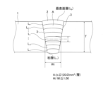
- FIG. 2 is a schematic cross-sectional view showing the shape of a weld metal of a welded joint according to the present invention.
- the welded joint according to the present invention is a butt-welded joint of steel plate having a plate thickness T (mm) of 50 mm or more, in which the weld metal is composed of multiple layers with one pass per layer, a first ratio [A/p] of the cross-sectional area A ( mm2 ) of the weld metal in a direction perpendicular to the weld line to the number of weld layers p (layers) is 120.0 mm2 /layer or less, and a second ratio [H/W] of the height H (mm) to the width W (mm) of each layer in the weld metal is 1.00 or less.
- the weld metal is constructed with one welding pass per layer of weld metal, making it possible to perform welding with high efficiency.
- a first ratio [A /p ], which is the cross-sectional area per layer when p weld layers are constructed from L1 (initial layer) to Lp (outermost layer) with respect to the cross-sectional area A (mm2) of the entire weld metal 2 in a direction perpendicular to the weld line 3 of the weld metal 2, is set to 120.0 mm2 /layer or less. That is, if the deposition area of the weld metal 2 is set to 120.0 mm2 or less per layer, the welding heat input is not excessive, the thermal effect on the base material, i.e., the steel plate 1, is sufficiently small, and a weld metal 2 with excellent low-temperature toughness can be obtained.
- the first ratio [A/p] is set to 60.0 mm2 /layer or less. More preferably, the first ratio [A/p] is set to 45.0 mm2 /layer or less.
- the second ratio [H/W] of the height H (mm) and width W (mm) of each layer in the weld metal 2 is 1.00 or less.
- the second ratio [H i /W i ] is 1.00 or less in any of the layers from the first layer (initial layer) to the p-th layer (outermost layer).
- the height H of the weld layer represents the distance between the upper and lower parts of each layer
- the width W represents the width (distance between fusion lines) of the weld metal 2 at the center line of the height H.
- the height H i and width W i of each layer are measured by cross-sectional macroscopic observation or the like, and the second ratio [H i /W i ] is obtained. If this second ratio [H/W] is greater than 1.00, hot cracking may occur more easily. This is because the solidification direction of the weld metal 2 coincides with the direction of tensile strain during cooling during the solidification process, and this causes the cracks to occur at the dendrite junctions. Therefore, the occurrence of hot cracks can be suppressed by controlling the maximum value of the second ratio [H/W] of each layer to 1.00 or less. Preferably, the second ratio [H/W] is 0.90 or less.
- the weld metal 2 of the welded joint according to the present invention is a weld metal 2 constructed by one-layer, one-pass multi-layer welding with a narrow groove.
- the narrow groove means that the groove angle is 20° or less, and the maximum groove width between the base materials, i.e., between the steel plates 1 butted against each other, is 50% or less of the plate thickness T.
- the maximum groove width between the base materials corresponds to the maximum groove width between the steel plates in this embodiment.
- the gap between the base materials is set to 6 mm or less and the groove angle is set to 20° or less, the occurrence of hot cracks can be suppressed.
- double-sided welding if the gap between the base materials is set to 10 mm or less and the groove angle is set to 20° or less, the occurrence of hot cracks can be suppressed.
- the gap between the base materials exceeds 6 mm, there is a possibility of poor fusion during welding of the first layer.
- the groove shape that can weld steel plates 1 of 50 mm or more efficiently and soundly is preferably a gap between the base materials of 6 mm or less and a groove angle of 20° or less, regardless of whether single-sided welding or double-sided welding is used. Furthermore, it is more preferable that the groove angle be 4 to 20°. In addition, in the case of double-sided welding, the groove area can be made smaller, so in this respect it is preferable to single-sided welding.
- the gap when the gap is 0 mm, i.e., when the base materials are in contact with each other, as will be clear from the examples described later, the width of the weld metal 2 becomes smaller relative to the height of the weld metal 2, and the weld bead shape approaches a pear shape. Therefore, welding strain is concentrated in the part where the melting point is lowered by impurities that segregate in the final solidification part of the weld metal 2. As a result, high-temperature cracks occur and poor fusion during welding is observed. Therefore, it is preferable that the gap is more than 0 mm. More preferably, the gap is 2 mm or more.
- the steel plate 1 which is the base material of the welded joint of the present invention will be described.
- the steel plate 1 may be a carbon steel or a low alloy steel.
- the chemical composition will be described, and "%" in the chemical composition described below means “mass %” unless otherwise specified.
- the basic chemical composition of the steel plate 1 of the welded joint according to the present invention is as follows.
- the steel sheet 1 has a chemical composition containing C: 0.04-0.14%, Si: 0.03-0.70%, Mn: 0.30-2.50%, P: 0.030% or less, S: 0.020% or less, Nb: 0.001-0.100%, Al: 0.001-0.100%, O: 0.0100% or less, and N: 0.0100% or less, with the balance being Fe and unavoidable impurities.
- C is an element that can most inexpensively improve the strength of the steel plate 1 and also contributes to strengthening the austenite grain boundaries. If the C content is less than 0.04%, the grain boundary strength of the austenite is The C content is reduced, and hot cracking of the slab occurs, so that manufacturability is significantly reduced. In addition, there is a possibility that the strength targeted by the present invention cannot be obtained. On the other hand, if the C content exceeds 0.14%, The weldability and toughness of the steel plate 1 may decrease. Therefore, the C content is preferably set to 0.04 to 0.14%. It is more preferable to set it to 12%.
- Si is an effective element for deoxidization, if the Si content is less than 0.03%, it may not be possible to obtain a sufficient effect. Therefore, the Si content is preferably 0.03 to 0.70%. The Si content is preferably 0.04 to 0.60%. It is more preferable to do so.
- Mn is an element that can improve the hardenability and strength of steel at low cost. To obtain this effect, it is preferable to contain 0.30% or more of Mn. If the Mn content exceeds 2.50%, the weldability of the steel plate 1 may decrease. Therefore, the Mn content is preferably set to 0.30 to 2.50%. It is more preferable to set it to 50 to 2.20%.
- P is an element that has a large effect of embrittling grain boundaries, and if contained in a large amount, it may reduce the toughness of the steel plate 1. Therefore, the P content is preferably 0.030% or less. Furthermore, the P content is more preferably 0.025% or less. On the other hand, since the lower the P content, the more preferable it is, the lower limit of the P content is not particularly limited and may be 0%. However, P is an element that is inevitably contained as an impurity in the steel sheet 1. If the P content is excessively low, it will lead to an increase in refining time and an increase in refining costs. Therefore, the P content is set to 0.001 % or more is preferable.
- the S content is preferably 0.020% or less. More preferably, it is 0.010% or less.
- S is an element that is inevitably contained in the steel sheet 1 as an impurity, and excessive S content If the amount is small, it will lead to an increase in refining time and refining costs, so the S content is preferably 0.0001% or more.
- Nb is an element that has the effect of suppressing recrystallization when strain is applied to the austenite structure through solid solution Nb and fine precipitated NbC, and also of raising the non-recrystallization temperature range to the higher temperature side.
- Nb is contained in an amount of 0.001% or more.
- the Nb content is preferably 0.001 to 0.100%.
- the Nb content is more preferably 0.005 to 0.075%.
- the Nb content is preferably 0.005 to 0.050%. It is particularly preferred to do so.
- Al is an element that is effective as a deoxidizer and also has the effect of forming nitrides to reduce the austenite grain size. To obtain this effect, the Al content is set to 0.001% or more. On the other hand, if the Al content exceeds 0.100%, the cleanliness of the steel material and the steel plate 1 may decrease, and as a result, the ductility and toughness of the steel plate 1 may decrease.
- the Al content is preferably 0.001 to 0.100%.
- the Al content is more preferably 0.005 to 0.080%.
- O 0.0100% or less
- the O content is preferably 0.0100% or less.
- the lower the O content the better. Therefore, the lower limit of the O content is
- O is an element that is inevitably contained as an impurity in the steel sheet 1, and if the O content is excessively low, it may increase the refining time or may cause problems such as the refining failure. Since this leads to an increase in costs, the O content is preferably set to 0.0005% or more.
- N 0.0100% or less
- the N content is preferably 0.0100% or less.
- the lower the N content the better, so the lower limit of the N content is particularly
- the N content is preferably 0.0005% or more.
- the steel plate 1 of the welded joint of the present invention has the above-mentioned basic composition, and thus the characteristics targeted by the present invention can be obtained.
- the steel plate 1 contains the following optional compositions as necessary in addition to the above-mentioned basic composition.
- the optional composition may be, for example, one or more selected from the group consisting of Cu: 2.000% or less, Ni: 2.500% or less, Cr: 1.500% or less, Mo: 1.000% or less, Ti: 0.100% or less, V: 0.300% or less, B: 0.0100% or less, W: 0.500% or less, Ca: 0.0200% or less, Mg: 0.0200% or less, and REM: 0.0500% or less.
- Cu is an element that can improve the strength of the steel plate 1 without significantly deteriorating the toughness of the steel plate 1.
- the Cu content exceeds 2.000%, a Cu-enriched layer formed immediately below the scale Hot cracking due to this may become a problem. Therefore, when Cu is contained, the Cu content is preferably 2.000% or less. More preferably, the Cu content is 0. .010 to 1.500%.
- Ni is an element that has the effect of increasing the hardenability and toughness of the steel plate 1. On the other hand, if the Ni content exceeds 2.500%, an increase in manufacturing costs may become a problem.
- the Ni content is preferably 2.500% or less, and more preferably 0.010 to 2.000%.
- Cr 1.500% or less
- Cr is an element that can improve the hardenability of the steel sheet 1, thereby improving the strength of the steel sheet 1.
- the Cr content is preferably 1.500% or less, and more preferably 0.010 to 1.200%.
- Mo is an element that can improve the hardenability of the steel sheet 1, thereby improving the strength of the steel sheet 1.
- the Mo content is preferably 1.000% or less, and more preferably, the Mo content is 0.010 to 0.800%.
- Ti 0.100% or less
- Ti is an element that has the effect of pinning the movement of crystal grain boundaries and suppressing grain growth by precipitating as TiN.
- the Ti content exceeds 0.100%, the structure of the steel sheet 1 The cleanliness may decrease, and as a result, the ductility and toughness may decrease. Therefore, when Ti is contained, the Ti content is preferably 0.100% or less. More preferably, The Ti content is 0.001 to 0.080%.
- V is an element that can improve the hardenability of the steel sheet 1 and can improve the strength of the steel sheet 1 by forming carbonitrides.
- the V content is preferably 0.300% or less. More preferably, the V content is 0.010 to 0.250%. .
- B is an element that has the effect of improving the hardenability of steel by adding a very small amount, thereby improving the strength of the steel plate 1.
- the B content is preferably 0.0100% or less. More preferably, the B content is 0.0001 to 0.0070%. .
- W 0.500% or less
- W is an element that can improve the hardenability of steel, thereby improving the strength of the steel plate 1.
- the W content is preferably 0.500% or less, and more preferably 0.010 to 0.400%.
- Ca 0.0200% or less
- Ca is an element that improves weldability by forming oxysulfides that are highly stable at high temperatures.
- the Ca content exceeds 0.0200%, the cleanliness of the steel sheet 1 decreases. The toughness may be impaired. Therefore, when Ca is contained, the Ca content is preferably 0.0200% or less. More preferably, the Ca content is 0.0001 to 0.0180%. It is.
- Mg is an element that forms oxysulfides that are highly stable at high temperatures, thereby improving the weldability of the steel sheet 1.
- the Mg content exceeds 0.0200%, the effect of adding Mg becomes saturated. Therefore, it is not possible to expect an effect commensurate with the content, which may be economically disadvantageous. Therefore, when Mg is contained, the Mg content is preferably 0.0200% or less. Preferably, the Mg content is 0.0001-0.0180%.
- REM 0.0500% or less
- REM rare earth metal
- the REM content is preferably 0.0500% or less. More preferably, the REM content is 0.0001 to 0.0450%.
- the steel plate 1 of the welded joint of the present invention has the above chemical composition, and the remainder is Fe and inevitable impurities.
- inevitable impurities include H, Zn, Re, Co, Sb, Bi, etc., and a total of 0.0100% or less is acceptable.
- elements other than these may be contained, and such embodiments are also included in the technical scope of the present invention.
- Ceq equivalent carbon content
- the chemical composition of the steel plate 1 satisfies the following conditions.
- the relationship between Ceq and plate thickness T (mm) is as follows: 0.0004T+0.25 ⁇ Ceq ⁇ 0.0004T+0.45...(1) It satisfies the above.
- each element symbol in the above formula (2) represents the content (mass%) of the corresponding element, and if the corresponding element is not contained, it is set to 0.
- the basic chemical composition of the weld metal 2 of the weld joint according to the present invention is as follows.
- the weld metal 2 has a chemical composition containing 0.050% or less, and N: 0.010% or less, with the balance being Fe and unavoidable impurities.
- each composition can be added (contained) to the weld metal 2 through either the steel plate 1, the flux, or the wire, which is the welding material.
- C is an element that has the effect of increasing the strength of the weld metal 2 by solid solution strengthening, and also contributes to strengthening the austenite grain boundaries.
- the C content is preferably set to 0.04 to 0.14%.
- the C content is more preferably set to 0.05 to 0.12%.
- Si:0.03-0.70% Silicon acts as a deoxidizer and has the effect of increasing the viscosity of the weld metal 2 and stably maintaining the shape of the weld bead. In order to obtain such an effect, the silicon content is set to 0.03%. However, if the Si content exceeds 0.70%, there is a possibility that the low-temperature toughness of the weld metal 2 may be reduced. In addition, Si segregates during solidification and forms liquid at the solidification cell interface. The Si content is preferably 0.03 to 0.70%. .60% is more preferable.
- Mn is an element that can improve the hardenability and strength of the weld metal 2 at low cost. To obtain this effect, it is preferable to contain 0.30% or more of Mn. If the content exceeds 2.50%, Mn segregation occurs during solidification, inducing hot cracking, which may reduce the weldability of the steel plate 1. Therefore, the Mn content is set to 0.30 to 1.5%. The Mn content is preferably 0.50 to 2.20%.
- P is an element that has a large effect of embrittling grain boundaries. If contained in a large amount, it reduces the low-temperature toughness of the weld metal 2 and may segregate at the interface during solidification, inducing high-temperature cracking. Therefore, the P content is preferably 0.030% or less, and more preferably 0.025% or less. On the other hand, since the lower the P content, the better, the lower limit of the P content is However, P is an element that is inevitably contained as an impurity in the weld metal 2, and if the P content is excessively low, the refining time increases. Therefore, the P content is preferably 0.001% or more.
- Nb is a carbide-forming element, and is an element that precipitates carbides and contributes to improving the strength of the weld metal 2.
- Nb precipitates carbides at the solidification cell interface of the weld metal 2, and reduces the occurrence of high-temperature cracks.
- the Nb content is preferably set to 0.001 to 0.100%.
- the Nb content is more preferably 0.075%.
- the Nb content is particularly preferably 0.005 to 0.050%.
- Al acts as a deoxidizer, increases the viscosity of the weld metal 2, and has an important effect of stably maintaining the weld bead shape.
- the Al content should be 0.001% or more.
- the Al content exceeds 0.100%, the cleanliness of the weld metal 2 decreases, and as a result, the ductility and toughness may decrease.
- the possibility of ductility-dip cracking, which is a type of hot cracking increases.
- the viscosity of the weld metal 2 becomes too high, which may prevent the weld bead from spreading and increase defects such as incomplete fusion.
- the Al content is preferably 0.001 to 0.100%, and more preferably 0.005 to 0.080%.
- Cu is an element that can improve the strength of the weld metal 2 without significantly deteriorating the toughness of the weld metal 2. In order to obtain this effect, the Cu content must be 0.001% or more. On the other hand, if the Cu content is more than 2.000%, it may segregate during solidification and induce hot cracking. It is preferable that the Cu content is 0.005 to 1.500%.
- Ni is an element that has the effect of increasing the hardenability and improving the toughness of the weld metal 2.
- the Ni content is preferably 0.001% or more.
- Ni is an expensive element, and if the Ni content exceeds 2.500%, it may be economically disadvantageous. Therefore, when Ni is contained, the Ni content is set to 2.500% or less.
- the Ni content is more preferably 0.010 to 2.000%.
- Cr 0.001 to 1.500%
- Cr is an element that can improve the hardenability of the weld metal 2, thereby improving the strength of the weld metal 2.
- the Cr content must be 0.001% or more.
- the Cr content exceeds 1.500%, the weldability may decrease.
- Cr carbides may be formed, which may lead to a decrease in low-temperature toughness. Therefore, it is preferable to use a Cr-containing steel.
- the Cr content is preferably 1.500% or less, and more preferably, the Cr content is 0.010 to 1.200%.
- Mo is an element that can improve the hardenability of the weld metal 2, thereby improving the strength of the weld metal 2. In order to obtain this effect, the Mo content must be 0.001% or more. On the other hand, if the Mo content exceeds 1.000%, the weldability may decrease. Therefore, when Mo is contained, the Mo content is preferably 1.000% or less. More preferably, the Mo content is 0.010 to 0.800%.
- Ti 0.001 to 0.100%
- Ti is an element that can precipitate as fine carbonitrides in the weld metal 2 and improve the strength of the weld metal 2. To obtain this effect, the Ti content is set to 0.001% or more. On the other hand, if the Ti content exceeds 0.100%, the cleanliness of the structure of the weld metal 2 decreases, and as a result, the ductility and toughness may decrease. If Ti is added, the Ti content is preferably 0.100% or less, and more preferably 0.005 to 0.080%.
- V is an element that can improve the hardenability of the weld metal 2 and can improve the strength of the weld metal 2 by forming carbonitrides. To obtain this effect, the V content is set to 0.001%. On the other hand, if the V content exceeds 0.300%, the weldability may decrease. Therefore, when V is contained, the V content is set to 0.300% or less. The V content is more preferably 0.005 to 0.250%.
- B is an element that has the effect of improving the hardenability by adding a very small amount, thereby improving the strength of the weld metal 2.
- the B content is set to 0.001% or more.
- the B content is preferably 0.020% or less. It is preferable that the B content is 0.005 to 0.018%.
- O 0.050% or less
- the O content is preferably 0.050% or less.
- O is an element that is inevitably contained in the weld metal 2 as an impurity, and if the O content is excessively low, the refining time increases. Therefore, the O content is preferably 0.0005% or more.
- N 0.010% or less
- the N content is preferably 0.010% or less.
- the content of N may be more than 0% industrially. Incidentally, if the N content is excessively low, it will lead to an increase in the refining time and the refining cost, so the N content is preferably 0.0005% or more.
- the weld metal 2 of the present invention can obtain the characteristics targeted by the present invention by using the basic composition described above. However, for the purpose of further improving the strength and weldability, i.e., the toughness of the welded portion and the welding workability, it is preferable that the weld metal 2 contains the following optional compositions as necessary in addition to the basic composition described above.
- W 0.500% or less
- Ca 0.0200% or less
- Mg 0.0200% or less
- REM 0.0500% or less.
- W is an element that can improve the hardenability of the weld metal 2, thereby improving the strength of the weld metal 2.
- the W content is preferably 0.500% or less. More preferably, the W content is 0.010 to 0.400%.
- Ca 0.0200% or less
- Ca is an element that forms oxysulfides that are highly stable at high temperatures, thereby improving the weldability of the weld metal 2.
- the Ca content exceeds 0.0200%, the cleanliness decreases. As a result, the toughness of the weld metal 2 may be impaired. Therefore, when Ca is contained, the Ca content is preferably set to 0.0200% or less. More preferably, the Ca content is set to 0. 0.0001 to 0.0180%.
- Mg is an element that forms oxysulfides that are highly stable at high temperatures, thereby improving the weldability of the weld metal 2.
- Mg content exceeds 0.0200%, the effect of adding Mg is reduced.
- the effect of Mg is saturated and no effect commensurate with the content can be expected, which may be economically disadvantageous. Therefore, when Mg is contained, the Mg content is preferably 0.0200% or less. More preferably, the Mg content is 0.0001 to 0.0180%.
- REM 0.0500% or less
- REM rare earth metal
- REM is an element that forms oxysulfides that are highly stable at high temperatures, thereby improving the weldability of the weld metal 2.
- the REM content exceeds 0.0500%, The effect of adding REM becomes saturated and the effect commensurate with the content cannot be expected, which may be economically disadvantageous. Therefore, when REM is contained, the REM content should be 0.0500% or less. It is preferable that the REM content is 0.0001 to 0.0450%.
- the chemical composition other than the above-mentioned chemical composition that is, the balance
- Fe iron
- inevitable impurities refer to components that are mixed into the weld metal 2 from the welding wire, flux, steel sheet 1, surrounding atmosphere, etc. during the welding process, and are not intentionally contained in the weld metal 2.
- inevitable impurities include H, Zn, Re, Co, Sb, Bi, etc., and a total of 0.0100% or less is acceptable.
- elements other than these may be contained as long as the above-mentioned basic composition and optional composition are satisfied, and such embodiments are also included in the technical scope of the present invention.
- the dislocation density ⁇ (m -2 ) at a position 1 mm below the surface of the steel plate 1 is preferably 4.0 ⁇ 10 14 m -2 or less.
- the dislocation density ⁇ (m -2 ) means the length of the dislocation line per unit volume present in the crystal of the metal.
- the position 1 mm below the surface of the steel plate 1 is specified from the viewpoint of the bending workability of the steel plate 1.
- the bending workability of the steel plate 1 is determined by the ductility of the surface layer structure of the steel plate 1.
- the dislocation density at a position 1 mm below the surface of the steel plate 1 is set to 4.0 ⁇ 10 14 m -2 or less. Note that, since dislocations are usually unavoidable in the steel structure, it is very costly to make the dislocation density less than 1.0 ⁇ 10 11 m -2 . Therefore, the dislocation density is preferably 1.0 ⁇ 10 11 m ⁇ 2 or more, and more preferably 3.0 ⁇ 10 14 m ⁇ 2 or less.
- the average grain size at a position 1 mm below the surface of the steel plate 1 is 15.0 ⁇ m or less, and the average grain size at the center position of the thickness of the steel plate 1 is 20.0 ⁇ m or less.
- the average grain size means the average grain size of all grains at a position 1 mm below the surface of the steel plate 1 and at the center of the thickness of the steel plate 1, when the region surrounded by the boundary with a crystal orientation difference of 15° or more is regarded as a grain.
- the average grain size can be measured by the method described in the examples below. The finer the grain size of the surface structure of the steel plate 1, the more the toughness of the surface of the steel plate 1 is improved. To obtain this effect, the average grain size at a position 1 mm below the surface of the steel plate 1 must be 15.0 ⁇ m or less. Therefore, the average grain size at a position 1 mm below the surface of the steel plate 1 must be 15.0 ⁇ m or less.
- the average grain size is 13.0 ⁇ m or less. Furthermore, the finer the grain size of the steel structure at the center of the thickness of the steel plate 1, the more the toughness of the steel plate 1 at the center of the thickness of the steel plate 1 is improved. To obtain this effect, the average grain size at the center of the thickness of the steel plate 1 must be 20.0 ⁇ m or less. Therefore, the average crystal grain size at the center of the thickness of the steel plate 1 is set to 20.0 ⁇ m or less. More preferably, the average crystal grain size is 15.0 ⁇ m or less.
- “1 mm below the surface of the steel plate” means a depth position of 1 mm from the surface of the steel plate 1 in the thickness direction.
- Center of the thickness means a position at 1/2 the thickness of the steel plate 1.
- the steel sheet 1 of the present invention is obtained by heating, hot rolling, and cooling a slab (steel material) having the above-mentioned composition. After the cooling, the steel sheet 1 of the present invention can be further subjected to an optional tempering. Various preferable conditions in the method for manufacturing the steel sheet 1 of the present invention will be described below. However, the method for manufacturing the steel sheet 1 of the present invention is not limited to the manufacturing method described below, and it is sufficient if it has the characteristics described below.
- the temperature indicated in “°C” refers to the surface temperature of the slab and steel plate 1 unless otherwise specified.
- the surface temperature can be measured, for example, with a radiation thermometer.
- the method for producing the slab is not particularly limited, and any of the known methods for producing the slab, such as converters, electric furnaces, and vacuum melting furnaces, are suitable.
- the slab is produced to the desired dimensions, for example, by a continuous casting method.
- the molten steel may further be subjected to secondary refining, such as ladle refining.
- the manufactured slab it is preferable to heat the manufactured slab to a temperature of 1000 to 1200°C. If the heating temperature of the slab is less than 1000°C, the coarse NbC precipitated inside the slab during slab casting will not redissolve and will remain. As a result, the effect of lowering the non-recrystallization temperature range due to the dissolved Nb and the fine NbC reprecipitated during hot rolling will not be obtained. As a result, the effect of refining the crystal grains by controlled rolling will be reduced, and the toughness of the steel sheet 1, which is the final product, will decrease.
- the heating temperature of the slab exceeds 1200°C, the grain size at the start of hot rolling will become coarse due to the grain growth of austenite, and therefore the grain size of the final structure after hot rolling will also become coarse, and the toughness of the steel sheet 1 will decrease. Therefore, it is preferable to heat the slab to a temperature of 1000 to 1200°C. More preferably, the heating temperature of the slab is 1030°C or higher, and even more preferably, 1170°C or lower.
- the heated slab is then preferably hot rolled.
- the dislocation density and average grain size 1 mm below the surface of the steel sheet 1, and the average grain size at the center of the thickness of the steel sheet 1 are important. In order to obtain various properties, it is preferable to roll the slab under the following hot rolling conditions.
- the temperature range 1 mm below the surface of the steel plate 1 or the temperature range at the center of the thickness of the steel plate 1 that exceeds (8250 [Nb] + 770°C) is referred to as the recrystallization temperature range.
- the temperature range 1 mm below the surface of the steel plate 1 or the temperature range at the center of the thickness of the steel plate 1 that is between (8250 [Nb] + 770°C) and Ar3 temperature is referred to as the non-recrystallization temperature range.
- the temperature at the center of the thickness of the steel plate 1 can be obtained, for example, by drilling a straight hole 5 mm in diameter to the center of the thickness of the steel plate 1 and measuring with a thermocouple there, or by calculating the temperature distribution in the cross section of the steel plate 1 by heat transfer analysis and correcting the result by the surface temperature of the steel plate 1.
- [Nb] represents the content (mass%) of the element.
- the temperature of the steel sheet 1 at a position 1 mm below the surface of the steel sheet 1 is temporarily cooled to Ar3 temperature or lower, and then reheated to exceed Ac3 temperature.
- the steel sheet 1 is subjected to reduction with a reduction rate of 25% or more.
- the steel sheet 1 is subjected to reduction with a total reduction rate of 15% or less.
- the surface layer of the steel sheet 1 is once cooled to the Ar3 temperature or lower, thereby transforming the austenite into a low-temperature structure such as ferrite.
- the surface layer of the steel sheet 1 is then heated to the Ac3 temperature or higher by reheating, thereby retransforming the surface layer into an austenite structure, and the surface layer of the steel sheet 1 becomes fine austenite.
- the cooling of the steel sheet 1 may be performed by water cooling, air cooling, or the like, and any method may be used as long as the temperature can be controlled to a predetermined level.
- cooling to Ar3 temperature or lower is performed by water cooling, and the residence time during which the temperature at a position 1 mm below the surface of the steel sheet 1 is Ar3 temperature or lower is preferably 5 seconds or more, and preferably 300 seconds or less.
- Reheating after cooling is performed by holding the steel sheet 1 in the atmosphere, and the holding time is preferably 30 seconds or more, and preferably 600 seconds or less.
- a rolling reduction of 25% or more is applied to the steel sheet 1 in the temperature range of (8250 [Nb] + 770 ° C.) to Ar 3 temperature, where the surface layer of the steel sheet 1 is in the non-recrystallization temperature range, to introduce processing strain into the austenite in the surface layer of the steel sheet 1.
- This acts as a transformation nucleus during final cooling, resulting in a fine structure with good toughness.
- the rolling reduction in the above-mentioned temperature range is 30% or more. From the viewpoint of rolling efficiency, the rolling reduction in this temperature range is preferably 80% or less, and even more preferably 70% or less.
- the steel plate 1 is subjected to rolling so that the total rolling reduction is 25% or more.
- the total reduction rate for steel plate 1 it is preferable to set the total reduction rate for steel plate 1 to 25% or more when the temperature at the center of the thickness of steel plate 1 is in a temperature range below (8250 [Nb] + 770°C). More preferably, the total reduction rate for steel plate 1 is 35% or more. From the viewpoint of rolling efficiency, it is preferable that the total reduction rate for steel plate 1 in this temperature range be 70% or less, and even more preferably 67% or less.
- the temperature at the center of the thickness of the steel plate 1 is lower than the Ar 3 temperature, processing strain is introduced into the generated ferrite, and the toughness of the steel plate 1 decreases. Therefore, it is preferable that the temperature at the center of the thickness of the steel plate 1 is equal to or higher than the Ar 3 temperature.
- the temperature ranges may overlap within the rolling conditions described above for the two types of rolling, "rolling on the steel plate surface” and “rolling on the plate thickness center position.”
- the reduction amounts in the overlapping temperature ranges are added up as the reduction amounts for the "steel plate surface” and the "plate thickness center position,” and this added-up reduction amount should be within the range of each rolling condition.
- r0 is the thickness at which the first rolling is started
- r1 is the thickness after the last rolling.
- the Ar 3 temperature and Ac 3 temperature can be obtained by a Formaster test or the like.
- the center of the thickness of the steel plate 1 can have a structure with small crystal grain size and excellent toughness.
- the steel sheet 1 produced by the above-mentioned hot rolling of the slab is cooled. Specifically, the steel sheet 1 is cooled so that the average cooling rate of the steel sheet 1 when the temperature at the center position of the thickness of the steel sheet 1 is in the temperature range of 700 to 550°C, assuming that the thickness of the steel sheet 1 is t [mm], is 2500 x t -1.7 °C/sec or more.
- the cooling method include water cooling in which a large amount of water is sprayed from a nozzle. In the present invention, it is preferable to perform a cooling operation (treatment) on both sides of the steel sheet 1 so that both sides of the steel sheet 1 are cooled under the same conditions.
- the average cooling rate of the steel plate 1 when the temperature at the center of the thickness of the steel plate 1 after hot rolling of the slab is between 700 and 550°C is less than 2500 x t -1.7 ° C/sec, the cooling rate in the temperature range where transformation from austenite to a low-temperature transformation structure occurs will be insufficient, and as a result, the required strength of the steel plate 1 intended in the present invention may not be obtained. In addition, coarse ferrite may be generated, which may reduce the toughness of the steel plate 1. Therefore, it is preferable that the average cooling rate of the steel plate 1 when the temperature at the center of the thickness of the steel plate 1 is in the temperature range of 700 to 550°C is 2500 x t -1.7 ° C/sec or more.
- the steel plate 1 after cooling the steel plate 1, the steel plate 1 can be tempered as necessary in order to further improve the strength and toughness of the steel plate 1.
- the steel plate 1 is tempered at a tempering temperature of 650°C or less after cooling. If the tempering temperature is higher than 650°C, significant softening of the steel plate 1 may occur, making it impossible to ensure the necessary strength. For this reason, it is preferable to set the tempering temperature to 650°C or less.
- the lower limit of the tempering temperature is not particularly limited, but it is preferable to set it to 200°C or more.
- the tempering time can be adjusted as appropriate.
- the tempering temperature here refers to the temperature of the surface of the steel plate 1.
- the welded metal 2 having the above-mentioned chemical composition and produced in accordance with the JIS Z 3111:2005 standard has a room temperature yield strength (0.2% proof stress) of 325 MPa or more and a tensile strength of 520 MPa or more in a tensile test. It is also preferable that the room temperature tensile strength of the welded joint is 520 MPa or more.
- the absorbed energy ( v E -40 ) of a V-notch Charpy impact test at a test temperature of -40°C for the welded metal 2 and heat-affected zone of a welded joint produced in accordance with the JIS Z 3128:2017 standard is 30 J or more. This is because if it is less than 30 J, the toughness of a structure having this welded joint is reduced and destruction may occur more easily.
- the groove-processed steel plates 1 are welded together, specifically, one pass per layer is used to form a multi-layer weld metal 2, preferably three or more layers, to form a weld joint. If the steel plates 1 are welded together so as to form one or two layers of weld metal 2, the heat generated during welding may not spread uniformly within the groove, potentially inducing welding defects.
- the welding material used when welding the steel plates 1 together is not particularly limited as long as it can form a weld metal 2 with the desired characteristics, and there are no particular limitations on the type of welding wire, filler rod, welding flux, etc.
- the welding method may be submerged arc welding or gas metal arc welding (also called gas shielded arc welding).
- submerged arc welding also called gas shielded arc welding.
- it is preferable to use submerged arc welding because it allows for highly efficient welding.
- multi-electrode submerged arc welding which is a more efficient welding method.
- it is a welding method using a submerged arc welder having two electrodes. In this two-electrode submerged arc welding, the leading first electrode generates an arc from one wire passed through one torch, and the trailing second electrode generates an arc from two wires passed through one torch to perform submerged arc welding.
- the arc generated from the tip of the wire of the first electrode melts the bottom of the groove, thereby suppressing the occurrence of poor fusion.
- the mutual arcs accelerate the melting of the wires, and the amount of deposited metal can be increased. This makes it possible to perform more efficient welding.
- the welding conditions when performing two-electrode submerged arc welding are preferably such that the current value of the first electrode is 600-1200 A and the voltage value is 24-45 V, and the current value of the second electrode is 450-1200 A and the voltage value is 30-48 V.
- the welding speed is 50-130 cm/min and the heat input is 10-100 kJ/cm.
- the welding wire and welding flux used in two-electrode submerged arc welding are adjusted in composition to take into account dilution of the base material so that the composition of the weld metal 2 is as described above. Note that as long as the composition of the weld metal 2 is within the aforementioned range of components, there are no particular limitations on the type of welding wire or welding flux.
- Welding wire can be solid wire or flux-cored wire, which contains flux for wire inside the wire. Either type of welding wire can be used in the present invention. When using flux-cored wire, it is manufactured so that the total value of the composition of the steel sheath, metal powder, and flux powder for wire used is the composition of the target welding material.
- the welding flux may be a molten flux or a sintered flux. Either type of welding flux may be used in the present invention.
- the slab containing the above-mentioned components was subjected to the steps of heating, hot rolling, and cooling in order to obtain a steel plate with a thickness T (mm) shown in Table 2.
- the rolling start temperature in the hot rolling process was in the range of 990 to 1140°C at the surface layer of the steel plate, and the rolling finish temperature was in the range of 670 to 830°C at the surface layer of the steel plate.
- the above steel plate temperatures were measured by measuring the surface temperature with an emissivity thermometer, and the temperature at the center of the plate thickness was measured by drilling a straight hole of 5 mm ⁇ to the center of the plate thickness of the steel plate and attaching a thermocouple to the hole.
- Table 2 shows whether or not Ceq, which is an index of the hardenability of steel, satisfies the above-mentioned formula (1). If Ceq satisfies formula (1), a " ⁇ " is entered in the column for determining formula (1) in Table 2, and if it does not satisfy formula (1), a " ⁇ " is entered in the column for determining formula (1) in Table 2.
- molten steel with the chemical composition (welding material composition) shown in Table 3 was melted in a vacuum melting furnace and cast to obtain a steel ingot.
- the resulting steel ingot was heated to 1200°C, hot rolled, and then cold rolled to produce 4.0 mm ⁇ and 2.4 mm ⁇ solid wire for submerged arc welding, and 1.2 mm ⁇ solid wire for gas metal arc welding.
- a flux cored wire was separately prepared, in which a steel sheath and metal powder and flux powder were enclosed within the steel sheath.
- a thin steel plate with a thickness of 0.5 mm and a composition of 0.1% C-0.2% Si-0.5% Mn-balance Fe was used as the steel sheath material, and cold bending was performed in the width direction to form a U-shape.
- Metal powder and flux powder with the composition adjusted to the chemical composition shown in Table 3 were then enclosed within the obtained steel sheath. This was cold drawn to produce flux cored wire for welding (diameters: 1.2, 2.4, 4.0 mm).
- the chemical composition shown in Table 3 is the total value of the steel sheath, metal powder, and flux powder.
- the cross-sectional area A (mm2) of the entire weld metal in the direction perpendicular to the weld line of the weld metal was measured, and the first ratio [A/p] of the cross-sectional area A of the weld metal and the number of weld layers p, obtained by dividing it by the number of weld layers p (layers), was recorded.
- the distance between the top and bottom of each layer of weld metal was measured to determine the height H (mm) of each layer of weld metal, and the width of the weld metal at the center line of each height H, i.e., the distance between the fusion lines, was measured to determine the width W (mm) of the weld metal.
- the second ratios [H/W] were calculated for each layer, and the maximum and minimum values of the second ratios [H/W] for the entire weld metal were recorded.
- the surface layer and the center of the thickness of the steel plate of the present invention were mainly composed of bainite and pseudo-polygonal ferrite.
- test specimens were taken perpendicular to the weld axis so that the weld axis was in the center of the length of the parallel part of the test specimen, and the thickness of the test specimen was the full thickness of the welded joint, making it a Type 1A test specimen.
- the target values in the present invention are a room temperature yield strength (0.2% proof stress) of the weld metal of 325 MPa or more, a tensile strength of the weld metal of 520 MPa or more, and a room temperature tensile strength of the welded joint of 520 MPa or more.
- the absorbed energy ( vE -40 ) in a Charpy impact test at a test temperature of -40°C for the weld metal and heat-affected zone is set to 30 J or more.
- the weld joints were sound and free from weld defects such as hot cracking and incomplete fusion.
- the room temperature yield strength (0.2% proof stress) of the weld metal was 325 MPa or more
- the tensile strength was 520 MPa or more
- the room temperature tensile strength of the weld joint was 520 MPa or more.
- the absorbed energy ( v E -40 ) of the weld metal and heat-affected zone in a Charpy impact test at a test temperature of -40°C was 30 J or more, and the weld joints had weld metal that had both high strength and excellent low-temperature toughness.
- any of the mechanical properties such as the room temperature yield strength (0.2% proof stress) and tensile strength of the weld metal, the room temperature tensile strength of the welded joint, and the absorbed energy ( vE -40 ) in a Charpy impact test at a test temperature of -40°C for the weld metal and heat-affected zone, were at a slightly low level.
Landscapes
- Chemical & Material Sciences (AREA)
- Engineering & Computer Science (AREA)
- Mechanical Engineering (AREA)
- Materials Engineering (AREA)
- Metallurgy (AREA)
- Organic Chemistry (AREA)
- Physics & Mathematics (AREA)
- Thermal Sciences (AREA)
- Crystallography & Structural Chemistry (AREA)
- Plasma & Fusion (AREA)
- Arc Welding In General (AREA)
Priority Applications (4)
| Application Number | Priority Date | Filing Date | Title |
|---|---|---|---|
| CN202480009911.2A CN120677025A (zh) | 2023-02-06 | 2024-02-01 | 钢板的焊接接头及其制造方法 |
| EP24753234.4A EP4628239A1 (en) | 2023-02-06 | 2024-02-01 | Steel plate welded joint and method for manufacturing same |
| JP2024532695A JP7802175B2 (ja) | 2023-02-06 | 2024-02-01 | 鋼板の溶接継手およびその製造方法 |
| KR1020257025027A KR20250132509A (ko) | 2023-02-06 | 2024-02-01 | 강판의 용접 이음매 및 그 제조 방법 |
Applications Claiming Priority (2)
| Application Number | Priority Date | Filing Date | Title |
|---|---|---|---|
| JP2023-015802 | 2023-02-06 | ||
| JP2023015802 | 2023-02-06 |
Publications (1)
| Publication Number | Publication Date |
|---|---|
| WO2024166791A1 true WO2024166791A1 (ja) | 2024-08-15 |
Family
ID=92262513
Family Applications (1)
| Application Number | Title | Priority Date | Filing Date |
|---|---|---|---|
| PCT/JP2024/003364 Ceased WO2024166791A1 (ja) | 2023-02-06 | 2024-02-01 | 鋼板の溶接継手およびその製造方法 |
Country Status (5)
| Country | Link |
|---|---|
| EP (1) | EP4628239A1 (https=) |
| JP (1) | JP7802175B2 (https=) |
| KR (1) | KR20250132509A (https=) |
| CN (1) | CN120677025A (https=) |
| WO (1) | WO2024166791A1 (https=) |
Citations (9)
| Publication number | Priority date | Publication date | Assignee | Title |
|---|---|---|---|---|
| JPS5584280A (en) * | 1978-12-19 | 1980-06-25 | Nippon Steel Corp | Narrow groove submerged arc welding method |
| JPS5584278A (en) * | 1978-12-19 | 1980-06-25 | Nippon Steel Corp | Shallow penetration submerged arc welding method |
| JPS55120488A (en) * | 1979-03-09 | 1980-09-16 | Nippon Steel Corp | Narrow gap submerged arc welding method |
| JPS59212176A (ja) * | 1983-05-16 | 1984-12-01 | Kawasaki Steel Corp | 潜弧溶接方法 |
| JP2006212676A (ja) | 2005-02-04 | 2006-08-17 | Nippon Steel & Sumikin Welding Co Ltd | 2電極大入熱サブマージアーク溶接方法 |
| JP4673710B2 (ja) | 2005-09-22 | 2011-04-20 | 新日本製鐵株式会社 | 溶接金属の靱性に優れた2電極片面1パス大入熱サブマージアーク溶接方法 |
| WO2013073565A1 (ja) | 2011-11-15 | 2013-05-23 | 新日鐵住金株式会社 | 厚鋼板の高能率溶接方法 |
| WO2021054344A1 (ja) * | 2019-09-20 | 2021-03-25 | Jfeスチール株式会社 | 厚鋼板および厚鋼板の製造方法 |
| JP2021126696A (ja) | 2020-02-17 | 2021-09-02 | 日鉄溶接工業株式会社 | 狭開先サブマージアーク溶接方法 |
-
2024
- 2024-02-01 EP EP24753234.4A patent/EP4628239A1/en active Pending
- 2024-02-01 CN CN202480009911.2A patent/CN120677025A/zh active Pending
- 2024-02-01 JP JP2024532695A patent/JP7802175B2/ja active Active
- 2024-02-01 KR KR1020257025027A patent/KR20250132509A/ko active Pending
- 2024-02-01 WO PCT/JP2024/003364 patent/WO2024166791A1/ja not_active Ceased
Patent Citations (9)
| Publication number | Priority date | Publication date | Assignee | Title |
|---|---|---|---|---|
| JPS5584280A (en) * | 1978-12-19 | 1980-06-25 | Nippon Steel Corp | Narrow groove submerged arc welding method |
| JPS5584278A (en) * | 1978-12-19 | 1980-06-25 | Nippon Steel Corp | Shallow penetration submerged arc welding method |
| JPS55120488A (en) * | 1979-03-09 | 1980-09-16 | Nippon Steel Corp | Narrow gap submerged arc welding method |
| JPS59212176A (ja) * | 1983-05-16 | 1984-12-01 | Kawasaki Steel Corp | 潜弧溶接方法 |
| JP2006212676A (ja) | 2005-02-04 | 2006-08-17 | Nippon Steel & Sumikin Welding Co Ltd | 2電極大入熱サブマージアーク溶接方法 |
| JP4673710B2 (ja) | 2005-09-22 | 2011-04-20 | 新日本製鐵株式会社 | 溶接金属の靱性に優れた2電極片面1パス大入熱サブマージアーク溶接方法 |
| WO2013073565A1 (ja) | 2011-11-15 | 2013-05-23 | 新日鐵住金株式会社 | 厚鋼板の高能率溶接方法 |
| WO2021054344A1 (ja) * | 2019-09-20 | 2021-03-25 | Jfeスチール株式会社 | 厚鋼板および厚鋼板の製造方法 |
| JP2021126696A (ja) | 2020-02-17 | 2021-09-02 | 日鉄溶接工業株式会社 | 狭開先サブマージアーク溶接方法 |
Non-Patent Citations (1)
| Title |
|---|
| See also references of EP4628239A1 |
Also Published As
| Publication number | Publication date |
|---|---|
| TW202432292A (zh) | 2024-08-16 |
| EP4628239A1 (en) | 2025-10-08 |
| CN120677025A (zh) | 2025-09-19 |
| JP7802175B2 (ja) | 2026-01-19 |
| KR20250132509A (ko) | 2025-09-04 |
| JPWO2024166791A1 (https=) | 2024-08-15 |
Similar Documents
| Publication | Publication Date | Title |
|---|---|---|
| CA2860605C (en) | Abrasion resistant welded steel pipe and method of producing the same | |
| US20110250471A1 (en) | Ultrahigh strength welded joint and ultrahigh strength welded steel pipe excellent in cold cracking resistance of weld metal, and methods for producing the same | |
| JP4811166B2 (ja) | 引張強度800MPaを超える超高強度溶接鋼管の製造方法 | |
| JP4848966B2 (ja) | 厚肉高張力鋼板およびその製造方法 | |
| JP2008248315A (ja) | 母材および溶接部靱性に優れた超高強度高変形能溶接鋼管の製造方法 | |
| US20150361664A1 (en) | H-section steel and method of producing the same | |
| JP5413537B2 (ja) | 変形性能及び低温靭性に優れた高強度鋼板及び高強度鋼管並びにこれらの製造方法 | |
| CN106011622A (zh) | 一种超高强度高变形性能的焊接钢管的制造方法 | |
| JP2007262441A (ja) | 原油タンク用鋼およびその製造方法 | |
| JP6720825B2 (ja) | 熱加工制御型590MPa級H形鋼 | |
| JP7802175B2 (ja) | 鋼板の溶接継手およびその製造方法 | |
| JP7802174B2 (ja) | 鋼板の溶接継手およびその製造方法 | |
| JP7558480B1 (ja) | 鋼板のガスシールドアーク溶接による溶接継手の製造方法 | |
| JP7558479B1 (ja) | 鋼板のガスシールドアーク溶接による溶接継手の製造方法 | |
| TWI915734B (zh) | 鋼板的焊接接頭及其製造方法 | |
| TWI898511B (zh) | 鋼板的採用氣體保護電弧焊接的焊接接頭的製造方法 | |
| TWI916755B (zh) | 鋼板的焊接接頭及其製造方法 | |
| TWI892547B (zh) | 鋼板的採用氣體保護電弧焊接的焊接接頭的製造方法 | |
| JP7816647B2 (ja) | Tig溶接方法及びtig溶接継手 | |
| JP2026001848A (ja) | 鋼板およびその製造方法 | |
| WO2025023221A1 (ja) | 溶接継手 | |
| JPH10273751A (ja) | 高張力鋼および溶接高張力鋼管 | |
| KR20250040026A (ko) | 레이저 용접 방법 및 레이저 용접 조인트 |
Legal Events
| Date | Code | Title | Description |
|---|---|---|---|
| WWE | Wipo information: entry into national phase |
Ref document number: 2024532695 Country of ref document: JP |
|
| 121 | Ep: the epo has been informed by wipo that ep was designated in this application |
Ref document number: 24753234 Country of ref document: EP Kind code of ref document: A1 |
|
| WWE | Wipo information: entry into national phase |
Ref document number: 2024753234 Country of ref document: EP |
|
| ENP | Entry into the national phase |
Ref document number: 2024753234 Country of ref document: EP Effective date: 20250630 |
|
| ENP | Entry into the national phase |
Ref document number: 1020257025027 Country of ref document: KR Free format text: ST27 STATUS EVENT CODE: A-0-1-A10-A15-NAP-PA0105 (AS PROVIDED BY THE NATIONAL OFFICE) |
|
| WWE | Wipo information: entry into national phase |
Ref document number: 1020257025027 Country of ref document: KR |
|
| WWE | Wipo information: entry into national phase |
Ref document number: 2501004948 Country of ref document: TH |
|
| WWE | Wipo information: entry into national phase |
Ref document number: 202480009911.2 Country of ref document: CN |
|
| WWE | Wipo information: entry into national phase |
Ref document number: 11202503926P Country of ref document: SG |
|
| WWP | Wipo information: published in national office |
Ref document number: 11202503926P Country of ref document: SG |
|
| NENP | Non-entry into the national phase |
Ref country code: DE |
|
| WWP | Wipo information: published in national office |
Ref document number: 202480009911.2 Country of ref document: CN |
|
| WWP | Wipo information: published in national office |
Ref document number: 2024753234 Country of ref document: EP |