WO2024166605A1 - ファスニングパーツ、スライドファスナー、及びファスニングパーツ付き布地の製造方法 - Google Patents
ファスニングパーツ、スライドファスナー、及びファスニングパーツ付き布地の製造方法 Download PDFInfo
- Publication number
- WO2024166605A1 WO2024166605A1 PCT/JP2024/000675 JP2024000675W WO2024166605A1 WO 2024166605 A1 WO2024166605 A1 WO 2024166605A1 JP 2024000675 W JP2024000675 W JP 2024000675W WO 2024166605 A1 WO2024166605 A1 WO 2024166605A1
- Authority
- WO
- WIPO (PCT)
- Prior art keywords
- fastening part
- fastening
- fastening parts
- fabric
- rows
- Prior art date
- Legal status (The legal status is an assumption and is not a legal conclusion. Google has not performed a legal analysis and makes no representation as to the accuracy of the status listed.)
- Ceased
Links
Images







Classifications
-
- A—HUMAN NECESSITIES
- A44—HABERDASHERY; JEWELLERY
- A44B—BUTTONS, PINS, BUCKLES, SLIDE FASTENERS, OR THE LIKE
- A44B18/00—Fasteners of the touch-and-close type; Making such fasteners
-
- A—HUMAN NECESSITIES
- A44—HABERDASHERY; JEWELLERY
- A44B—BUTTONS, PINS, BUCKLES, SLIDE FASTENERS, OR THE LIKE
- A44B19/00—Slide fasteners
- A44B19/02—Slide fasteners with a series of separate interlocking members secured to each stringer tape
- A44B19/04—Stringers arranged edge-to-edge when fastened, e.g. abutting stringers
-
- A—HUMAN NECESSITIES
- A44—HABERDASHERY; JEWELLERY
- A44B—BUTTONS, PINS, BUCKLES, SLIDE FASTENERS, OR THE LIKE
- A44B19/00—Slide fasteners
- A44B19/42—Making by processes not fully provided for in one other class, e.g. B21D53/50, B21F45/18, B22D17/16, B29D5/00
-
- A—HUMAN NECESSITIES
- A44—HABERDASHERY; JEWELLERY
- A44B—BUTTONS, PINS, BUCKLES, SLIDE FASTENERS, OR THE LIKE
- A44B99/00—Subject matter not provided for in other groups of this subclass
Definitions
- This disclosure relates to a method for manufacturing fastening parts, slide fasteners, and fabrics with fastening parts.
- Patent Document 1 discloses that a tape-free stringer is sewn directly to the fabric of a garment for various purposes, such as reducing the weight of a slide fastener, reducing costs, or achieving a good-looking installation.
- the stringer has a fastener element made of monofilament and an element fixing member inserted between the upper and lower legs of the fastener element, and the fastener element and the element fixing member are sewn together (see Figure 3 in the same document).
- Patent Document 2 discloses a novel fastening system.
- the fastening system has a first and a second fastening device.
- Each fastening device includes a fastening portion and a tape portion connected thereto.
- a clearance groove is formed in the fastening portion (see Figure 2 in the same document).
- Patent document 3 discloses that fastener elements are attached to both ends of a cloth tape, and the cloth tape is bent and connected to an article at its center (see Figure 2 in the document).
- Patent document 4 discloses a slide fastener in which male and female strips fit together tightly.
- Fastener elements made of monofilament such as those in Patent Document 1
- the inventors of the present application have discovered a new challenge: providing fastening parts that can be attached to articles and are suitable for mass production.
- a fastening part is a long fastening part that can be attached directly to an edge of an article or via an intervening object.
- the fastening part includes an attachment surface provided on one side in a thickness direction perpendicular to the longitudinal direction of the fastening part, and an engagement structure provided on the opposite side of the attachment surface in the thickness direction of the fastening part.
- the engagement structure includes one or more rows of engagement elements in which engagement elements are arranged along the longitudinal direction of the fastening part. Each engagement element is provided upright on the opposite side to the attachment surface.
- a slide fastener includes left and right fastening parts and a slider that can move forward and backward to engage and disengage the left and right fastening parts.
- the left fastening part is a part that is long in the front-rear direction and is sewn with a sewing thread directly or via an intervening object to the left edge of an opening of an article to which the slide fastener is attached, and includes at least one left engaging element row in which left engaging elements are arranged along the longitudinal direction of the left fastening part. The left engaging elements protrude to the right side opposite the left edge of the opening.
- the right fastening part is a part that is long in the front-rear direction and is sewn with a sewing thread directly or via an intervening object to the right edge of an opening of the article, and includes at least one right engaging element row in which right engaging elements are arranged along the longitudinal direction of the right fastening part.
- the right engaging elements protrude to the left side opposite the right edge of the opening.
- Each of the left and right fastening parts further includes one or more upper slits extending downward from its upper edge to its lower edge, and one or more lower slits extending upward from its lower edge to its upper edge, and the upper and lower slits can be formed with a length that exceeds half the vertical width of each of the left and right fastening parts.
- the fabric with fastening parts is a fabric with fastening parts, which are long fastening parts sewn to the folded end of the fabric with sewing thread either directly or via an intermediate material, and which include a row of engaging elements arranged along the longitudinal direction of the fastening part, with each engaging element standing upright on the side opposite the folded end.
- a method for manufacturing a fabric with fastening parts includes a step of attaching fastening parts to the fabric along the side edge at a position spaced inward from the side edge of the fabric, the fastening parts including a row of engaging elements extending longitudinally along the side edge of the fabric and arranged along the longitudinal direction of the fastening parts, each engaging element being provided standing up on the opposite side to the fabric, and a step of folding back the fabric to form a folded end to which the fastening parts are attached or to which they are to be attached.
- the step of attaching the fastening parts to the fabric includes a step of sewing the fastening parts to the fabric with sewing thread, after which the fabric is folded back and the fastening parts can be rotated. By rotating the fastening parts, the engaging elements of the fastening parts can be oriented so that their protruding direction is perpendicular to the thickness direction of the portion of the fabric other than the folded end.
- the fastening parts may include the features recited in the dependent claims and any combination thereof.
- fastening parts that can be attached to an article and are suitable for mass production.
- FIG. 1 is a schematic perspective view of a slide fastener according to one embodiment of the present disclosure.
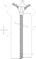
- 1 is a schematic top view of a slide fastener attached to a fabric.
- FIG. 1 is a schematic cross-sectional view of a slide fastener attached to a fabric.
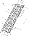
- FIG. 1 is a schematic partial perspective view of a fastening part, showing an attachment surface provided on one side in the thickness direction thereof;
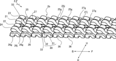
- FIG. 1 is a schematic partial perspective view of a fastening part, showing an engagement structure provided on the opposite side of the fastening part from the mounting surface in the thickness direction.
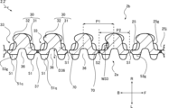
- FIG. FIG. 2 is a schematic side view of a fastening part, in particular illustrating an engaging element row, a recess, and a slit.
- FIG. 7 is a schematic cross-sectional view of the fastening part taken along the dashed line in FIG. 6 .
- FIG. 13 is a schematic diagram showing how the left and right fastening parts are engaged and disengaged by the forward and backward movement of the slider.
- FIG. FIG. 1 is a manufacturing process diagram of a fastening part.
- FIG. 1 is a process diagram of attaching fastening parts to fabric.
- FIG. 1 is a process diagram of attaching fastening parts to fabric.
- FIG. 1 is a process diagram of attaching fastening parts to fabric.
- 13 is a diagram showing an installation process for another example in which an intermediate sheet is provided between the fabric and the fastening parts.
- 11 is a schematic diagram of a slide fastener according to another embodiment.
- FIG. FIG. 4 is a schematic cross-sectional view of a slide fastener according to another embodiment.
- FIG. 2 is a partial perspective view of the fastening device.
- the direction of movement of the slider 8 that opens and closes the slide fastener 1 is defined as the front-to-rear direction (see the double-headed arrow FB in FIG. 1).
- the direction that is equal to the width direction of the slide fastener 1 and perpendicular to the front-to-rear direction is defined as the left-to-right direction (see the double-headed arrow LR in FIG. 1).
- the direction that is equal to the thickness direction of the slide fastener 1 and perpendicular to the front-to-rear direction is defined as the up-to-down direction. Note that the up-to-down direction is perpendicular to both the front-to-rear and left-to-right directions.
- the up-to-down direction does not necessarily mean the vertical direction (direction of gravity).
- the up-to-down direction with respect to the slide fastener 1 is included in the horizontal direction (perpendicular to the vertical direction). In this way, the directions referred to in this specification are unrelated to the vertical direction.
- Figure 1 is a schematic perspective view of a slide fastener 1 according to one embodiment of the present disclosure.
- Figure 2 is a schematic top view of the slide fastener 1 attached to a piece of fabric as an article 9.
- Figure 3 is a schematic cross-sectional view of the slide fastener 1 attached to a piece of fabric.
- the slide fastener 1 has a pair of left and right fastening parts 2, 2' as a fastening device 2A, and a slider 8 that can move forward and backward to engage and disengage the pair of left and right fastening parts 2, 2'.
- the left and right fastening parts 2, 2' are engaged by the forward movement of the slider 8, and the left and right fastening parts 2, 2' are disengaged by the backward movement of the slider 8.
- the left and right fastening parts 2, 2' can be engaged as a hook-to-hook type.
- the fastening parts 2, 2' are typically flexible resin parts, such as polyester.
- the fastening parts 2, 2' can be mass-produced by various molding techniques due to their regular structure in the longitudinal direction.
- the fastening parts 2, 2' By manufacturing the fastening parts 2, 2' very long (e.g., 10 m), the fastening parts 2, 2' can be cut out at any length (e.g., 50 cm). Being able to manufacture the fastening parts 2, 2' without considering the final product length is one advantage in terms of mass production. Depending on the application, it may be possible to manufacture the fastening parts 2, 2' harder and reduce their flexibility.
- the slider 8 has an upper wing 81, a lower wing 82, and a connecting post 83 that extends in the vertical direction and connects the front ends of the upper wing 81 and the lower wing 82, thereby defining a Y-shaped passage for the left and right fastening parts 2, 2'.
- the slider 8 is typically made of resin, metal, or ceramics.
- An upper flange wall 86 that stands downward is provided on the left and right side edges of the upper wing 81.
- a lower flange wall 87 that stands upward is provided on the left and right side edges of the lower wing 82. In this way, the movement paths of the left and right fastening parts 2, 2' in the width direction of the slider 8 are restricted.
- the vertical distance between the upper wing 81 and the lower wing 82 is designed to correspond to the width of the fastening parts 2, 2', as described below.
- the fastening parts 2, 2' are long parts that can be attached directly to the edge 91 of the article 9 or via an intermediate material (e.g., a flexible thin material such as another fabric) (see Figures 2 and 3).
- the article 9 to which the fastening parts 2, 2' are directly attached is a highly flexible fabric such as the fabric of a garment, the fabric of a bag, or the fabric of a shoe.
- the edge 91 of the article 9 is an edge that defines an opening that is opened and closed by the slide fastener 1. In some cases, the edge 91 is a folded edge formed by folding the fabric, which promotes efficient sewing of the fastening parts 2, 2' to the fabric as described below.
- the fabric When the fabric is folded, the fabric has a main fabric 92 and a secondary fabric 93 (see Figure 3), which are overlapped and a folded edge is formed between them.
- the main fabric 92 and the secondary fabric 93 can be sewn together with one or more sewing threads 200 along the side edge 95 of the secondary fabric opposite the folded end.
- the width W2 of the fastening parts 2, 2' in the vertical direction is greater than the width W91 of the article 9 (the laminated thickness of the main fabric 92 and the secondary fabric 93).
- the protruding height H2 of the fastening parts 2, 2' from the main surface of the article 9 is 1 cm or less (i.e., within the range of 0 to 1 cm), or 0.8 cm or less (i.e., within the range of 0 to 0.8 cm).
- the main surface of the article 9 means either its upper surface or its lower surface.
- width W2 of the fastening parts 2, 2' is equal to or less than the width W91 of the article 9 (the laminated thickness of the main fabric 92 and the secondary fabric 93) is also envisioned.
- FIG 4 is a schematic partial perspective view of the fastening parts 2, 2', showing the mounting surface 2a provided on one side in the thickness direction.
- the fastening parts 2, 2' are formed in mirror symmetry with respect to the center line CX.
- Figure 5 is a schematic partial perspective view of the fastening parts 2, 2', showing the engagement structure 2b provided on the opposite side of the mounting surface 2a in the thickness direction.
- Figure 6 is a schematic side view of the fastening parts 2, 2', in particular, the engagement element rows 21-24, the recess 55, and the slits S1, S2 are illustrated.
- Figure 7 is a schematic cross-sectional view of the fastening parts 2, 2' along the dashed line in Figure 6.
- the directions related to the fastening parts 2, 2' can be associated with the directions related to the slide fastener 1 as follows.
- the longitudinal direction of the fastening parts 2, 2' coincides with the front-rear direction of the slide fastener 1.
- the width direction of the fastening parts 2, 2' corresponds to the vertical direction of the slide fastener 1.
- the thickness direction of the fastening parts 2, 2' corresponds to the horizontal direction of the slide fastener 1.
- the fastening parts 2, 2' have an attachment surface 2a (FIG. 4) provided on one side in the thickness direction perpendicular to the longitudinal direction, and an engagement structure 2b provided on the opposite side of the attachment surface 2a in the thickness direction of the fastening parts 2, 2' (FIG. 5).
- the thickness (thickness direction) of the fastening parts 2, 2' can be defined as the height (height direction) of the engagement structure 2b from the attachment surface 2a.
- the engagement structure 2b of the fastening parts 2, 2' is provided so as to face or abut the engagement structure of the mating fastening part, and can be engaged therewith.
- the attachment surface 2a of the fastening parts 2, 2' is provided so as to at least partially face or at least partially abut the edge portion 91 of the article 9 to which the fastening parts 2, 2' are attached, and can be attached thereto.
- the attachment surface 2a may have at least a partially flat surface, but should not be limited to this aspect.
- the flat surface of the attachment surface 2a may be oriented perpendicular to the left-right direction in the slide fastener 1.
- the engagement structure 2b includes one or more rows of engagement elements in which the engagement elements 30 are arranged along the longitudinal direction of the fastening parts 2, 2', and in the illustrated example includes four rows of engagement elements 21-24 arranged in parallel in the width direction of the fastening parts 2, 2' (see, for example, Figures 4 to 6).
- the engagement element rows 21-24 may be distinguished by being called the first to fourth engagement element rows 21-24, respectively.
- Each engagement element 30 is hook-shaped (not loop-shaped) and includes a base 31 standing on the side opposite the mounting surface 2a and at least one protrusion 32 protruding from the base 31 along the longitudinal direction of the fastening parts 2, 2' (see, for example, Figure 7).
- a receiving space 33 is formed to receive the engagement element of the mating fastening part.
- the width W33 of the receiving space 33 in the thickness direction of the fastening parts 2, 2' can gradually increase as it moves away from the base 31 along the protruding direction of the protrusion 32.
- the engaging element rows 21, 23, in which the projections 32 protrude in opposite directions relative to the longitudinal direction of the fastening parts 2, 2', can be arranged adjacent to each other as a pair.
- the force required to engage or disengage the fastening parts 2, 2' increases, and the lateral pull strength of the slide fastener 1 can be increased.
- the arrangement direction of the engaging elements 30 in the engaging element rows 21-24 coincides with the longitudinal direction of the fastening parts 2, 2'.
- the arrangement direction of these engaging element rows 21-24 coincides with the width direction of the fastening parts 2, 2'.
- the structure of the fastening parts 2, 2' (particularly the structure of the engaging element rows 21-24) can be described as being composed of alternatingly connected engaging elements 30 and connecting portions 70 (see FIG. 7).
- the connecting portions 70 are thin portions that connect the engaging elements 30.
- the minimum thickness of the fastening parts 2, 2' is determined by the upper and lower surfaces of the connecting portions 70.
- a groove 36 which will be described later, may be formed between adjacent connecting portions 70 in the longitudinal direction of the fastening parts 2, 2'.
- a groove 37 which will be described later, and slits S1 and S2 may be formed in each connecting portion 70.
- the fastening parts 2, 2' may further include a covering portion 27 extending in the longitudinal direction thereof.
- the covering portion 27 may be a single continuous portion or a portion divided into multiple portions along the longitudinal direction of the fastening parts 2, 2'.
- the fastening parts 2, 2' are attached directly or via an intermediary to the edge 91 of the article 9 at their covering portions 27 other than the locations where their engaging element rows 21-24 are formed.
- the covering portion 27 is provided between adjacent engaging element rows (e.g., engaging element row 21 and engaging element row 22) in the width direction of the fastening parts 2, 2', and is preferably provided on the center line CX of the fastening parts 2, 2'.
- the sewing thread 96 for sewing the edge portion 91 of the attachment portion 27 may be present or included in the plane PL0 located at the center of thickness of the edge portion 91.
- the main fabric 92 and the sub fabric 93 are arranged on both sides of the plane PL0.
- the covering portion 27 may be formed thinner than the engaging element 30 in the thickness direction of the fastening parts 2, 2'.
- a sewing needle can be pierced through the covering portion 27 with less force.
- the fastening parts 2, 2' are welded to the edge portion 91, the heat capacity of the covering portion 27 is reduced, promoting smoother welding.
- the covering portion 27 may be formed thinner than the connecting portion 70 in some cases.
- the covering portion 27 may be provided as a thickness portion having a (constant or different) thickness from the bottom surface 53g of the receiving groove 53 described below, or as a wall having a (constant or different) height from the bottom surface 53g of the receiving groove 53 described below.
- the covering portion 27 may be in contact with the article 9 directly at the bottom surface 53g of the receiving groove 53.
- the attachment portion 27 may be formed narrower than any of the engaging element rows 21-24 in the width direction of the fastening parts 2, 2'. This facilitates forming the engaging element rows 21-24 (and each engaging element 30) with the desired wide width.
- the first and third engaging element rows 21, 23 are immediately adjacent to each other in the width direction of the fastening parts 2, 2' with a gap smaller than the attachment portion 27, and the second and fourth engaging element rows 22, 24 are immediately adjacent to each other with a gap smaller than the attachment portion 27, which facilitates high-density arrangement of the engaging element rows.
- At least one recess 55 is formed in the attachment portion 27 to receive the stitch 97 of the sewing thread 96 for sewing the fastening parts 2, 2' to the edge portion 91.
- the attachment portion 27 is formed as a wall having at least one recess 55 formed on the top surface.
- a plurality of recesses 55 may be provided at a predetermined pitch (corresponding to the stitch 97 pitch) along the longitudinal direction of the fastening parts 2, 2' (more preferably, the center line CX of the fastening parts 2, 2').
- Each recess 55 of the plurality of recesses 55 is preferably long in the longitudinal direction of the fastening parts 2, 2'.
- a sewing needle penetrates the thinned portion of the fastening parts 2, 2' due to the recess 55, making it easier to sew the fastening parts 2, 2' to the article 9. It is also possible to provide additional recesses 55 in the fastening parts 2, 2' at locations other than the attachment portion 27.
- the attachment portion 27 can be provided at locations other than between the first engaging element row 21 and the second engaging element row 22 that are adjacent in the width direction of the fastening parts 2, 2'.
- the fastening parts 2, 2' can have guide walls 25, 26 on both sides (typically, on both sides of the fastening parts 2, 2') that sandwich the engaging element rows 21-24 in the width direction.
- the guide walls 25, 26 can be provided at the position farthest from the center line CX of the fastening parts 2, 2' in the width direction of the fastening parts 2, 2'.
- the guide wall 25 can contact one of the lower surface of the upper wing plate 81 and the upper surface of the lower wing plate 82 of the slider 8, and the guide wall 26 can contact the other of the lower surface of the upper wing plate 81 and the upper surface of the lower wing plate 82 of the slider 8, thereby assisting the smooth movement of the slider 8 along the fastening parts 2, 2' and preventing the engaging element 30 from being damaged by a collision between the slider 8 and the engaging element 30.
- the engaging element rows 21-24, the guide walls 25, 26, and the attachment portion 27 are arranged in the vertical direction.
- Guide wall 25 and one or more of guide walls 26 may be configured as a wall row in which a plurality of walls are provided at a predetermined pitch along the longitudinal direction of fastening parts 2, 2' so as not to reduce the flexibility of fastening parts 2, 2'.
- attachment portion 27 Referring to FIG. 5, guide wall 25 has wall portions 25g arranged at a predetermined pitch (equal to the arrangement pitch of engaging elements 30) in the longitudinal direction of fastening parts 2, 2', and grooves 25j are formed between them. Groove 25j is spatially connected to receiving space 33 formed between the above-mentioned engaging elements 30 in the width direction of fastening parts 2, 2'.
- guide wall 25 also applies to guide wall 26, where wall portion 25g is replaced with wall portion 26g and groove 25j is replaced with groove 26j.
- the explanation given for the guide wall 25 also applies to the attachment portion 27, where the wall portion 25g is replaced with the wall portion 27g and the groove 25j is replaced with the groove 27j. In this way, the flexibility of the fastening parts 2, 2' can be increased.
- the mounting surface 2a is provided with at least one guide protrusion 51, 52 disposed between the upper and lower flange walls 86, 87 of the slider 8.
- the guide protrusions 51, 52 provided on the mounting surface 2a of each fastening part 2, 2' are disposed between the upper and lower upper and lower flange walls 86, 87 of the slider 8.
- two guide protrusion rows 61, 62 in which the guide protrusions 51, 52 are disposed in the longitudinal direction of the fastening parts 2, 2' are provided on the mounting surface 2a (see FIG. 4).
- the guide protrusions 51, 52 are positioned away from both ends of the fastening parts 2, 2' in the width direction of the fastening parts 2, 2' to form guide surfaces 56, 57 at both ends of the fastening parts 2, 2' in the width direction.
- the guide surfaces 56, 57 face or contact the upper and lower flange walls 86, 87 of the slider 8, thereby restricting the movement of the fastening parts 2, 2' in the width direction of the slider 8 and promoting smooth movement of the slider 8.
- the guide surfaces 56, 57 are typically formed as flat surfaces, but are not limited to this.
- Each guide protrusion 51 has a first side 51p and a second side 51q in the width direction of the fastening parts 2, 2'.
- each guide protrusion 52 has a first side 52p and a second side 52q in the width direction of the fastening parts 2, 2'.
- the first side 51p of the guide protrusion 51 faces or contacts the lower surface of the upper flange wall 86 to assist in smooth movement of the slider 8.
- the first side 52p of the guide protrusion 52 faces or contacts the upper surface of the lower flange wall 87 to assist in smooth movement of the slider 8.
- the second side 51q of the guide protrusion 51 faces the opposite side to the first side 51p, and is positioned opposite the second side 52q of the guide protrusion 52 across the center line CX of the fastening parts 2, 2'.
- the second side surface 52q of the guide protrusion 52 faces the opposite side surface 52p of the first side surface 52p, and is disposed opposite the second side surface 51q of the guide protrusion 51 across the center line CX of the fastening parts 2, 2'.
- a bottom surface 53g of the receiving groove 53 of the edge portion 91 is formed between the second side surfaces 51q, 52q of the guide protrusions 51, 52.
- the first and second side surfaces of the slide fastener 1 shown in FIG. 1 can alternatively be referred to as upper and lower surfaces.
- the provision of the above-mentioned guide protrusions 51, 52 helps to ensure a sufficiently wide vertical distance between the upper flange wall 86 and the lower flange wall 87 (see FIG. 3). Specifically, there is a gap between the main fabric 92 and the upper flange wall 86, which reduces or avoids wear thereon. Additionally or alternatively, there is a gap between the secondary fabric 93 and the lower flange wall 87, which reduces or avoids wear thereon. In some cases, the distance between the lower surface of the upper flange wall 86 and the upper surface of the lower flange wall 87 is slightly larger than the distance W9 (see FIG. 4) between the first side surfaces 51p, 52p of the guide protrusions 51, 52 of the fastening parts 2, 2'.
- the fastening parts 2, 2' can be more stably supported by the edge portion 91 of the article 9.
- the guide protrusions 51, 52 can also be connected to each other in the width direction of the fastening parts 2, 2' to form a single guide protrusion.
- a groove 36 penetrating (removing) the base 31 of the engaging element 30 can be recessed in the mounting surface 2a.
- the groove 36 extends in the width direction of the fastening parts 2, 2' with a constant or variable depth D36.
- the groove 36 is formed in the longitudinal direction of the fastening parts 2, 2' with the same pitch P1 as the pitch P1 of the engaging elements 30.
- the pitch of the groove 36 can also be a multiple of the pitch of the engaging elements 30.
- the groove 36 extends over the entire width of the fastening parts 2, 2' in the width direction, and can also penetrate, for example, the guide walls 25, 26 and the walls 25g, 26g, 27g of the attachment part 27.
- each groove 36 is sandwiched between adjacent guide protrusions 51 arranged in the same direction, and similarly, between guide protrusions 52.
- grooves 37 that thin the fastening parts 2, 2' can be formed between adjacent engaging elements 30 in the longitudinal direction of the fastening parts 2, 2'.
- Grooves 36 and grooves 37 are formed alternately in the longitudinal direction of the fastening parts 2, 2'.
- Groove 36 can be formed deeper than groove 37 by the amount that it penetrates the base 31 of the engaging element 30, but this is not necessarily the case.
- the pitch P2 of groove 37 is the same as the pitch P1 of the engaging elements 30, but can also be a multiple of it.
- a plurality of slits S1, S2 extending in the width direction of the fastening parts 2, 2' can be formed.
- Each of the plurality of slits S1, S2 is located between adjacent engaging elements 30 in the longitudinal direction of the fastening parts 2, 2'.
- the fastening parts 2, 2' become easier to deform (for example, easier to bend in the left-right direction and/or up-down direction, or easier to twist).
- each of the plurality of slits S1, S2 is formed to a length exceeding half the width of the fastening parts 2, 2'.
- the slit S1 is an upper slit extending downward from the upper edge of the fastening parts 2, 2' toward the lower edge.
- the slit S2 is a lower slit extending upward from the lower edge of the fastening parts 2, 2' toward the upper edge.
- the fastening parts 2, 2' have an attachment surface 2a (FIG. 4) provided on one side in the thickness direction perpendicular to the longitudinal direction, and an engagement structure 2b provided on the opposite side of the attachment surface 2a in the thickness direction of the fastening parts 2, 2' (FIG. 5).
- the engagement structure 2b includes one or more engagement element rows 21-24 in which engagement elements 30 are arranged along the longitudinal direction of the fastening parts 2, 2'. Each engagement element 30 is provided upright on the opposite side to the attachment surface 2a. In this way, a fastening part 2, 2' is provided that can be directly attached to an article 9 and is suitable for mass production.
- the fastening parts 2, 2' can be directly attached to the edge 91 of the article 9. Therefore, by using these fastening parts 2, 2', a slide fastener 1 can be constructed without fastener tape.
- the fastening parts 2, 2' are selectively attached to the article 9 at one location of the attachment portion 27 in its width direction (which may include the bottom surface 53g of the receiving groove 53).
- the attachment portion 27 may be elongated in the longitudinal direction of the fastening parts 2, 2'.
- the left fastening part 2 is a part long in the front-rear direction sewn by a sewing thread 96 directly or via an intervening object to the left edge of the opening of the article 9 to which the slide fastener 1 is attached, and includes at least one row of left engaging elements arranged along the longitudinal direction of the left fastening part 2, and the left engaging elements protrude to the right side opposite the left edge of the opening.
- the right fastening part 2' is a part long in the front-rear direction sewn by a sewing thread 96 directly or via an intervening object to the right edge of the opening of the article 9, and includes at least one row of right engaging elements arranged along the longitudinal direction of the right fastening part 2', and the right engaging elements protrude to the left side opposite the right edge of the opening.
- the guide protrusions 51, 52 are sandwiched between the upper and lower flange walls 86, 87 on the top and bottom of the slider 8, promoting stable sliding movement of the slider 8. Thanks to the grooves 36 and/or grooves 37 formed in the fastening parts 2, 2', the fastening parts 2, 2' have increased flexibility, thereby reducing the sliding resistance of the slider 8.
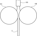
- the fastening parts 2, 2' can be manufactured by supplying molten resin from the discharge section 103 between two adjacent die wheels 101, 102 as shown in FIG. 9. Although not shown, a cavity capable of molding the engagement structure 2b of the fastening parts 2, 2' is formed on one peripheral surface of the die wheels 101, 102, and a cavity capable of molding the structure on the mounting surface 2a side of the fastening parts 2, 2' is formed on the other peripheral surface.
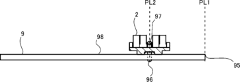
- the fastening part 2 can be directly attached to the fabric by the procedure shown in Figures 10 to 12 (the same applies to the fastening part 2').
- the fastening part 2 is sewn to the fabric (e.g., at its attachment part 27) using sewing thread 96 along the side edge 95 at a position away from the side edge 95 of the fabric inward (i.e., at a position on a vertical plane PL2 parallel to the vertical plane PL1 relative to the side edge 95).
- the fastening part 2 is selectively attached to a predetermined part of the fabric (the part that becomes the folded end as described below) at its attachment part 27, and is not attached to the fabric at other parts (e.g., the part where the engaging element rows 21 to 24 are provided). Note that when the fastening part 2 is placed on the placement surface 98 of the article 9, the protruding direction of the engaging element 30 coincides with the direction away from the placement surface 98 of the article 9 (e.g., the perpendicular direction).
- Various sewing methods can be used, such as lock stitching, single chain stitching, and double chain stitching.
- the sewing direction of the sewing thread 96 corresponds to the longitudinal direction of the fastening part 2.
- the fastening part 2 can be fixed to the article 9 by ultrasonic welding.
- the fastening part 2 is placed on the placement surface 98 of the article 9 so that the mounting surface 2a of the fastening part 2 (e.g., the bottom surface 53g of the receiving groove 53 between the guide protrusions 51 and 52) contacts the placement surface 98 of the article 9.
- the shape of the anvil is optimized to ensure reliable contact between the fastening part 2 and the article 9.
- the anvil is provided with a protrusion that protrudes between the guide protrusions 51 and 52.
- the horn is brought into contact with the fastening part 2 (e.g., its attachment portion 27) to supply ultrasonic vibrations to the fastening part 2.
- the fastening part 2 e.g., the bottom surface 53g of the receiving groove 53
- the article 9 are welded to each other on the side opposite the contact position of the horn (e.g., the attachment portion 27).
- the horn is moved in the longitudinal direction of the fastening part 2, or the fastening part 2 is moved relative to the horn that is stationary at a predetermined position. In this way, a welded portion can be formed continuously or intermittently in the longitudinal direction of the fastening part 2, thereby fixing the fastening part 2 to the article 9.
- Both the fastening part 2 and the article 9 are made of resin.
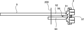
- the fabric is folded to form a folded end (the above-mentioned edge 91) to which the fastening part 2 is sewn.
- the secondary fabric 93 is overlapped on the main fabric 92 to form the folded end, and at the same time, the fastening part 2 is rotated 90° relative to the placement surface 98 of the article 9 and oriented.
- the engaging element 30 of the fastening part 2 changes its protruding direction by 90° and is oriented so as to be perpendicular to the thickness direction of the part of the fabric other than the folded end (e.g., the main fabric 92).
- the protruding direction of the engaging element 30 changes from perpendicular to the placement surface 98 of the article 9 (e.g., the main fabric 92) to parallel.
- the engaging element rows 21, 22 on both sides of the attachment portion 27 are juxtaposed in the thickness direction of the main fabric 92 and arranged on both sides of the plane PL0 as described above, thereby obtaining the same benefits as described above (see FIG. 3).
- the process of forming the folded end shown in FIG. 11 can be performed before the attachment process shown in FIG. 10.
- the folded end to which the fastening part 2 is to be sewn is formed by folding the fabric. This method may be more suitable for ultrasonic welding.
- FIG. 11 the process of forming the folded end shown in FIG. 11 can be performed before the attachment process shown in FIG. 10.
- the folded end to which the fastening part 2 is to be sewn is formed by folding the fabric. This method may be more suitable for ultrasonic welding.
- parts of the fabric e.g., the main fabric 92 and the sub fabric 93
- parts of the fabric are sewn together near the side edge 95 of the fabric with a sewing thread 200.
- the fastening part 2 may be attached to it in a manner different from that described above.
- the fastening parts 2, 2' can be sewn to the fabric via an intermediate sheet 99.
- the intermediate sheet 99 can be a thin material such as fabric or a resin sheet.
- the fabric can be folded over in the same manner as in FIG. 11.
- the slide fastener 1 has left and right fastening parts 2, 2' and a slider 8, and the left and right fastening parts 2, 2' can be engaged and disengaged according to the forward and backward movement of the slider 8.
- the fastening parts 2, 2' are directly attached to the article 9, and the omission of the woven and/or knitted fastener tape promotes weight reduction and/or cost reduction.
- the fastening parts 2, 2' have first and second engaging element rows 21, 22, a mounting portion 27, and a substrate 40. Each of the first and second engaging element rows 21, 22 includes a plurality of engaging elements 30 arranged at a predetermined pitch.
- the fastening parts 2, 2' include the first engaging element row 21, the mounting portion 27, and the second engaging element row 22 in the width direction, but do not have the third and fourth engaging element rows 23, 24 and the guide walls 25, 26 described above (i.e., a three-row structure, i.e., two rows of the first and second engaging element rows 21, 22 + one row of the mounting portion 27), making them narrower. This improves the flexibility of the fastening device 2A when attached to the article 9. It is also possible to omit the third and fourth engaging element rows 23, 24 but not omit the guide walls 25, 26.
- each engaging element 30 is provided standing on the opposite side of the mounting surface 2a.
- a group of engaging elements 30 are connected to a common attachment portion 27 and/or a common substrate 40 to ensure mechanical integrity and strength.
- Adjacent engaging elements 30 in the longitudinal direction of the fastening parts 2, 2' are connected by a connecting portion 70 that is a part of the substrate 40.
- the inclusion of the substrate 40 in the fastening parts 2, 2' promotes smooth molding of the fastening parts 2, 2' and/or smooth movement of the slider 8, but of course the whole or part of the substrate 40 can be omitted.
- all of the connecting portions 70 of the substrate 40 are omitted, and in other cases, one or more selected connecting portions 70 of all the connecting portions 70 of the substrate 40 are omitted.
- the connection between the engaging elements 30 is ensured only by the attachment portion 27, and in the latter case, the connection between the engaging elements 30 is ensured by the attachment portion 27 and one or more selected connecting portions 70.
- a slit may be formed in the connecting portion 70, or at least a portion of the connecting portion 70 may be punched out to form an opening and/or a notch. It is also possible to provide guide protrusions 51 and 52 on the mounting surface 2a, but if they are formed flat as in the illustrated example, the structure of the molding die such as the die wheel can be simplified.
- the attachment portion 27 is a protrusion extending in the longitudinal direction of the fastening parts 2, 2' between the first and second engaging element rows 21, 22 and protruding on the opposite side to the mounting surface 2a.
- the attachment portion 27 is formed on the substrate 40 lower than the engaging elements 30, but has a thickness greater than the thickness of the substrate 40 (TH27>TH40). This provides the necessary strength when the fastening parts 2, 2' are sewn to the article 9, a sufficient thickness to withstand heat welding, prevention of breakage when released from the die wheel in the manufacturing process, or other advantages.
- the attachment portion 27 can optionally include a reinforcing material 28 such as a braided cord, twisted cord, or nonwoven fabric piece extending in its extension direction, thereby increasing its mechanical strength and/or its attachment strength to the article 9.
- a reinforcing material 28 such as a braided cord, twisted cord, or nonwoven fabric piece extending in its extension direction, thereby increasing its mechanical strength and/or its attachment strength to the article 9.
- the reinforcing material 28 includes any one of a knitted cord, a twisted cord, and a piece of nonwoven fabric, or any combination of these, when the fastening parts 2, 2' are sewn together, even if a needle is inserted into the resin part of the attachment part 27, the strength reduction is suppressed.
- the reinforcing material 28 does not need to be embedded in the attachment part 27, and may be fixed to the attachment part 27. In this case, the reinforcing material 28 appears on the exterior of the fastening parts 2, 2' and is visible.
- Each engaging element 30 included in the first and second engaging element rows 21, 22 has two protrusions 32 that protrude on both sides in opposite directions in the longitudinal direction of the fastening parts 2, 2'. That is, instead of assigning protrusions 32 that protrude in opposite directions and only on one side to the two engaging element rows of the first and third engaging element rows 21, 23, a protrusion 32 that protrudes on both sides is assigned to a single engaging element row. This makes it possible to improve the flexibility of the fastening device 2A without causing a significant decrease in the engaging force between the engaging elements 30 of the fastening parts 2, 2'.
- the two protrusions 32 mentioned above include a front protrusion 32a that protrudes forward compared to the base 31, and a rear protrusion 32b that protrudes rearward compared to the base 31.
- the engaging elements 30 are arranged at a first pitch in the first engaging element row 21 and at a second pitch in the second engaging element row 22, and in some cases the first pitch and the second pitch are equal, and in other cases they are different.
- the first and second pitches equal, the distinction between the first and second engaging element rows 21, 22 (or the directionality thereof) is eliminated and/or a good balance between the first and second engaging element rows 21, 22 in terms of the target engagement force is ensured.
- the engaging elements 30 of the first and second engaging element rows 21, 22 can be arranged at least partially opposite each other in the width direction of the fastening parts 2, 2'.
- first and second engaging element rows 21, 22 are formed as mirror images, and therefore the engaging elements 30 of the first and second engaging element rows 21, 22 are provided as opposing pairs in the width direction of the fastening parts 2, 2', with the same benefits as described above.
- Each of the engagement elements 30 in the first and second engagement element rows 21, 22 has a flat opposing surface 38.
- the spacing between the opposing surfaces 38 typically coincides with the maximum width W27 of the attachment portion 27, but is not necessarily limited to this.
- the spacing between the opposing surfaces 38 can be changed as appropriate depending on the thickness of the needle used when sewing the article 9.
- the opposing surfaces 38 are oriented approximately perpendicular to the plane on which the substrate 40 exists, but can also be inclined.
- Each engagement element 30 has an opposite surface 39 on the opposite side to the opposing surface 38.
- the opposite surface 39 faces or comes into contact with the upper wing 81 or lower wing 82 of the slider 8 when the engagement element 30 enters the slider 8.
- the opposite surface 39 is an approximately flat surface that exists in a plane perpendicular to the up-down direction, and therefore smooth sliding of the slider 8 is ensured.
- the engaging element 30 has a symmetrical narrowed shape, for example, a base 41, a neck 42, and a head 43, and is narrowed at the neck 42.
- the engaging element 30 can have two protrusions 32 that protrude on both sides of the fastening parts 2, 2' in the longitudinal direction, rather than on one side, as described above.
- the base 41 has a width W41 that gradually decreases toward the head 43.
- the neck 42 is provided between the base 41 and the head 43, and has a width W42 that is narrower than both of them.
- the head 43 has a width W43 that gradually increases as it moves away from the neck 42, and then gradually decreases.
- the engaging element 30 has a width in the longitudinal direction of the fastening parts 2, 2', a width (which may also be called a thickness) in the width direction of the fastening parts 2, 2', and a height in the thickness direction of the fastening parts 2, 2'.
- the space between adjacent engaging elements 30 in the longitudinal direction of the fastening parts 2, 2' includes the receiving space 33.
- the head 43 of the engaging element 30 of the fastening part 2 is inserted between the necks 42 of adjacent engaging elements 30 of the fastening part 2'.
- the base 41 has two side surfaces 41a, 41b standing from the substrate 40, each of which connects the opposing surface 38 to the opposite surface 39.
- a gap that communicates with the receiving space 33 is formed between the opposing side surfaces 41a, 41b between the adjacent engaging elements 30, and therefore sufficient flexibility of the fastening parts 2, 2' is ensured.
- the engaging element 30 can optionally have at least two shoulder projections 44 on both sides of the neck 42 and a receiving groove 45 for receiving the shoulder projections 44 of the engaging element 30, and has sufficient resistance to being pushed up in the vertical direction of the slide fastener 1.
- the shoulder projection 44 of one engaging element 30 is inserted into the receiving groove 45 of the other engaging element 30, limiting the vertical displacement of both engaging elements 30.
- the receiving groove 45 is recessed in the opposing surface 38 by cutting out the edge of the head 43, and is formed over the entire width of the head 43.
- the maximum width W44 of the shoulder projections 44 is 1/2 or less of the maximum width W30 of the engaging element 30, which allows the receiving groove 45 to be formed shallow (in the width direction of the fastening parts 2, 2') and suppresses a decrease in the mechanical strength of the head 43.
- the fastening parts 2, 2' described above with reference to Figures 14 to 19 can be manufactured using the same manufacturing method as that shown in Figure 9, and can be attached using the same attachment method as that shown in Figures 10 to 12, so duplicated explanations will be omitted.
- the mounting surface 2a contacts the item 9 at its receiving groove 53 (particularly the bottom surface 53g), but does not contact the item 9 at the guide surfaces 56 and 57.
- the mounting surface 2a can be understood as a whole as long as it includes an area that faces or contacts the item 9.
Landscapes
- Slide Fasteners (AREA)
Priority Applications (2)
| Application Number | Priority Date | Filing Date | Title |
|---|---|---|---|
| JP2024576184A JPWO2024166605A1 (https=) | 2023-02-06 | 2024-01-12 | |
| CN202480009250.3A CN120603514A (zh) | 2023-02-06 | 2024-01-12 | 紧固部件、拉链以及带紧固部件的布料的制造方法 |
Applications Claiming Priority (2)
| Application Number | Priority Date | Filing Date | Title |
|---|---|---|---|
| JP2023016425 | 2023-02-06 | ||
| JP2023-016425 | 2023-02-06 |
Publications (1)
| Publication Number | Publication Date |
|---|---|
| WO2024166605A1 true WO2024166605A1 (ja) | 2024-08-15 |
Family
ID=92262311
Family Applications (1)
| Application Number | Title | Priority Date | Filing Date |
|---|---|---|---|
| PCT/JP2024/000675 Ceased WO2024166605A1 (ja) | 2023-02-06 | 2024-01-12 | ファスニングパーツ、スライドファスナー、及びファスニングパーツ付き布地の製造方法 |
Country Status (3)
| Country | Link |
|---|---|
| JP (1) | JPWO2024166605A1 (https=) |
| CN (1) | CN120603514A (https=) |
| WO (1) | WO2024166605A1 (https=) |
Citations (3)
| Publication number | Priority date | Publication date | Assignee | Title |
|---|---|---|---|---|
| JP2016202761A (ja) * | 2015-04-27 | 2016-12-08 | Ykk株式会社 | スライドファスナー |
| US20200008542A1 (en) * | 2017-03-09 | 2020-01-09 | Young Gyo KIM | Multi airtight type rail zipper |
| JP6947829B2 (ja) * | 2017-08-22 | 2021-10-13 | Ykk株式会社 | ファスニングシステム及びファスニング装置 |
-
2024
- 2024-01-12 WO PCT/JP2024/000675 patent/WO2024166605A1/ja not_active Ceased
- 2024-01-12 CN CN202480009250.3A patent/CN120603514A/zh active Pending
- 2024-01-12 JP JP2024576184A patent/JPWO2024166605A1/ja active Pending
Patent Citations (3)
| Publication number | Priority date | Publication date | Assignee | Title |
|---|---|---|---|---|
| JP2016202761A (ja) * | 2015-04-27 | 2016-12-08 | Ykk株式会社 | スライドファスナー |
| US20200008542A1 (en) * | 2017-03-09 | 2020-01-09 | Young Gyo KIM | Multi airtight type rail zipper |
| JP6947829B2 (ja) * | 2017-08-22 | 2021-10-13 | Ykk株式会社 | ファスニングシステム及びファスニング装置 |
Also Published As
| Publication number | Publication date |
|---|---|
| CN120603514A (zh) | 2025-09-05 |
| JPWO2024166605A1 (https=) | 2024-08-15 |
Similar Documents
| Publication | Publication Date | Title |
|---|---|---|
| US11206901B2 (en) | Slide fastener-attached product, element member and manufacturing method of slide fastener-attached product | |
| CN102655777B (zh) | 拉链牙链带的缝制方法及拉链被覆制品的制造方法、以及拉链被覆制品及缝纫机压脚 | |
| US9038249B2 (en) | Slider for concealed slide fastener | |
| US9061882B2 (en) | Fastening member | |
| TWI627921B (zh) | Zipper-attached article and method of manufacturing the same with zipper | |
| TWI739213B (zh) | 鏈齒構件及具有拉鏈之製品 | |
| TWI834833B (zh) | 拉鏈鏈條及拉鏈 | |
| WO2024166605A1 (ja) | ファスニングパーツ、スライドファスナー、及びファスニングパーツ付き布地の製造方法 | |
| JP3243812U (ja) | スライドファスナー及びスライドファスナー付き製品 | |
| TWI724533B (zh) | 止擋構件、附有拉鏈之製品、及拉鏈 | |
| CN223994467U (zh) | 带止码拉链和带拉链产品 | |
| WO2026033601A1 (ja) | ファスニングパーツ、物品、及び物品の製造方法 | |
| JP7729994B2 (ja) | スライドファスナー用エレメント部材及びスライドファスナー付き製品 | |
| US20240415243A1 (en) | Fastener chain | |
| JP2025124267A (ja) | ファスナーストリンガー | |
| KR20250125268A (ko) | 은폐 슬라이드 파스너 | |
| WO2024105761A1 (ja) | ファスナー付き製品、ファスナー付き製品の製造方法、及び織込みファスナーストリンガー | |
| AU2014202484A1 (en) | Slider for hidden slide fastener |
Legal Events
| Date | Code | Title | Description |
|---|---|---|---|
| 121 | Ep: the epo has been informed by wipo that ep was designated in this application |
Ref document number: 24753052 Country of ref document: EP Kind code of ref document: A1 |
|
| WWE | Wipo information: entry into national phase |
Ref document number: 2024576184 Country of ref document: JP |
|
| WWE | Wipo information: entry into national phase |
Ref document number: 112025000105883 Country of ref document: IT |
|
| WWE | Wipo information: entry into national phase |
Ref document number: 202480009250.3 Country of ref document: CN |
|
| WWP | Wipo information: published in national office |
Ref document number: 202480009250.3 Country of ref document: CN |
|
| NENP | Non-entry into the national phase |
Ref country code: DE |
|
| 122 | Ep: pct application non-entry in european phase |
Ref document number: 24753052 Country of ref document: EP Kind code of ref document: A1 |