WO2024166453A1 - エアロゾルの捕集・検出用マイクロ流路デバイス、および、エアロゾルの捕集・検出方法 - Google Patents
エアロゾルの捕集・検出用マイクロ流路デバイス、および、エアロゾルの捕集・検出方法 Download PDFInfo
- Publication number
- WO2024166453A1 WO2024166453A1 PCT/JP2023/038729 JP2023038729W WO2024166453A1 WO 2024166453 A1 WO2024166453 A1 WO 2024166453A1 JP 2023038729 W JP2023038729 W JP 2023038729W WO 2024166453 A1 WO2024166453 A1 WO 2024166453A1
- Authority
- WO
- WIPO (PCT)
- Prior art keywords
- aerosol
- flow
- section
- microchannel device
- detecting
- Prior art date
- Legal status (The legal status is an assumption and is not a legal conclusion. Google has not performed a legal analysis and makes no representation as to the accuracy of the status listed.)
- Ceased
Links
Images










Classifications
-
- G—PHYSICS
- G01—MEASURING; TESTING
- G01N—INVESTIGATING OR ANALYSING MATERIALS BY DETERMINING THEIR CHEMICAL OR PHYSICAL PROPERTIES
- G01N1/00—Sampling; Preparing specimens for investigation
- G01N1/02—Devices for withdrawing samples
-
- G—PHYSICS
- G01—MEASURING; TESTING
- G01N—INVESTIGATING OR ANALYSING MATERIALS BY DETERMINING THEIR CHEMICAL OR PHYSICAL PROPERTIES
- G01N1/00—Sampling; Preparing specimens for investigation
- G01N1/02—Devices for withdrawing samples
- G01N1/22—Devices for withdrawing samples in the gaseous state
-
- G—PHYSICS
- G01—MEASURING; TESTING
- G01N—INVESTIGATING OR ANALYSING MATERIALS BY DETERMINING THEIR CHEMICAL OR PHYSICAL PROPERTIES
- G01N37/00—Details not covered by any other group of this subclass
Definitions
- This disclosure relates to a microfluidic device for collecting and detecting aerosols, and a method for collecting and detecting aerosols.
- Patent Document 1 discloses a method in which a threat substance such as an aerosol substance is attached to a substrate, illuminated with multiple photons, and the generated elastic scattered photons and Raman scattered photons are analyzed to analyze and identify the sample at the same time as the threat substance is attached to the substrate.
- Non-Patent Document 1 discloses a technology for identifying non-biological particles and aerosolized biological particles in real time by using an inertial impaction system to collide airborne pathogenic microorganisms with an impact plate and obtaining a fluorescent microscope image.
- Patent Document 2 discloses a method for collecting and measuring particles in exhaled breath, in which aerosols are collected on a solid surface (the surface of the collection plate of the impactor) and then the collection plate is recovered and used to measure the collected particles.
- Patent Documents 3 and 4 disclose a biological substance detection system, and Patent Documents 3 and 4, as well as Non-Patent Document 2, disclose a method for transferring collected aerosols into a liquid using a collection device and recovering them.
- Non-Patent Documents 3 and 4 disclose a liquid-based collection method for detecting aerosols, in which a two-phase fluid of aerosol and collection liquid is passed through a flow path to move particles from the gas phase to the liquid phase.
- Patent Document 1 employs a method that combines elastic scattering and Raman scattering when identifying threat substances attached to a substrate, which limits the flexibility of the detection method.
- Non-Patent Document 1 uses fluorescent microscope images to distinguish non-biological particles from biological particles. Therefore, with such a method of collecting aerosols on a solid surface and detecting them in real time, it is difficult to identify that specific aerosol particles are contained in a miscellaneous sample.
- a microchannel device for collecting and detecting aerosols comprising: an aerosol flow section that is a microchannel through which an aerosol flowing in from the outside flows and has a shape in which aerosol particles in the aerosol collide with a channel wall surface due to at least one of inertial force, vortex flow, and turbulence generated by the aerosol flow, and one or more microwells that are provided contiguous to the wall surface of the aerosol flow section against which the aerosol particles collide, and that hold therein a detection liquid for detecting the aerosol particles.
- the aerosol flow section may include a curved section having a curved flow channel shape as the section having the shape where aerosol particles in the aerosol collide with a flow channel wall surface.
- the aerosol flow section is simply configured to have a curved section, and thus the aerosol can collide with the flow channel wall surface due to inertial force or vortex flow, and the aerosol can be efficiently collected in a microwell.
- the aerosol flow section may include the curved portion having a flow channel shape of a spiral. With this configuration, the curved portions having a shape that causes aerosol particles to collide with a flow channel wall surface are arranged at a high density, thereby improving the efficiency of collecting aerosols.
- the microchannel device for collecting and detecting aerosols according to the above embodiment may further include a humidifying section for humidifying the aerosol flow section. With this configuration, the detection liquid in the microwells can be prevented from evaporating and decreasing when detecting aerosols. This allows the detection operation to be performed stably for a longer period of time.
- the humidifying section may be a water storage section that is provided in communication with the aerosol flow section and that stores water.
- water can be stored in the humidifying section beforehand prior to the operations of collecting and detecting aerosols, and therefore the operation for humidification can be simplified.
- the microchannel device for collecting and detecting aerosols of the above-mentioned form may further include an aerosol inflow section through which the aerosol flows from the outside into the microchannel device, and a communication flow path that communicates the aerosol inflow section with the aerosol flow section, and the water storage section may be provided in communication with the communication flow path.
- the microchannel device for collecting and detecting aerosols may further include a connection channel connecting the communicating channel and the water storage section, the communicating channel being formed to have a channel cross-sectional area larger than that of the connecting channel.
- a method for collecting and detecting an aerosol which comprises using the microchannel device for collecting and detecting an aerosol according to any one of (1) to (7) to fill the microwells with the detection liquid, generating a pressure difference between an upstream end and a downstream end in a flow direction of the aerosol in the aerosol flow section to cause the aerosol to flow in the aerosol flow section, collecting aerosol particles in the aerosol flowing in the aerosol flow section in the detection liquid in the microwells, and detecting the aerosol particles in the microwells.
- the aerosol is detected using the detection liquid placed in the microwell, various detection methods can be adopted as long as they are liquid-based detection methods, and the degree of freedom of the detection method can be increased and it can be used to detect various aerosols.
- the present disclosure can be realized in various forms other than those described above, for example, in the form of a method of using a microchannel device for collecting and detecting aerosols, or an aerosol detection apparatus including a microchannel device for collecting and detecting aerosols.
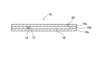
- FIG. 1 is a plan view showing a schematic configuration of a microchannel device according to a first embodiment.
- FIG. 1 is a cross-sectional view illustrating a schematic configuration of a microchannel device according to a first embodiment.
- FIG. 1 is an explanatory diagram showing an example of an aerosol collection and detection device.
- FIG. 1 is an explanatory diagram showing an example of aerosol detection using a microfluidic device.
- FIG. 1 is an explanatory diagram showing an example of aerosol detection using a microfluidic device.
- FIG. 11 is a plan view showing a schematic configuration of a microchannel device according to a second embodiment.
- FIG. 13 is a plan view showing a schematic configuration of a microchannel device according to a third embodiment.
- FIG. 13 is an explanatory diagram showing a state in which the entire microchannel device is filled with liquid.
- FIG. 13 is an explanatory diagram showing the microwells and the humidifying section filled with liquid.
- FIG. 1 is an explanatory diagram showing a state in which a microwell is filled with a liquid.
- FIG. 4 is an explanatory diagram showing the results of investigating the effect of humidifying an aerosol by a humidifying unit.
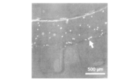
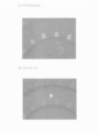
- Brightfield image of a site containing microwells Fluorescence image of the same field as in FIG. 11A.
- FIG. 13 is an explanatory diagram showing the results of measuring the luminance after 20 minutes.
- FIG. 13 is an explanatory diagram showing the state in which the fluorescence brightness was observed after 20 minutes.
- FIGS. 1A and 1B are explanatory diagrams showing a schematic configuration of a microchannel device 10 according to a first embodiment of the present disclosure.
- Fig. 1A shows a plan view
- Fig. 1B shows a cross-sectional view taken along the line B-B in Fig. 1A. It should be noted that Figs. 1A and 1B do not show accurate dimensional ratios of the various parts.
- the microchannel device 10 of this embodiment is a plate-like member with a microchannel formed therein, and is a device for collecting and detecting aerosols taken into the microchannel from the outside.
- the microchannel device 10 includes an aerosol flow section 12, a microwell 14, an aerosol inlet section 20, a communicating flow channel 16, and an aerosol outlet section 22.
- the aerosol flow section 12 is a micro flow path through which the aerosol flowing in from the outside flows.
- the aerosol flow section 12 has a shape that causes aerosol particles in the aerosol to collide with the flow path wall surface due to at least one of inertial force, vortex flow, and turbulence generated by the flow of the aerosol.
- the aerosol flow section 12 of this embodiment has a curved section in which the flow path shape is curved, and the aerosol flowing through the aerosol flow section 12 collides with the flow path wall surface of the curved section due to inertial force and vortex flow. More specifically, the aerosol flow section 12 has a curved section in which the flow path shape is a spiral shape.
- the microwell 14 is provided in continuity with the wall surface of the aerosol flow section 12 on which the aerosol particles collide, and is a structure for holding detection liquid for detecting aerosol particles inside. That is, the wall surface of the aerosol flow section 12 on which the aerosol collides and the wall surface of the microwell 14 are continuous, and the flow path constituting the aerosol flow section 12 communicates with the space inside the microwell 14.
- multiple microwells 14 are provided in a shape that protrudes so as to extend further outward from the outer peripheral wall surface of the spiral-shaped aerosol flow section 12.
- FIG. 1A shows the overall configuration of the microchannel device 10, and also shows an enlarged portion of the aerosol flow section 12 in which the microwell 14 is provided. Also, in FIG.
- the aerosol inlet section 20 is a structure for introducing an aerosol from the outside into the microchannel device 10, and is an opening that opens on the surface of the microchannel device 10.
- the communicating flow path 16 is a microchannel that communicates the aerosol inlet section 20 and the aerosol flow path 12.
- the communicating flow path 16 is formed as a straight flow path so as to connect the outer end of the aerosol flow path 12 formed in a spiral shape to the aerosol inlet section 20, but the communicating flow path 16 may have a shape other than a straight shape.
- the aerosol inlet section 20 may be provided at the end of the spiral-shaped aerosol flow path 12 without providing the communicating flow path 16.
- the aerosol outlet section 22 is a structure for discharging the aerosol that has passed through the micro-channel device 10 to the outside of the micro-channel device 10, and is an opening that communicates with the inner end of the aerosol flow section 12, which is formed in a spiral shape, and opens on the surface of the micro-channel device 10.
- a pressure difference is generated between the upstream end and downstream end of the aerosol flow direction in the aerosol flow section 12, i.e., between the aerosol inlet section 20 and the aerosol outlet section 22. This allows the aerosol to flow within the aerosol flow section 12 from the aerosol inlet section 20 side toward the aerosol outlet section 22 side.
- the method of creating a pressure difference between the aerosol inlet portion 20 and the aerosol outlet portion 22 is not particularly limited, and various methods can be adopted.
- a pump can be connected to the aerosol outlet portion 22 to generate suction force on the aerosol outlet portion 22 side.
- the aerosol in the atmosphere can be introduced into the aerosol flow portion 12.
- a syringe containing the aerosol to be detected can be connected to the aerosol inlet portion 20 side, and the aerosol can be introduced into the aerosol flow portion 12 by pushing the aerosol with the syringe.
- the exhaled breath can be blown into a tube connected to the aerosol inlet portion 20.
- the microchannels such as the aerosol flow section 12, the microwell 14, and the communicating flow section 16 may be formed so that the size of the flow section, that is, the flow section height or width, or the flow section diameter as the diameter of a circle having an area equivalent to the flow section cross-sectional area, is 1 ⁇ m or more and 1 mm or less. From the viewpoint of optimizing the flow section resistance when the aerosol flows, it is desirable that the flow section diameter of the aerosol flow section 12 is 100 ⁇ m or more. In the microwell 14, it is desirable that the flow section diameter of the surface perpendicular to the direction in which the aerosol flow section 12 protrudes outward from the outer wall surface of the aerosol flow section 12 is equal to or less than the flow section diameter of the aerosol flow section 12.
- the constituent material of the microchannel device 10 only needs to have the processability to form a microchannel.
- the constituent material of the microchannel device 10 when an optical method is adopted as the detection method using the microchannel device 10, the constituent material of the microchannel device 10 only needs to have transparency or translucency that allows the aerosol to be detected in the state where it is collected in the detection liquid in the microwell 14.
- transparency or translucency of the constituent material of the microchannel device 10 is not essential.
- the constituent material of the microchannel device 10 include silicone resins such as polydimethylsiloxane (PDMS), cycloolefin resins, acrylic resins, and glass.
- FIG 1B shows a three-layer structure in which plate-like members made of the materials mentioned above are stacked, as an example of the configuration of the microchannel device 10.
- the microchannel device 10 is constructed by stacking plate-like members 10a to 10c in this order.
- Plate-like member 10b is formed with through-holes having the shapes shown in Figure 1A as the aerosol flow section 12, the microwell 14, and the communicating flow section 16.
- Plate-like member 10a is formed with through-holes that become the aerosol inlet section 20 and the aerosol outlet section 22 (however, only the aerosol inlet section 20 is shown in Figure 1B).
- Plate-like member 10c does not have a through-hole.
- the microchannel device 10 can be produced by stacking and bonding such plate-like members 10a to 10c.
- the microchannel device 10 may be formed by stacking two plate-like members.
- recesses that will become the aerosol flow section 12, the microwells 14, and the communicating flow sections 16 may be formed on the surface of one of the plate-like members, and through holes that will become the aerosol inlet section 20 and the aerosol outlet section 22 may be formed in one of the plate-like members. Then, the surface of such a plate-like member on which the recesses are formed may be joined to the other plate-like member.
- recesses that will become the aerosol flow section 12, the microwells 14, and the communicating flow sections 16 may be formed on each of the opposing surfaces of the two plate-like members, and the two may be joined together.
- the aerosols to be detected using the microchannel device 10 can be, for example, bioaerosols containing aerosol particles with a diameter of 100 ⁇ m or less, such as bacteria, fungi, pollen, viruses, cells, DNA, and RNA, as well as metal aerosols and exhaust gas aerosols.
- the type of detection liquid may be selected according to the type of aerosol to be detected, and the combination of the selected detection liquid and aerosol may cause a specific reaction between the detection liquid and the aerosol particles that allows the aerosol to be detected.
- the detection liquid used may be a detection liquid that, when placed in the microwell 14 in advance, allows a reaction to occur for detecting the aerosol collected in the microwell 14 (all reactions in the case where multiple reactions occur before detection) to occur.
- the reaction that proceeds between the detection liquid and the aerosol to detect the aerosol can be, for example, a reaction that produces chemiluminescence or bioluminescence, a reaction that becomes detectable by fluorescence, or a reaction that involves a color reaction.
- a detection method can be appropriately selected so that the degree of the proceeding reaction can be detected.
- detection can be performed using equipment such as a camera, a photodiode, or a photomultiplier tube, in addition to visual detection.
- reaction that proceeds between the detection liquid and the aerosol can include, in addition to a reaction that produces luminescence or color, an electrical reaction that involves, for example, a change in current value.
- the aerosol particles to be detected are bacteria, fungi, cells, etc. (hereinafter also referred to as bacteria, etc.), for example, an ATP assay (ATP method) using bioluminescence can be applied. It is known that there is a correlation between the amount of ATP derived from cells and the number of cells, and ATP emits light by reacting with a firefly luciferin-luciferase reagent in the presence of magnesium ions (Mg 2+ ). The ATP method is a well-known method that utilizes the above principle. Therefore, bacteria, etc. as aerosol particles can be detected by measuring the amount of ATP using an ATP detection reagent containing luciferin and luciferase as a detection liquid. The above luminescence can be detected, for example, by using a camera.
- the BactoLumix method is a method in which active oxygen generated in an oxidation-reduction reaction between menadione and NAD(P)H (quinone oxidoreductase), an enzyme found in bacteria, etc., is detected by adding a luminescent substrate, and is a well-known method that makes it possible to measure the amount of luminescence proportional to the number of live bacteria. Therefore, by measuring NAD(P)H using a reagent containing menadione and the luminescent substrate for the BactoLumix method as a detection liquid, it is possible to detect bacteria, etc. as aerosol particles.
- the luminescence can be detected using, for example, a camera.
- the aerosol particles to be detected are cells
- various fluorescent esterase substrates including Calcein-AM and fluorescein diacetate derivatives.
- the fluorescent esterase substrate enters a cell, it is hydrolyzed by intracellular esterases to generate a fluorescent signal. Therefore, cells as aerosol particles can be detected by measuring the fluorescence using a detection solution containing the fluorescent esterase substrate. The fluorescence can be detected, for example, using a fluorescence microscope.
- the aerosol particles to be detected are bacteria, fungi, pollen, viruses, cells, etc., and antibodies have been obtained
- electrochemical measurement can also be used. If the antibody to be detected is fixed to an electrode incorporated in the microwell 14, when the aerosol particles to be detected are collected in the detection solution in the microwell 14 and bind to the antibody, the exchange of charges between the electrode and the electrolyte changes, causing changes in resistance and current value, and by detecting such changes, the desired target can be detected.
- the aerosol particles to be detected are nucleic acids such as DNA or RNA, or when the aerosol particles to be detected are viruses or bacteria, etc., and the aerosol particles are detected by detecting the nucleic acids contained in the viruses or bacteria, etc.
- a detection liquid containing a nucleic acid staining reagent may be used.
- the nucleic acid staining reagent include SYBR Green I and ethidium bromide.
- the staining results may be detected using, for example, a camera.
- the aerosol particles to be detected are nucleic acids such as DNA or RNA, or when the aerosol particles to be detected are viruses or bacteria and the aerosol particles are detected by detecting the nucleic acids contained in the viruses or bacteria, it is desirable to amplify the nucleic acids in the detection liquid in the microwell 14.
- Methods for amplifying nucleic acids in the detection liquid include, for example, the LAMP (Loop-Mediated Isothermal Amplification) method, the PCR (Polymerase Chain Reaction) method, and the RPA (Recombinase Polymerase Amplification) method.
- LAMP and RPA methods are desirable because they allow the amplification reaction to proceed at a constant temperature.
- the LAMP method is also desirable because it is relatively easy to detect the progress of the amplification reaction.
- a LAMP reagent containing a primer designed according to the nucleic acid to be detected is used as a detection liquid and nucleic acid is amplified in the detection liquid, magnesium pyrophosphate is generated in the detection liquid, causing the detection liquid to become cloudy. Aerosol particles can be detected by optically measuring the turbidity or by visually checking the cloudy appearance.
- an indicator such as calcein or hydroxynaphthol blue can be added to the detection liquid to detect the amplification of nucleic acid as a color change (color reaction). The color reaction can be detected, for example, using a camera or by visual inspection.
- a fluorescent probe can be used to detect fluorescence, for example, using a camera or by visual inspection.
- the ionized metal in the detection solution can be detected using a detection solution containing a metal indicator, which is a colorimetric reagent that reacts with specific metal ions to produce a color.
- a metal indicator which is a colorimetric reagent that reacts with specific metal ions to produce a color.
- a detection solution containing the colorimetric reagent 5-Br-PAPS it is possible to detect zinc ions as well as cadmium ions, iron ions, nickel ions, cobalt ions, etc.
- the color reaction can be detected visually or using a camera, for example.
- the detection liquid can be selected appropriately depending on the particles or components to be detected in the aerosol.
- sulfur oxides that generate sulfate ions in the liquid are to be detected
- sulfur oxides in the exhaust gas can be detected by a method in which a barium-containing reagent is used as the detection liquid to cause barium sulfate precipitation and measure turbidity (barium sulfate turbidimetry).
- the barium-containing reagent may further contain polyethylene glycol (PEG) or glycerin as a stabilizer. Turbidity can be confirmed, for example, by laser intensity.
- FIG. 2 is an explanatory diagram showing a schematic configuration of an apparatus 30 as an example of an aerosol detection apparatus equipped with a microchannel device 10.
- the apparatus 30 houses the microchannel device 10 in a housing 32, and further includes a light source 34 for illuminating the surface of the microchannel device 10, a camera 36 for capturing an image of the microwell 14 of the microchannel device 10 from above for aerosol detection, a pump 38, and a heater 40.
- the aerosol inlet section 20 of the microchannel device 10 is connected to one end of a tube 42, the other end of which is open to the atmosphere outside the housing 32.
- the aerosol outlet section 22 of the microchannel device 10 is connected to the other end of a tube 44, the other end of which is connected to a pump 38.
- the reaction for detection can be carried out at a desired temperature higher than room temperature.
- a heater 40 for heating the microchannel device 10 when nucleic acids are the detection target and nucleic acid amplification is performed by the LAMP method or the RPA method, heating can be performed using the heater 40 so that the temperature is suitable for amplification.
- a cooling device can be provided in addition to the heater 40, and the temperature can be controlled to increase and decrease in a preset pattern.
- viruses are the detection target and nucleic acids are extracted from viruses captured in the detection liquid
- the microchannel device 10 can be heated using the heater 40 so that the temperature is suitable for nucleic acid extraction in the nucleic acid extraction process.
- aerosols in the environment are sucked in and collected by the pump 38, a color reaction caused by heating to detect the aerosols is allowed to proceed, and the results are confirmed using the camera 36.
- the aerosols in the air are sucked in by the pump 38 and collected in the microwell 14, and RNA is extracted from the viruses by heating using the heater 40.
- the reaction temperature is changed by the heater 40 to amplify the DNA of the detection target, causing the naphthol blue reagent to react, and the color reaction can be detected by the camera 36.
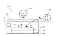
- FIG. 3 is an explanatory diagram showing another example of aerosol detection using the microchannel device 10.
- the same reference numbers as in FIG. 2 are used for components and the like.
- aerosols in the environment are sucked in and collected by the pump 38 in the same manner as in FIG. 2, a color reaction for detecting the aerosols is allowed to proceed, and the results are visually confirmed.
- the aerosols in the air are sucked in by the pump 38 and collected in the microwells 14, and the colorimetric reaction of the 5-Br-PAPS reagent filled in the microwells 14 is allowed to proceed.
- the zinc or cadmium can be detected by observer A visually checking the results of the colorimetric reaction using ambient light.
- FIG. 4 is an explanatory diagram showing yet another example of aerosol detection using the microchannel device 10.
- the same reference numbers as in FIG. 2 are used for components and the like.
- a light source 34 for illuminating the surface of the microchannel device 10 is attached to the side wall of the housing 32, and a color filter 46 is attached so as to cover the upper surface of the housing 32.
- the subject B blows his breath into the microchannel device 10 through the tube 42, and the aerosol particles to be detected (e.g., varicella zoster virus DNA) in the breath are collected.
- the aerosol particles to be detected e.g., varicella zoster virus DNA
- the microwell 14 is filled with an RPA reagent in advance, and the varicella zoster virus DNA is amplified and reacts with the fluorescent probe by heating it using the heater 40.
- the observer C visually confirms only the fluorescence through the color filter 46, allowing for diagnosis.
- aerosols are collected and detected in the microwells 14 that hold the detection liquid, eliminating the need to subject the collected aerosols to detection. By performing collection and detection simultaneously, the process from collection to detection can be expedited.
- the microwell 14 is formed as a microchannel together with the aerosol flow section 12, so that the amount of detection liquid used for detection can be reduced. By reducing the amount of detection liquid in this way, the cost required for aerosol detection can be reduced.
- the microfluidic device 10 of this embodiment detects aerosols using a detection liquid placed in the microwells 14, so as long as the detection method is liquid-based, various detection methods can be adopted as described above.
- the high degree of freedom in detection methods means that it can be used to detect various aerosols.
- the entire aerosol flow section 12 has a curved spiral shape, and microwells 14 are provided along the flow channel walls throughout the entire aerosol flow section 12. That is, the curved sections, which are shaped so that aerosol particles collide with the flow channel walls, and the microwells 14 that actually collect the aerosol are provided at a high density. Therefore, the entire aerosol flow section 12 can efficiently generate inertial forces and vortex flows, and collect the aerosols.
- the shape of the aerosol flow section 12 may be a shape other than a spiral shape.
- a curved section where the aerosol flow direction is changed may be formed only in a part of the aerosol flow section 12, where the aerosol particles in the aerosol collide with the flow path wall surface.
- it may be an arc shape with a single curved section, or a wave shape with alternating curved sections and straight sections.
- the flow path shape of the flow direction change section of the aerosol flow section 12 that changes the flow direction of the aerosol to generate inertial force, vortex flow, or turbulence may be a curved section, or a bent section where the flow path is bent at a specific angle, such as a right angle. In such a flow direction change section, by providing a microwell 14 on the flow path wall surface where the aerosol particles collide, the aerosol can be efficiently collected.
- FIG. 5 is a plan view showing a schematic configuration of the micro-channel device 110 of the second embodiment.
- the micro-channel device 110 of the second embodiment the same reference numerals are used for the parts common to the micro-channel device 10 of the first embodiment.
- the micro-channel device 110 further includes a humidifying section 26 for humidifying the aerosol flow section 12 in addition to the same structure as the micro-channel device 10.
- the humidifying section 26 of the second embodiment is a space formed in the micro-channel device 110, and is formed as a water storage section for holding water.
- the humidifying section 26 and the communicating flow section 16 are connected by a connecting flow section 28.
- the number of connecting flow sections 28 can be set arbitrarily, but in the second embodiment, a plurality of connecting flow sections 28 are provided along the direction in which the communicating flow section 16 extends.
- the microchannel device 110 has a structure that allows fluid to be supplied or discharged between the microchannels inside the microchannel device 110, and is provided with an aerosol inlet section 20, an aerosol outlet section 22, and a humidification opening section 24 as openings that open on the surface of the microchannel device 110.
- the humidification opening section 24 is provided at a position that overlaps with the humidification section 26.
- the air in the microchannel device 110 is degassed in a vacuum desiccator, and then detection liquid is supplied from the aerosol outlet 22 to the aerosol flow section 12, filling the area up to just before the communicating flow section 16 (near the boundary between the aerosol flow section 12 and the communicating flow section 16) with detection liquid.
- detection liquid is supplied to the aerosol flow section 12 after degassing the flow section including the microwells 14, the supplied detection liquid is introduced into each microwell 14. Thereafter, the detection liquid is sucked from the aerosol outlet 22 and removed from the aerosol flow section 12, allowing the detection liquid to be retained in the microwells 14.
- water is supplied to the humidifier section 26 through the humidifier opening 24 to fill the humidifier section 26 with water. If the water overflows into the communicating flow path 16 at this time, the water can be removed from the communicating flow path 16 by sucking it through the aerosol inlet section 20. In this way, the humidifier section 26 can be filled with water.
- the humidifier opening 24 is blocked when detecting aerosols.
- the humidifying section 26 has a relatively large cross-sectional area of the flow path, since it forms a space for storing water. Therefore, when water overflows from the humidifying section 26 into the communicating flow path 16 and it becomes necessary to remove the water from the communicating flow path 16 while leaving the water in the humidifying section 26, it is desirable to form the communicating flow path 16 with a larger cross-sectional area (the area of the cross section perpendicular to the direction of fluid flow in the flow path) than the connecting flow path 28 in order to perform the water removal operation smoothly, thereby increasing the relative flow path resistance of the connecting flow path 28.
- the communicating flow path 16 may be a flow path with a flow path diameter exceeding 1 mm, rather than a microflow path.
- the degree of evaporation of the detection liquid in the microwells 14 can vary depending on, for example, the temperature of the microchannel device 110 when detecting aerosols, the flow path diameter of the flow path in the microchannel device 110 through which the aerosol flows, the flow rate of the gas flowing through the microchannel device 110, and the like.
- microchannel device 110 it is possible to prevent evaporation of the detection liquid, so that the detection operation can be performed for a longer period of time and more stably, even when detecting aerosols under conditions where the detection liquid is likely to evaporate, such as when detecting aerosols at relatively high temperatures.
- the humidifier 26 is connected to the communicating channel 16 via the connecting channel 28 to humidify the aerosol prior to introduction into the aerosol flow section 12, thereby obtaining the effect of suppressing evaporation of the detection liquid in all microwells 14 provided along the aerosol flow section 12.
- the connection point of the humidifier 26 may be a different point other than the communicating channel 16, and may be connected, for example, midway through the aerosol flow section 12.
- the humidifier 26 has an overall periphery that is rectangular when viewed from above, and has a lattice-like flow channel shape due to the provision of a plurality of pillars 27 that are regularly arranged vertically and horizontally, but may have a different shape. For example, if the material that constitutes the microchannel device 110 is sufficiently strong, the pillars 27 may not be provided.
- water can be stored in the humidifier 26 before the aerosol collection and detection operations, so there is no need to supply water for humidification during the collection and detection operations, and the humidification operation can be simplified.
- a humidifier provided outside the microchannel device may be connected to the flow path within the microchannel device.
- the overall configuration of the aerosol detection apparatus including the microchannel device can be simplified and special control for humidification can be eliminated.
- FIG. 6 is an explanatory diagram showing a schematic configuration of a microchannel device 210 of the third embodiment in the same manner as FIG. 1A.
- the same reference numerals are used for the parts common to the microchannel device 10 of the first embodiment.
- the aerosol flow section 212 formed in the microchannel device 210 does not have a curved section like the aerosol flow section 12 of the first embodiment, and extends linearly from the aerosol inlet section 20 to the aerosol outlet section 22.
- the direction from the aerosol inlet section 20 to the aerosol outlet section 22 is referred to as the "aerosol flow direction".
- the aerosol flow direction In the aerosol flow section 212, as shown in FIG.
- large diameter sections 212a having a relatively large flow cross-sectional area and small diameter sections 212b having a relatively small flow cross-sectional area are alternately provided along the aerosol flow direction, and the flow cross-sectional area increases and decreases abruptly at the boundary between the two.
- the area including the area where the flow path cross-sectional area increases and decreases abruptly is the area having a shape where aerosol particles in the aerosol collide with the flow path wall surface.
- microwells 14 for holding detection liquid are provided at opposing positions on the flow path walls of the large diameter section 212a and the small diameter section 212b of the aerosol flow section 212.
- the aerosol inlet section 20 is provided at one end of the aerosol flow section in which the microwell 14 is formed, and the aerosol outlet section 22 is provided at the other end, but a different configuration may be used.
- the aerosol inlet sections may be provided at both ends of the aerosol flow section, and the aerosol outlet section 22 may be provided in the middle of the aerosol flow section.
- two types of aerosol collection and detection operations can be performed simultaneously by supplying aerosols sampled from different locations to each aerosol inlet section.
- the multiple microwells 14 are arranged in a regular pattern along the flow direction of the aerosol in the aerosol flow section 12 or the aerosol flow section 212, but a different configuration may be used.
- the multiple microwells 14 may be arranged randomly.
- the number of microwells 14 may be one, or any number greater than one can be set. If the microwells 14 are provided continuously on the wall surface in the aerosol flow section where the aerosol particles collide, the same effects as those of the above-mentioned embodiments can be obtained.
- a microchannel device having a configuration similar to that of the microchannel device 110 of the second embodiment shown in FIG. 5 and the microchannel device 210 of the third embodiment shown in FIG. 6 was fabricated, and the microwell 14 and the humidifying section 26 were filled with liquid.
- Each microchannel device was fabricated using polydimethylsiloxane (PDMS) as a material.
- PDMS polydimethylsiloxane
- the height of each channel was 500 ⁇ m
- the channel width of the aerosol flow section 12 was 500 ⁇ m
- the opening width of the microwell 14 was 500 ⁇ m
- the depth of the microwell 14 was 750 ⁇ m
- the channel width of the communicating channel 16 was 1.5 mm
- the channel width of the connecting channel 28 was 500 ⁇ m
- the channel length of the connecting channel 28 was 750 ⁇ m
- the outer circumference of the humidifying section 26 was 10 mm square
- the outer circumference of the column section 27 was 600 ⁇ m square.
- the height of each channel was 500 ⁇ m
- the channel width of the large diameter section 212a was 1 mm
- the channel length of the large diameter section 212a was 1 mm
- the channel width of the small diameter section 212b was 500 ⁇ m
- the channel length of the small diameter section 212b was 1 mm
- the opening width of the microwell 14 was 500 ⁇ m
- the depth of the microwell 14 was 500 ⁇ m.
- FIGS. 7A and 7B are explanatory diagrams showing the state in which the microchannel device 110 of the second embodiment shown in FIG. 5 has been fabricated and filled with liquid.
- FIG. 7A shows the state in which the entire microchannel in the microchannel device has been filled with ink liquid.
- FIG. 7B also shows the state in which the ink liquid has been sucked and removed from the aerosol flow section 12 and the communicating flow section 16 in the state shown in FIG. 7A using a pipette via the aerosol outlet section 22 and the aerosol inlet section 20. It was confirmed that by filling and removing the liquid as described above, it is possible to fill only the microwells 14 and the humidifier section 26 with the desired liquid and to allow gas to flow through the communicating flow section 16 and the aerosol flow section 12.
- FIG. 8 is an explanatory diagram showing the state in which the microchannel device 210 of the third embodiment shown in FIG. 6 has been produced and filled with liquid.
- FIG. 8 shows the state in which the ink liquid is filled into the entire flow channel in the microchannel device 210 by supplying ink liquid from the aerosol inlet portion 20 while discharging the ink liquid that has flowed through the aerosol flow portion 212 from the aerosol outlet portion 22, and then the ink liquid is sucked out and removed from the aerosol flow portion 212 using a pipette via the aerosol outlet portion 22. It was confirmed that by filling and removing the liquid as described above, it is possible to fill only the microwells 14 with the desired liquid and allow gas to flow through the aerosol flow portion 212.
- ⁇ Confirming the effectiveness of the humidifier> 9 is an explanatory diagram showing the results of investigating the effect of humidifying the aerosol flowing through the aerosol flow section 12 by the humidifying section 26 using the microchannel device 110 shown in FIG. 7A and FIG. 7B.
- the state in which the humidifying section 26 is filled with water is defined as "humidification enabled”
- the state in which the humidifying section 26 is empty is defined as “humidification disabled”.
- Air was circulated from the aerosol inlet section 20 to the aerosol outlet section 22 in a state in which the microwells 14 were filled with a solution, and the state in which the solution in the microwells 14 evaporated was observed.
- the air was circulated by connecting a pump (MP-60, AS ONE CORPORATION) to the aerosol outlet section 22 side via a mass flow controller (1SLM, FCON CORPORATION) and sucking air at a flow rate of 50 mL/min.
- a pump MP-60, AS ONE CORPORATION
- a mass flow controller (1SLM, FCON CORPORATION
- the change in the liquid volume in the microwell 14 was measured using image analysis software ImageJ. Specifically, the length from the bottom surface of the rectangular microwell 14 (the surface of the microwell 14 farthest from the interface with the aerosol outlet portion 22) to the gas-liquid interface in the microwell 14 (hereinafter also referred to as the "liquid level height") was measured every minute.
- the horizontal axis indicates the elapsed time from the start of the air flow.
- the vertical axis indicates the relative liquid level height when the liquid level height at the start of the air flow is set to 1. As shown in FIG.
- the operation of collecting fluorescent beads using the microchannel device 110 was carried out as follows. That is, in a sealed desiccator (LH, AS ONE Corporation), the solution containing the fluorescent beads was sprayed for 1 minute at a flow rate of 0.2 mL/min using a nebulizer (NE-C803, OMRON Healthcare Co., Ltd.). At the same time, a pump (MP-60, AS ONE Corporation) was connected to the aerosol outlet 22 of the microchannel device 110 in the desiccator, and air was sucked in at a pressure of -0.75 MPa for 5 minutes, and the sprayed fluorescent bead-containing solution was sucked from the aerosol inlet 20.
- a sealed desiccator LH, AS ONE Corporation
- a nebulizer NE-C803, OMRON Healthcare Co., Ltd.
- a pump MP-60, AS ONE Corporation
- the microwell 14 was filled with a 1.5% aqueous solution of sodium alginate (80-120, FUJIFILM Wako Pure Chemical Industries, Ltd.) gelled with a 150 mM solution of calcium chloride (special grade, FUJIFILM Wako Pure Chemical Industries, Ltd.).
- the microchannel device 110 was removed from the desiccator and observed using a fluorescence microscope (BIOREVO, Keyence Corporation).
- FIG. 10A is a bright-field image of a portion of the micro-channel device 110 including the micro-well 14, and FIG. 10B is a fluorescent image in the same field as FIG. 10A.
- FIG. 10B the fluorescent beads trapped at the gas-liquid interface between the aerosol flow section 12 and the micro-well 14 are indicated by white arrows.
- the fluorescent beads were observed to adhere to the gas-liquid interface of the micro-well 14. This is believed to be because the fluorescent beads were carried to the micro-well 14 by the inertial force of the fluorescent beads as they flowed through the spiral-shaped aerosol flow section 12, or by the secondary flow of the vortex flowing on the outer wall side of the flow channel. As described above, it was shown that even aerosol particles with a diameter of about 1 ⁇ m can be collected in the micro-well 14 using the micro-channel device 110.
- the operation of collecting fluorescent beads using the microchannel device 210 was performed as follows. That is, the solution containing the fluorescent beads was sprayed for 1 minute at a flow rate of 0.2 mL/min using a nebulizer (NE-C803, Omron Healthcare Co., Ltd.) in a sealed desiccator (VL, AS ONE Corporation). At the same time, a pump (MP-60, AS ONE Corporation) was connected to the aerosol outlet 22 of the microchannel device 210 in the desiccator via a mass flow controller (1SLM, FCON Corporation), and air was sucked in at a flow rate of 50 mL/min for 5 minutes, so that the sprayed fluorescent bead-containing solution was sucked from the aerosol inlet 20.
- a nebulizer NE-C803, Omron Healthcare Co., Ltd.
- VL sealed desiccator
- a pump MP-60, AS ONE Corporation
- a mass flow controller (1SLM, FCON Corporation
- the microwell 14 was filled with a 1.5% aqueous solution of sodium alginate (80-120, FUJIFILM Wako Pure Chemical Industries, Ltd.) gelled with a 150 mM solution of calcium chloride (special grade, FUJIFILM Wako Pure Chemical Industries, Ltd.).
- the microchannel device 210 was removed from the desiccator and observed using a fluorescence microscope (BIOREVO, Keyence Corporation).
- FIG. 11A is a bright-field image of a portion of the microchannel device 210 that includes the microwell 14, and FIG. 11B is a fluorescent image in the same field of view as FIG. 11A.
- FIG. 11B the fluorescent beads trapped at the gas-liquid interface between the aerosol flow section 12 and the microwell 14 are indicated by white arrows.
- the fluorescent beads were observed to adhere to the gas-liquid interface of the microwell 14. This is thought to be because the fluorescent beads were carried to the microwell 14 by turbulence caused by a sudden change in the flow channel width (cross-sectional area of the flow channel). As described above, it was shown that even aerosol particles with a diameter of about 1 ⁇ m can be collected in the microwell 14 using the microchannel device 210.
- plasmid DNA as an example of an aerosol, can be collected and detected by using the microfluidic device 110 shown in Figures 7A and 7B.
- a plasmid containing an EGFP gene which is a green fluorescent protein gene, was used as the plasmid DNA, and DNA was amplified in the microwell 14 by the RPA method.
- the collection and detection of plasmid DNA using the microchannel device 110 was performed as follows. That is, in a sealed desiccator (VL, AS ONE Corporation), a solution of a plasmid containing an EGFP sequence (concentration: 50 pg/mL) was sprayed for 5 minutes at a flow rate of 0.2 mL/min using a nebulizer (NE-C803, OMRON Healthcare Co., Ltd.).
- a pump (MP-60, AS ONE Corporation) was connected to the aerosol outlet 22 of the microchannel device 110 in the desiccator via a mass flow controller (1SLM, FCON Corporation) to suck air at a flow rate of 50 mL/min for 5 minutes, and the sprayed plasmid solution was aspirated from the aerosol inlet 20.
- the microwell 14 was filled in advance with an RPA solution (TwistAmp exo, TwistDx Co., Ltd.) containing a primer that specifically detects EGFP, an enzyme that performs a polymerase reaction, and a fluorescent probe that specifically binds to the amplification unit.
- a similar microchannel device 110 was used as a control, and a liquid not containing the plasmid was sprayed in the desiccator in the same manner and sucked into the microchannel device 110. After the above-mentioned 5 minutes of suction, the microchannel device 110 was removed from the desiccator and incubated at 40°C to carry out the DNA amplification reaction. Then, 20 minutes after the start of the amplification reaction, observation was carried out using a fluorescent microscope (BIOREVO, Keyence Corporation).
- Figure 12 is an explanatory diagram showing the results of measuring the brightness using a fluorescence microscope after 20 minutes of DNA amplification reaction.
- Figure 12 shows the results for n ⁇ 4 (n is the number of microwells 14 to be measured), and the error bars represent the standard deviation.
- Figure 13 is an image of the fluorescence brightness visually confirmed after 20 minutes of DNA amplification reaction. As shown in Figures 12 and 13, a significant difference occurred with the control at the time point of 20 minutes. This is thought to be because the plasmid recovered as aerosol was amplified by the RPA method in the microwells 14, causing the detection solution to emit fluorescence. This confirmed that selective detection of bioaerosols is possible using a microfluidic device equipped with microwells 14 that have the same collection and detection sections.
Landscapes
- Life Sciences & Earth Sciences (AREA)
- Health & Medical Sciences (AREA)
- General Health & Medical Sciences (AREA)
- Chemical & Material Sciences (AREA)
- Analytical Chemistry (AREA)
- Biochemistry (AREA)
- Physics & Mathematics (AREA)
- General Physics & Mathematics (AREA)
- Immunology (AREA)
- Pathology (AREA)
- Engineering & Computer Science (AREA)
- Biomedical Technology (AREA)
- Molecular Biology (AREA)
- Sampling And Sample Adjustment (AREA)
Abstract
エアロゾルの捕集・検出用マイクロ流路デバイスは、外部から流入したエアロゾルが流通し、エアロゾルが流れることによって発生する慣性力、渦流、および乱流のうちの少なくともいずれかにより、エアロゾル中のエアロゾル粒子が流路壁面に衝突する形状を有するマイクロ流路であるエアロゾル流通部と、エアロゾル流通部におけるエアロゾル粒子が衝突する壁面に連続して設けられ、エアロゾル粒子を検出するための検出液を内部に保持するための1つ以上のマイクロウェルと、を備える。
Description
本開示は、エアロゾルの捕集・検出用マイクロ流路デバイス、および、エアロゾルの捕集・検出方法に関する。
空気中には、感染症の原因となるウイルス等の病原体や各種の汚染物質の微粒子が、エアロゾルの状態で存在し得る。そのため、空気中のエアロゾルを捕集してエアロゾル粒子を検出することにより、例えばエアロゾル粒子が病原体の場合には感染の予測や防止に役立てることが可能になり、またエアロゾル粒子が汚染物質の場合には、空気の汚染状態を把握することが可能になる。従来、エアロゾルを捕集して検出する種々の方法が提案されている。例えば、特許文献1では、エアロゾル物質などの脅威物質を基材に付着させて、複数の光子で照明し、発生した弾性散乱光子およびラマン散乱光子を分析して、脅威物質の基材への付着と同時に試料を分析・識別する方法を開示している。また、非特許文献1では、慣性衝突システムを用いて空中浮遊病原微生物を衝突プレートに衝突させ、蛍光顕微鏡画像を得ることによって、リアルタイムで非生物粒子とエアロゾル化生物粒子とを識別する技術を開示している。
特許文献2では、呼気中の粒子を捕集して測定する方法であって、固体表面(インパクタの捕集プレートの表面)にエアロゾルを捕集した後に捕集プレートを回収して、捕集した粒子の測定に供する方法が開示されている。また、特許文献3および特許文献4では生物学的物質検出システムが記載されており、このような特許文献3および特許文献4や、さらに非特許文献2では、収集装置を用いて捕集したエアロゾルを液体中に移して回収する方法が開示されている。また、非特許文献3および非特許文献4では、エアロゾルの検出のための液系捕集方法であって、エアロゾルと収集液体の二相流体を流路に流して粒子を気相から液相に移動させる方法が開示されている。
Joon Sang Kang et al., Real-time detection of an airborne microorganism using inertial impaction and mini-fluorescent microscopy, Lab Chip 14, 244-251(2014)
Jing W. et al., Microfluidic Device for Efficient Airborne Bacteria Capture and Enrichment, Amal. Chem. 85, 5255-5262(2013)
Choi J. et al., Highly Enriched, Controllable, Continuous Aerosol Sampling Using Inertial Microfluidics and Its Application to Real-Time Detection of Airborne Bacteria, ACS Sensors 2, 513-521(2017)
Heo K. J. et al., Enriched Aerosol-to-Hydrosol Transfer for Rapid and Continuous Monitoring of Bioaerosols, Nano Lett. 21, 1017-1024(2021)
しかしながら、特許文献1では、基材に付着された脅威物質の識別の際に弾性散乱とラマン散乱とを組み合わせる方法を採用しており、検出方法の自由度が制限されている。また、非特許文献1では、蛍光顕微鏡画像を用いて非生物粒子と生物粒子を識別している。そのため、このような固体表面でエアロゾルを捕集してリアルタイムで検出する方法では、雑多なサンプルの中に特定のエアロゾル粒子が含まれることを同定することが困難であった。
また、特許文献2~4や非特許文献2に記載の方法のように、収集装置を用いて捕集したエアロゾルを回収して検出に供する方法では、捕集と検出との間にラグタイムが生じるという問題があった。さらに、非特許文献3および非特許文献4のように、エアロゾルの捕集のためにエアロゾルと収集液体の二相流体を流路に流す場合には、捕集のための液を供給し続ける必要があり、液の供給に係る装置構成が複雑化し、捕集のために多量の液が必要になるという問題があった。そのため、装置構成や検出に係る動作の複雑化や、エアロゾルの捕集と検出との間のラグタイムを抑えつつ、検出方法の自由度が高い技術が望まれていた。
本開示は、以下の形態として実現することが可能である。
(1)本開示の一形態によれば、エアロゾルの捕集・検出用マイクロ流路デバイスが提供される。このエアロゾルの捕集・検出用マイクロ流路デバイスは、外部から流入したエアロゾルが流通し、エアロゾルが流れることによって発生する慣性力、渦流、および乱流のうちの少なくともいずれかにより、前記エアロゾル中のエアロゾル粒子が流路壁面に衝突する形状を有するマイクロ流路であるエアロゾル流通部と、前記エアロゾル流通部における前記エアロゾル粒子が衝突する壁面に連続して設けられ、前記エアロゾル粒子を検出するための検出液を内部に保持するための1つ以上のマイクロウェルと、を備える。
この形態のマイクロ流路デバイスによれば、検出液を保持したマイクロウェルにおいてエアロゾルの捕集と検出とを行うことができるため、捕集したエアロゾルを検出に供する動作などが不要になり、捕集から検出までの動作の迅速化が可能になる。また、マイクロ流路デバイスにおいて、エアロゾルの捕集の動作に先立ってマイクロウェル内に検出液を配置しておけばよく、捕集の動作の開始後に検出液を供給する必要がないため、検出液の供給に係る構成を簡素化し、必要な検出液の量を抑えることができる。さらに、エアロゾル流通部と共にマイクロウェルがマイクロ流路として形成されているため、検出のために用いる検出液の量を抑えて、エアロゾルの検出に要するコストを抑えることができる。また、マイクロウェル内に配置した検出液を用いてエアロゾルの検出を行うため、液系の検出方法であれば種々の検出方法を採用可能となり、検出方法の自由度を高めて種々のエアロゾルの検出に用いることができる。
(2)上記形態のエアロゾルの捕集・検出用マイクロ流路デバイスにおいて、前記エアロゾル流通部は、前記エアロゾル中のエアロゾル粒子が流路壁面に衝突する前記形状を有する部位として、流路形状が湾曲した湾曲部を備えることとしてもよい。このような構成とすれば、エアロゾル流通部の形状を、湾曲部を備える形状にするという簡素な構成により、エアロゾルが慣性力や渦流によって流路壁面に衝突し、エアロゾルをマイクロウェルに捕集する動作を効率よく行うことができる。
(3)上記形態のエアロゾルの捕集・検出用マイクロ流路デバイスにおいて、前記エアロゾル流通部は、流路形状が渦巻き形状である前記湾曲部を備えることとしてもよい。このような構成とすれば、エアロゾル粒子が流路壁面に衝突する形状である湾曲部が高い密度で配置されるため、エアロゾルの捕集効率を高めることができる。
(4)上記形態のエアロゾルの捕集・検出用マイクロ流路デバイスにおいて、前記エアロゾル流通部を加湿する加湿部をさらに備えることとしてもよい。このような構成とすれば、エアロゾルの検出を行う際に、マイクロウェル内の検出液が蒸発して減少することを抑えることができる。そのため、より長く安定して検出の動作を行うことができる。
(5)上記形態のエアロゾルの捕集・検出用マイクロ流路デバイスにおいて、前記加湿部は、前記エアロゾル流通部に連通して設けられて水を保持する貯水部であることとしてもよい。このような構成とすれば、エアロゾルの捕集および検出の動作に先立って予め加湿部に水を蓄えておけばよいため、加湿のための動作を簡素化することができる。
(6)上記形態のエアロゾルの捕集・検出用マイクロ流路デバイスにおいて、さらに、外部から前記マイクロ流路デバイス内へとエアロゾルが流入するエアロゾル流入部と、該エアロゾル流入部と前記エアロゾル流通部とを連通する連通流路と、を備え、前記貯水部は、前記連通流路に連通して設けられていることとしてもよい。このような構成とすれば、エアロゾル流通部よりも上流の連通流路に連通して加湿部を設けることにより、エアロゾル流通部の壁面に連続して設けられたすべてのマイクロウェルにおいて、検出液の蒸発を抑えることができる。
(7)上記形態のエアロゾルの捕集・検出用マイクロ流路デバイスにおいて、さらに、前記連通流路と前記貯水部とを接続する接続流路を備え、前記連通流路は、前記接続流路よりも流路断面積が大きく形成されていることとしてもよい。このような構成とすれば、連通流路と貯水部とを合わせた空間に水を導入した後に連通流路から水を除去することによって、貯水部に水を保持させる場合に、貯水部に水を残しつつ連通流路から水を除去する操作が容易になる。
(8)本開示の他の一形態によれば、エアロゾルの捕集・検出方法が提供される。このエアロゾルの捕集・検出方法は、(1)から(7)までのいずれか一項に記載のエアロゾルの捕集・検出用マイクロ流路デバイスを用いて、前記マイクロウェル内に前記検出液を満たし、前記エアロゾル流通部におけるエアロゾルの流れ方向の上流側端部と下流側端部との間で圧力差を生じさせることにより、前記エアロゾル流通部においてエアロゾルを流通させて、前記エアロゾル流通部を流れるエアロゾル中のエアロゾル粒子を前記マイクロウェル内の前記検出液中に捕集し、前記マイクロウェル内の前記エアロゾル粒子を検出する。
この形態のエアロゾルの捕集・検出方法によれば、検出液を保持したマイクロウェルにおいてエアロゾルの捕集と検出とを行うことができるため、捕集したエアロゾルを検出に供する動作などが不要になり、捕集から検出までの動作の迅速化が可能になる。また、エアロゾルの捕集の動作に先立ってマイクロウェル内に検出液を配置するため、捕集の動作の開始後に検出液を供給する必要がなく、検出液の供給に係る構成を簡素化し、必要な検出液の量を抑えることができる。さらに、エアロゾル流通部と共にマイクロウェルがマイクロ流路として形成されたマイクロ流路デバイスを用いるため、検出のために用いる検出液の量を抑えて、エアロゾルの検出に要するコストを抑えることができる。また、マイクロウェル内に配置した検出液を用いてエアロゾルの検出を行うため、液系の検出方法であれば種々の検出方法を採用可能となり、検出方法の自由度を高めて種々のエアロゾルの検出に用いることができる。
本開示は、上記以外の種々の形態で実現可能であり、例えば、エアロゾルの捕集・検出用マイクロ流路デバイスの使用方法や、エアロゾルの捕集・検出用マイクロ流路デバイスを備えるエアロゾル検出装置などの形態で実現することが可能である。
(1)本開示の一形態によれば、エアロゾルの捕集・検出用マイクロ流路デバイスが提供される。このエアロゾルの捕集・検出用マイクロ流路デバイスは、外部から流入したエアロゾルが流通し、エアロゾルが流れることによって発生する慣性力、渦流、および乱流のうちの少なくともいずれかにより、前記エアロゾル中のエアロゾル粒子が流路壁面に衝突する形状を有するマイクロ流路であるエアロゾル流通部と、前記エアロゾル流通部における前記エアロゾル粒子が衝突する壁面に連続して設けられ、前記エアロゾル粒子を検出するための検出液を内部に保持するための1つ以上のマイクロウェルと、を備える。
この形態のマイクロ流路デバイスによれば、検出液を保持したマイクロウェルにおいてエアロゾルの捕集と検出とを行うことができるため、捕集したエアロゾルを検出に供する動作などが不要になり、捕集から検出までの動作の迅速化が可能になる。また、マイクロ流路デバイスにおいて、エアロゾルの捕集の動作に先立ってマイクロウェル内に検出液を配置しておけばよく、捕集の動作の開始後に検出液を供給する必要がないため、検出液の供給に係る構成を簡素化し、必要な検出液の量を抑えることができる。さらに、エアロゾル流通部と共にマイクロウェルがマイクロ流路として形成されているため、検出のために用いる検出液の量を抑えて、エアロゾルの検出に要するコストを抑えることができる。また、マイクロウェル内に配置した検出液を用いてエアロゾルの検出を行うため、液系の検出方法であれば種々の検出方法を採用可能となり、検出方法の自由度を高めて種々のエアロゾルの検出に用いることができる。
(2)上記形態のエアロゾルの捕集・検出用マイクロ流路デバイスにおいて、前記エアロゾル流通部は、前記エアロゾル中のエアロゾル粒子が流路壁面に衝突する前記形状を有する部位として、流路形状が湾曲した湾曲部を備えることとしてもよい。このような構成とすれば、エアロゾル流通部の形状を、湾曲部を備える形状にするという簡素な構成により、エアロゾルが慣性力や渦流によって流路壁面に衝突し、エアロゾルをマイクロウェルに捕集する動作を効率よく行うことができる。
(3)上記形態のエアロゾルの捕集・検出用マイクロ流路デバイスにおいて、前記エアロゾル流通部は、流路形状が渦巻き形状である前記湾曲部を備えることとしてもよい。このような構成とすれば、エアロゾル粒子が流路壁面に衝突する形状である湾曲部が高い密度で配置されるため、エアロゾルの捕集効率を高めることができる。
(4)上記形態のエアロゾルの捕集・検出用マイクロ流路デバイスにおいて、前記エアロゾル流通部を加湿する加湿部をさらに備えることとしてもよい。このような構成とすれば、エアロゾルの検出を行う際に、マイクロウェル内の検出液が蒸発して減少することを抑えることができる。そのため、より長く安定して検出の動作を行うことができる。
(5)上記形態のエアロゾルの捕集・検出用マイクロ流路デバイスにおいて、前記加湿部は、前記エアロゾル流通部に連通して設けられて水を保持する貯水部であることとしてもよい。このような構成とすれば、エアロゾルの捕集および検出の動作に先立って予め加湿部に水を蓄えておけばよいため、加湿のための動作を簡素化することができる。
(6)上記形態のエアロゾルの捕集・検出用マイクロ流路デバイスにおいて、さらに、外部から前記マイクロ流路デバイス内へとエアロゾルが流入するエアロゾル流入部と、該エアロゾル流入部と前記エアロゾル流通部とを連通する連通流路と、を備え、前記貯水部は、前記連通流路に連通して設けられていることとしてもよい。このような構成とすれば、エアロゾル流通部よりも上流の連通流路に連通して加湿部を設けることにより、エアロゾル流通部の壁面に連続して設けられたすべてのマイクロウェルにおいて、検出液の蒸発を抑えることができる。
(7)上記形態のエアロゾルの捕集・検出用マイクロ流路デバイスにおいて、さらに、前記連通流路と前記貯水部とを接続する接続流路を備え、前記連通流路は、前記接続流路よりも流路断面積が大きく形成されていることとしてもよい。このような構成とすれば、連通流路と貯水部とを合わせた空間に水を導入した後に連通流路から水を除去することによって、貯水部に水を保持させる場合に、貯水部に水を残しつつ連通流路から水を除去する操作が容易になる。
(8)本開示の他の一形態によれば、エアロゾルの捕集・検出方法が提供される。このエアロゾルの捕集・検出方法は、(1)から(7)までのいずれか一項に記載のエアロゾルの捕集・検出用マイクロ流路デバイスを用いて、前記マイクロウェル内に前記検出液を満たし、前記エアロゾル流通部におけるエアロゾルの流れ方向の上流側端部と下流側端部との間で圧力差を生じさせることにより、前記エアロゾル流通部においてエアロゾルを流通させて、前記エアロゾル流通部を流れるエアロゾル中のエアロゾル粒子を前記マイクロウェル内の前記検出液中に捕集し、前記マイクロウェル内の前記エアロゾル粒子を検出する。
この形態のエアロゾルの捕集・検出方法によれば、検出液を保持したマイクロウェルにおいてエアロゾルの捕集と検出とを行うことができるため、捕集したエアロゾルを検出に供する動作などが不要になり、捕集から検出までの動作の迅速化が可能になる。また、エアロゾルの捕集の動作に先立ってマイクロウェル内に検出液を配置するため、捕集の動作の開始後に検出液を供給する必要がなく、検出液の供給に係る構成を簡素化し、必要な検出液の量を抑えることができる。さらに、エアロゾル流通部と共にマイクロウェルがマイクロ流路として形成されたマイクロ流路デバイスを用いるため、検出のために用いる検出液の量を抑えて、エアロゾルの検出に要するコストを抑えることができる。また、マイクロウェル内に配置した検出液を用いてエアロゾルの検出を行うため、液系の検出方法であれば種々の検出方法を採用可能となり、検出方法の自由度を高めて種々のエアロゾルの検出に用いることができる。
本開示は、上記以外の種々の形態で実現可能であり、例えば、エアロゾルの捕集・検出用マイクロ流路デバイスの使用方法や、エアロゾルの捕集・検出用マイクロ流路デバイスを備えるエアロゾル検出装置などの形態で実現することが可能である。
A.第1実施形態:
図1Aおよび図1Bは、本開示の第1実施形態としてのマイクロ流路デバイス10の概略構成を表す説明図である。図1Aは平面図を表し、図1Bは、図1AにおけるB-B断面の様子を表す断面図である。なお、図1Aおよび図1Bは、各部の寸法の比率を正確に表すものではない。
図1Aおよび図1Bは、本開示の第1実施形態としてのマイクロ流路デバイス10の概略構成を表す説明図である。図1Aは平面図を表し、図1Bは、図1AにおけるB-B断面の様子を表す断面図である。なお、図1Aおよび図1Bは、各部の寸法の比率を正確に表すものではない。
本実施形態のマイクロ流路デバイス10は、内部にマイクロ流路が形成された板状部材であり、外部からマイクロ流路へと取り込んだエアロゾルを捕集して検出するためのデバイスである。マイクロ流路デバイス10は、エアロゾル流通部12と、マイクロウェル14と、エアロゾル流入部20と、連通流路16と、エアロゾル流出部22と、を備える。
エアロゾル流通部12は、外部から流入したエアロゾルが流通するマイクロ流路である。エアロゾル流通部12は、エアロゾルが流れることによって発生する慣性力、渦流、および乱流のうちの少なくともいずれかにより、エアロゾル中のエアロゾル粒子が流路壁面に衝突する形状を有している。本実施形態のエアロゾル流通部12は、流路形状が湾曲した湾曲部を備えており、エアロゾル流通部12を流れるエアロゾルが、慣性力および渦流によって湾曲部の流路壁面に衝突する。より具体的には、エアロゾル流通部12は、流路形状が渦巻き形状である湾曲部を備える。
マイクロウェル14は、エアロゾル流通部12におけるエアロゾル粒子が衝突する壁面に連続して設けられており、エアロゾル粒子を検出するための検出液を内部に保持するための構造である。すなわち、エアロゾル流通部12におけるエアロゾルが衝突する壁面と、マイクロウェル14の壁面とが連続しており、エアロゾル流通部12を構成する流路と、マイクロウェル14内の空間とが連通している。本実施形態では、渦巻き形状のエアロゾル流通部12の外周側の壁面に沿って、複数のマイクロウェル14が、上記外周側の壁面からさらに外側に延びるように突出した形状で設けられている。図1Aでは、マイクロ流路デバイス10の全体構成を示すと共に、マイクロウェル14が設けられたエアロゾル流通部12の一部を拡大して示している。また、図1Aでは、マイクロウェル14内に検出液が保持される様子を、マイクロウェル14にハッチングを付して示している。図1Aに拡大して示すように、エアロゾル流通部12を流れるエアロゾルでは、エアロゾル流通部12が渦巻き形状であることによって慣性力や渦流が生じ、エアロゾル中のエアロゾル粒子Aspが流路壁面に衝突する。このとき、流路壁面に連続してマイクロウェル14が設けられている箇所では、エアロゾル粒子Aspはマイクロウェル14内に侵入して、マイクロウェル14内に保持される検出液中に捕集される。その後、検出液とエアロゾル粒子Aspとが反応し、このような反応の結果としての状態を検出することにより、エアロゾルが検出される。エアロゾルの検出については、後に詳しく説明する。
エアロゾル流入部20は、マイクロ流路デバイス10内に外部からエアロゾルを導入するための構造であり、マイクロ流路デバイス10の表面で開口する開口部である。連通流路16は、エアロゾル流入部20とエアロゾル流通部12とを連通させるマイクロ流路である。本実施形態では、連通流路16は、渦巻き形状に形成されたエアロゾル流通部12の外側端部とエアロゾル流入部20とを接続するように、直線状の流路として形成しているが、連通流路16は直線状とは異なる形状としてもよい。また、連通流路16を設けることなく、渦巻き形状のエアロゾル流通部12の端部にエアロゾル流入部20を設けることとしてもよい。
エアロゾル流出部22は、マイクロ流路デバイス10内を通過したエアロゾルをマイクロ流路デバイス10の外部に排出するための構造であり、渦巻き形状に形成されたエアロゾル流通部12の内側端部に連通して、マイクロ流路デバイス10の表面で開口する開口部である。マイクロ流路デバイス10の使用時には、エアロゾル流通部12におけるエアロゾルの流れ方向の上流側端部と下流側端部との間で、すなわち、エアロゾル流入部20とエアロゾル流出部22との間で、圧力差を生じさせる。これにより、エアロゾル流入部20側からエアロゾル流出部22側に向かってエアロゾル流通部12内でエアロゾルを流通させることができる。
エアロゾル流入部20とエアロゾル流出部22との間で圧力差を生じさせる方法は、特に限定されず、種々の方法を採用可能である。例えば、エアロゾル流出部22にポンプを接続してエアロゾル流出部22側で吸引力を発生させる方法が挙げられる。このとき、例えばエアロゾル流入部20を大気開放してポンプを駆動すれば、大気中のエアロゾルをエアロゾル流通部12に導入することができる。あるいは、検出対象であるエアロゾルを封入したシリンジをエアロゾル流入部20側に接続して、シリンジによってエアロゾルを押し込むことによってエアロゾル流通部12にエアロゾルを導入してもよい。あるいは、呼気中のエアロゾルを検出する場合には、エアロゾル流入部20に接続したチューブに対して呼気を吹き込むこととしてもよい。
エアロゾル流通部12、マイクロウェル14、連通流路16などのマイクロ流路は、流路の大きさである流路高さや流路幅、あるいは、流路断面積と同等の面積を有する円の直径としての流路径が、1μm以上1mm以下となるように形成すればよい。エアロゾルが流れる際の流路抵抗を適切化する観点から、エアロゾル流通部12の流路径は、100μm以上とすることが望ましい。マイクロウェル14において、エアロゾル流通部12の外壁面から外側に突出して伸びる方向に垂直な面の流路径は、エアロゾル流通部12の流路径と同等以下であることが望ましい。検出液を導入してエアロゾル流通部12およびマイクロウェル14を検出液で満たした後に、エアロゾル流通部12から検出液を抜き取ることによって、マイクロウェル14内に検出液を保持させる場合に、マイクロウェル14内に検出液を残しつつエアロゾル流通部12から検出液を抜き取る動作が容易になるためである。
マイクロ流路デバイス10の構成材料は、マイクロ流路を形成可能な加工性を有していればよい。また、マイクロ流路デバイス10を用いた検出方法として例えば光学的な方法を採用する場合には、マイクロ流路デバイス10の構成材料は、マイクロウェル14内の検出液に捕集された状態でエアロゾルを検出可能になる透明性や透光性を有していればよい。ただし、マイクロ流路デバイス10を用いた検出方法としては、電気化学的方法など種々の方法を採用可能であるため、マイクロ流路デバイス10の構成材料における透明性や透光性は必須ではない。マイクロ流路デバイス10の構成材料としては、例えば、ポリジメチルシロキサン(PDMS)等のシリコーン樹脂、シクロオレフィン樹脂、アクリル樹脂、あるいはガラスなどを挙げることができる。
図1Bは、マイクロ流路デバイス10の構成の一例として、上記した材料によって構成される板状部材を積層した3層構造を示している。ここでは、マイクロ流路デバイス10は、板状部材10a~10cをこの順で積層することによって構成されている。板状部材10bには、図1Aにおいてエアロゾル流通部12、マイクロウェル14、および連通流路16として示した形状の貫通孔が形成されている。板状部材10aには、エアロゾル流入部20およびエアロゾル流出部22となる貫通孔が形成されている(ただし、図1Bでは、エアロゾル流入部20のみを示している)。板状部材10cは、貫通孔を有していない。このような板状部材10a~10cを積層して接合することにより、マイクロ流路デバイス10を作製することができる。あるいは、マイクロ流路デバイス10は、2枚の板状部材を積層して形成することとしてもよい、この場合には、例えば、一方の板状部材の表面に、エアロゾル流通部12やマイクロウェル14や連通流路16となる凹部を形成すると共に、いずれかの板状部材に、エアロゾル流入部20およびエアロゾル流出部22となる貫通孔を形成すればよい。そして、このような板状部材における凹部を形成した側の面と、他方の板状部材とを接合すればよい。あるいは、2枚の板状部材の対向する面の各々に、エアロゾル流通部12やマイクロウェル14や連通流路16となる凹部を形成し、両者を接合してもよい。
マイクロ流路デバイス10を用いて検出する検出対象のエアロゾルとしては、例えば、エアロゾル粒子として直径100μm以下の細菌、真菌、花粉、ウイルス、細胞、DNA、RNAなどを含むバイオエアロゾルや、金属エアロゾルや、排ガスエアロゾルとすることができる。
検出液の種類は、検出したいエアロゾルの種類に応じて選択すればよく、選択した検出液とエアロゾルとの組み合わせにより、検出液とエアロゾル粒子との間で、エアロゾルを検出可能となる特定の反応が進行すればよい。本実施形態のマイクロ流路デバイス10では、エアロゾルの検出の動作の途中でマイクロウェル14に対して検出液を追加することや、検出液を入れ替えることは予定していない。そのため、用いる検出液は、予めマイクロウェル14内に配置しておくことで、マイクロウェル14で捕集したエアロゾルを検出するための反応(検出までに複数段階の反応が進行する場合にはすべての反応)が進行可能になる検出液であればよい。
エアロゾルの検出のために検出液とエアロゾルとの間で進行する反応は、例えば、化学発光あるいは生物発光を生じる反応や、蛍光により検出可能になる反応や、呈色反応を伴う反応など、種々の反応を採用することができる。このような、エアロゾルと検出液との間で進行する反応に応じて、進行する反応の程度を検出できるように、検出方法を適宜選択すればよい。発光や呈色反応を検出する場合には、例えば、目視による検出の他、カメラやフォトダイオードや光電子増倍管等の機器を用いた検出を行うことができる。このような検出の際には、必要に応じて、検出のための光源として、自然光、環境光、LEDライト、レーザー、白熱灯、水銀ランプ、キセノンランプ等を適宜選択して用いればよい。また、検出液とエアロゾルとの間で進行する反応は、発光や発色を伴う反応の他、例えば電流値の変化等を伴う電気的な反応を含んでいてもよい。
エアロゾルと検出液との間で進行する反応の具体例を以下に説明する。検出対象のエアロゾル粒子が細菌、真菌、細胞など(以下、細菌等とも呼ぶ)の場合には、例えば、生物発光を利用したATPアッセイ(ATP法)を適用することができる。細胞由来のATP量と細胞数との間には相関があることが知られており、ATPは、マグネシウムイオン(Mg2+)存在下でホタルルシフェリン・ルシフェラーゼ試薬との反応により発光する。ATP法は、上記原理を利用した周知の方法である。そのため、ルシフェリンおよびルシフェラーゼを含むATP検出用試薬を検出液として用いてATP量を測定することで、エアロゾル粒子としての細菌等を検出することができる。上記発光の検出には、例えばカメラを用いればよい。
また、検出対象のエアロゾル粒子が細菌等の場合には、BactoLumix法を適用することとしてもよい。BactoLumix法は、細菌等が持っている酵素であるNAD(P)H(キノン酸化還元酵素)とメナジオンとの酸化還元反応で発生した活性酸素を、発光基質を添加して検出する方法であり、生菌数に比例した発光量を測定可能になる周知の方法である。そのため、上記BactoLumix法用のメナジオンおよび発光基質を含む試薬を検出液として用いてNAD(P)Hを測定することで、エアロゾル粒子としての細菌等を検出することができる。上記発光の検出には、例えばカメラを用いればよい。
また、検出対象のエアロゾル粒子が細胞の場合には、Calcein-AMやフルオレセインジアセテート誘導体を含む種々の蛍光性エステラーゼ基質を用いることも可能である。上記蛍光性エステラーゼ基質は、細胞内に入ると細胞内エステラーゼにより加水分解されて蛍光シグナルを発生する。そのため、上記蛍光性エステラーゼ基質を含む検出液を用いて蛍光を測定することで、エアロゾル粒子としての細胞を検出することができる。上記蛍光の検出には、例えば蛍光顕微鏡を用いればよい。
また、検出対象のエアロゾル粒子が、細菌、真菌、花粉、ウイルス、細胞等であって、抗体が得られている場合には、電気化学測定を利用することもできる。上記検出対象の抗体を、マイクロウェル14に組み込まれた電極に固定するならば、マイクロウェル14内の検出液に検出対象のエアロゾル粒子が捕集されて上記抗体に結合したときに、電極と電解液の間の電荷のやり取りが変化することで抵抗や電流値が変化するため、このような変化を検出することにより、上記所望の検出対象を検出することができる。
また、検出対象のエアロゾル粒子がDNAやRNA等の核酸の場合や、検出対象のエアロゾル粒子がウイルスあるいは細菌等であって、当該ウイルスあるいは細菌等が含む核酸を検出することによってエアロゾル粒子を検出する場合には、核酸染色用の試薬を含む検出液を用いればよい。核酸染色用の試薬としては、例えば、SYBR GreenIやエチジウムブロマイドを用いることができる。染色結果の検出には、例えばカメラを用いればよい。
検出対象のエアロゾル粒子が、DNAやRNA等の核酸である場合や、検出対象のエアロゾル粒子がウイルスあるいは細菌等であって、当該ウイルスあるいは細菌等が含む核酸を検出することによってエアロゾル粒子を検出する場合には、マイクロウェル14内の検出液において核酸を増幅することが望ましい。検出液中で核酸を増幅させる方法としては、例えば、LAMP(Loop-Mediated Isothermal Amplification)法、PCR(Polymerase Chain Reaction)法、RPA法(Recombinase Polymerase Amplification)法を挙げることができる。これらの中でも、LAMP法およびRPA法は、一定温度で増幅反応を進行させることができるため、望ましい。また、LAMP法は、増幅反応の進行の検出が比較的容易である点で望ましい。
検出対象の核酸に応じて設計したプライマーを含有するLAMP試薬を検出液として用い、検出液中で核酸の増幅を行った場合には、検出液中にピロリン酸マグネシウムが生成されることにより検出液が白濁するため、濁度を光学的に測定することや、白濁した様子を目視により確認することにより、エアロゾル粒子の検出を行うことができる。また、核酸増幅にLAMP法を用いる場合には、検出液にカルセインやヒドロキシナフトールブルーなどの指示薬を添加することで、核酸の増幅を色の変化(呈色反応)として検出することができる。呈色反応は、例えば、カメラの使用や目視により検出することができる。また、核酸増幅にRPA法を用いる場合には、蛍光プローブを使用して、例えばカメラや目視により蛍光を検出することができる。
検出対象のエアロゾルが金属エアロゾルの場合には、特定の金属イオンと反応して呈色する比色試薬である金属指示薬を含む検出液を用いて、検出液中でイオン化した金属を検出すればよい。例えば、比色試薬である5-Br-PAPSを含む検出液を用いる場合には、亜鉛イオンの他、カドミウムイオン、鉄イオン、ニッケルイオン、コバルトイオン等を検出することができる。上記呈色反応の検出は、例えば目視やカメラを用いて行えばよい。
検出対象のエアロゾルが排ガスエアロゾルの場合には、エアロゾル中の検出したい粒子、あるいは、エアロゾル中の検出したい成分に応じて、適宜、検出液を選択すればよい。例えば、液中で硫酸イオンを生じる硫黄酸化物を検出対象にする場合には、バリウムを含む試薬を検出液として用いて硫酸バリウムの沈殿を生じさせて濁度を測定する方法(硫酸バリウム比濁法)により、排ガス中の硫黄酸化物を検出することができる。この場合には、上記バリウムを含む試薬は、安定化剤としてさらにポリエチレングリコール(PEG)やグリセリンを含んでいてもよい。濁度は、例えばレーザー強度により確認することができる。
図2は、マイクロ流路デバイス10を備えるエアロゾル検出装置の一例としての装置30の概略構成を示す説明図である。装置30は、筐体32内にマイクロ流路デバイス10を収納しており、筐体32内には、さらに、マイクロ流路デバイス10の表面を照明する光源34と、エアロゾル検出のためにマイクロ流路デバイス10のマイクロウェル14を上方から撮像するカメラ36と、ポンプ38と、ヒータ40と、が配置されている。マイクロ流路デバイス10のエアロゾル流入部20には、一端が筐体32外で大気開放されたチューブ42の他端が接続されている。また、マイクロ流路デバイス10のエアロゾル流出部22には、一端がポンプ38に接続されたチューブ44の他端が接続されている。そのため、ポンプ38を駆動することにより、エアロゾルを含む外気を、エアロゾル流入部20を介してエアロゾル流通部12へと取り込み、マイクロウェル14内の検出液中にエアロゾルを捕集して検出のための反応を進行させ、カメラ36を用いてエアロゾルの検出を行うことができる。
図2に示すように、マイクロ流路デバイス10を加熱するためのヒータ40を設ける場合には、室温よりも高い所望の温度にて、検出のための反応を進行させることができる。例えば、核酸を検出対象として、LAMP法やRPA法により核酸の増幅を行う場合には、増幅に適した温度になるように、ヒータ40を用いた加熱を行えばよい。また、PCR法により核酸の増幅を行う場合には、ヒータ40に加えてさらに冷却装置を設けて、予め設定したパターンにて温度の上昇および低下が行われるように制御すればよい。また、ウイルスを検出対象として、検出液において捕集したウイルスから核酸を抽出する場合には、核酸抽出の工程において核酸抽出に適した温度になるように、ヒータ40を用いてマイクロ流路デバイス10を加熱すればよい。
図2の装置30を用いた例では、環境中のエアロゾルをポンプ38により吸引して捕集し、エアロゾルを検出するための加熱による呈色反応を進行させて、カメラ36を用いて結果を確認する。具体的には、例えば、病院内の空気中に浮遊するウイルスを検出対象とする場合には、上記空気中のエアロゾルをポンプ38により吸引してマイクロウェル14に捕集し、ヒータ40を用いた加熱によってウイルスからRNAを抽出する。このとき、予めマイクロウェル14内に、RT-LAMP試薬とナフトールブルー試薬とを含む液を満たしておけば、ヒータ40によって反応温度を変えて検出対象のDNAを増幅することでナフトールブルー試薬が反応し、呈色反応をカメラ36により検出することができる。
図3は、マイクロ流路デバイス10を用いてエアロゾル検出を行う他の例を示す説明図である。図3において、図2と共通する部材等には図2と同じ参照番号を付す。ここでは、図2と同様にして環境中のエアロゾルをポンプ38により吸引して捕集し、エアロゾルを検出するための呈色反応を進行させて、目視により結果を確認する。具体的には、例えば、亜鉛精錬工場の空気中に含まれる亜鉛またはカドミウムの浮遊粒子を検出対象とする場合には、上記空気中のエアロゾルをポンプ38により吸引してマイクロウェル14に捕集し、マイクロウェル14に満たされた5-Br-PAPS試薬の比色反応を進行させる。比色反応の結果を環境光により観察者Aが目視で確認することにより、亜鉛やカドミウムを検出することができる。
図4は、マイクロ流路デバイス10を用いてエアロゾル検出を行うさらに他の例を示す説明図である。図4において、図2と共通する部材等には図2と同じ参照番号を付す。図4の装置130では、マイクロ流路デバイス10の表面を照明する光源34が筐体32の側壁面に取り付けられており、筐体32の上面を覆うようにカラーフィルター46が取り付けられている。ここでは、被験者Bがチューブ42を介してマイクロ流路デバイス10内に呼気を吹き入れることで、呼気中の検出対象エアロゾル粒子(例えば水痘帯状疱疹ウイルスDNA)を捕集する。このとき、予めマイクロウェル14内にRPA試薬を満たしておき、ヒータ40を用いて加熱することで、水痘帯状疱疹ウイルスDNAが増幅されて蛍光プローブと反応する。観察者Cがカラーフィルター46を通して蛍光のみを目視で確認することにより、診断を行うことができる。
以上のように構成された本実施形態のマイクロ流路デバイス10によれば、検出液を保持したマイクロウェル14においてエアロゾルの捕集と検出とを行うため、捕集したエアロゾルを検出に供する動作が不要になり、捕集と検出とを同時に行うなどにより、捕集から検出までの動作の迅速化が可能になる。
また、マイクロ流路デバイス10では、エアロゾルの捕集の動作に先立ってマイクロウェル14内に検出液を配置しておけばよく、捕集の動作の開始後に、検出液を供給する必要がない。そのため、検出液の供給に係る構成を簡素化することができ、必要な検出液の量を抑えることができる。さらに、マイクロ流路デバイス10は、エアロゾル流通部12と共にマイクロウェル14がマイクロ流路として形成されているため、検出のために用いる検出液の量を抑えることができる。このように検出液量を抑えることで、エアロゾルの検出に要するコストを抑えることができる。
また、本実施形態のマイクロ流路デバイス10は、マイクロウェル14内に配置した検出液を用いてエアロゾルの検出を行うため、液系の検出方法であれば、既述したように種々の検出方法を採用可能となる。このように検出方法の自由度が高いため、種々のエアロゾルの検出に用いることができる。
また、本実施形態のマイクロ流路デバイス10は、エアロゾル流通部12全体が湾曲部である渦巻き形状であって、エアロゾル流通部12全体で流路壁に沿ってマイクロウェル14が設けられている。すなわち、エアロゾル粒子が流路壁面に衝突する形状である湾曲部や、実際のエアロゾルを捕集するマイクロウェル14が、高い密度で設けられている。そのため、エアロゾル流通部12全体で効率よく慣性力や渦流を発生させると共に、エアロゾルの捕集を行うことができる。
なお、エアロゾル流通部12の形状は、渦巻き形状以外の形状であってもよい。例えば、エアロゾル中のエアロゾル粒子が流路壁面に衝突する形状を有する部位であって、エアロゾルの流れ方向が変更される湾曲部が、エアロゾル流通部12の一部のみに形成されることとしてもよい。具体的には、例えば、単一の湾曲部を有する円弧形状や、湾曲部と直線部とが交互に繰り返される波型形状とすることができる。また、エアロゾルの流れ方向を変更して慣性力や渦流や乱流を生じさせるエアロゾル流通部12の流れ方向変更部の流路形状としては、曲線状の湾曲部とする他、例えば直角など特定の角度で流路が折れ曲がる折れ曲がり部としてもよい。このような流れ方向変更部において、エアロゾル粒子が衝突する流路壁面にマイクロウェル14を設けることで、効率よくエアロゾルを捕集することができる。
B.第2実施形態:
図5は、第2実施形態のマイクロ流路デバイス110の概略構成を示す平面図である。第2実施形態のマイクロ流路デバイス110において、第1実施形態のマイクロ流路デバイス10と共通する部分には同じ参照番号を付す。マイクロ流路デバイス110は、マイクロ流路デバイス10と同様の構造に加えて、さらに、エアロゾル流通部12を加湿するための加湿部26を備えている。第2実施形態の加湿部26は、マイクロ流路デバイス110内に形成された空間であって、水を保持する貯水部として形成されている。加湿部26と連通流路16とは、接続流路28によって接続されている。接続流路28の数は任意に設定可能であるが、第2実施形態では、連通流路16が延びる方向に沿って複数設けられている。エアロゾル流通部12にエアロゾルを流入させるエアロゾルの検出の動作に先立って、加湿部26内に水を蓄えておくことで、エアロゾル流通部12を通過するエアロゾルを、加湿部26内の水によって加湿することができる。なお、図2に示したようにマイクロ流路デバイス110にヒータ40を取り付けて、ヒータ40によって加湿部26を加熱することで、連通流路16を通過するエアロゾルの加湿を促進してもよい。
図5は、第2実施形態のマイクロ流路デバイス110の概略構成を示す平面図である。第2実施形態のマイクロ流路デバイス110において、第1実施形態のマイクロ流路デバイス10と共通する部分には同じ参照番号を付す。マイクロ流路デバイス110は、マイクロ流路デバイス10と同様の構造に加えて、さらに、エアロゾル流通部12を加湿するための加湿部26を備えている。第2実施形態の加湿部26は、マイクロ流路デバイス110内に形成された空間であって、水を保持する貯水部として形成されている。加湿部26と連通流路16とは、接続流路28によって接続されている。接続流路28の数は任意に設定可能であるが、第2実施形態では、連通流路16が延びる方向に沿って複数設けられている。エアロゾル流通部12にエアロゾルを流入させるエアロゾルの検出の動作に先立って、加湿部26内に水を蓄えておくことで、エアロゾル流通部12を通過するエアロゾルを、加湿部26内の水によって加湿することができる。なお、図2に示したようにマイクロ流路デバイス110にヒータ40を取り付けて、ヒータ40によって加湿部26を加熱することで、連通流路16を通過するエアロゾルの加湿を促進してもよい。
図5に示すように、マイクロ流路デバイス110は、マイクロ流路デバイス110の内部のマイクロ流路との間で流体を供給あるいは排出可能になる構造であって、マイクロ流路デバイス110の表面で開口する開口部として、エアロゾル流入部20およびエアロゾル流出部22に加えて、さらに、加湿開口部24を備える。加湿開口部24は、加湿部26と重なる位置に設けられている。
マイクロ流路デバイス110を用いたエアロゾルの検出に先立って、マイクロウェル14内に検出液を導入する際には、真空デシケータ内でマイクロ流路デバイス110内の空気を脱気しておき、その後、エアロゾル流出部22からエアロゾル流通部12へと検出液を供給し、連通流路16の手前(エアロゾル流通部12と連通流路16との境界近傍)まで検出液で満たす。このように、マイクロウェル14を含む流路を脱気した後にエアロゾル流通部12に検出液を供給すると、供給された検出液が各マイクロウェル14内に導入される。その後、エアロゾル流出部22から検出液を吸引して、エアロゾル流通部12から検出液を除去することで、マイクロウェル14内に検出液が保持される状態にすることができる。
マイクロ流路デバイス110を用いたエアロゾルの検出に先立って、加湿部26内に水を導入する際には、加湿開口部24から加湿部26に水を供給し、加湿部26を水で満たす。このとき、連通流路16まで水が溢れた場合には、エアロゾル流入部20から水を吸引して、連通流路16から水を除去すればよい。このようにすることで、加湿部26を水で満たすことができる。加湿開口部24は、エアロゾルの検出時には塞がれる。
なお、加湿部26は、水を蓄える空間を形成しているため、流路断面積が比較的大きいといえる。そのため、加湿部26から連通流路16に水が溢れて、加湿部26に水を残しつつ連通流路16から水を除去する必要が生じた場合に、水の除去の動作を良好に行うために、連通流路16は、接続流路28よりも流路断面積(流路における流体の流れ方向に垂直な断面の面積)を大きく形成して、接続流路28の相対的な流路抵抗を高めることが望ましい。この場合には、連通流路16は、マイクロ流路ではなく、流路径が1mmを超える流路としてもよい。
このような構成とすれば、エアロゾルの検出を行う際に、エアロゾル流通部12を流れるエアロゾルを含むガス中に、マイクロウェル14内の検出液が蒸発することを抑えることができる。マイクロウェル14内の検出液の蒸発の程度は、例えば、エアロゾルの検出を行う際のマイクロ流路デバイス110の温度や、エアロゾルが流れるマイクロ流路デバイス110内の流路の流路径や、マイクロ流路デバイス110内を流通する気体の流量等によって変化し得る。マイクロ流路デバイス110によれば、検出液の蒸発を抑えることができるため、比較的高い温度でエアロゾルの検出を行う場合など、検出液が蒸発しやすい条件下でエアロゾルの検出を行う場合であっても、より長く、安定して検出の動作を行うことができる。
さらに、マイクロ流路デバイス110では、接続流路28を介して加湿部26を連通流路16に連通して、エアロゾル流通部12へのエアロゾルの導入に先立ってエアロゾルを加湿するため、エアロゾル流通部12に沿って設けられたすべてのマイクロウェル14内において、検出液の蒸発を抑える効果を得ることができる。ただし、加湿部26の接続箇所は連通流路16以外の異なる箇所としてもよく、例えば、エアロゾル流通部12の途中で接続することとしてもよい。
なお、第2実施形態では、加湿部26は、全体の外周が上面視矩形に形成されており、規則的に縦横に配置された複数の柱部27が設けられることにより、格子状の流路形状を有しているが、異なる形状としてもよい。例えば、マイクロ流路デバイス110の構成材料の強度が十分であれば、柱部27を設けないこととしてもよい。
また、第2実施形態では、エアロゾルの捕集および検出の動作に先立って予め加湿部26に水を蓄えておけばよいため、捕集および検出の動作の際に加湿のための水を供給する必要がなく、加湿のための動作を簡素化することができる。なお、マイクロ流路デバイス内を流れるエアロゾルを加湿するために、マイクロ流路デバイス110内に加湿部26を設ける構成に代えて、マイクロ流路デバイスの外部に設けた加湿器をマイクロ流路デバイス内の流路に接続することとしてもよい。ただし、マイクロ流路デバイス内に加湿部を設けることで、マイクロ流路デバイスを備えるエアロゾル検出装置の全体構成を簡素化し、加湿のための特別な制御を不要にすることができる。
C.第3実施形態:
図6は、第3実施形態のマイクロ流路デバイス210の概略構成を図1Aと同様にして示す説明図である。第3実施形態のマイクロ流路デバイス210において、第1実施形態のマイクロ流路デバイス10と共通する部分には同じ参照番号を付す。マイクロ流路デバイス210に形成されたエアロゾル流通部212は、第1実施形態のエアロゾル流通部12のような湾曲部を有しておらず、エアロゾル流入部20からエアロゾル流出部22に向かって直線状に伸びている。以下では、便宜的に、エアロゾル流入部20からエアロゾル流出部22に向かう方向を「エアロゾル流れ方向」と呼ぶ。エアロゾル流通部212では、図6に示すように、エアロゾル流れ方向に沿って、流路断面積が比較的大きい大径部212aと、流路断面積が比較的小さい小径部212bとが、交互に設けられており、両者の境界では流路断面積が急激に増減する。エアロゾル流通部212をエアロゾルが流れる際には、流路断面積が変化する部位において主として乱流が生じ、エアロゾル流通部212の流路壁にエアロゾルが衝突する。そのため、第3実施形態では、上記した流路断面積が急激に増減する箇所を含む部位が、エアロゾル中のエアロゾル粒子が流路壁面に衝突する形状を有する部位となる。第3実施形態では、エアロゾル流通部212の大径部212aおよび小径部212bの各々の流路壁の対向する位置に、検出液を保持するマイクロウェル14を設けている。
図6は、第3実施形態のマイクロ流路デバイス210の概略構成を図1Aと同様にして示す説明図である。第3実施形態のマイクロ流路デバイス210において、第1実施形態のマイクロ流路デバイス10と共通する部分には同じ参照番号を付す。マイクロ流路デバイス210に形成されたエアロゾル流通部212は、第1実施形態のエアロゾル流通部12のような湾曲部を有しておらず、エアロゾル流入部20からエアロゾル流出部22に向かって直線状に伸びている。以下では、便宜的に、エアロゾル流入部20からエアロゾル流出部22に向かう方向を「エアロゾル流れ方向」と呼ぶ。エアロゾル流通部212では、図6に示すように、エアロゾル流れ方向に沿って、流路断面積が比較的大きい大径部212aと、流路断面積が比較的小さい小径部212bとが、交互に設けられており、両者の境界では流路断面積が急激に増減する。エアロゾル流通部212をエアロゾルが流れる際には、流路断面積が変化する部位において主として乱流が生じ、エアロゾル流通部212の流路壁にエアロゾルが衝突する。そのため、第3実施形態では、上記した流路断面積が急激に増減する箇所を含む部位が、エアロゾル中のエアロゾル粒子が流路壁面に衝突する形状を有する部位となる。第3実施形態では、エアロゾル流通部212の大径部212aおよび小径部212bの各々の流路壁の対向する位置に、検出液を保持するマイクロウェル14を設けている。
このような構成としても、第1実施例と同様の効果が得られる。すなわち、エアロゾルの捕集から検出までの動作の迅速化が可能になり、検出液の供給に係る構成を簡素化して必要な検出液量を抑え、エアロゾルの検出方法および検出するエアロゾルの種類の選択の自由度を確保することができる。
D.他の実施形態:
上記した各実施形態では、マイクロウェル14が形成されたエアロゾル流通部の一方の端部側にエアロゾル流入部20を設け、他方の端部側にエアロゾル流出部22を設けたが、異なる構成としてもよい。例えば、エアロゾル流通部の両端にエアロゾル流入部を設けると共にエアロゾル流通部の中程にエアロゾル流出部22を設けることとしてもよい。このような構成とすれば、例えば、各々のエアロゾル流入部に対してそれぞれ異なる箇所からサンプリングしたエアロゾルを供給することで、同時に2種類のエアロゾル捕集・検出動作を行うことができる。
上記した各実施形態では、マイクロウェル14が形成されたエアロゾル流通部の一方の端部側にエアロゾル流入部20を設け、他方の端部側にエアロゾル流出部22を設けたが、異なる構成としてもよい。例えば、エアロゾル流通部の両端にエアロゾル流入部を設けると共にエアロゾル流通部の中程にエアロゾル流出部22を設けることとしてもよい。このような構成とすれば、例えば、各々のエアロゾル流入部に対してそれぞれ異なる箇所からサンプリングしたエアロゾルを供給することで、同時に2種類のエアロゾル捕集・検出動作を行うことができる。
また、上記した各実施形態では、エアロゾル流通部12あるいはエアロゾル流通部212におけるエアロゾルの流れ方向に沿って複数のマイクロウェル14を規則的なパターンで配置しているが、異なる構成としてもよい。例えば、複数のマイクロウェル14の配置は、ランダムであってもよい。また、マイクロウェル14の数は、1つであってもよく、1つ以上の任意の数を設定することが可能である。エアロゾル流通部におけるエアロゾル粒子が衝突する壁面に連続してマイクロウェル14を設けるならば、既述した各実施形態と同様の効果を得ることができる。
<マイクロウェルへの液の充填>
図5に示した第2実施形態のマイクロ流路デバイス110および図6に示した第3実施形態のマイクロ流路デバイス210と同様の構成を有するマイクロ流路デバイスを作製して、マイクロウェル14および加湿部26への液の充填を行った。各マイクロ流路デバイスは、ポリジメチルシロキサン(PDMS)を材料として作製した。マイクロ流路デバイス110において、各流路の高さはいずれも500μm、エアロゾル流通部12の流路幅500μm、マイクロウェル14の開口幅500μm、マイクロウェル14の奥行き750μm、連通流路16の流路幅1.5mm、接続流路28の流路幅500μm、接続流路28の流路長750μm、加湿部26の外周は10mm四方、柱部27の外周は600μm四方とした。また、マイクロ流路デバイス210において、各流路の高さはいずれも500μm、大径部212aの流路幅1mm、大径部212aの流路長1mm、小径部212bの流路幅500μm、小径部212bの流路長1mm、マイクロウェル14の開口幅500μm、マイクロウェル14の奥行き500μmとした。
図5に示した第2実施形態のマイクロ流路デバイス110および図6に示した第3実施形態のマイクロ流路デバイス210と同様の構成を有するマイクロ流路デバイスを作製して、マイクロウェル14および加湿部26への液の充填を行った。各マイクロ流路デバイスは、ポリジメチルシロキサン(PDMS)を材料として作製した。マイクロ流路デバイス110において、各流路の高さはいずれも500μm、エアロゾル流通部12の流路幅500μm、マイクロウェル14の開口幅500μm、マイクロウェル14の奥行き750μm、連通流路16の流路幅1.5mm、接続流路28の流路幅500μm、接続流路28の流路長750μm、加湿部26の外周は10mm四方、柱部27の外周は600μm四方とした。また、マイクロ流路デバイス210において、各流路の高さはいずれも500μm、大径部212aの流路幅1mm、大径部212aの流路長1mm、小径部212bの流路幅500μm、小径部212bの流路長1mm、マイクロウェル14の開口幅500μm、マイクロウェル14の奥行き500μmとした。
図7Aおよび図7Bは、図5に示した第2実施形態のマイクロ流路デバイス110を作製して液を充填した様子を示す説明図である。図7Aは、マイクロ流路デバイス内のマイクロ流路全体にインク液を充填した様子を示す。また、図7Bは、エアロゾル流出部22およびエアロゾル流入部20を介して、図7Aの状態のエアロゾル流通部12および連通流路16からピペットを用いて上記インク液を吸い出して除去した様子を示す。上記のように液の充填および除去を行うことで、マイクロウェル14および加湿部26のみに所望の液を充填して、連通流路16およびエアロゾル流通部12にガスを流通可能にできることが確認された。
図8は、図6に示した第3実施形態のマイクロ流路デバイス210を作製して液を充填した様子を示す説明図である。図8では、エアロゾル流入部20からインク液を供給しつつ、エアロゾル流通部212を流れたインク液をエアロゾル流出部22から排出することによってマイクロ流路デバイス210内の流路全体にインク液を満たした後に、エアロゾル流出部22を介してピペットを用いて上記インク液をエアロゾル流通部212から吸い出して除去した様子を示す。上記のように液の充填および除去を行うことで、マイクロウェル14のみに所望の液を充填して、エアロゾル流通部212にガスを流通可能にできることが確認された。
<加湿部の効果の確認>
図9は、図7Aおよび図7Bに示したマイクロ流路デバイス110を用いて、エアロゾル流通部12を流れるエアロゾルを加湿部26によって加湿する効果を調べた結果を示す説明図である。ここでは、加湿部26に水(超純水)を満たした状態を「加湿あり」、加湿部26が空の状態を「加湿なし」としており、マイクロウェル14が溶液で満たされた状態でエアロゾル流入部20からエアロゾル流出部22へと空気を流通させ、マイクロウェル14内の溶液が蒸発する様子を観察した。空気の流通は、マスフローコントローラ(1SLM、エフコン株式会社)を介してエアロゾル流出部22側にポンプ(MP-60、アズワン株式会社)を接続して、流量50mL/minにて吸気することにより行った。
図9は、図7Aおよび図7Bに示したマイクロ流路デバイス110を用いて、エアロゾル流通部12を流れるエアロゾルを加湿部26によって加湿する効果を調べた結果を示す説明図である。ここでは、加湿部26に水(超純水)を満たした状態を「加湿あり」、加湿部26が空の状態を「加湿なし」としており、マイクロウェル14が溶液で満たされた状態でエアロゾル流入部20からエアロゾル流出部22へと空気を流通させ、マイクロウェル14内の溶液が蒸発する様子を観察した。空気の流通は、マスフローコントローラ(1SLM、エフコン株式会社)を介してエアロゾル流出部22側にポンプ(MP-60、アズワン株式会社)を接続して、流量50mL/minにて吸気することにより行った。
マイクロウェル14における液量の変化は、画像解析ソフトウエアImageJを用いて計測した。具体的には、上面視矩形形状のマイクロウェル14の底面(マイクロウェル14におけるエアロゾル流出部22との界面から最も遠い面)から、マイクロウェル14内における気液界面までの長さ(以下では、「液面高さ」とも呼ぶ)を、1分ごとに計測した。図9では、横軸に、上記した空気の流通の開始時からの経過時間を示している。また、縦軸に、上記した空気の流通の開始時における液面高さを1としたときの、相対的な液面高さの値を示している。図9に示すように、「加湿なし」では、測定開始から5分でマイクロウェル14内の溶液が蒸発したのに対して、「加湿あり」では、測定開始から20分以上にわたってマイクロウェル14内での溶液保持が確認できた。これは、加湿部26内の水分が蒸発することで、吸気した空気が加湿され、エアロゾル流通部12を流れる空気の湿度が高められることによって、マイクロウェル14に満たされた溶液の蒸発が抑えられたためと考えられる。上記のように、加湿部26を設けてエアロゾル流通部12を流れる気体を加湿することにより、マイクロウェル14内の検出液の蒸発が抑えられ、エアロゾルの捕集および検出を行うことができる時間をより長く確保できることが確認された。
<蛍光ビーズを用いたエアロゾル粒子捕集の確認>
図7Aおよび図7Bに示したマイクロ流路デバイス110と、図8に示したマイクロ流路デバイス210と、を用いて、マイクロウェル14内にエアロゾル粒子を捕集可能であることを確認した。ここでは、エアロゾル粒子のモデルとして、粒径1μmの蛍光ビーズ(Fluoresbrite YG、Polyscience社)を用いた。
図7Aおよび図7Bに示したマイクロ流路デバイス110と、図8に示したマイクロ流路デバイス210と、を用いて、マイクロウェル14内にエアロゾル粒子を捕集可能であることを確認した。ここでは、エアロゾル粒子のモデルとして、粒径1μmの蛍光ビーズ(Fluoresbrite YG、Polyscience社)を用いた。
マイクロ流路デバイス110を用いた蛍光ビーズ捕集の動作は、以下のようにして行った。すなわち、密閉されたデシケータ(LH、アズワン株式会社)内で、ネブライザ(NE-C803、オムロン ヘルスケア株式会社)により、上記した蛍光ビーズを含んだ溶液を0.2mL/minの流速で1分間噴霧した。また、これと同時に、上記デシケータ内のマイクロ流路デバイス110のエアロゾル流出部22にポンプ(MP-60、アズワン株式会社)を接続して-0.75MPaの圧力で吸気を5分間行い、エアロゾル流入部20から、上記噴霧した蛍光ビーズ含有溶液を吸引した。このとき、マイクロウェル14には、予め、アルギン酸ナトリウム(80-120、富士フィルム和光純薬株式会社)の1.5%水溶液を塩化カルシウム(特級、富士フィルム和光純薬株式会社)の150mM溶液でゲル化したものを充填した。上記した5分間の吸気の後、マイクロ流路デバイス110をデシケータ内から取り出し、蛍光顕微鏡(BIOREVO、株式会社キーエンス)を用いて観察を行った。
図10Aは、上記マイクロ流路デバイス110におけるマイクロウェル14を含む部位の明視野画像であり、図10Bは、図10Aと同じ視野における蛍光画像である。図10Bでは、エアロゾル流通部12とマイクロウェル14との間の気液界面にトラップされた蛍光ビーズを白抜き矢印で示している。図10Aおよび図10Bに示すように、マイクロウェル14の気液界面に蛍光ビーズが付着する様子が認められた。これは、渦巻き形状のエアロゾル流通部12を流れる際の蛍光ビーズの慣性力や、流路外壁側に流れる渦流の二次流れ等によって、蛍光ビーズがマイクロウェル14へと運ばれたためだと考えられる。上記のように、直径1μm程度のエアロゾル粒子であっても、マイクロ流路デバイス110を用いてマイクロウェル14内に捕集可能であることが示された。
また、マイクロ流路デバイス210を用いた蛍光ビーズ捕集の動作は、以下のようにして行った。すなわち、密閉されたデシケータ(VL、アズワン株式会社)内でネブライザ(NE-C803、オムロン ヘルスケア株式会社)により、上記した蛍光ビーズを含んだ溶液を0.2mL/minの流速で1分間噴霧した。また、これと同時に、上記デシケータ内のマイクロ流路デバイス210のエアロゾル流出部22に、マスフローコントローラ(1SLM、エフコン株式会社)を介してポンプ(MP-60、アズワン株式会社)を接続して、50mL/minの流速で吸気を5分間行い、エアロゾル流入部20から、上記噴霧した蛍光ビーズ含有溶液を吸引した。このとき、マイクロウェル14には、予め、アルギン酸ナトリウム(80-120、富士フィルム和光純薬株式会社)の1.5%水溶液を塩化カルシウム(特級、富士フィルム和光純薬株式会社)の150mM溶液でゲル化したものを充填した。上記した5分間の吸気の後、マイクロ流路デバイス210をデシケータ内から取り出し、蛍光顕微鏡(BIOREVO、株式会社キーエンス)を用いて観察を行った。
図11Aは、上記マイクロ流路デバイス210におけるマイクロウェル14を含む部位の明視野画像であり、図11Bは、図11Aと同じ視野における蛍光画像である。図11Bでは、エアロゾル流通部12とマイクロウェル14との間の気液界面にトラップされた蛍光ビーズを白抜き矢印で示している。図11Aおよび図11Bに示すように、マイクロウェル14の気液界面に蛍光ビーズが付着する様子が認められた。これは、流路幅(流路断面積)の急激な変化によって生じた乱流等によって、蛍光ビーズがマイクロウェル14へと運ばれたためだと考えられる。上記のように、直径1μm程度のエアロゾル粒子であっても、マイクロ流路デバイス210を用いてマイクロウェル14内に捕集可能であることが示された。
<プラスミドDNAの検出例>
図7Aおよび図7Bに示したマイクロ流路デバイス110を用いて、エアロゾルの一例としてのプラスミドDNAを捕集して検出可能であることを確認した。ここでは、プラスミドDNAとして、緑色蛍光タンパク質遺伝子であるEGFP遺伝子を含むプラスミドを用い、マイクロウェル14内においてRPA法によるDNAの増幅を行った。
図7Aおよび図7Bに示したマイクロ流路デバイス110を用いて、エアロゾルの一例としてのプラスミドDNAを捕集して検出可能であることを確認した。ここでは、プラスミドDNAとして、緑色蛍光タンパク質遺伝子であるEGFP遺伝子を含むプラスミドを用い、マイクロウェル14内においてRPA法によるDNAの増幅を行った。
マイクロ流路デバイス110を用いたプラスミドDNAの捕集および検出の動作は、以下のようにして行った。すなわち、密閉されたデシケータ(VL、アズワン株式会社)内で、ネブライザ(NE-C803、オムロン ヘルスケア株式会社)により、EGFP配列を含むプラスミドの溶液(濃度50pg/mL)を0.2mL/minの流速で5分間噴霧した。また、これと同時に、上記デシケータ内のマイクロ流路デバイス110のエアロゾル流出部22に、マスフローコントローラ(1SLM、エフコン株式会社)を介してポンプ(MP-60、アズワン株式会社)を接続して50mL/minの流速で吸気を5分間行い、エアロゾル流入部20から、上記噴霧したプラスミド溶液を吸引した。このとき、マイクロウェル14は、予め、EGFPを特異的に検出するプライマーと、ポリメラーゼ反応を行う酵素および増幅部に特異的に結合する蛍光プローブを含むRPA溶液(TwistAmp exo、TwistDx社)で満たした。なお、上記したプラスミドの捕集の動作と共に、コントロールとして、同様のマイクロ流路デバイス110を用いて、プラスミドを含まない液をデシケータ内で同様に噴霧してマイクロ流路デバイス110に吸引させる動作を行った。上記した5分間の吸気の後、マイクロ流路デバイス110をデシケータ内から取り出し、40℃でインキュベーションしてDNAの増幅反応を行わせた。そして、増幅反応を開始して20分経過後に、蛍光顕微鏡(BIOREVO、株式会社キーエンス)を用いて観察を行った。
図12は、DNAの増幅反応を20分行った後に、蛍光顕微鏡を用いて輝度を測定した結果を示す説明図である。図12ではn≧4(nは測定対象としたマイクロウェル14の数)の結果を示しており、エラーバーは標準偏差を表す。また、図13は、DNAの増幅反応を20分行った後に、蛍光輝度を目視により確認したときの画像である。図12および図13に示すように、20分経過の時点で、コントロールとの間で有意な差が生じていた。これは、エアロゾルとして回収されたプラスミドが、マイクロウェル14内でRPA法によって増幅されたため、検出液が蛍光を発したと考えられる。このことから、捕集部と検出部を同一にしたマイクロウェル14を備えるマイクロ流路デバイスによるバイオエアロゾルの選択的な検出が可能であることが確認された。
本開示は、上述の実施形態等に限られるものではなく、その趣旨を逸脱しない範囲において種々の構成で実現することができる。例えば、発明の概要の欄に記載した各形態中の技術的特徴に対応する実施形態中の技術的特徴は、上述の課題の一部又は全部を解決するために、あるいは、上述の効果の一部又は全部を達成するために、適宜、差し替えや、組み合わせを行うことが可能である。また、その技術的特徴が本明細書中に必須なものとして説明されていなければ、適宜、削除することが可能である。
10,110,210…マイクロ流路デバイス
10a~10c…板状部材
12,212…エアロゾル流通部
14…マイクロウェル
16…連通流路
20…エアロゾル流入部
22…エアロゾル流出部
24…加湿開口部
26…加湿部
27…柱部
28…接続流路
30,130…装置
32…筐体
34…光源
36…カメラ
38…ポンプ
40…ヒータ
42,44…チューブ
46…カラーフィルター
212b…小径部
212a…大径部
10a~10c…板状部材
12,212…エアロゾル流通部
14…マイクロウェル
16…連通流路
20…エアロゾル流入部
22…エアロゾル流出部
24…加湿開口部
26…加湿部
27…柱部
28…接続流路
30,130…装置
32…筐体
34…光源
36…カメラ
38…ポンプ
40…ヒータ
42,44…チューブ
46…カラーフィルター
212b…小径部
212a…大径部
Claims (8)
- エアロゾルの捕集・検出用マイクロ流路デバイスであって、
外部から流入したエアロゾルが流通し、エアロゾルが流れることによって発生する慣性力、渦流、および乱流のうちの少なくともいずれかにより、前記エアロゾル中のエアロゾル粒子が流路壁面に衝突する形状を有するマイクロ流路であるエアロゾル流通部と、
前記エアロゾル流通部における前記エアロゾル粒子が衝突する壁面に連続して設けられ、前記エアロゾル粒子を検出するための検出液を内部に保持するための1つ以上のマイクロウェルと、
を備えるエアロゾルの捕集・検出用マイクロ流路デバイス。 - 請求項1に記載のエアロゾルの捕集・検出用マイクロ流路デバイスであって、
前記エアロゾル流通部は、前記エアロゾル中のエアロゾル粒子が流路壁面に衝突する前記形状を有する部位として、流路形状が湾曲した湾曲部を備える
エアロゾルの捕集・検出用マイクロ流路デバイス。 - 請求項1または2に記載のエアロゾルの捕集・検出用マイクロ流路デバイスであって、
前記エアロゾル流通部は、流路形状が渦巻き形状である前記湾曲部を備える
エアロゾルの捕集・検出用マイクロ流路デバイス。 - 請求項1から3までのいずれか一項に記載のエアロゾルの捕集・検出用マイクロ流路デバイスであって、
前記エアロゾル流通部を加湿する加湿部をさらに備える
エアロゾルの捕集・検出用マイクロ流路デバイス。 - 請求項4に記載のエアロゾルの捕集・検出用マイクロ流路デバイスであって、
前記加湿部は、前記エアロゾル流通部に連通して設けられて水を保持する貯水部である
エアロゾルの捕集・検出用マイクロ流路デバイス。 - 請求項5に記載のエアロゾルの捕集・検出用マイクロ流路デバイスであって、さらに、
外部から前記マイクロ流路デバイス内へとエアロゾルが流入するエアロゾル流入部と、
該エアロゾル流入部と前記エアロゾル流通部とを連通する連通流路と、
を備え、
前記貯水部は、前記連通流路に連通して設けられている
エアロゾルの捕集・検出用マイクロ流路デバイス。 - 請求項6に記載のエアロゾルの捕集・検出用マイクロ流路デバイスであって、さらに、
前記連通流路と前記貯水部とを接続する接続流路を備え、
前記連通流路は、前記接続流路よりも流路断面積が大きく形成されている
エアロゾルの捕集・検出用マイクロ流路デバイス。 - エアロゾルの捕集・検出方法であって、
請求項1から7までのいずれか一項に記載のエアロゾルの捕集・検出用マイクロ流路デバイスを用いて、
前記マイクロウェル内に前記検出液を満たし、
前記エアロゾル流通部におけるエアロゾルの流れ方向の上流側端部と下流側端部との間で圧力差を生じさせることにより、前記エアロゾル流通部においてエアロゾルを流通させて、前記エアロゾル流通部を流れるエアロゾル中のエアロゾル粒子を前記マイクロウェル内の前記検出液中に捕集し、
前記マイクロウェル内の前記エアロゾル粒子を検出する
エアロゾルの捕集・検出方法。
Applications Claiming Priority (2)
| Application Number | Priority Date | Filing Date | Title |
|---|---|---|---|
| JP2023-019155 | 2023-02-10 | ||
| JP2023019155A JP7726231B2 (ja) | 2023-02-10 | 2023-02-10 | エアロゾルの捕集・検出用マイクロ流路デバイス、および、エアロゾルの捕集・検出方法 |
Publications (1)
| Publication Number | Publication Date |
|---|---|
| WO2024166453A1 true WO2024166453A1 (ja) | 2024-08-15 |
Family
ID=92262850
Family Applications (1)
| Application Number | Title | Priority Date | Filing Date |
|---|---|---|---|
| PCT/JP2023/038729 Ceased WO2024166453A1 (ja) | 2023-02-10 | 2023-10-26 | エアロゾルの捕集・検出用マイクロ流路デバイス、および、エアロゾルの捕集・検出方法 |
Country Status (2)
| Country | Link |
|---|---|
| JP (1) | JP7726231B2 (ja) |
| WO (1) | WO2024166453A1 (ja) |
Citations (4)
| Publication number | Priority date | Publication date | Assignee | Title |
|---|---|---|---|---|
| JPS52119990A (en) * | 1976-04-01 | 1977-10-07 | Mitsubishi Heavy Ind Ltd | Method and apparatus for measuring liquid drop suspended in gas |
| JPH0424432Y2 (ja) * | 1984-08-29 | 1992-06-09 | ||
| WO2018212309A1 (ja) * | 2017-05-17 | 2018-11-22 | 公立大学法人大阪府立大学 | 粒子捕捉装置及び粒子捕捉方法 |
| WO2020195421A1 (ja) * | 2019-03-28 | 2020-10-01 | パナソニックIpマネジメント株式会社 | 微粒子捕集装置 |
-
2023
- 2023-02-10 JP JP2023019155A patent/JP7726231B2/ja active Active
- 2023-10-26 WO PCT/JP2023/038729 patent/WO2024166453A1/ja not_active Ceased
Patent Citations (4)
| Publication number | Priority date | Publication date | Assignee | Title |
|---|---|---|---|---|
| JPS52119990A (en) * | 1976-04-01 | 1977-10-07 | Mitsubishi Heavy Ind Ltd | Method and apparatus for measuring liquid drop suspended in gas |
| JPH0424432Y2 (ja) * | 1984-08-29 | 1992-06-09 | ||
| WO2018212309A1 (ja) * | 2017-05-17 | 2018-11-22 | 公立大学法人大阪府立大学 | 粒子捕捉装置及び粒子捕捉方法 |
| WO2020195421A1 (ja) * | 2019-03-28 | 2020-10-01 | パナソニックIpマネジメント株式会社 | 微粒子捕集装置 |
Also Published As
| Publication number | Publication date |
|---|---|
| JP7726231B2 (ja) | 2025-08-20 |
| JP2024113889A (ja) | 2024-08-23 |
Similar Documents
| Publication | Publication Date | Title |
|---|---|---|
| EP1730519B1 (en) | Method, chip and system for collection of biological particles | |
| JP5054096B2 (ja) | 液滴に基づく生化学 | |
| US9931636B2 (en) | Apparatus and method for integrated sample preparation, reaction and detection | |
| CN103221529B (zh) | 用于整合的样品制备、反应和检测的器械和方法 | |
| US8189186B2 (en) | Signal enhancement using a switchable magnetic trap | |
| JP4771184B2 (ja) | 浮遊菌捕集装置、浮遊菌計測方法及び浮遊菌計測システム | |
| US12601019B2 (en) | Automatic pathogen-from-expiration detection system and method | |
| Liu et al. | Air sampling and ATP bioluminescence for quantitative detection of airborne microbes | |
| Chang et al. | Mechanisms, techniques and devices of airborne virus detection: A review | |
| JP4756835B2 (ja) | 生化学反応カートリッジ | |
| US20240124945A1 (en) | Systems and methods for detecting microorganism or viral loaded aerosols | |
| CN110665557B (zh) | 多孔基底和嵌入生物测定中的微多孔基底 | |
| Zhou et al. | Research advances in microfluidic collection and detection of virus, bacterial, and fungal bioaerosols | |
| JP7726231B2 (ja) | エアロゾルの捕集・検出用マイクロ流路デバイス、および、エアロゾルの捕集・検出方法 | |
| Choi et al. | A new method for the real-time quantification of airborne biological particles using a coupled inertial aerosol system with in situ fluorescence imaging | |
| KR20240033032A (ko) | 높은 수준의 다중화 반응 용기, 시약 점적 장치 및 관련 방법 | |
| CN221602020U (zh) | 一种重力驱动试剂流动的微流控芯片 | |
| CN119425828A (zh) | 一种数字液滴微流控芯片系统和细菌检测方法 | |
| KR102514955B1 (ko) | Pcr 검사용 유체제어칩 및 이를 이용한 pcr 검사시스템 | |
| CN115916946A (zh) | 盒架、反应单元和基因检测装置 | |
| Jing et al. | Bioanalysis within microfluidics: A review | |
| CN224091877U (zh) | 一种数字液滴微流控芯片系统 | |
| CN218157115U (zh) | 生物气溶胶在线采集检测装置 | |
| WO2022132961A1 (en) | System for rapid on-site testing for airborne and other pathogens |
Legal Events
| Date | Code | Title | Description |
|---|---|---|---|
| 121 | Ep: the epo has been informed by wipo that ep was designated in this application |
Ref document number: 23921277 Country of ref document: EP Kind code of ref document: A1 |
|
| NENP | Non-entry into the national phase |
Ref country code: DE |
|
| 122 | Ep: pct application non-entry in european phase |
Ref document number: 23921277 Country of ref document: EP Kind code of ref document: A1 |